EP4296622A1 - Systems and methods for fault detection in variable differential transformers - Google Patents
Systems and methods for fault detection in variable differential transformers Download PDFInfo
- Publication number
- EP4296622A1 EP4296622A1 EP23181149.8A EP23181149A EP4296622A1 EP 4296622 A1 EP4296622 A1 EP 4296622A1 EP 23181149 A EP23181149 A EP 23181149A EP 4296622 A1 EP4296622 A1 EP 4296622A1
- Authority
- EP
- European Patent Office
- Prior art keywords
- side line
- secondary coil
- center
- tap
- variable differential
- Prior art date
- Legal status (The legal status is an assumption and is not a legal conclusion. Google has not performed a legal analysis and makes no representation as to the accuracy of the status listed.)
- Pending
Links
Images



Classifications
-
- G—PHYSICS
- G01—MEASURING; TESTING
- G01R—MEASURING ELECTRIC VARIABLES; MEASURING MAGNETIC VARIABLES
- G01R31/00—Arrangements for testing electric properties; Arrangements for locating electric faults; Arrangements for electrical testing characterised by what is being tested not provided for elsewhere
- G01R31/50—Testing of electric apparatus, lines, cables or components for short-circuits, continuity, leakage current or incorrect line connections
- G01R31/62—Testing of transformers
-
- G—PHYSICS
- G01—MEASURING; TESTING
- G01D—MEASURING NOT SPECIALLY ADAPTED FOR A SPECIFIC VARIABLE; ARRANGEMENTS FOR MEASURING TWO OR MORE VARIABLES NOT COVERED IN A SINGLE OTHER SUBCLASS; TARIFF METERING APPARATUS; MEASURING OR TESTING NOT OTHERWISE PROVIDED FOR
- G01D5/00—Mechanical means for transferring the output of a sensing member; Means for converting the output of a sensing member to another variable where the form or nature of the sensing member does not constrain the means for converting; Transducers not specially adapted for a specific variable
- G01D5/12—Mechanical means for transferring the output of a sensing member; Means for converting the output of a sensing member to another variable where the form or nature of the sensing member does not constrain the means for converting; Transducers not specially adapted for a specific variable using electric or magnetic means
- G01D5/14—Mechanical means for transferring the output of a sensing member; Means for converting the output of a sensing member to another variable where the form or nature of the sensing member does not constrain the means for converting; Transducers not specially adapted for a specific variable using electric or magnetic means influencing the magnitude of a current or voltage
- G01D5/20—Mechanical means for transferring the output of a sensing member; Means for converting the output of a sensing member to another variable where the form or nature of the sensing member does not constrain the means for converting; Transducers not specially adapted for a specific variable using electric or magnetic means influencing the magnitude of a current or voltage by varying inductance, e.g. by a movable armature
- G01D5/22—Mechanical means for transferring the output of a sensing member; Means for converting the output of a sensing member to another variable where the form or nature of the sensing member does not constrain the means for converting; Transducers not specially adapted for a specific variable using electric or magnetic means influencing the magnitude of a current or voltage by varying inductance, e.g. by a movable armature differentially influencing two coils
- G01D5/2291—Linear or rotary variable differential transformers (LVDTs/RVDTs) having a single primary coil and two secondary coils
-
- G—PHYSICS
- G01—MEASURING; TESTING
- G01D—MEASURING NOT SPECIALLY ADAPTED FOR A SPECIFIC VARIABLE; ARRANGEMENTS FOR MEASURING TWO OR MORE VARIABLES NOT COVERED IN A SINGLE OTHER SUBCLASS; TARIFF METERING APPARATUS; MEASURING OR TESTING NOT OTHERWISE PROVIDED FOR
- G01D3/00—Indicating or recording apparatus with provision for the special purposes referred to in the subgroups
- G01D3/08—Indicating or recording apparatus with provision for the special purposes referred to in the subgroups with provision for safeguarding the apparatus, e.g. against abnormal operation, against breakdown
-
- G—PHYSICS
- G01—MEASURING; TESTING
- G01R—MEASURING ELECTRIC VARIABLES; MEASURING MAGNETIC VARIABLES
- G01R19/00—Arrangements for measuring currents or voltages or for indicating presence or sign thereof
- G01R19/10—Measuring sum, difference or ratio
-
- G—PHYSICS
- G01—MEASURING; TESTING
- G01R—MEASURING ELECTRIC VARIABLES; MEASURING MAGNETIC VARIABLES
- G01R19/00—Arrangements for measuring currents or voltages or for indicating presence or sign thereof
- G01R19/165—Indicating that current or voltage is either above or below a predetermined value or within or outside a predetermined range of values
- G01R19/16566—Circuits and arrangements for comparing voltage or current with one or several thresholds and for indicating the result not covered by subgroups G01R19/16504, G01R19/16528, G01R19/16533
- G01R19/16576—Circuits and arrangements for comparing voltage or current with one or several thresholds and for indicating the result not covered by subgroups G01R19/16504, G01R19/16528, G01R19/16533 comparing DC or AC voltage with one threshold
-
- H—ELECTRICITY
- H01—ELECTRIC ELEMENTS
- H01F—MAGNETS; INDUCTANCES; TRANSFORMERS; SELECTION OF MATERIALS FOR THEIR MAGNETIC PROPERTIES
- H01F21/00—Variable inductances or transformers of the signal type
- H01F21/02—Variable inductances or transformers of the signal type continuously variable, e.g. variometers
- H01F21/06—Variable inductances or transformers of the signal type continuously variable, e.g. variometers by movement of core or part of core relative to the windings as a whole
-
- H—ELECTRICITY
- H01—ELECTRIC ELEMENTS
- H01F—MAGNETS; INDUCTANCES; TRANSFORMERS; SELECTION OF MATERIALS FOR THEIR MAGNETIC PROPERTIES
- H01F21/00—Variable inductances or transformers of the signal type
- H01F21/02—Variable inductances or transformers of the signal type continuously variable, e.g. variometers
- H01F21/06—Variable inductances or transformers of the signal type continuously variable, e.g. variometers by movement of core or part of core relative to the windings as a whole
- H01F21/065—Measures for obtaining a desired relation between the position of the core and the inductance
-
- H—ELECTRICITY
- H01—ELECTRIC ELEMENTS
- H01F—MAGNETS; INDUCTANCES; TRANSFORMERS; SELECTION OF MATERIALS FOR THEIR MAGNETIC PROPERTIES
- H01F27/00—Details of transformers or inductances, in general
- H01F27/40—Structural association with built-in electric component, e.g. fuse
- H01F27/402—Association of measuring or protective means
-
- H—ELECTRICITY
- H01—ELECTRIC ELEMENTS
- H01F—MAGNETS; INDUCTANCES; TRANSFORMERS; SELECTION OF MATERIALS FOR THEIR MAGNETIC PROPERTIES
- H01F29/00—Variable transformers or inductances not covered by group H01F21/00
- H01F29/08—Variable transformers or inductances not covered by group H01F21/00 with core, coil, winding, or shield movable to offset variation of voltage or phase shift, e.g. induction regulators
- H01F29/10—Variable transformers or inductances not covered by group H01F21/00 with core, coil, winding, or shield movable to offset variation of voltage or phase shift, e.g. induction regulators having movable part of magnetic circuit
-
- B—PERFORMING OPERATIONS; TRANSPORTING
- B64—AIRCRAFT; AVIATION; COSMONAUTICS
- B64D—EQUIPMENT FOR FITTING IN OR TO AIRCRAFT; FLIGHT SUITS; PARACHUTES; ARRANGEMENT OR MOUNTING OF POWER PLANTS OR PROPULSION TRANSMISSIONS IN AIRCRAFT
- B64D45/00—Aircraft indicators or protectors not otherwise provided for
-
- G—PHYSICS
- G01—MEASURING; TESTING
- G01D—MEASURING NOT SPECIALLY ADAPTED FOR A SPECIFIC VARIABLE; ARRANGEMENTS FOR MEASURING TWO OR MORE VARIABLES NOT COVERED IN A SINGLE OTHER SUBCLASS; TARIFF METERING APPARATUS; MEASURING OR TESTING NOT OTHERWISE PROVIDED FOR
- G01D2205/00—Indexing scheme relating to details of means for transferring or converting the output of a sensing member
- G01D2205/10—Detecting linear movement
- G01D2205/18—Detecting linear movement using magnetic means not otherwise provided for in this subclass
Definitions
- the present disclosure relates to variable differential transformers, and more particularly to fault detection in variable differential transformers.
- the primary coil, the at least one secondary coil, and the moveable magnetic core can form a variable differential transformer.
- the variable differential transformer can include a linear variable differential transformer.
- the variable differential transformer can include a rotary variable differential transformer.
- variable differential transformer can include a five-wire variable differential transformer.
- the at least one secondary coil can be a single center-tapped secondary coil.
- the single secondary coil can be one continuous winding wound around the moveable magnetic core in one direction.
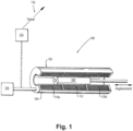
- FIG. 1 an illustrative view of an embodiment of a system in accordance with the disclosure is shown in Fig. 1 and is designated generally by reference character 100.
- FIG. 2-11 Other embodiments and/or aspects of this disclosure are shown in Figs. 2-11 .
- the one or more electronic components 106 of the variable differential transformer 102 can include a primary coil 112 wound around the moveable magnetic core 108.
- the primary coil 112 can be configured to receive current from the power source 110 (e.g., via electrical connection between the transformer 102 and the external power supply 110).
- the primary coil 112 can include a high side line 114 and a low side line 116 each operatively connected to the power source 110.
- At least one secondary coil 118 can be wound around the moveable magnetic core 108 wound in one continuous direction and magnetically coupled to the primary winding 112. For example, as shown in Fig. 2 , a single secondary coil 118 is shown.
- the controller 126 can be configured to sample a voltage of the first side line 120 with respect to the center-tap 124 and a voltage of the second side line 122 with respect to the center-tap 124 and determine a sum voltage of the first side line 120 and the second side line 122.
- the controller 126 can be configured to compare the sampled sum voltage to a known sum voltage and determine if a fault has occurred across the secondary coil 118 if the difference between the sum voltage of the first side line 120 and the second side line 122 and the known sum voltage is greater than a predetermined threshold.
- the transformer 202 can be a six-wire transformer, where the secondary coil includes a first and second secondary coil 218a, 218b. Each secondary coil can include a high side line and a low side line.
- the first secondary coil 218a can include high side line 228 and low side line 230
- the second secondary coil 218b can include high side line 232 and low side line 234.
- the secondary windings of the variable differential transformer can be connected in series-aiding polarities (e.g., instead of the conventional series-opposing polarities).
- the secondary windings can be wound in the series-aiding polarity across the center tap, and in a 6-wire system, the first and second secondary windings can be connected in the series-aiding polarity, where both secondary coils are wound in the same direction.
- variable differential transformers where the secondary coils are wound as series-opposing, produce legitimate Va, Vb, (Va+Vb) amplitudes during short between the first and second lines, and thus BIT cannot detect the short at any position of the transformer. But because of the series-aiding windings, embodiments produce small (e.g., out-of-range) amplitudes during short between the first and second lines allowing BIT to detect the short at all positions of the transformer. Therefore embodiments provide improved methods for detecting a fault in a variable differential transformer.
- any numerical values disclosed herein can be exact values or can be values within a range. Further, any terms of approximation (e.g., “about”, “approximately”, “around”) used in this disclosure can mean the stated value within a range. For example, in certain embodiments, the range can be within (plus or minus) 20%, or within 10%, or within 5%, or within 2%, or within any other suitable percentage or number as appreciated by those having ordinary skill in the art (e.g., for known tolerance limits or error ranges).
Landscapes
- Engineering & Computer Science (AREA)
- Power Engineering (AREA)
- Physics & Mathematics (AREA)
- General Physics & Mathematics (AREA)
- Testing Of Short-Circuits, Discontinuities, Leakage, Or Incorrect Line Connections (AREA)
Abstract
Description
- The present disclosure relates to variable differential transformers, and more particularly to fault detection in variable differential transformers.
- Measurement devices, such as variable differential transformers, can be used as absolute position sensors. In certain applications, for example, in aircraft, linear variable differential transformers and rotary variable differential transformers need to provide precise position measurements. But due to their inclusion in harsh environments, they may experience faults or shorts leading to inaccurate measurements, or failure altogether. In such cases, it is critical to know of a fault so that any measurements from the faulty device can be disregarded. Typical interfaces include some form of short circuit detection, however detecting a short across secondary coils of the devices has been difficult.
- There remains a need in the art for improvements to short detection in variable differential transformers, for example in the aerospace industry, which allows for enhanced short detection within the secondary coils. This disclosure provides a solution for this need.
- In accordance with at least one aspect of this disclosure, a system includes a primary coil wound around a moveable magnetic core configured to receive current from a power source. At least one secondary coil is wound around the moveable magnetic core in one continuous direction and magnetically coupled with the primary coil. The secondary coil can be wound around the moveable magnetic core such that the winding direction for the entire secondary coil is in the same direction. A controller is operatively connected to determine a position of the moveable magnetic core and configured to detect a fault across the secondary coil. In embodiments, the at least one secondary coil can be wound in a series-aiding configuration. In certain embodiments, the at least one secondary coil can include a single, continuous secondary coil, and the single, continuous secondary coil can be wound in a series-aiding configuration relative to the secondary coil center-tap.
- In embodiments, the system can include the power source and the primary coil can include a high side line and a low side line each operatively connected to the power source. In certain embodiments, the secondary coil can include a first side line, a second side line, and one center-tap. In embodiments, the secondary coil can be wound such that the first side line and the second side line of the secondary coil are 180 degrees out of phase relative to one another.
- In embodiments, the controller can be configured to perform a built-in-test (BIT) function to determine if a fault has occurred across the secondary coil. The controller can be configured to (e.g., in performing the BIT function) sample a voltage of the first side line with respect to the center-tap and a voltage of the second side line with respect to the center-tap and determine a sum voltage of the first side line and the second side line. The controller can be configured to compare the sampled sum voltage to a known sum voltage and determine if a fault has occurred across the secondary coil if the difference between the sum voltage of the first side line with respect to the center-tap and the second side line with respect to the center-tap and the known sum voltage is greater than a predetermined threshold. The controller can be configured to determine if a fault has occurred across the secondary coil if the sum voltage of the first side line with respect to the center-tap and the second side line with respect to the center-tap is at or near zero.
- In embodiments, the primary coil, the at least one secondary coil, and the moveable magnetic core can form a variable differential transformer. In certain embodiments, the variable differential transformer can include a linear variable differential transformer. In certain embodiments, the variable differential transformer can include a rotary variable differential transformer.
- In certain embodiments, the variable differential transformer can include a five-wire variable differential transformer. In certain such embodiments, the at least one secondary coil can be a single center-tapped secondary coil. The single secondary coil can be one continuous winding wound around the moveable magnetic core in one direction.
- In certain embodiments, the variable differential transformer can include a six-wire variable differential transformer. In certain such embodiments, the at least one secondary coil can include two secondary coils. A first secondary coil can be wound around the moveable magnetic core in a first winding direction and a second secondary coil can be wound around the moveable magnetic core in a second winding direction. In embodiments, the first winding direction can be the same as the second winding direction such that the first and second secondary windings are in a series-aiding configuration.
- In accordance with at least one aspect of this disclosure, a method can include detecting a fault in at least one secondary winding of a variable differential transformer across a first side line with respect to a center-tap and a second side line with respect to the center-tap using a sum voltage of the first side line and the second side line, and outputting a fault detection signal to a user indicting the fault. In embodiments, the secondary winding can be wound in one continuous direction. In certain embodiments, the at least one secondary winding can include one secondary winding wound in one direction. In certain embodiments, the at least one secondary winding can include two secondary windings wound in the same direction relative to one another.
- In embodiments, detecting can include sampling a voltage of the first line of the at least one secondary winding with respect to the center-tap, sampling a voltage of the second side line of the at least one secondary winding with respect to a center-tap and summing the voltage of the first side line and the second side line.
- In embodiments, detecting can include comparing the sum voltage to a known sum voltage and detecting a fault if the difference between the sum voltage of the first side line and the second side line is the known sum voltage is greater than a predetermined threshold. In embodiments, detecting can include detecting a fault if the sum voltage is at or near 0.
- These and other features of the embodiments of the subject disclosure will become more readily apparent to those skilled in the art from the following detailed description taken in conjunction with the drawings.
- So that those skilled in the art to which the subject disclosure appertains will readily understand how to make and use the devices and methods of the subject disclosure without undue experimentation, embodiments thereof will be described in detail herein below with reference to certain figures, wherein:
-
Fig. 1 is a dissected perspective view of an embodiment of a variable differential transformer in accordance with this disclosure, showing a core of the variable differential transformer moving between a retracted position and an extended position; -
Fig. 2 is a schematic diagram of one or more electronic components within the variable differential transformer ofFig. 1 ; -
Fig. 3a is a schematic diagram of one or more electronic components within the variable differential transformer ofFig. 1 ; -
Fig. 3b is a graph showing a voltage phase relationship with respect to ground of the one or more electrical components in an operational state; -
Fig. 4a is a schematic view of one or more electronic components within the variable differential transformer ofFig. 1 showing a fault condition; -
Fig. 4b is a graph showing a phase relationship of the one or more electrical components in a faulted state; -
Fig. 5 is a numeric graphical representation of simulated DC equivalent sampled voltages with respect to a center-tap for the one or more electrical components during the operational state and the faulted state; -
Fig. 6 is a graphical representation of the waveforms for the simulated AC sinusoidal sampled voltages with respect to a center-tap in a compressed time scale for the one or more electrical components at a given position during the operational state and the faulted state; -
Fig. 7 is a time-expanded graphical representation of the AC sinusoidal waveforms with respect to a center-tap ofFig. 6 ; -
Fig. 8 is a schematic view of one or more electronic components within another embodiment of a variable differential transformer; -
Fig. 9a is a schematic view of one or more electronic components within the variable differential transformer ofFig. 8 ; -
Fig. 9b is a graph showing a voltage phase relationship with respect to ground of the one or more electrical components in an operational state; -
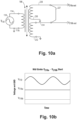
Fig. 10a is a schematic view of one or more electronic components within the variable differential transformer ofFig. 8 ; -
Fig. 10b is a graph showing a phase relationship of the one or more electrical components with respect to a center tap in a faulted state; -
Fig. 11 is a box diagram of a method in accordance with at least one aspect of this disclosure. - Reference will now be made to the drawings wherein like reference numerals identify similar structural features or aspects of the subject disclosure. For purposes of explanation and illustration, and not limitation, an illustrative view of an embodiment of a system in accordance with the disclosure is shown in
Fig. 1 and is designated generally byreference character 100. Other embodiments and/or aspects of this disclosure are shown inFigs. 2-11 . - In accordance with at least one aspect of this disclosure, a
system 100 can include a variabledifferential transformer 102 defined by ahousing 104, including one or more electronic components 106, and a moveablemagnetic core 108. The one or more electronic components 106 can include any suitable hardware and/or software configured to receive power from apower supply 110 and determine a position of the moveablemagnetic core 108. The variabledifferential transformer 102 can include a linear variable differential transformer, e.g., as shown, or in certain embodiments, the variable differential transformer can include a rotary variable differential transformer, for example. - As shown in
Figs. 1-3 , the one or more electronic components 106 of the variabledifferential transformer 102 can include aprimary coil 112 wound around the moveablemagnetic core 108. Theprimary coil 112 can be configured to receive current from the power source 110 (e.g., via electrical connection between thetransformer 102 and the external power supply 110). Theprimary coil 112 can include ahigh side line 114 and alow side line 116 each operatively connected to thepower source 110. At least onesecondary coil 118 can be wound around the moveablemagnetic core 108 wound in one continuous direction and magnetically coupled to the primary winding 112. For example, as shown inFig. 2 , a singlesecondary coil 118 is shown. Thesecondary coil 118 can include afirst side line 120, asecond side line 122, and at least one center-tap 124. In certain embodiments, thesecondary coil 118 can be wound in a single continuous direction (e.g., along an entire length of the core 108) such that thefirst side line 120 and thesecond side line 122 of the secondary coil are 180 degrees out of phase relative to one another. - The one or more electronic components 106 of the variable
differential transformer 102 can include acontroller 126, or acontroller 126 can be operatively connected to the variabledifferential transformer 102, to determine the position of the moveablemagnetic core 108. Thecontroller 126 can also be configured to detect a fault across thesecondary coil 118. For example, thecontroller 126 can be configured to perform a built-in-test (BIT) function to determine if a fault has occurred across thesecondary coil 118. - As shown in
Figs. 4a-4b , to conduct the BIT function, thecontroller 126 can be configured to sample a voltage of thefirst side line 120 with respect to the center-tap 124 and a voltage of thesecond side line 122 with respect to the center-tap 124 and determine a sum voltage of thefirst side line 120 and thesecond side line 122. Thecontroller 126 can be configured to compare the sampled sum voltage to a known sum voltage and determine if a fault has occurred across thesecondary coil 118 if the difference between the sum voltage of thefirst side line 120 and thesecond side line 122 and the known sum voltage is greater than a predetermined threshold. In certain embodiments, thecontroller 126 can be configured to compare the sampled sum voltage to a known predetermined threshold and determine if a fault has occurred across thesecondary coil 118 if the sampled sum voltage is less than the predetermined threshold. One having ordinary skill in the art in view of this disclosure would understand what an appropriate predetermined threshold would be in the given context without undue experimentation. - Providing a predetermined threshold allows for some tolerance in the voltage samplings and imperfections in a practical variable
differential transformer 102. But if the difference between the sampled sum voltage and the known voltage exceeds the threshold, thecontroller 126 will determine that a fault has occurred in thetransformer 102, the fault including ashort circuit 127 from thefirst side line 120 to thesecond side line 122. This can be seen schematically inFig. 4 , for example. In certain conditions, afault 127 across thesecondary coil 118 will be detected if the sum voltage of thefirst side line 120 with respect to the center-tap and thesecond side line 122 with respect to the center-tap is less than a predetermined threshold, or when the sum voltage is at or near zero. - Conventionally (e.g., when the secondary coil on either side of the center-tap is wound in a series-opposing configuration), it may be difficult to observe a difference in sampled sum voltage to known sum voltage because the difference between the sampled and known sums will be slight. But winding the
secondary coil 118 on either side of the center-tap in a series-aiding configuration as described herein will collapse the voltages across the secondary coil during a fault so that the voltage at both the first side line and the second side line will be at or near zero, resulting in a sampled sum voltage of near zero or zero, such as shown inFigs. 5-7 . This will make the fault much easier for the controller to detect. - In accordance with at least one aspect of this disclosure, another embodiment of a system 200 is shown in
Figs. 8-10 . The system 200 can have similar components and features with respect tosystem 100. For brevity, the description of common elements that have been described above forsystem 100 are not repeated with respect to the system 200 as shown inFigs. 8-10 . In system 200, thetransformer 202 can be a six-wire transformer, where the secondary coil includes a first and secondsecondary coil secondary coil 218a can includehigh side line 228 andlow side line 230, and the secondsecondary coil 218b can includehigh side line 232 andlow side line 234. The first and secondsecondary coils system 100, such that bothsecondary coils controller 126 can be configured to perform the same BIT function on the system 200 as performed insystem 100, in a similar manner, e.g., to detect the fault orshort circuit 227 across thesecondary coils Figs. 10a-10b . - In accordance with at least one aspect of this disclosure, as shown in
Fig. 11 , a method (e.g., a built-in-test method) can include, detecting a fault in a secondary winding (e.g., winding 118, 218a, 218b) of a variable differential transformer (e.g.,transformer 102, 202) across a first side line (e.g.,lines lines - In embodiments, detecting can include sampling a voltage of the first line of the secondary winding with respect to a center-tap, sampling a voltage of the second side line of the secondary winding with respect to the center-tap, and summing the voltage of the first side line and the second side line.
- In embodiments, detecting can include comparing the sum voltage to a known sum voltage and detecting a fault if the difference between the sum voltage of the first side line and the second side line is the known sum voltage is greater than a predetermined threshold. In embodiments, detecting can include detecting a fault if the sum voltage is at or near 0.
- Variable differential transformers can be used in a wide range of applications to determine a position of a given object. For example, in aerospace applications, the variable
differential transformer 102 can be used to determine a position of an aircraft control surface, or a position of a valve in a fuel system, among other things. It is important for proper function of aircraft systems that such position measurements are accurate. Therefore, detecting faults within the variable differential transformers (and/or wiring faults can between the variable differential transformer and controller) is critical for ensuring the measurements being relied upon are in fact reflective of the current state of the system. Embodiments provide a more effective means to detect a short circuit between the first and second lines of a 5-wire and 6-wire variable differential transformers (e.g., linear or rotary). The secondary windings of the variable differential transformer can be connected in series-aiding polarities (e.g., instead of the conventional series-opposing polarities). In a 5-wire system, the secondary windings can be wound in the series-aiding polarity across the center tap, and in a 6-wire system, the first and second secondary windings can be connected in the series-aiding polarity, where both secondary coils are wound in the same direction. - Embodiments may employ ratiometric processing, where transformer position is a function of [(Va-Vb)/(Va+Vb)] as well as built in test (BIT) methods using such functions, including a "sum voltage check" (Va+Vb), or checks on the magnitudes of Va or Vb, or checks on the frequency of Va or Vb. In embodiments, the first line of the secondary winding (Va) with respect to a center-tap (VCOM) and the second line of the secondary winding (Vb) with respect to the center-tap can be 180 degrees out-of-phase. In the transformer wound in a series-aiding winding, when a short circuit occurs across the first and second lines, the shorted first and second lines tend to produce zero volts with respect to the center-tap (e.g., ground).
- Conventional variable differential transformers where the secondary coils are wound as series-opposing, produce legitimate Va, Vb, (Va+Vb) amplitudes during short between the first and second lines, and thus BIT cannot detect the short at any position of the transformer. But because of the series-aiding windings, embodiments produce small (e.g., out-of-range) amplitudes during short between the first and second lines allowing BIT to detect the short at all positions of the transformer. Therefore embodiments provide improved methods for detecting a fault in a variable differential transformer.
- As will be appreciated by those skilled in the art, aspects of the present disclosure may be embodied as a system, method or computer program product. Accordingly, aspects of this disclosure (e.g., electronic components 106 and/or controller 126) may take the form of an entirely hardware embodiment, an entirely software embodiment (including firmware, resident software, micro-code, etc.), or an embodiment combining software and hardware aspects, all possibilities of which can be referred to herein as a "circuit," "module," or "system." A "circuit," "module," or "system" can include one or more portions of one or more separate physical hardware and/or software components that can together perform the disclosed function of the "circuit," "module," or "system", or a "circuit," "module," or "system" can be a single self-contained unit (e.g., of hardware and/or software). Furthermore, aspects of this disclosure may take the form of a computer program product embodied in one or more computer readable medium(s) having computer readable program code embodied thereon.
- Computer program instructions may also be stored in a computer readable medium that can direct a computer, other programmable data processing apparatus, or other devices to function in a particular manner. The computer program instructions may also be loaded onto a computer, other programmable data processing apparatus, or other devices to cause a series of operational steps to be performed on the computer, other programmable apparatus or other devices to produce a computer implemented process such that the instructions which execute on the computer or other programmable apparatus provide processes for implementing the functions/acts specified herein.
- Those having ordinary skill in the art understand that any numerical values disclosed herein can be exact values or can be values within a range. Further, any terms of approximation (e.g., "about", "approximately", "around") used in this disclosure can mean the stated value within a range. For example, in certain embodiments, the range can be within (plus or minus) 20%, or within 10%, or within 5%, or within 2%, or within any other suitable percentage or number as appreciated by those having ordinary skill in the art (e.g., for known tolerance limits or error ranges).
- The articles "a", "an", and "the" as used herein and in the appended claims are used herein to refer to one or to more than one (i.e., to at least one) of the grammatical object of the article unless the context clearly indicates otherwise. By way of example, "an element" means one element or more than one element.
- The phrase "and/or," as used herein in the specification and in the claims, should be understood to mean "either or both" of the elements so conjoined, i.e., elements that are conjunctively present in some cases and disjunctively present in other cases. Multiple elements listed with "and/or" should be construed in the same fashion, i.e., "one or more" of the elements so conjoined. Other elements may optionally be present other than the elements specifically identified by the "and/or" clause, whether related or unrelated to those elements specifically identified. Thus, as a non-limiting example, a reference to "A and/or B", when used in conjunction with open-ended language such as "comprising" can refer, in one embodiment, to A only (optionally including elements other than B); in another embodiment, to B only (optionally including elements other than A); in yet another embodiment, to both A and B (optionally including other elements); etc.
- As used herein in the specification and in the claims, "or" should be understood to have the same meaning as "and/or" as defined above. For example, when separating items in a list, "or" or "and/or" shall be interpreted as being inclusive, i.e., the inclusion of at least one, but also including more than one, of a number or list of elements, and, optionally, additional unlisted items. Only terms clearly indicated to the contrary, such as "only one of' or "exactly one of," or, when used in the claims, "consisting of," will refer to the inclusion of exactly one element of a number or list of elements. In general, the term "or" as used herein shall only be interpreted as indicating exclusive alternatives (i.e., "one or the other but not both") when preceded by terms of exclusivity, such as "either," "one of," "only one of," or "exactly one of."
- Any suitable combination(s) of any disclosed embodiments and/or any suitable portion(s) thereof are contemplated herein as appreciated by those having ordinary skill in the art in view of this disclosure.
- The embodiments of the present disclosure, as described above and shown in the drawings, provide for improvement in the art to which they pertain. While the apparatus and methods of the subject disclosure have been shown and described, those skilled in the art will readily appreciate that changes and/or modifications may be made thereto without departing from the scope of the subject disclosure.
Claims (15)
- A system, comprising:a primary coil (112) wound around a moveable magnetic core (108);at least one secondary coil (118, 218a, 218b) wound around the moveable magnetic core (108) in one continuous direction and magnetically coupled with the primary coil (112); anda controller (126) operatively connected to determine a position of the moveable magnetic core (108) and configured to detect a fault across the secondary coil (118, 218a, 218b).
- The system of claim 1, wherein the secondary coil (118, 218a, 218b) includes a first side line, a second side line, and a center-tap.
- The system of claim 2, wherein the first side line and the second side line of the at least one secondary coil (118, 218a, 218b) are 180 degrees out of phase relative to one another.
- The system of any preceding claim, wherein the controller (126) is configured to perform a built-in-test (BIT) function to determine if a fault has occurred across the secondary coil (118, 218a, 218b).
- The system of any preceding claim, wherein the controller (126) is configured to sample a voltage of the first side line with respect to the center-tap and a voltage of the second side line with respect to the center-tap and determine a sum voltage of the first side line and the second side line.
- The system of any preceding claim, wherein the controller (126) is configured to compare the sampled sum voltage to a known sum voltage and determine if a fault has occurred across the secondary coil (118, 218a, 218b) if a difference between the sum voltage of the first side line with respect to the center-tap and the second side line with respect to the center-tap and the known sum voltage is greater than a predetermined threshold.
- The system of any preceding claim, wherein the controller (126) is configured to determine if a fault has occurred across the secondary coil (118, 218a, 218b) if the sum voltage of the first side line with respect to the center-tap and the second side line with respect to the center-tap is at or near zero.
- The system of any preceding claim, wherein the primary coil (112), the at least one secondary coil (118, 218a, 218b), and the moveable magnetic core (108) form a variable differential transformer, and optionally wherein the variable differential transformer includes a linear variable differential transformer, or wherein the variable differential transformer includes a rotary variable differential transformer.
- The system of any preceding claim, wherein the variable differential transformer includes a five-wire variable differential transformer such that the at least one secondary coil (118, 218a, 218b) includes a single center-tapped secondary coil (118, 218a, 218b), wherein the single secondary coil (118, 218a, 218b) is one continuous winding wound around the moveable magnetic core (108) in one direction.
- The system of any preceding claim, wherein the variable differential transformer includes a six-wire variable differential transformer such that the at least one secondary coil (118, 218a, 218b) includes two secondary coils.
- The system of claim 10, wherein a first secondary coil (118, 218a, 218b) is wound around the moveable magnetic core (108) in a first winding direction and a second secondary coil (118, 218a, 218b) is wound around the moveable magnetic core (108) in a second winding direction, and optionally wherein the first winding direction is the same as the second winding direction.
- A method, comprising:detecting a fault in at least one secondary winding of a variable differential transformer across a first side line with respect to a center-tap and a second side line with respect to the center-tap using a sum voltage of the first side line and the second side line; andoutputting a fault detection signal to a user indicting the fault.
- The method of claim 12, wherein the at least one secondary winding includes one secondary winding wound in one direction, or .wherein the at least one secondary winding includes two secondary windings wound in the same direction relative to one another.
- The method of any of claims12 to 13, wherein detecting includes:sampling a voltage of the first line of the at least one secondary winding with respect to the center-tap;sampling a voltage of the second side line of the at least one secondary winding with respect to the center-tap; andsumming the voltage of the first side line and the second side line.
- The method of claim 14, wherein detecting includes:comparing the sum voltage to a known sum voltage; anddetecting a fault if a difference between the sum voltage of the first side line and the second side line is greater than a predetermined threshold, orwherein detecting includes:comparing the sum voltage to a known sum voltage; anddetecting a fault if a difference between the sum voltage of the first side line and the second side line is at or near zero.
Applications Claiming Priority (1)
| Application Number | Priority Date | Filing Date | Title |
|---|---|---|---|
| US17/848,916 US11959977B2 (en) | 2022-06-24 | 2022-06-24 | Systems and methods for fault detection in variable differential transformers |
Publications (1)
| Publication Number | Publication Date |
|---|---|
| EP4296622A1 true EP4296622A1 (en) | 2023-12-27 |
Family
ID=87047899
Family Applications (1)
| Application Number | Title | Priority Date | Filing Date |
|---|---|---|---|
| EP23181149.8A Pending EP4296622A1 (en) | 2022-06-24 | 2023-06-23 | Systems and methods for fault detection in variable differential transformers |
Country Status (2)
| Country | Link |
|---|---|
| US (1) | US11959977B2 (en) |
| EP (1) | EP4296622A1 (en) |
Citations (5)
| Publication number | Priority date | Publication date | Assignee | Title |
|---|---|---|---|---|
| US5767670A (en) * | 1996-08-29 | 1998-06-16 | Texas Instruments Incorporated | Method and apparatus for providing improved temperature compensated output for variable differential transformer system |
| US20150142353A1 (en) * | 2012-06-25 | 2015-05-21 | Snecma | Monitoring a linear variable differential transformer sensor |
| CN105527530A (en) * | 2014-09-28 | 2016-04-27 | 中国航空工业集团公司西安飞机设计研究所 | Displacement sensor wire disconnection detection circuit, detection method and signal reconstruction method thereof |
| US20170016946A1 (en) * | 2015-07-16 | 2017-01-19 | The Boeing Company | Linear Variable Differential Transformer (LVDT) Secondary Wiring Intermittent Failure Monitor |
| US20220003809A1 (en) * | 2020-07-02 | 2022-01-06 | Baker Hughes Oilfield Operations Llc | Sensor circuit diagnosis |
Family Cites Families (14)
| Publication number | Priority date | Publication date | Assignee | Title |
|---|---|---|---|---|
| US4416057A (en) * | 1981-05-28 | 1983-11-22 | Western Electric Company, Inc. | Methods of testing the integrity of an electrical coil as it is wound |
| US5210490A (en) * | 1989-01-11 | 1993-05-11 | Nartron Corporation | Linear position sensor having coaxial or parallel primary and secondary windings |
| US7138794B1 (en) | 2000-03-10 | 2006-11-21 | General Electric Company | Detection of faults in linear and rotary voltage transducers |
| US7317371B1 (en) * | 2007-02-21 | 2008-01-08 | Pearl Process Systems, Llc | Linear variable differential transformer with complimentary step-winding secondary coils |
| US8712710B2 (en) * | 2011-05-13 | 2014-04-29 | Honeywell International Inc. | Method and apparatus for detection of LVDT core fallout condition |
| GB2492168A (en) | 2011-06-24 | 2012-12-26 | Penny & Giles Controls Ltd | Inductive position sensor with datum adjustment |
| US9448275B2 (en) * | 2013-06-25 | 2016-09-20 | The Boeing Company | Fault detection of four wire variable differential transformer sensors |
| US9952064B2 (en) * | 2013-11-26 | 2018-04-24 | Honeywell International Inc. | Transformer position sensor with shorted coil |
| US9638735B2 (en) * | 2015-07-15 | 2017-05-02 | The Boeing Company | Linear variable differential transformer (LVDT) excitation wiring intermittent failure monitor |
| US10345357B2 (en) * | 2016-02-29 | 2019-07-09 | The Boeing Company | Fault detection in variable differential transformer sensors based on zero-crossings of signals |
| US10446310B2 (en) * | 2016-06-01 | 2019-10-15 | Honeywell International Inc. | Linear variable displacement transformer (LVDT) with improved linearity using extreme end booster winding |
| US10332675B2 (en) * | 2017-01-09 | 2019-06-25 | Honeywell International Inc. | Linear variable displacement transformer (LVDT) with improved sensitivity and linearity using fractional winding technique |
| US11209290B2 (en) | 2018-07-09 | 2021-12-28 | Hamilton Sundstrand Corporation | Resolver/LVDT odd harmonic distortion compensation |
| US11557430B2 (en) * | 2020-02-19 | 2023-01-17 | Eaton Intelligent Power Limited | Current transformer powered controller |
-
2022
- 2022-06-24 US US17/848,916 patent/US11959977B2/en active Active
-
2023
- 2023-06-23 EP EP23181149.8A patent/EP4296622A1/en active Pending
Patent Citations (5)
| Publication number | Priority date | Publication date | Assignee | Title |
|---|---|---|---|---|
| US5767670A (en) * | 1996-08-29 | 1998-06-16 | Texas Instruments Incorporated | Method and apparatus for providing improved temperature compensated output for variable differential transformer system |
| US20150142353A1 (en) * | 2012-06-25 | 2015-05-21 | Snecma | Monitoring a linear variable differential transformer sensor |
| CN105527530A (en) * | 2014-09-28 | 2016-04-27 | 中国航空工业集团公司西安飞机设计研究所 | Displacement sensor wire disconnection detection circuit, detection method and signal reconstruction method thereof |
| US20170016946A1 (en) * | 2015-07-16 | 2017-01-19 | The Boeing Company | Linear Variable Differential Transformer (LVDT) Secondary Wiring Intermittent Failure Monitor |
| US20220003809A1 (en) * | 2020-07-02 | 2022-01-06 | Baker Hughes Oilfield Operations Llc | Sensor circuit diagnosis |
Also Published As
| Publication number | Publication date |
|---|---|
| US20230417845A1 (en) | 2023-12-28 |
| US11959977B2 (en) | 2024-04-16 |
Similar Documents
| Publication | Publication Date | Title |
|---|---|---|
| EP2818834A1 (en) | Fault detection of four wire variable differential transformer sensors | |
| US20130193959A1 (en) | Detection of a Metal or Magnetic Object | |
| US10401395B2 (en) | Monitoring a linear variable differential transformer sensor | |
| CN108693464B (en) | Analog input circuit sensing for fault detection | |
| CN104380124B (en) | The apparatus and method for that fault detect and position are determined | |
| US7138794B1 (en) | Detection of faults in linear and rotary voltage transducers | |
| EP3505872B1 (en) | Method and system for detecting resolver/synchro faults | |
| WO2018221619A1 (en) | Electricity leakage detecting method | |
| EP2707731A2 (en) | Method and apparatus for detection of lvdt core fallout condition | |
| US11959977B2 (en) | Systems and methods for fault detection in variable differential transformers | |
| US9696184B2 (en) | Position-detecting unit having reduced offset voltage, and method using such a unit | |
| US10345357B2 (en) | Fault detection in variable differential transformer sensors based on zero-crossings of signals | |
| Freiburg et al. | Capacitive voltage transformers-electrical performance and effective diagnostic measures | |
| US7358720B1 (en) | Proximity sensor interface | |
| US11441928B2 (en) | Method for testing a sensor | |
| WO2023277178A1 (en) | Impedance measurement system | |
| CN100365419C (en) | Non-contact measuring system for direct current | |
| EP3933346B1 (en) | Sensor circuit diagnosis | |
| EP4080703B1 (en) | Partial rms based over-current detection for vdt excitation | |
| US11994414B2 (en) | Transformer with test circuit | |
| US11822035B2 (en) | Passive inductive proximity sensor array signal processing circuit | |
| CN106093581A (en) | The eddy current measuring method of conductive film square resistance | |
| Radovanović et al. | Signal acquisition and processing in the magnetic defectoscopy of steel wire ropes | |
| Kuliński et al. | Frequency response testing of zero-sequence current transformers for mining ground fault protection relays | |
| JP5429575B2 (en) | Resolver signal processing device |
Legal Events
| Date | Code | Title | Description |
|---|---|---|---|
| PUAI | Public reference made under article 153(3) epc to a published international application that has entered the european phase |
Free format text: ORIGINAL CODE: 0009012 |
|
| STAA | Information on the status of an ep patent application or granted ep patent |
Free format text: STATUS: THE APPLICATION HAS BEEN PUBLISHED |
|
| AK | Designated contracting states |
Kind code of ref document: A1 Designated state(s): AL AT BE BG CH CY CZ DE DK EE ES FI FR GB GR HR HU IE IS IT LI LT LU LV MC ME MK MT NL NO PL PT RO RS SE SI SK SM TR |
|
| STAA | Information on the status of an ep patent application or granted ep patent |
Free format text: STATUS: REQUEST FOR EXAMINATION WAS MADE |
|
| 17P | Request for examination filed |
Effective date: 20240626 |
|
| RBV | Designated contracting states (corrected) |
Designated state(s): AL AT BE BG CH CY CZ DE DK EE ES FI FR GB GR HR HU IE IS IT LI LT LU LV MC ME MK MT NL NO PL PT RO RS SE SI SK SM TR |
|
| STAA | Information on the status of an ep patent application or granted ep patent |
Free format text: STATUS: EXAMINATION IS IN PROGRESS |
|
| 17Q | First examination report despatched |
Effective date: 20251112 |