EP4296593A1 - Air-conditioning device - Google Patents
Air-conditioning device Download PDFInfo
- Publication number
- EP4296593A1 EP4296593A1 EP21926490.0A EP21926490A EP4296593A1 EP 4296593 A1 EP4296593 A1 EP 4296593A1 EP 21926490 A EP21926490 A EP 21926490A EP 4296593 A1 EP4296593 A1 EP 4296593A1
- Authority
- EP
- European Patent Office
- Prior art keywords
- opening degree
- map
- value
- expansion valve
- controller
- Prior art date
- Legal status (The legal status is an assumption and is not a legal conclusion. Google has not performed a legal analysis and makes no representation as to the accuracy of the status listed.)
- Withdrawn
Links
Images




Classifications
-
- F—MECHANICAL ENGINEERING; LIGHTING; HEATING; WEAPONS; BLASTING
- F24—HEATING; RANGES; VENTILATING
- F24F—AIR-CONDITIONING; AIR-HUMIDIFICATION; VENTILATION; USE OF AIR CURRENTS FOR SCREENING
- F24F11/00—Control or safety arrangements
- F24F11/70—Control systems characterised by their outputs; Constructional details thereof
- F24F11/80—Control systems characterised by their outputs; Constructional details thereof for controlling the temperature of the supplied air
- F24F11/83—Control systems characterised by their outputs; Constructional details thereof for controlling the temperature of the supplied air by controlling the supply of heat-exchange fluids to heat-exchangers
- F24F11/84—Control systems characterised by their outputs; Constructional details thereof for controlling the temperature of the supplied air by controlling the supply of heat-exchange fluids to heat-exchangers using valves
-
- F—MECHANICAL ENGINEERING; LIGHTING; HEATING; WEAPONS; BLASTING
- F25—REFRIGERATION OR COOLING; COMBINED HEATING AND REFRIGERATION SYSTEMS; HEAT PUMP SYSTEMS; MANUFACTURE OR STORAGE OF ICE; LIQUEFACTION SOLIDIFICATION OF GASES
- F25B—REFRIGERATION MACHINES, PLANTS OR SYSTEMS; COMBINED HEATING AND REFRIGERATION SYSTEMS; HEAT PUMP SYSTEMS
- F25B13/00—Compression machines, plants or systems, with reversible cycle
-
- F—MECHANICAL ENGINEERING; LIGHTING; HEATING; WEAPONS; BLASTING
- F24—HEATING; RANGES; VENTILATING
- F24F—AIR-CONDITIONING; AIR-HUMIDIFICATION; VENTILATION; USE OF AIR CURRENTS FOR SCREENING
- F24F11/00—Control or safety arrangements
- F24F11/62—Control or safety arrangements characterised by the type of control or by internal processing, e.g. using fuzzy logic, adaptive control or estimation of values
- F24F11/63—Electronic processing
-
- F—MECHANICAL ENGINEERING; LIGHTING; HEATING; WEAPONS; BLASTING
- F25—REFRIGERATION OR COOLING; COMBINED HEATING AND REFRIGERATION SYSTEMS; HEAT PUMP SYSTEMS; MANUFACTURE OR STORAGE OF ICE; LIQUEFACTION SOLIDIFICATION OF GASES
- F25B—REFRIGERATION MACHINES, PLANTS OR SYSTEMS; COMBINED HEATING AND REFRIGERATION SYSTEMS; HEAT PUMP SYSTEMS
- F25B41/00—Fluid-circulation arrangements
- F25B41/30—Expansion means; Dispositions thereof
- F25B41/31—Expansion valves
- F25B41/34—Expansion valves with the valve member being actuated by electric means, e.g. by piezoelectric actuators
- F25B41/345—Expansion valves with the valve member being actuated by electric means, e.g. by piezoelectric actuators by solenoids
- F25B41/347—Expansion valves with the valve member being actuated by electric means, e.g. by piezoelectric actuators by solenoids with the valve member being opened and closed cyclically, e.g. with pulse width modulation
-
- F—MECHANICAL ENGINEERING; LIGHTING; HEATING; WEAPONS; BLASTING
- F25—REFRIGERATION OR COOLING; COMBINED HEATING AND REFRIGERATION SYSTEMS; HEAT PUMP SYSTEMS; MANUFACTURE OR STORAGE OF ICE; LIQUEFACTION SOLIDIFICATION OF GASES
- F25B—REFRIGERATION MACHINES, PLANTS OR SYSTEMS; COMBINED HEATING AND REFRIGERATION SYSTEMS; HEAT PUMP SYSTEMS
- F25B49/00—Arrangement or mounting of control or safety devices
- F25B49/02—Arrangement or mounting of control or safety devices for compression type machines, plants or systems
-
- F—MECHANICAL ENGINEERING; LIGHTING; HEATING; WEAPONS; BLASTING
- F24—HEATING; RANGES; VENTILATING
- F24F—AIR-CONDITIONING; AIR-HUMIDIFICATION; VENTILATION; USE OF AIR CURRENTS FOR SCREENING
- F24F2140/00—Control inputs relating to system states
- F24F2140/20—Heat-exchange fluid temperature
-
- F—MECHANICAL ENGINEERING; LIGHTING; HEATING; WEAPONS; BLASTING
- F25—REFRIGERATION OR COOLING; COMBINED HEATING AND REFRIGERATION SYSTEMS; HEAT PUMP SYSTEMS; MANUFACTURE OR STORAGE OF ICE; LIQUEFACTION SOLIDIFICATION OF GASES
- F25B—REFRIGERATION MACHINES, PLANTS OR SYSTEMS; COMBINED HEATING AND REFRIGERATION SYSTEMS; HEAT PUMP SYSTEMS
- F25B2600/00—Control issues
- F25B2600/25—Control of valves
- F25B2600/2513—Expansion valves
-
- F—MECHANICAL ENGINEERING; LIGHTING; HEATING; WEAPONS; BLASTING
- F25—REFRIGERATION OR COOLING; COMBINED HEATING AND REFRIGERATION SYSTEMS; HEAT PUMP SYSTEMS; MANUFACTURE OR STORAGE OF ICE; LIQUEFACTION SOLIDIFICATION OF GASES
- F25B—REFRIGERATION MACHINES, PLANTS OR SYSTEMS; COMBINED HEATING AND REFRIGERATION SYSTEMS; HEAT PUMP SYSTEMS
- F25B2700/00—Sensing or detecting of parameters; Sensors therefor
- F25B2700/21—Temperatures
- F25B2700/2104—Temperatures of an indoor room or compartment
-
- F—MECHANICAL ENGINEERING; LIGHTING; HEATING; WEAPONS; BLASTING
- F25—REFRIGERATION OR COOLING; COMBINED HEATING AND REFRIGERATION SYSTEMS; HEAT PUMP SYSTEMS; MANUFACTURE OR STORAGE OF ICE; LIQUEFACTION SOLIDIFICATION OF GASES
- F25B—REFRIGERATION MACHINES, PLANTS OR SYSTEMS; COMBINED HEATING AND REFRIGERATION SYSTEMS; HEAT PUMP SYSTEMS
- F25B2700/00—Sensing or detecting of parameters; Sensors therefor
- F25B2700/21—Temperatures
- F25B2700/2106—Temperatures of fresh outdoor air
-
- F—MECHANICAL ENGINEERING; LIGHTING; HEATING; WEAPONS; BLASTING
- F25—REFRIGERATION OR COOLING; COMBINED HEATING AND REFRIGERATION SYSTEMS; HEAT PUMP SYSTEMS; MANUFACTURE OR STORAGE OF ICE; LIQUEFACTION SOLIDIFICATION OF GASES
- F25B—REFRIGERATION MACHINES, PLANTS OR SYSTEMS; COMBINED HEATING AND REFRIGERATION SYSTEMS; HEAT PUMP SYSTEMS
- F25B2700/00—Sensing or detecting of parameters; Sensors therefor
- F25B2700/21—Temperatures
- F25B2700/2115—Temperatures of a compressor or the drive means therefor
- F25B2700/21152—Temperatures of a compressor or the drive means therefor at the discharge side of the compressor
-
- F—MECHANICAL ENGINEERING; LIGHTING; HEATING; WEAPONS; BLASTING
- F25—REFRIGERATION OR COOLING; COMBINED HEATING AND REFRIGERATION SYSTEMS; HEAT PUMP SYSTEMS; MANUFACTURE OR STORAGE OF ICE; LIQUEFACTION SOLIDIFICATION OF GASES
- F25B—REFRIGERATION MACHINES, PLANTS OR SYSTEMS; COMBINED HEATING AND REFRIGERATION SYSTEMS; HEAT PUMP SYSTEMS
- F25B2700/00—Sensing or detecting of parameters; Sensors therefor
- F25B2700/21—Temperatures
- F25B2700/2116—Temperatures of a condenser
-
- F—MECHANICAL ENGINEERING; LIGHTING; HEATING; WEAPONS; BLASTING
- F25—REFRIGERATION OR COOLING; COMBINED HEATING AND REFRIGERATION SYSTEMS; HEAT PUMP SYSTEMS; MANUFACTURE OR STORAGE OF ICE; LIQUEFACTION SOLIDIFICATION OF GASES
- F25B—REFRIGERATION MACHINES, PLANTS OR SYSTEMS; COMBINED HEATING AND REFRIGERATION SYSTEMS; HEAT PUMP SYSTEMS
- F25B2700/00—Sensing or detecting of parameters; Sensors therefor
- F25B2700/21—Temperatures
- F25B2700/2117—Temperatures of an evaporator
-
- F—MECHANICAL ENGINEERING; LIGHTING; HEATING; WEAPONS; BLASTING
- F25—REFRIGERATION OR COOLING; COMBINED HEATING AND REFRIGERATION SYSTEMS; HEAT PUMP SYSTEMS; MANUFACTURE OR STORAGE OF ICE; LIQUEFACTION SOLIDIFICATION OF GASES
- F25B—REFRIGERATION MACHINES, PLANTS OR SYSTEMS; COMBINED HEATING AND REFRIGERATION SYSTEMS; HEAT PUMP SYSTEMS
- F25B41/00—Fluid-circulation arrangements
- F25B41/30—Expansion means; Dispositions thereof
- F25B41/31—Expansion valves
- F25B41/34—Expansion valves with the valve member being actuated by electric means, e.g. by piezoelectric actuators
- F25B41/35—Expansion valves with the valve member being actuated by electric means, e.g. by piezoelectric actuators by rotary motors, e.g. by stepping motors
Definitions
- the present disclosure relates to an air conditioning apparatus.
- an air conditioning apparatus may be operated with a low frequency of its compressor.
- a lower frequency of the compressor results in a smaller difference between high and low pressures in a refrigerant circuit and a lower temperature and a lower superheat of discharged refrigerant.
- the lower superheat of discharged refrigerant causes a lower temperature and a lower superheat of sucked refrigerant, which is likely to cause a liquid-gas two-phase state of the refrigerant sucked into the compressor. Such a state may lead to failure of the compressor.
- the state of the sucked refrigerant may usually be converted from the two-phase state to a single gas phase by narrowing the opening of an electronic expansion valve, it has been difficult to precisely control the electronic expansion valve, particularly when the valve has a small opening degree, due to manufacture variation of the electronic expansion valve.
- WO2013/103061 discloses an electronic expansion valve with an attached barcode representing property data reflecting manufacture variation, in order to stabilize air conditioning control, as well as an air conditioning apparatus including the electronic expansion valve.
- the valve opening point of each electronic expansion valve is measured in advance and its data is recorded in the form of a barcode, in order to correct for the manufacture variation of the valve opening point.
- a barcode for the electronic expansion valve disclosed in WO2013/103061
- the present disclosure is made in order to solve the problem as described above, and its object is to disclose an air conditioning apparatus that can implement a low-capacity operation, while avoiding complication of the manufacturing steps.
- the present disclosure relates to an air conditioning apparatus.
- the air conditioning apparatus includes a refrigerant circuit and a controller.
- the refrigerant circuit is configured to allow refrigerant to circulate through a compressor, a condenser, an expansion valve, and an evaporator.
- the expansion valve has an opening degree variable from a lower limit opening degree to an upper limit opening degree.
- the controller is configured to control the expansion valve to alternately repeat a first opening degree and a second opening degree in a range of less than or equal to a quarter of the upper limit opening degree, where the second opening degree is smaller than the first opening degree.
- the air conditioning apparatus of the present disclosure repeatedly increases and decreases the opening degree of the expansion valve, in a range of less than or equal to a quarter of the upper limit opening degree.
- the air conditioning apparatus capable of low-capacity operation while avoiding complication of the manufacturing steps can be implemented.
- Air conditioning apparatus 1 includes a refrigerant circuit 150, and refrigerant circuit 150 includes a compressor 10, an indoor heat exchanger 20, an electronic expansion valve (LEV: Linear Expansion Valve) 111, an outdoor heat exchanger 40, pipes 90, 92, 94, 96, 97, 99, and a four-way valve 100.
- Four-way valve 100 has ports E to H.
- Pipe 90 is connected between port H of four-way valve 100 and a port P1 of indoor heat exchanger 20.
- Pipe 92 is connected between a port P4 of indoor heat exchanger 20 and LEV 111.
- Pipe 94 is connected between LEV 111 and a port P3 of outdoor heat exchanger 40.
- Pipe 96 is connected between a port P2 of outdoor heat exchanger 40, and port F of four-way valve 100.
- Pipe 97 is connected between a suction port of compressor 10 and port E of four-way valve 100.
- Pipe 99 is connected between a discharge port of compressor 10 and port G of four-way valve 100.
- Compressor 10, LEV 111, outdoor heat exchanger 40, pipes 94, 96, 97, 99, and four-way valve 100 are contained in outdoor unit 2.
- Indoor heat exchanger 20 is contained in indoor unit 3.
- Outdoor unit 2 and indoor unit 3 are connected to each other through pipes 90, 92.
- Air conditioning apparatus 1 further includes temperature sensors 101 to 103, 106, 107, and a controller 200.
- Temperature sensor 101 is placed on pipe 99 to measure a discharge temperature TH.
- Temperature sensor 102 is placed near indoor heat exchanger 20 to measure an indoor temperature Tr.
- Temperature sensor 103 is placed near outdoor heat exchanger 40 to measure an outdoor temperature Te.
- Temperature sensor 106 is placed on a refrigerant pipe of indoor heat exchanger 20 to measure a temperature T1 of refrigerant in the two-phase region.
- Temperature sensor 107 is placed on a refrigerant pipe of outdoor heat exchanger 40 to measure a temperature T2 of refrigerant in the two-phase region.
- controller 200 controls compressor 10, four-way valve 100, and LEV 111.
- Compressor 10 is configured to change its operating frequency, in accordance with a control signal received from controller 200.
- compressor 10 includes therein a drive motor variable in rotational speed under inverter control and, when the operating frequency is changed, the rotational speed of the drive motor is changed.
- the operating frequency of compressor 10 is changed so as to adjust the output of compressor 10.
- Compressor 10 of any of various types such as rotary type, reciprocating type, scroll type, and screw type, for example, may be employed.
- Four-way valve 100 is controlled into one of a cooling operation state and a heating operation state, by a control signal received from controller 200.
- the cooling operation state refers to a state in which port E and port H communicate with each other and port F and port G communicate with each other.
- the heating operation state refers to a state in which port E and port F communicate with each other and port H and port G communicate with each other.
- compressor 10 In the cooling operation state, compressor 10 is operated to cause refrigerant to circulate in the refrigerant circuit in the direction indicated by the solid-line arrows.
- compressor 10 In the heating operation state, compressor 10 is operated to cause refrigerant to circulate in the refrigerant circuit in the direction indicated by the broken-line arrows.
- LEV 111 has its opening degree controlled to adjust the SH (superheat) of refrigerant at an outlet of an evaporator, by a control signal received from controller 200.
- Fig. 2 is a block diagram showing configurations of the controller and the LEV.
- controller 200 has a configuration including a CPU (Central Processing Unit) 201, a memory 202 (ROM (Read Only Memory) and a RAM (Random Access Memory)), and an input/output buffer (not shown), for example.
- CPU 201 deploys and executes, on the RAM for example, programs stored in the ROM.
- the programs stored in the ROM are programs in which a process procedure for controller 200 is specified.
- controller 200 performs control of each device in air conditioning apparatus 1. This control is not limited to processing by software, but may be performed by dedicated hardware (electronic circuit).
- Controller 200 is configured to control a motor drive circuit 203 based on outdoor temperature Te, indoor temperature Tr, discharge temperature TH, and temperatures T 1, T2 of refrigerant in the two-phase region.
- LEV 111 includes a stepping motor 112 and a valve body 113 having its opening degree varied in response to change of the needle position caused by rotation of stepping motor 112. Stepping motor 112 is driven by motor drive circuit 203. Controller 200 outputs, to motor drive circuit 203, the number of pulses as a command value representing the opening degree of valve body 113.
- Gas refrigerant discharged from compressor 10 flows through pipe 90 into indoor heat exchanger 20.
- the gas refrigerant entering indoor heat exchanger 20 exchanges heat with air flowing on the fin side of indoor heat exchanger 20 to be converted into liquid refrigerant.
- the liquefied refrigerant flows through pipe 92 into LEV 111 and undergoes adiabatic expansion.
- the gas-liquid two-phase refrigerant having undergone adiabatic expansion in LEV 111 flows through pipe 94 into outdoor heat exchanger 40.
- the gas-liquid two-phase refrigerant entering outdoor heat exchanger 40 exchanges heat with air flowing on the fin side of outdoor heat exchanger 40 to be converted into gas refrigerant.
- the gasified refrigerant flows through pipe 96, four-way valve 100, and pipe 97 and returns to compressor 10.
- controller 200 lowers the operating frequency of compressor 10 until the air conditioning capacity matches the air conditioning load.
- the operating frequency of compressor 10 decreases, the amount of refrigerant circulating in refrigerant circuit 150 decreases.
- compressor 10 As the operating frequency of compressor 10 decreases, the pressure difference generated in compressor 10 decreases, resulting in a smaller temperature difference between the refrigerant temperature and the air temperature in indoor heat exchanger 20 and outdoor heat exchanger 40.
- the decrease of the temperature difference causes less heat exchange and hence less increase of the discharge temperature, resulting in decrease of the superheat of discharged refrigerant.
- controller 200 performs control to narrow the opening of LEV 111 and thereby ensure an adequate pressure difference, in order to ensure an adequate temperature difference.
- compressor 10 When compressor 10 is operated at a reduced frequency in order to precisely implement a low output of 1 kW or less of the air conditioning capacity, however, it is required to precisely control the opening degree of LEV 111 into a smaller opening degree. In this case, it is required to reduce the number of pulses representing the opening degree to be transmitted as a command from controller 200 to motor drive circuit 203.
- the valve opening point at which the electronic expansion valve transitions from the closed state to the opened state is different for each electronic expansion valve. Such a difference in valve opening point is caused by a difference in the manner of attaching the stepping motor, the size of the valve body, and the size of the valve seat. Use in a region where the number of pulses is small is therefore not recommended, because an unintended valve opening state may be generated due to manufacture variation of the valve opening point.
- WO2013/103061 therefore discloses that the properties of the expansion valve are measured individually in advance and data of the valve opening point is provided in the form of a barcode. Individual measurement in advance of the properties of the expansion valve and/or registration of the properties of the expansion valve in the controller of the air conditioning apparatus, however, increases the manufacturing steps.
- LEV 111 when the opening degree of LEV 111 has been decreased to a certain opening degree close to the lower limit at which stable use is possible, and the superheat of discharged refrigerant is insufficient, LEV 111 is fully closed or set to a second opening degree close to the fully closed state and thereafter the opening degree is increased to a first opening, and this is repeated.
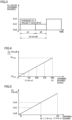
- Fig. 3 is a waveform chart illustrating change of the opening degree of the electronic expansion valve.
- the horizontal axis represents time
- the vertical axis represents the Cv value corresponding to the opening degree of the electronic expansion valve.
- the Cv value represents the valve capacity coefficient.
- controller 200 adjusts time durations tA, tB in Fig. 3 such that the Cv value of LEV 111 reaches a desired Cv value. More specifically, the Cv value varies depending on the time ratio (tA/tC or tB/tC), and therefore, controller 200 changes the time ratio to obtain a desired Cv value.
- Fig. 4 illustrates a relation between the Cv value of LEV 111 and the number of pulses representing the opening degree of LEV 111.
- Controller 200 outputs, to motor drive circuit 203, the number of pulses corresponding to the opening degree of the valve, as a command value.
- the number of pulses can be changed from 0 to n.
- Cvmin the Cv value of the opening degree specified by a command value of 0
- Cvmax the Cv value of the opening degree specified by a command value of 500, which is the maximum number of pulses
- Cvmin may be zero, or may also be a value larger than zero and close to zero.
- Cvmin and Cvmax can be defined appropriately.
- Fig. 5 illustrates respective positions of CvA and CvB in Fig. 3 for respective opening degrees shown in Fig. 4 .
- a command value A corresponding to CvA and a command value B corresponding to CvB are the number of pulses of less than or equal to a quarter (125 for example) of the number of pulses n (500 for example) corresponding to the controllable maximum opening degree.
- the number of pulses B may be set to zero and the number of pulses A may be set to 500 to make tA in Fig. 3 extremely shorter than tB, it is difficult to precisely achieve a desired Cv value, because the response speed of the expansion valve is low and the response speed at which the Cv value is changed in response to change of the opening degree of the expansion valve is low.
- the present embodiment defines command values A, B as having the relation: 0 ⁇ B ⁇ A ⁇ n ⁇ 1/4. Moreover, an excessively long period tC in Fig. 3 makes it impossible to achieve the average value CvC, and therefore, it is desired to set period tC to one minute or less.
- Fig. 6 is a flowchart illustrating control for operating mode switching performed by an air conditioning system according to Embodiment 1.
- step S1 controller 200 determines whether or not the magnitude of the difference between indoor temperature Tr and set temperature Tset is smaller than a reference value Tth1. Thus, the magnitude of the air conditioning load is determined.
- controller 200 determines, in step S2, whether or not the superheat of discharged refrigerant (hereinafter referred to as discharge SH) is smaller than a reference value Tth2. Thus, the state of refrigerant circuit 150 is determined.
- discharge SH superheat of discharged refrigerant
- time ratio tA/tC in Fig. 3 may be a fixed value (50% for example), the time ratio can be changed to change the average opening degree of LEV 111 with finer precision.
- Fig. 7 is a flowchart showing an example of the details of the process in step S3 of Fig. 6 .
- controller 200 determines whether or not discharge SH is smaller than reference value Tth2.
- controller 200 When discharge SH ⁇ Tth2 is satisfied (YES in S11), controller 200 reduces, in step S12, the duration of time tA in which the opening degree of the LEV is high first opening degree CvA to thereby reduce time ratio tA/tC. The operation in step S11 is then performed again.
- the initial value of the time ratio in step S12 may be set to 100%, so that the time ratio is adjusted to set discharge SH to a desired value and, after the time ratio is adjusted (YES in S11), the LEV opening degree H/L repetitive operation is performed for a certain time at the time ratio fixed to the adjusted time ratio (S13).
- Embodiment 1 enables control of LEV 111 which is set to the narrowed state corresponding to the low-opening-degree region (the region of 1/4 or less of the upper limit opening degree) in which the proper relation between a pulse command value and the opening degree of LEV 111 or the Cv value is difficult to achieve.
- the low capacity operation where the operating frequency of the compressor is set low is facilitated.
- the time ratio is changed while detecting the value of discharge SH, to determine a proper time ratio.
- a refrigeration cycle apparatus is described that is characterized by: storing, in memory 202 of controller 200, the Cv value of the expansion valve for making discharge SH more than or equal to a specified value based on the indoor and outdoor temperatures, measuring the indoor and outdoor temperatures, and adjusting the time ratio of the opening degree of LEV 111 within a certain time based on the measured temperatures, to thereby obtain a desired Cv value (CvC).
- Fig. 8 is a flowchart illustrating a process performed in Embodiment 2.
- Fig. 8 shows the process of step S3A performed in Embodiment 2 instead of step S3 shown in Fig. 7 .
- controller 200 obtains outdoor temperature Te from temperature sensor 103 and obtains indoor temperature Tr from temperature sensor 102.
- controller 200 determines the Cv value from a map M1 stored in advance in memory 202, and calculates the time ratio corresponding to the Cv value determined in step S23.
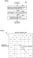
- Fig. 9 shows an example of map M1 used in Embodiment 2.
- the Cv value corresponding to the expansion valve opening degree associated with a respective combination of the indoor temperature and the outdoor temperature is stored, in the form of a table, in memory 202 incorporated in controller 200.
- Controller 200 measures the indoor and outdoor air temperatures Tr and Te with temperature sensors 102 and 103 such as thermistor, and calculates the time ratio implementing the Cv value appropriate for the air temperature, to control LEV 111.
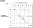
- Fig. 10 shows another map M1A used in Embodiment 2.
- the higher the outdoor temperature and the lower the indoor temperature the direction toward the upper left in Fig. 9
- the Cv value decreases and, the lower the outdoor temperature and the higher the indoor temperature (the direction toward the lower right in Fig. 9 ), the Cv value increases.
- the Cv value can be reduced by increasing time tB in Fig. 3 and increasing the time ratio (tB/tC in Fig. 3 ). Therefore, in map M1A of Fig.
- the time ratio can be used to control LEV 111, similarly to Embodiment 1, so that the Cv value of a small opening degree which is difficult to control can be implemented by the average time and thereby ensure adequate discharge SH.
- a desired Cv value which varies depending on the indoor and outdoor air temperatures is stored in the form of a table in memory 202 in advance, and therefore, for the actual products, the time ratio can be determined immediately by merely measuring the indoor and outdoor temperatures by temperature sensors 102 and 103, and accordingly, more speedy control can be implemented.
- Embodiment 3 is characterized by adjusting the time ratio (tB/tC in Fig. 3 ) of the opening degree of LEV 111 within a certain time, based on the operating frequency of compressor 10, to thereby obtain a desired Cv value (CvC).
- Fig. 11 shows a relation between the operating frequency of the compressor and the desired Cv value.
- the desired Cv value is also increased, as shown in Fig. 11 .
- the opening degree of the expansion valve having a small Cv value is difficult to control. Therefore, in Embodiment 3, at a frequency where a small Cv value is required, the time ratio shown in Fig. 3 is changed to obtain the desired Cv value.
- Fig. 12 illustrates control of the time ratio performed in Embodiment 3.
- the time ratio (tB/tC) of the expansion valve opening degree associated with each operating frequency of compressor 10 is stored, in the form of a table, in memory 202 incorporated in controller 200.
- Controller 200 calls, from memory 202, the time ratio associated with the operating frequency to perform control.
- the time ratio is tA/tC, and therefore, a time ratio of 100% is a state in which the large opening degree continues.
- the time ratio is tB/tC and therefore, a time ratio of 0% is the state in which the large opening degree continues.
- Fig. 12 while the operating frequency falls in the range from fth to fmax, LEV 111 is continuously operated at a single opening degree command value, like the normal control and, when the operating frequency becomes less than or equal to fth, the first opening degree (corresponding to CvA) and the second opening degree (corresponding to CvB) are repeated. As the operating frequency decreases from fth to fmin, the time ratio tB/tC increases and the Cv value decreases.
- the opening degree command value is controlled such that the opening degree of LEV 111 is repeated between the first opening degree and the second opening degree at a certain time ratio, similarly to Embodiment 1.
- the Cv value in the region smaller than the minimum Cv value that can be controlled stably can be implemented by the time average, so that adequate discharge SH can be ensured.
- the desired Cv value that varies depending on the operating frequency can be stored in the form of a table in advance, and therefore, for the actual products, better control can be implemented by merely reading the time ratio associated with the frequency.
- Embodiment 4 is characterized by combining Embodiments 1 to 3 to control LEV 111 based on the time ratio associated with the indoor air temperature, the outdoor air temperature, and the operating frequency.
- Fig. 13 is a flowchart illustrating control for operating mode switching performed by an air conditioning system according to Embodiment 4.
- the flowchart of Fig. 13 corresponds to the flowchart of Fig. 6 except that step S2A is added after step S2 and step S3B is performed instead of step S3.
- controller 200 determines whether or not the magnitude of the difference between indoor temperature Tr and set temperature Tset is smaller than reference value Tth1. Thus, the magnitude of the air conditioning load is determined.
- controller 200 determines in step S2 whether or not discharge SH is smaller than reference value Tth2. Thus, the state of refrigerant circuit 150 is determined.
- controller 200 determines, in step S2A, whether or not operating frequency f of compressor 10 is lower than a reference value fth. Thus, it is determined whether or not a frequency range of fmin to fth is obtained for which the time ration control as shown in Fig. 12 is introduced.
- Fig. 14 is a flowchart illustrating the process in step S3B in Fig. 13 .
- controller 200 obtains outdoor temperature Te from temperature sensor 103 and obtains indoor temperature Tr from temperature sensor 102, and further obtains operating frequency f from a control process routine of compressor 10.
- controller 200 determines the Cv value from a map M2 stored in advance in memory 202 and, in step S33, calculates the time ratio corresponding to the determined Cv value.
- Fig. 15 shows an example of map M2 used in Embodiment 4.
- the Cv value corresponding to the expansion valve opening degree associated with the combination of the indoor and outdoor temperatures and the operating frequency is stored in the form of a table in memory 202 incorporated in controller 200.
- Controller 200 calculates the time ratio that implements the Cv value associated with air temperatures Tr, Te and operating frequency f to control LEV 111.
- the time ratio associated with the air temperatures may directly be stored, instead of the Cv value.
- the Cv value of the expansion valve opening degree or the time ratio associated with air temperatures Tr, Te and operating frequency f is stored in the form of a table in memory 202. Controller 200 calls, from memory 202, the Cv value or the time ratio associated with air temperatures Tr, Te and operating frequency f during operation, to control LEV 111.
- the opening degree command value is controlled such that the opening degree of LEV 111 is repeated between the first opening degree and the second opening degree at a certain time ratio, similarly to Embodiment 1.
- the Cv value in the region smaller than the minimum Cv value that can be controlled stably can be implemented by the time average, so that adequate discharge SH can be ensured.
- Embodiment 2 and Embodiment 3 can be combined to implement still better control.
- Air conditioning apparatus 1 of the present embodiment includes refrigerant circuit 150 and controller 200.
- Refrigerant circuit 150 is configured to allow refrigerant to circulate through compressor 10, condenser 40, 20, LEV 111, and evaporator 20, 40.
- LEV 111 has an opening degree variable from a lower limit opening degree to an upper limit opening degree.
- Controller 200 is configured to control LEV 111 to alternately repeat a first opening degree CvA and a second opening degree CvB in a range of less than or equal to a quarter of the upper limit opening degree, second opening degree CvB being smaller than first opening degree CvA.
- controller 200 specifies a plurality of opening degrees from the lower limit opening degree Cvmin to the upper limit opening degree Cvmax, by respective command values from 0 to n, where n is a natural number. Controller 200 outputs the command values to alternately repeat a first command value A and a second command value B in a range of less than or equal to a quarter of n, the second command value being smaller than the first command value.
- air conditioning apparatus 1 further includes: outdoor unit 2 containing one of condenser 40, 20 and evaporator 20, 40 and containing the compressor; and indoor unit 3 containing the other one of condenser 40, 20 and evaporator 20, 40.
- Controller 200 controls LEV 111 to alternately repeat first opening degree CvB and second opening degree CvA, when a low-capacity operating condition including a first condition is satisfied, the first condition being a condition that a magnitude of a difference between set temperature Tset and temperature Tr of air sucked into indoor unit 3 is smaller than threshold value Tth1 ( Fig. 6 , YES in S1).
- the low-capacity operating condition is satisfied, when the first condition is satisfied and a second condition is satisfied, the second condition being a condition that a value of superheat of the refrigerant discharged from compressor 10 is less than or equal to a specified value Tth2 ( Fig. 6 , YES in S2).
- controller 200 adjusts a time ratio between the first opening degree and the second opening degree in a period that are alternately repeated, to cause the value of superheat to approach specified value Tth2.
- controller 200 includes processor 201 and memory 202.
- Memory 202 stores a map as shown in Fig. 9 , input data to the map is an indoor temperature and an outdoor air temperature, and output data from the map is a time ratio between the first opening degree and the second opening degree in a period that are alternately repeated, or the output data is a capacity coefficient (Cv value) of LEV 111 corresponding to the time ratio.
- Processor 201 controls LEV 111 using the map.
- controller 200 includes processor 201 and memory 202.
- Memory 202 stores a map, input data to the map is an operating frequency of compressor 10, and output data from the map is a time ratio between the first opening degree and the second opening degree in a period that are alternately repeated, or the output data is a capacity coefficient (Cv value) of the expansion valve corresponding to the time ratio.
- Processor 201 controls LEV 111 using the map.
- controller 200 includes processor 201 and memory 202.
- Memory 202 stores a map, as shown in Fig. 15 , input data to the map is an indoor temperature, an outdoor air temperature, and an operating frequency of the compressor, and output data from the map is a time ratio between the first opening degree and the second opening degree in a period that are alternately repeated, or the output data is a capacity coefficient of the expansion valve corresponding to the time ratio.
- Processor 201 controls LEV 111 using the map.
- 1 air conditioning apparatus 2 outdoor unit; 3 indoor unit; 10 compressor; 20, 40 heat exchanger; 90, 92, 94, 96, 97, 99 pipe; 100 four-way valve; 101, 102, 103, 106, 107 temperature sensor; 111 LEV; 112 stepping motor; 113 valve body; 150 refrigerant circuit; 200 controller; 201 processor; 202 memory; 203 motor drive circuit; E, F, G, H, P1, P3, P4 port
Landscapes
- Engineering & Computer Science (AREA)
- Mechanical Engineering (AREA)
- General Engineering & Computer Science (AREA)
- Physics & Mathematics (AREA)
- Thermal Sciences (AREA)
- Chemical & Material Sciences (AREA)
- Combustion & Propulsion (AREA)
- Signal Processing (AREA)
- Fuzzy Systems (AREA)
- Mathematical Physics (AREA)
- Air Conditioning Control Device (AREA)
Abstract
Description
- The present disclosure relates to an air conditioning apparatus.
- In recent years, houses have been increasingly airtight and thermally insulated, aiming at a ZEH (net Zero-Energy House). For highly insulated houses, the rated capacity sufficient for the floor area is still required during air conditioning in midsummer and midwinter, while the air conditioning load when the room temperature is stable is extremely small.
- In order to implement stable air conditioning under an extremely small air conditioning load, an air conditioning apparatus may be operated with a low frequency of its compressor. A lower frequency of the compressor, however, results in a smaller difference between high and low pressures in a refrigerant circuit and a lower temperature and a lower superheat of discharged refrigerant. The lower superheat of discharged refrigerant causes a lower temperature and a lower superheat of sucked refrigerant, which is likely to cause a liquid-gas two-phase state of the refrigerant sucked into the compressor. Such a state may lead to failure of the compressor. While the state of the sucked refrigerant may usually be converted from the two-phase state to a single gas phase by narrowing the opening of an electronic expansion valve, it has been difficult to precisely control the electronic expansion valve, particularly when the valve has a small opening degree, due to manufacture variation of the electronic expansion valve.
-
WO2013/103061 (PTL 1) discloses an electronic expansion valve with an attached barcode representing property data reflecting manufacture variation, in order to stabilize air conditioning control, as well as an air conditioning apparatus including the electronic expansion valve. - PTL 1:
WO2013/103061 - For the electronic expansion valve disclosed in
WO2013/103061 (PTL 1), the valve opening point of each electronic expansion valve is measured in advance and its data is recorded in the form of a barcode, in order to correct for the manufacture variation of the valve opening point. During manufacture of an air conditioning apparatus, it is necessary to read the barcode and reflect the read data on a control program for the electronic expansion valve. This, however, results in increase of the manufacturing steps for the air conditioning apparatus. - The present disclosure is made in order to solve the problem as described above, and its object is to disclose an air conditioning apparatus that can implement a low-capacity operation, while avoiding complication of the manufacturing steps.
- The present disclosure relates to an air conditioning apparatus. The air conditioning apparatus includes a refrigerant circuit and a controller. The refrigerant circuit is configured to allow refrigerant to circulate through a compressor, a condenser, an expansion valve, and an evaporator. The expansion valve has an opening degree variable from a lower limit opening degree to an upper limit opening degree. The controller is configured to control the expansion valve to alternately repeat a first opening degree and a second opening degree in a range of less than or equal to a quarter of the upper limit opening degree, where the second opening degree is smaller than the first opening degree.
- The air conditioning apparatus of the present disclosure repeatedly increases and decreases the opening degree of the expansion valve, in a range of less than or equal to a quarter of the upper limit opening degree. Thus, the air conditioning apparatus capable of low-capacity operation while avoiding complication of the manufacturing steps can be implemented.
-
-
Fig. 1 shows a configuration of an air conditioning apparatus according toEmbodiment 1. -
Fig. 2 is a block diagram showing configurations of a controller and an LEV. -
Fig. 3 is a waveform chart illustrating change of the opening degree of an electronic expansion valve. -
Fig. 4 illustrates a relation between the Cv value ofLEV 111 and the number of pulses representing the opening degree ofLEV 111. -
Fig. 5 illustrates respective positions of CvA and CvB inFig. 3 for respective opening degrees shown inFig. 4 . -
Fig. 6 is a flowchart illustrating control for operating mode switching performed by an air conditioning system according toEmbodiment 1. -
Fig. 7 is a flowchart showing an example of details of a process in step S3 ofFig. 6 . -
Fig. 8 is a flowchart illustrating a process performed inEmbodiment 2. -
Fig. 9 shows an example of a map M1 used in Embodiment 2. -
Fig. 10 shows another map M1A used in Embodiment 2. -
Fig. 11 shows a relation between the operating frequency of a compressor and a desired Cv value. -
Fig. 12 illustrates control of a time ratio performed inEmbodiment 3. -
Fig. 13 is a flowchart illustrating control for operating mode switching performed by an air conditioning system according to Embodiment 4. -
Fig. 14 is a flowchart illustrating a process in step S3B ofFig. 13 . -
Fig. 15 shows an example of a map M2 used in Embodiment 4. - Embodiments of the present disclosure are hereinafter described in detail with reference to the drawings. In the following, a plurality of embodiments are described, and it is originally intended that characteristics described in connection with the embodiments each are combined as appropriate. In the drawings, the same or corresponding parts are denoted by the same reference characters, and a description thereof is not herein repeated. In the following drawings, the relation between components in terms of the size may be different from the actual one.
-
Fig. 1 shows a configuration of an air conditioning apparatus according toEmbodiment 1.Air conditioning apparatus 1 includes arefrigerant circuit 150, andrefrigerant circuit 150 includes acompressor 10, anindoor heat exchanger 20, an electronic expansion valve (LEV: Linear Expansion Valve) 111, anoutdoor heat exchanger 40,pipes way valve 100. Four-way valve 100 has ports E to H. - Pipe 90 is connected between port H of four-
way valve 100 and a port P1 ofindoor heat exchanger 20. Pipe 92 is connected between a port P4 ofindoor heat exchanger 20 and LEV 111. Pipe 94 is connected between LEV 111 and a port P3 ofoutdoor heat exchanger 40. - Pipe 96 is connected between a port P2 of
outdoor heat exchanger 40, and port F of four-way valve 100. Pipe 97 is connected between a suction port ofcompressor 10 and port E of four-way valve 100. Pipe 99 is connected between a discharge port ofcompressor 10 and port G of four-way valve 100. -
Compressor 10, LEV 111,outdoor heat exchanger 40,pipes way valve 100 are contained inoutdoor unit 2.Indoor heat exchanger 20 is contained inindoor unit 3.Outdoor unit 2 andindoor unit 3 are connected to each other throughpipes -
Air conditioning apparatus 1 further includestemperature sensors 101 to 103, 106, 107, and acontroller 200.Temperature sensor 101 is placed onpipe 99 to measure a discharge temperature TH.Temperature sensor 102 is placed nearindoor heat exchanger 20 to measure an indoor temperature Tr.Temperature sensor 103 is placed nearoutdoor heat exchanger 40 to measure an outdoor temperature Te. Temperature sensor 106 is placed on a refrigerant pipe ofindoor heat exchanger 20 to measure a temperature T1 of refrigerant in the two-phase region.Temperature sensor 107 is placed on a refrigerant pipe ofoutdoor heat exchanger 40 to measure a temperature T2 of refrigerant in the two-phase region. In accordance with an operation command signal provided from a user and outputs of various sensors,controller 200controls compressor 10, four-way valve 100, andLEV 111. -
Compressor 10 is configured to change its operating frequency, in accordance with a control signal received fromcontroller 200. Specifically,compressor 10 includes therein a drive motor variable in rotational speed under inverter control and, when the operating frequency is changed, the rotational speed of the drive motor is changed. The operating frequency ofcompressor 10 is changed so as to adjust the output ofcompressor 10.Compressor 10 of any of various types such as rotary type, reciprocating type, scroll type, and screw type, for example, may be employed. - Four-
way valve 100 is controlled into one of a cooling operation state and a heating operation state, by a control signal received fromcontroller 200. The cooling operation state refers to a state in which port E and port H communicate with each other and port F and port G communicate with each other. The heating operation state refers to a state in which port E and port F communicate with each other and port H and port G communicate with each other. In the cooling operation state,compressor 10 is operated to cause refrigerant to circulate in the refrigerant circuit in the direction indicated by the solid-line arrows. In the heating operation state,compressor 10 is operated to cause refrigerant to circulate in the refrigerant circuit in the direction indicated by the broken-line arrows. -
LEV 111 has its opening degree controlled to adjust the SH (superheat) of refrigerant at an outlet of an evaporator, by a control signal received fromcontroller 200. -
Fig. 2 is a block diagram showing configurations of the controller and the LEV. As shown inFig. 2 ,controller 200 has a configuration including a CPU (Central Processing Unit) 201, a memory 202 (ROM (Read Only Memory) and a RAM (Random Access Memory)), and an input/output buffer (not shown), for example.CPU 201 deploys and executes, on the RAM for example, programs stored in the ROM. The programs stored in the ROM are programs in which a process procedure forcontroller 200 is specified. In accordance with these programs,controller 200 performs control of each device inair conditioning apparatus 1. This control is not limited to processing by software, but may be performed by dedicated hardware (electronic circuit). -
Controller 200 is configured to control amotor drive circuit 203 based on outdoor temperature Te, indoor temperature Tr, discharge temperature TH, andtemperatures T 1, T2 of refrigerant in the two-phase region. -
LEV 111 includes a steppingmotor 112 and avalve body 113 having its opening degree varied in response to change of the needle position caused by rotation of steppingmotor 112. Steppingmotor 112 is driven bymotor drive circuit 203.Controller 200 outputs, tomotor drive circuit 203, the number of pulses as a command value representing the opening degree ofvalve body 113. - Referring again to
Fig. 1 , flow of refrigerant indicated by the broken-line arrows during heating operation is described. Gas refrigerant discharged fromcompressor 10 flows throughpipe 90 intoindoor heat exchanger 20. The gas refrigerant enteringindoor heat exchanger 20 exchanges heat with air flowing on the fin side ofindoor heat exchanger 20 to be converted into liquid refrigerant. The liquefied refrigerant flows throughpipe 92 intoLEV 111 and undergoes adiabatic expansion. - The gas-liquid two-phase refrigerant having undergone adiabatic expansion in
LEV 111 flows throughpipe 94 intooutdoor heat exchanger 40. The gas-liquid two-phase refrigerant enteringoutdoor heat exchanger 40 exchanges heat with air flowing on the fin side ofoutdoor heat exchanger 40 to be converted into gas refrigerant. The gasified refrigerant flows throughpipe 96, four-way valve 100, andpipe 97 and returns tocompressor 10. - A case where the air conditioning load decreases and the operating frequency of
compressor 10 decreases, for example, is described. - When the air conditioning load is small,
controller 200 lowers the operating frequency ofcompressor 10 until the air conditioning capacity matches the air conditioning load. When the operating frequency ofcompressor 10 decreases, the amount of refrigerant circulating inrefrigerant circuit 150 decreases. As the amount of circulating refrigerant decreases, the air conditioning capacity (= amount of circulating refrigerant × indoor-unit enthalpy difference) decreases. - As the operating frequency of
compressor 10 decreases, the pressure difference generated incompressor 10 decreases, resulting in a smaller temperature difference between the refrigerant temperature and the air temperature inindoor heat exchanger 20 andoutdoor heat exchanger 40. The decrease of the temperature difference causes less heat exchange and hence less increase of the discharge temperature, resulting in decrease of the superheat of discharged refrigerant. - In view of the above,
controller 200 performs control to narrow the opening ofLEV 111 and thereby ensure an adequate pressure difference, in order to ensure an adequate temperature difference. - When
compressor 10 is operated at a reduced frequency in order to precisely implement a low output of 1 kW or less of the air conditioning capacity, however, it is required to precisely control the opening degree ofLEV 111 into a smaller opening degree. In this case, it is required to reduce the number of pulses representing the opening degree to be transmitted as a command fromcontroller 200 tomotor drive circuit 203. The valve opening point at which the electronic expansion valve transitions from the closed state to the opened state is different for each electronic expansion valve. Such a difference in valve opening point is caused by a difference in the manner of attaching the stepping motor, the size of the valve body, and the size of the valve seat. Use in a region where the number of pulses is small is therefore not recommended, because an unintended valve opening state may be generated due to manufacture variation of the valve opening point. -
WO2013/103061 therefore discloses that the properties of the expansion valve are measured individually in advance and data of the valve opening point is provided in the form of a barcode. Individual measurement in advance of the properties of the expansion valve and/or registration of the properties of the expansion valve in the controller of the air conditioning apparatus, however, increases the manufacturing steps. - According to the present embodiment, when the opening degree of
LEV 111 has been decreased to a certain opening degree close to the lower limit at which stable use is possible, and the superheat of discharged refrigerant is insufficient,LEV 111 is fully closed or set to a second opening degree close to the fully closed state and thereafter the opening degree is increased to a first opening, and this is repeated. -
Fig. 3 is a waveform chart illustrating change of the opening degree of the electronic expansion valve. InFig. 3 , the horizontal axis represents time, and the vertical axis represents the Cv value corresponding to the opening degree of the electronic expansion valve. The Cv value represents the valve capacity coefficient. - When a time duration during which the opening degree of
LEV 111 is set to a first opening degree (Cv value = CvA), and a time duration during which the opening degree ofLEV 111 is set to a second opening degree (Cv value = CvB), at a certain time ratio in a period tC are repeated, any average opening degree (Cv value = CvC) between the first opening degree and the second opening degree can be achieved, depending on the time ratio. - In order to achieve a desired superheat of discharged refrigerant while the air conditioning load is small,
controller 200 adjusts time durations tA, tB inFig. 3 such that the Cv value ofLEV 111 reaches a desired Cv value. More specifically, the Cv value varies depending on the time ratio (tA/tC or tB/tC), and therefore,controller 200 changes the time ratio to obtain a desired Cv value. -
Fig. 4 illustrates a relation between the Cv value ofLEV 111 and the number of pulses representing the opening degree ofLEV 111.Controller 200 outputs, tomotor drive circuit 203, the number of pulses corresponding to the opening degree of the valve, as a command value. The number of pulses can be changed from 0 to n. The number of n varies depending on the specification, for example, of the electronic expansion valve, and this number in the example ofFig. 4 , for example, is n = 500, and 1/4 × n = 125. It is supposed that the Cv value of the opening degree specified by a command value of 0 is Cvmin, and the Cv value of the opening degree specified by a command value of 500, which is the maximum number of pulses, is Cvmax. Then, Cvmin may be zero, or may also be a value larger than zero and close to zero. As long as Cvmin < Cvmax is satisfied, Cvmin and Cvmax can be defined appropriately. -
Fig. 5 illustrates respective positions of CvA and CvB inFig. 3 for respective opening degrees shown inFig. 4 . InFig. 5 , it is illustrated that both a command value A corresponding to CvA and a command value B corresponding to CvB are the number of pulses of less than or equal to a quarter (125 for example) of the number of pulses n (500 for example) corresponding to the controllable maximum opening degree. - As shown in
Fig. 3 , the opening degree of the expansion valve corresponding to the Cv value = CvC achieved by controlling the pulses is used when the air conditioning load is extremely small, and is used when there is a possibility that open-valve state occurs unintentionally due to variation of the valve opening point of the expansion valve. Therefore, when the number of pulses A, B is larger than 1/4 of n, such Cv value cannot be achieved. - For example, although the number of pulses B may be set to zero and the number of pulses A may be set to 500 to make tA in
Fig. 3 extremely shorter than tB, it is difficult to precisely achieve a desired Cv value, because the response speed of the expansion valve is low and the response speed at which the Cv value is changed in response to change of the opening degree of the expansion valve is low. - In view of the above, the present embodiment defines command values A, B as having the relation: 0 ≤ B < A ≤ n × 1/4. Moreover, an excessively long period tC in
Fig. 3 makes it impossible to achieve the average value CvC, and therefore, it is desired to set period tC to one minute or less. -
Fig. 6 is a flowchart illustrating control for operating mode switching performed by an air conditioning system according toEmbodiment 1. - In step S1,
controller 200 determines whether or not the magnitude of the difference between indoor temperature Tr and set temperature Tset is smaller than a reference value Tth1. Thus, the magnitude of the air conditioning load is determined. - When |t-Tset| < Tth1 is satisfied (YES in S1),
controller 200 determines, in step S2, whether or not the superheat of discharged refrigerant (hereinafter referred to as discharge SH) is smaller than a reference value Tth2. Thus, the state ofrefrigerant circuit 150 is determined. - When discharge SH < Tth2 is satisfied (YES in S2),
controller 200 repeatedly outputs, in step S3, command values A and B as described above with reference toFigs. 3 to 5 , to thereby controlLEV 111, such that the opening degree ofLEV 111 regularly repeats H (first opening degree, CV value = CvA) and L (second opening degree, Cv value = CvB). Thus, the opening degree of the average Cv value = CvC is achieved. - In contrast, when |t-Tset| ≥ Tth1 is satisfied (NO in S1) or discharge SH ≥ Tth2 is satisfied (NO in S2), normal control for specifying the opening degree of
LEV 111 by one command value is performed in step S4. - While the time ratio tA/tC in
Fig. 3 may be a fixed value (50% for example), the time ratio can be changed to change the average opening degree ofLEV 111 with finer precision. -
Fig. 7 is a flowchart showing an example of the details of the process in step S3 ofFig. 6 . Initially, in step S11,controller 200 determines whether or not discharge SH is smaller than reference value Tth2. - When discharge SH < Tth2 is satisfied (YES in S11),
controller 200 reduces, in step S12, the duration of time tA in which the opening degree of the LEV is high first opening degree CvA to thereby reduce time ratio tA/tC. The operation in step S11 is then performed again. - The initial value of the time ratio in step S12 may be set to 100%, so that the time ratio is adjusted to set discharge SH to a desired value and, after the time ratio is adjusted (YES in S11), the LEV opening degree H/L repetitive operation is performed for a certain time at the time ratio fixed to the adjusted time ratio (S13).
- As described above,
Embodiment 1 enables control ofLEV 111 which is set to the narrowed state corresponding to the low-opening-degree region (the region of 1/4 or less of the upper limit opening degree) in which the proper relation between a pulse command value and the opening degree ofLEV 111 or the Cv value is difficult to achieve. Thus, the low capacity operation where the operating frequency of the compressor is set low is facilitated. - According to
Embodiment 1 as shown inFig. 7 , the time ratio is changed while detecting the value of discharge SH, to determine a proper time ratio. - In connection with
Embodiment 2, a refrigeration cycle apparatus is described that is characterized by: storing, inmemory 202 ofcontroller 200, the Cv value of the expansion valve for making discharge SH more than or equal to a specified value based on the indoor and outdoor temperatures, measuring the indoor and outdoor temperatures, and adjusting the time ratio of the opening degree ofLEV 111 within a certain time based on the measured temperatures, to thereby obtain a desired Cv value (CvC). - The flow and the state of refrigerant in the refrigeration cycle apparatus are similar to those of
Embodiment 1, and therefore, the description thereof is not herein repeated. -
Fig. 8 is a flowchart illustrating a process performed inEmbodiment 2.Fig. 8 shows the process of step S3A performed inEmbodiment 2 instead of step S3 shown inFig. 7 . - Initially, in step S21,
controller 200 obtains outdoor temperature Te fromtemperature sensor 103 and obtains indoor temperature Tr fromtemperature sensor 102. In step S22,controller 200 determines the Cv value from a map M1 stored in advance inmemory 202, and calculates the time ratio corresponding to the Cv value determined in step S23. -
Fig. 9 shows an example of map M1 used inEmbodiment 2. As shown inFig. 9 , the Cv value corresponding to the expansion valve opening degree associated with a respective combination of the indoor temperature and the outdoor temperature is stored, in the form of a table, inmemory 202 incorporated incontroller 200.Controller 200 measures the indoor and outdoor air temperatures Tr and Te withtemperature sensors LEV 111. - While the map in
Fig. 9 stores the Cv value, the time ratio associated with the air temperatures may be stored directly instead of the Cv value.Fig. 10 shows another map M1A used inEmbodiment 2. InFig. 9 , the higher the outdoor temperature and the lower the indoor temperature (the direction toward the upper left inFig. 9 ), the Cv value decreases and, the lower the outdoor temperature and the higher the indoor temperature (the direction toward the lower right inFig. 9 ), the Cv value increases. Thus, the Cv value can be reduced by increasing time tB inFig. 3 and increasing the time ratio (tB/tC inFig. 3 ). Therefore, in map M1A ofFig. 10 , the higher the outdoor temperature and the lower the indoor temperature (the direction toward the upper left inFig. 10 ), time ratio RB (= tB/tC) increases and, the lower the outdoor temperature and the higher the indoor temperature (the direction toward the lower right inFig. 10 ), time ratio RB decreases. - According to
Embodiment 2, the time ratio can be used to controlLEV 111, similarly toEmbodiment 1, so that the Cv value of a small opening degree which is difficult to control can be implemented by the average time and thereby ensure adequate discharge SH. Further, a desired Cv value which varies depending on the indoor and outdoor air temperatures is stored in the form of a table inmemory 202 in advance, and therefore, for the actual products, the time ratio can be determined immediately by merely measuring the indoor and outdoor temperatures bytemperature sensors -
Embodiment 3 is characterized by adjusting the time ratio (tB/tC inFig. 3 ) of the opening degree ofLEV 111 within a certain time, based on the operating frequency ofcompressor 10, to thereby obtain a desired Cv value (CvC). - The flow and the state of refrigerant in the refrigeration cycle apparatus under general control are similar to those of
Embodiment 1, and therefore, the description thereof is not herein repeated. -
Fig. 11 shows a relation between the operating frequency of the compressor and the desired Cv value. Generally, as the operating frequency is increased, the desired Cv value is also increased, as shown inFig. 11 . As described above in connection withEmbodiment 1, the opening degree of the expansion valve having a small Cv value is difficult to control. Therefore, inEmbodiment 3, at a frequency where a small Cv value is required, the time ratio shown inFig. 3 is changed to obtain the desired Cv value. -
Fig. 12 illustrates control of the time ratio performed inEmbodiment 3. According toEmbodiment 3, the time ratio (tB/tC) of the expansion valve opening degree associated with each operating frequency ofcompressor 10 is stored, in the form of a table, inmemory 202 incorporated incontroller 200.Controller 200 calls, frommemory 202, the time ratio associated with the operating frequency to perform control. - According to
Embodiment 1, the time ratio is tA/tC, and therefore, a time ratio of 100% is a state in which the large opening degree continues. In contrast, inFig. 12 , the time ratio is tB/tC and therefore, a time ratio of 0% is the state in which the large opening degree continues. - Therefore, in
Fig. 12 , while the operating frequency falls in the range from fth to fmax,LEV 111 is continuously operated at a single opening degree command value, like the normal control and, when the operating frequency becomes less than or equal to fth, the first opening degree (corresponding to CvA) and the second opening degree (corresponding to CvB) are repeated. As the operating frequency decreases from fth to fmin, the time ratio tB/tC increases and the Cv value decreases. - According to
Embodiment 3, the opening degree command value is controlled such that the opening degree ofLEV 111 is repeated between the first opening degree and the second opening degree at a certain time ratio, similarly toEmbodiment 1. Thus, the Cv value in the region smaller than the minimum Cv value that can be controlled stably can be implemented by the time average, so that adequate discharge SH can be ensured. Further, the desired Cv value that varies depending on the operating frequency can be stored in the form of a table in advance, and therefore, for the actual products, better control can be implemented by merely reading the time ratio associated with the frequency. -
Embodiment 4 is characterized by combiningEmbodiments 1 to 3 to controlLEV 111 based on the time ratio associated with the indoor air temperature, the outdoor air temperature, and the operating frequency. - The general flow and state of refrigerant in the refrigeration cycle apparatus are similar to those of
Embodiment 1, and therefore, the description thereof is not herein repeated. -
Fig. 13 is a flowchart illustrating control for operating mode switching performed by an air conditioning system according toEmbodiment 4. The flowchart ofFig. 13 corresponds to the flowchart ofFig. 6 except that step S2A is added after step S2 and step S3B is performed instead of step S3. - Initially, in step S1,
controller 200 determines whether or not the magnitude of the difference between indoor temperature Tr and set temperature Tset is smaller than reference value Tth1. Thus, the magnitude of the air conditioning load is determined. - When |t-Tset| < Tth1 is satisfied (YES in S1),
controller 200 determines in step S2 whether or not discharge SH is smaller than reference value Tth2. Thus, the state ofrefrigerant circuit 150 is determined. - When discharge SH < Tth2 is satisfied (YES in S2),
controller 200 determines, in step S2A, whether or not operating frequency f ofcompressor 10 is lower than a reference value fth. Thus, it is determined whether or not a frequency range of fmin to fth is obtained for which the time ration control as shown inFig. 12 is introduced. - When f <fth is satisfied (YES in S2A),
controller 200 outputs, in step S3B, command values A and B repeatedly to controlLEV 111, so that the opening degree ofLEV 111 regularly repeats between H (first opening degree, Cv value = CvA) and L (second opening degree, Cv value = CvB). In this way, the opening degree of Cv value = CvC is implemented as an average value. - In contrast, when |t-Tset| ≥ Tth1 is satisfied (NO in S1), or when discharge SH ≥ Tth2 is satisfied (NO in S2) or f ≥ fth is satisfied (NO in S2A), normal control of specifying the opening degree of
LEV 111 by a single command value is performed in step S4. -
Fig. 14 is a flowchart illustrating the process in step S3B inFig. 13 . Initially, in step S31,controller 200 obtains outdoor temperature Te fromtemperature sensor 103 and obtains indoor temperature Tr fromtemperature sensor 102, and further obtains operating frequency f from a control process routine ofcompressor 10. Then, in step S32,controller 200 determines the Cv value from a map M2 stored in advance inmemory 202 and, in step S33, calculates the time ratio corresponding to the determined Cv value. -
Fig. 15 shows an example of map M2 used inEmbodiment 4. As shown inFig. 15 , the Cv value corresponding to the expansion valve opening degree associated with the combination of the indoor and outdoor temperatures and the operating frequency is stored in the form of a table inmemory 202 incorporated incontroller 200.Controller 200 calculates the time ratio that implements the Cv value associated with air temperatures Tr, Te and operating frequency f to controlLEV 111. - While the Cv value is stored in the map of
Fig. 15 , the time ratio associated with the air temperatures may directly be stored, instead of the Cv value. - As described above, in
Embodiment 4, the Cv value of the expansion valve opening degree or the time ratio associated with air temperatures Tr, Te and operating frequency f is stored in the form of a table inmemory 202.Controller 200 calls, frommemory 202, the Cv value or the time ratio associated with air temperatures Tr, Te and operating frequency f during operation, to controlLEV 111. - According to
Embodiment 4, the opening degree command value is controlled such that the opening degree ofLEV 111 is repeated between the first opening degree and the second opening degree at a certain time ratio, similarly toEmbodiment 1. Thus, the Cv value in the region smaller than the minimum Cv value that can be controlled stably can be implemented by the time average, so that adequate discharge SH can be ensured. Further,Embodiment 2 andEmbodiment 3 can be combined to implement still better control. -
Air conditioning apparatus 1 of the present embodiment includesrefrigerant circuit 150 andcontroller 200.Refrigerant circuit 150 is configured to allow refrigerant to circulate throughcompressor 10,condenser LEV 111, andevaporator LEV 111 has an opening degree variable from a lower limit opening degree to an upper limit opening degree.Controller 200 is configured to controlLEV 111 to alternately repeat a first opening degree CvA and a second opening degree CvB in a range of less than or equal to a quarter of the upper limit opening degree, second opening degree CvB being smaller than first opening degree CvA. - Preferably,
controller 200 specifies a plurality of opening degrees from the lower limit opening degree Cvmin to the upper limit opening degree Cvmax, by respective command values from 0 to n, where n is a natural number.Controller 200 outputs the command values to alternately repeat a first command value A and a second command value B in a range of less than or equal to a quarter of n, the second command value being smaller than the first command value. - Preferably,
air conditioning apparatus 1 further includes:outdoor unit 2 containing one ofcondenser evaporator indoor unit 3 containing the other one ofcondenser evaporator Controller 200 controlsLEV 111 to alternately repeat first opening degree CvB and second opening degree CvA, when a low-capacity operating condition including a first condition is satisfied, the first condition being a condition that a magnitude of a difference between set temperature Tset and temperature Tr of air sucked intoindoor unit 3 is smaller than threshold value Tth1 (Fig. 6 , YES in S1). - More preferably, the low-capacity operating condition is satisfied, when the first condition is satisfied and a second condition is satisfied, the second condition being a condition that a value of superheat of the refrigerant discharged from
compressor 10 is less than or equal to a specified value Tth2 (Fig. 6 , YES in S2). - Still more preferably, as shown in
Fig. 7 ,controller 200 adjusts a time ratio between the first opening degree and the second opening degree in a period that are alternately repeated, to cause the value of superheat to approach specified value Tth2. - Preferably,
controller 200 includesprocessor 201 andmemory 202.Memory 202 stores a map as shown inFig. 9 , input data to the map is an indoor temperature and an outdoor air temperature, and output data from the map is a time ratio between the first opening degree and the second opening degree in a period that are alternately repeated, or the output data is a capacity coefficient (Cv value) ofLEV 111 corresponding to the time ratio.Processor 201 controlsLEV 111 using the map. - Preferably,
controller 200 includesprocessor 201 andmemory 202.Memory 202 stores a map, input data to the map is an operating frequency ofcompressor 10, and output data from the map is a time ratio between the first opening degree and the second opening degree in a period that are alternately repeated, or the output data is a capacity coefficient (Cv value) of the expansion valve corresponding to the time ratio.Processor 201 controlsLEV 111 using the map. - Preferably,
controller 200 includesprocessor 201 andmemory 202.Memory 202 stores a map, as shown inFig. 15 , input data to the map is an indoor temperature, an outdoor air temperature, and an operating frequency of the compressor, and output data from the map is a time ratio between the first opening degree and the second opening degree in a period that are alternately repeated, or the output data is a capacity coefficient of the expansion valve corresponding to the time ratio.Processor 201 controlsLEV 111 using the map. - It should be construed that the embodiments disclosed herein are given by way of illustration in all respects, not by way of limitation. It is intended that the scope of the present invention is defined by claims, not by the above description of the embodiments, and encompasses all modifications and variations equivalent in meaning and scope to the claims.
- 1 air conditioning apparatus; 2 outdoor unit; 3 indoor unit; 10 compressor; 20, 40 heat exchanger; 90, 92, 94, 96, 97, 99 pipe; 100 four-way valve; 101, 102, 103, 106, 107 temperature sensor; 111 LEV; 112 stepping motor; 113 valve body; 150 refrigerant circuit; 200 controller; 201 processor; 202 memory; 203 motor drive circuit; E, F, G, H, P1, P3, P4 port
Claims (8)
- An air conditioning apparatus comprising:a refrigerant circuit configured to allow refrigerant to circulate through a compressor, a condenser, an expansion valve, and an evaporator; anda controller configured to control the expansion valve, whereinthe expansion valve has an opening degree variable from a lower limit opening degree to an upper limit opening degree, andthe controller is configured to control the expansion valve to alternately repeat a first opening degree and a second opening degree in a range of less than or equal to a quarter of the upper limit opening degree, the second opening degree being smaller than the first opening degree.
- The air conditioning apparatus according to claim 1, whereinthe controller specifies a plurality of opening degrees from the lower limit opening degree to the upper limit opening degree, by respective command values from 0 to n, where n is a natural number, andthe controller outputs the command values to alternately repeat a first command value and a second command value in a range of less than or equal to a quarter of n, the second command value being smaller than the first command value.
- The air conditioning apparatus according to claim 1, further comprising:an outdoor unit containing one of the condenser and the evaporator and containing the compressor; andan indoor unit containing the other one of the condenser and the evaporator, whereinthe controller controls the expansion valve to alternately repeat the first opening degree and the second opening degree, when a low-capacity operating condition including a first condition is satisfied, the first condition being a condition that a magnitude of a difference between a set temperature and a temperature of air sucked into the indoor unit is smaller than a threshold value.
- The air conditioning apparatus according to claim 3, wherein the low-capacity operating condition is satisfied, when the first condition is satisfied and a second condition is satisfied, the second condition being a condition that a value of superheat of the refrigerant discharged from the compressor is less than or equal to a specified value.
- The air conditioning apparatus according to claim 4, wherein the controller adjusts a time ratio between the first opening degree and the second opening degree in a period that are alternately repeated, to cause the value of superheat to approach the specified value.
- The air conditioning apparatus according to claim 1, whereinthe controller comprises a processor and a memory,the memory stores a map, input data to the map is an indoor temperature and an outdoor air temperature, and output data from the map is a time ratio between the first opening degree and the second opening degree in a period that are alternately repeated, or the output data is a capacity coefficient of the expansion valve corresponding to the time ratio, andthe processor controls the expansion valve using the map.
- The air conditioning apparatus according to claim 1, whereinthe controller comprises a processor and a memory,the memory stores a map, input data to the map is an operating frequency of the compressor, and output data from the map is a time ratio between the first opening degree and the second opening degree in a period that are alternately repeated, or the output data is a capacity coefficient of the expansion valve corresponding to the time ratio, andthe processor controls the expansion valve using the map.
- The air conditioning apparatus according to claim 1, whereinthe controller comprises a processor and a memory,the memory stores a map, input data to the map is an indoor temperature, an outdoor air temperature, and an operating frequency of the compressor, and output data from the map is a time ratio between the first opening degree and the second opening degree in a period that are alternately repeated, or the output data is a capacity coefficient of the expansion valve corresponding to the time ratio, andthe processor controls the expansion valve using the map.
Applications Claiming Priority (1)
| Application Number | Priority Date | Filing Date | Title |
|---|---|---|---|
| PCT/JP2021/005858 WO2022176050A1 (en) | 2021-02-17 | 2021-02-17 | Air-conditioning device |
Publications (2)
| Publication Number | Publication Date |
|---|---|
| EP4296593A1 true EP4296593A1 (en) | 2023-12-27 |
| EP4296593A4 EP4296593A4 (en) | 2024-03-27 |
Family
ID=82930312
Family Applications (1)
| Application Number | Title | Priority Date | Filing Date |
|---|---|---|---|
| EP21926490.0A Withdrawn EP4296593A4 (en) | 2021-02-17 | 2021-02-17 | AIR CONDITIONING DEVICE |
Country Status (4)
| Country | Link |
|---|---|
| US (1) | US20240068699A1 (en) |
| EP (1) | EP4296593A4 (en) |
| JP (1) | JP7466754B2 (en) |
| WO (1) | WO2022176050A1 (en) |
Families Citing this family (2)
| Publication number | Priority date | Publication date | Assignee | Title |
|---|---|---|---|---|
| CN115406133B (en) * | 2021-05-27 | 2024-05-31 | 上海兴邺材料科技有限公司 | Air conditioning system and control method thereof |
| DE102021005724A1 (en) * | 2021-11-18 | 2023-05-25 | Truma Gerätetechnik GmbH & Co. KG | air conditioner |
Family Cites Families (7)
| Publication number | Priority date | Publication date | Assignee | Title |
|---|---|---|---|---|
| JPH05133618A (en) * | 1991-11-12 | 1993-05-28 | Hitachi Ltd | Air conditioner |
| JPH11211286A (en) * | 1998-01-23 | 1999-08-06 | Hitachi Ltd | Air conditioner |
| JP5192883B2 (en) * | 2008-03-31 | 2013-05-08 | 三菱重工業株式会社 | Multi-type air conditioner |
| JP5218694B1 (en) | 2012-01-04 | 2013-06-26 | ダイキン工業株式会社 | Electronic expansion valve and air conditioner equipped with electronic expansion valve |
| WO2016139736A1 (en) * | 2015-03-02 | 2016-09-09 | 三菱電機株式会社 | Control device and method for refrigeration cycle device |
| KR102346627B1 (en) * | 2015-09-30 | 2022-01-05 | 엘지전자 주식회사 | An air conditioning system and a method for controlling the same |
| JP6749133B2 (en) * | 2016-04-22 | 2020-09-02 | 株式会社大気社 | Cooling system |
-
2021
- 2021-02-17 US US18/261,406 patent/US20240068699A1/en not_active Abandoned
- 2021-02-17 JP JP2023500176A patent/JP7466754B2/en active Active
- 2021-02-17 WO PCT/JP2021/005858 patent/WO2022176050A1/en not_active Ceased
- 2021-02-17 EP EP21926490.0A patent/EP4296593A4/en not_active Withdrawn
Also Published As
| Publication number | Publication date |
|---|---|
| EP4296593A4 (en) | 2024-03-27 |
| JP7466754B2 (en) | 2024-04-12 |
| WO2022176050A1 (en) | 2022-08-25 |
| US20240068699A1 (en) | 2024-02-29 |
| JPWO2022176050A1 (en) | 2022-08-25 |
Similar Documents
| Publication | Publication Date | Title |
|---|---|---|
| JP6642379B2 (en) | air conditioner | |
| CN101646911B (en) | Optimization of air cooled chiller system operation | |
| EP2351973B1 (en) | Refrigeration cycle device | |
| CN112283903B (en) | Air conditioner and control method of expansion valve | |
| EP3473946A1 (en) | Multi-split air conditioner control device, multi-split air conditioner, multi-split air conditioner control method, and multi-split air conditioner control program | |
| EP3587948B1 (en) | Air conditioner | |
| WO2008016228A1 (en) | Method for controlling electronic expansion valve of air conditioner | |
| EP4296593A1 (en) | Air-conditioning device | |
| KR20050105873A (en) | Electronic expansion valve open control method for air conditioner | |
| CN116136342B (en) | Electronic expansion valve opening degree adjusting method and device, controller and heat pump host | |
| US7856292B2 (en) | System and method for lowering a temperature of liquid exiting a heat exchanger in a vapor compression system | |
| US11506435B2 (en) | Water regulator | |
| JPWO2017109906A1 (en) | Air conditioner | |
| EP4095454A1 (en) | Air conditioner | |
| JP2000283568A (en) | Refrigeration device control method and refrigeration device | |
| KR101485848B1 (en) | Control method of multi-type air conditioner | |
| CN107894068B (en) | A method and device for adjusting the operating state of an air conditioner | |
| JP4867503B2 (en) | Cooling system | |
| JP7341337B2 (en) | Cold heat source unit, refrigeration cycle equipment, and refrigerator | |
| JP2004324952A (en) | Air conditioner and control method thereof | |
| JP2022069305A (en) | Air conditioner | |
| EP4495506A1 (en) | Refrigeration cycle apparatus | |
| JP7635282B2 (en) | Air Conditioning Equipment | |
| US20250207801A1 (en) | Air conditioner and control method therefor | |
| EP4488597A1 (en) | Refrigeration cycle device |
Legal Events
| Date | Code | Title | Description |
|---|---|---|---|
| STAA | Information on the status of an ep patent application or granted ep patent |
Free format text: STATUS: THE INTERNATIONAL PUBLICATION HAS BEEN MADE |
|
| PUAI | Public reference made under article 153(3) epc to a published international application that has entered the european phase |
Free format text: ORIGINAL CODE: 0009012 |
|
| STAA | Information on the status of an ep patent application or granted ep patent |
Free format text: STATUS: REQUEST FOR EXAMINATION WAS MADE |
|
| 17P | Request for examination filed |
Effective date: 20230810 |
|
| AK | Designated contracting states |
Kind code of ref document: A1 Designated state(s): AL AT BE BG CH CY CZ DE DK EE ES FI FR GB GR HR HU IE IS IT LI LT LU LV MC MK MT NL NO PL PT RO RS SE SI SK SM TR |
|
| A4 | Supplementary search report drawn up and despatched |
Effective date: 20240226 |
|
| RIC1 | Information provided on ipc code assigned before grant |
Ipc: F25B 41/345 20210101ALI20240220BHEP Ipc: F25B 1/00 20060101AFI20240220BHEP |
|
| DAV | Request for validation of the european patent (deleted) | ||
| DAX | Request for extension of the european patent (deleted) | ||
| STAA | Information on the status of an ep patent application or granted ep patent |
Free format text: STATUS: THE APPLICATION HAS BEEN WITHDRAWN |
|
| 18W | Application withdrawn |
Effective date: 20240904 |