EP4296513A2 - Diaphragm pump and pressure regulating apparatus - Google Patents
Diaphragm pump and pressure regulating apparatus Download PDFInfo
- Publication number
- EP4296513A2 EP4296513A2 EP23209763.4A EP23209763A EP4296513A2 EP 4296513 A2 EP4296513 A2 EP 4296513A2 EP 23209763 A EP23209763 A EP 23209763A EP 4296513 A2 EP4296513 A2 EP 4296513A2
- Authority
- EP
- European Patent Office
- Prior art keywords
- pump
- discharge
- passage
- fluid
- pressure
- Prior art date
- Legal status (The legal status is an assumption and is not a legal conclusion. Google has not performed a legal analysis and makes no representation as to the accuracy of the status listed.)
- Pending
Links
- 230000001105 regulatory effect Effects 0.000 title claims description 61
- 239000012530 fluid Substances 0.000 claims abstract description 165
- 230000007423 decrease Effects 0.000 claims description 26
- 238000000034 method Methods 0.000 claims description 22
- 238000011144 upstream manufacturing Methods 0.000 claims description 13
- 230000003247 decreasing effect Effects 0.000 claims description 7
- 238000005192 partition Methods 0.000 description 19
- 230000002093 peripheral effect Effects 0.000 description 9
- 230000001276 controlling effect Effects 0.000 description 8
- 238000009530 blood pressure measurement Methods 0.000 description 7
- 229920001971 elastomer Polymers 0.000 description 3
- 238000004519 manufacturing process Methods 0.000 description 3
- 239000000463 material Substances 0.000 description 3
- 230000013011 mating Effects 0.000 description 3
- 239000005060 rubber Substances 0.000 description 3
- 241001125929 Trisopterus luscus Species 0.000 description 2
- 238000010586 diagram Methods 0.000 description 2
- 230000002123 temporal effect Effects 0.000 description 2
- 239000007788 liquid Substances 0.000 description 1
- 229920003051 synthetic elastomer Polymers 0.000 description 1
- 239000005061 synthetic rubber Substances 0.000 description 1
Images


Classifications
-
- F—MECHANICAL ENGINEERING; LIGHTING; HEATING; WEAPONS; BLASTING
- F04—POSITIVE - DISPLACEMENT MACHINES FOR LIQUIDS; PUMPS FOR LIQUIDS OR ELASTIC FLUIDS
- F04B—POSITIVE-DISPLACEMENT MACHINES FOR LIQUIDS; PUMPS
- F04B43/00—Machines, pumps, or pumping installations having flexible working members
- F04B43/02—Machines, pumps, or pumping installations having flexible working members having plate-like flexible members, e.g. diaphragms
- F04B43/025—Machines, pumps, or pumping installations having flexible working members having plate-like flexible members, e.g. diaphragms two or more plate-like pumping members in parallel
- F04B43/026—Machines, pumps, or pumping installations having flexible working members having plate-like flexible members, e.g. diaphragms two or more plate-like pumping members in parallel each plate-like pumping flexible member working in its own pumping chamber
-
- F—MECHANICAL ENGINEERING; LIGHTING; HEATING; WEAPONS; BLASTING
- F04—POSITIVE - DISPLACEMENT MACHINES FOR LIQUIDS; PUMPS FOR LIQUIDS OR ELASTIC FLUIDS
- F04B—POSITIVE-DISPLACEMENT MACHINES FOR LIQUIDS; PUMPS
- F04B45/00—Pumps or pumping installations having flexible working members and specially adapted for elastic fluids
- F04B45/04—Pumps or pumping installations having flexible working members and specially adapted for elastic fluids having plate-like flexible members, e.g. diaphragms
- F04B45/047—Pumps having electric drive
-
- F—MECHANICAL ENGINEERING; LIGHTING; HEATING; WEAPONS; BLASTING
- F04—POSITIVE - DISPLACEMENT MACHINES FOR LIQUIDS; PUMPS FOR LIQUIDS OR ELASTIC FLUIDS
- F04B—POSITIVE-DISPLACEMENT MACHINES FOR LIQUIDS; PUMPS
- F04B39/00—Component parts, details, or accessories, of pumps or pumping systems specially adapted for elastic fluids, not otherwise provided for in, or of interest apart from, groups F04B25/00 - F04B37/00
- F04B39/10—Adaptations or arrangements of distribution members
-
- F—MECHANICAL ENGINEERING; LIGHTING; HEATING; WEAPONS; BLASTING
- F04—POSITIVE - DISPLACEMENT MACHINES FOR LIQUIDS; PUMPS FOR LIQUIDS OR ELASTIC FLUIDS
- F04B—POSITIVE-DISPLACEMENT MACHINES FOR LIQUIDS; PUMPS
- F04B43/00—Machines, pumps, or pumping installations having flexible working members
- F04B43/0009—Special features
- F04B43/0045—Special features with a number of independent working chambers which are actuated successively by one mechanism
-
- F—MECHANICAL ENGINEERING; LIGHTING; HEATING; WEAPONS; BLASTING
- F04—POSITIVE - DISPLACEMENT MACHINES FOR LIQUIDS; PUMPS FOR LIQUIDS OR ELASTIC FLUIDS
- F04B—POSITIVE-DISPLACEMENT MACHINES FOR LIQUIDS; PUMPS
- F04B45/00—Pumps or pumping installations having flexible working members and specially adapted for elastic fluids
- F04B45/04—Pumps or pumping installations having flexible working members and specially adapted for elastic fluids having plate-like flexible members, e.g. diaphragms
- F04B45/043—Pumps or pumping installations having flexible working members and specially adapted for elastic fluids having plate-like flexible members, e.g. diaphragms two or more plate-like pumping flexible members in parallel
-
- F—MECHANICAL ENGINEERING; LIGHTING; HEATING; WEAPONS; BLASTING
- F04—POSITIVE - DISPLACEMENT MACHINES FOR LIQUIDS; PUMPS FOR LIQUIDS OR ELASTIC FLUIDS
- F04B—POSITIVE-DISPLACEMENT MACHINES FOR LIQUIDS; PUMPS
- F04B49/00—Control, e.g. of pump delivery, or pump pressure of, or safety measures for, machines, pumps, or pumping installations, not otherwise provided for, or of interest apart from, groups F04B1/00 - F04B47/00
- F04B49/06—Control using electricity
-
- F—MECHANICAL ENGINEERING; LIGHTING; HEATING; WEAPONS; BLASTING
- F04—POSITIVE - DISPLACEMENT MACHINES FOR LIQUIDS; PUMPS FOR LIQUIDS OR ELASTIC FLUIDS
- F04B—POSITIVE-DISPLACEMENT MACHINES FOR LIQUIDS; PUMPS
- F04B49/00—Control, e.g. of pump delivery, or pump pressure of, or safety measures for, machines, pumps, or pumping installations, not otherwise provided for, or of interest apart from, groups F04B1/00 - F04B47/00
- F04B49/08—Regulating by delivery pressure
-
- F—MECHANICAL ENGINEERING; LIGHTING; HEATING; WEAPONS; BLASTING
- F04—POSITIVE - DISPLACEMENT MACHINES FOR LIQUIDS; PUMPS FOR LIQUIDS OR ELASTIC FLUIDS
- F04B—POSITIVE-DISPLACEMENT MACHINES FOR LIQUIDS; PUMPS
- F04B49/00—Control, e.g. of pump delivery, or pump pressure of, or safety measures for, machines, pumps, or pumping installations, not otherwise provided for, or of interest apart from, groups F04B1/00 - F04B47/00
- F04B49/20—Control, e.g. of pump delivery, or pump pressure of, or safety measures for, machines, pumps, or pumping installations, not otherwise provided for, or of interest apart from, groups F04B1/00 - F04B47/00 by changing the driving speed
-
- F—MECHANICAL ENGINEERING; LIGHTING; HEATING; WEAPONS; BLASTING
- F04—POSITIVE - DISPLACEMENT MACHINES FOR LIQUIDS; PUMPS FOR LIQUIDS OR ELASTIC FLUIDS
- F04B—POSITIVE-DISPLACEMENT MACHINES FOR LIQUIDS; PUMPS
- F04B49/00—Control, e.g. of pump delivery, or pump pressure of, or safety measures for, machines, pumps, or pumping installations, not otherwise provided for, or of interest apart from, groups F04B1/00 - F04B47/00
- F04B49/22—Control, e.g. of pump delivery, or pump pressure of, or safety measures for, machines, pumps, or pumping installations, not otherwise provided for, or of interest apart from, groups F04B1/00 - F04B47/00 by means of valves
Definitions
- the present invention relates to a diaphragm pump capable of regulating the pressure of a discharged fluid, and a pressure regulating apparatus using the diaphragm pump.
- a pressure regulating apparatus that pressurizes a pressurization target object using air as a medium and decreases the pressure of the pressurization target object is used to supply air to, for example, the cuff of an electronic sphygmomanometer.
- Japanese Patent Laid-Open No. 2015-70969 discloses a pressure regulating apparatus of this type.
- the pressure regulating apparatus includes a pump that supplies air to the cuff of an electronic sphygmomanometer, and a slow exhaust valve that exhausts air filled in the cuff gradually at a constant speed during blood pressure measurement.
- Japanese Patent Laid-Open No. 2018-112127 discloses a diaphragm pump as an example of the pump capable of supplying air to the cuff of an electronic sphygmomanometer.
- the diaphragm pump is configured to convert the rotation of a motor into a reciprocating motion, transmit the reciprocating motion to the pump portion of the diaphragm, suck air into the pump portion in a process in which the pump portion expands, and discharge the air in a process in which the pump portion contracts.
- the pressure regulating apparatus disclosed in literature 1 uses a slow exhaust valve to regulate the pressure. This increases the number of parts and the manufacturing cost.
- a diaphragm pump comprising a diaphragm including a cup-shaped pump portion, a pump chamber including a wall including the pump portion, a driving device connected to a bottom of the pump portion and configured to convert a rotation into a reciprocating motion and increase/decrease a capacity of the pump chamber, a fluid inlet, a fluid discharge port, and a fluid exhaust port that are open to outside of the diaphragm pump, a suction passage configured to make the pump chamber communicate with the fluid inlet, a suction valve configured to open/close the suction passage to make a fluid flow from the fluid inlet toward the pump chamber in a process in which the capacity of the pump chamber increases, a discharge passage configured to make the pump chamber communicate with the fluid discharge port, a discharge valve configured to open/close the discharge passage to make the fluid flow from the pump chamber toward the fluid discharge port in a process in which the capacity of the pump chamber decreases, and an exhaust passage configured to make the discharge passage
- the exhaust passage may always be open.
- the exhaust passage may be connected to an area on a downstream side of the discharge valve in the discharge passage.
- a width of the fluid exhaust port may be smaller than a width of the fluid discharge port.
- the diaphragm pump may further comprise a diaphragm housing forming the pump chamber together with the diaphragm, and a cover attached to the diaphragm housing, and the exhaust passage may include a through hole formed in the cover.
- the diaphragm pump may further comprise a diaphragm housing forming the pump chamber together with the diaphragm, and a cover attached to the diaphragm housing.
- the cover may include a discharge pipe.
- the fluid inlet, the fluid discharge port, and the fluid exhaust port may be formed in an outer surface of the cover.
- the suction passage may include a suction fluid chamber formed between the diaphragm housing and the cover, a first through hole formed in the diaphragm housing and configured to make the suction fluid chamber communicate with the pump chamber, and a second through hole formed in the cover and configured to make the fluid inlet communicate with the suction fluid chamber.
- the discharge passage may include a discharge fluid chamber formed between the diaphragm housing and the cover, a third through hole formed in the diaphragm housing and configured to make the discharge fluid chamber communicate with the pump chamber, and a hollow portion of the discharge pipe configured to make the fluid discharge port communicate with the discharge fluid chamber.
- the discharge passage may include a fourth through hole formed in the cover and configured to make the fluid discharge port communicate with the discharge fluid chamber.
- a pressure regulating apparatus comprising the above-described diaphragm pump, a motor configured to apply a rotational force to the driving device, and a control device configured to control an operation of the motor, wherein the control device is configured to control a rotational speed of the motor and regulate a pressure of the fluid discharged from the fluid discharge port.
- the pressure regulating apparatus may further comprise a fluid passage configured to make the discharge passage communicate with a pressurization target object, and an exhaust valve configured to selectively exhaust the fluid in the fluid passage.
- the pressure regulating apparatus may further comprise a pressure sensor configured to detect a pressure in the fluid passage, and the control device may be configured to control the rotational speed based on the pressure detected by the pressure sensor.
- the control device may be configured to control the rotational speed and regulate the pressure not only when the pressure is increased, but also when the pressure is decreased.
- a pressure regulating apparatus comprising a diaphragm including a cup-shaped pump portion, a pump chamber including a wall including the pump portion, a driving device connected to a bottom of the pump portion and configured to convert a rotation into a reciprocating motion and increase/decrease a capacity of the pump chamber, a motor configured to apply a rotational force to the driving device, a fluid inlet, a fluid discharge port, and a first exhaust port that are open to outside of the diaphragm pump, a suction passage configured to make the pump chamber communicate with the fluid inlet, a suction valve configured to open/close the suction passage to make a fluid flow from the fluid inlet toward the pump chamber in a process in which the capacity of the pump chamber increases, a discharge passage configured to make the pump chamber communicate with the fluid discharge port, a discharge valve configured to open/close the discharge passage to make the fluid flow from the pump chamber toward the fluid discharge port in a process in which the capacity of the pump chamber decreases, a first suction passage configured to make the pump
- the pressure regulating apparatus may further comprise a second exhaust port that is open to the outside of the diaphragm pump, and a second exhaust passage configured to make the second exhaust port communicate with the area in the discharge passage between the fluid outlet of the discharge valve and the fluid discharge port.
- the second exhaust passage may always be open.
- a width of the second exhaust port may be smaller than a width of the fluid discharge port.
- the pressure regulating apparatus may further comprise a third exhaust port that is open to the outside of the diaphragm pump, and a third exhaust passage configured to make the third exhaust port communicate with an area on the upstream side from the fluid outlet of the discharge valve in the discharge passage.
- the pressure regulating apparatus may further comprise a fluid passage configured to make the discharge passage communicate with a pressurization target object, and a pressure sensor configured to detect a pressure in the fluid passage, and the control device may be configured to control the rotational speed based on the pressure detected by the pressure sensor.
- the control device may be configured to control the rotational speed and regulate the pressure not only when the pressure is increased, but also when the pressure is decreased.
- the discharge passage may include an input-side space arranged on the upstream side from the fluid outlet of the discharge valve, and an output-side space may be interposed between the first exhaust passage, and the area in the discharge passage between the fluid outlet of the discharge valve and the fluid discharge port.
- the input-side space may be separated from the output-side space by a partition including the differential pressure regulating valve.
- the diaphragm pump may further comprise a diaphragm housing forming the pump chamber together with the pump portion of the diaphragm, a cover attached to the diaphragm housing, and a partition sandwiched between the diaphragm housing and the cover.
- An input-side space is formed between the diaphragm housing and the partition, and an output-side space is formed between the cover and the partition.
- the input-side space is part of the discharge passage and is arranged on the upstream side from the fluid outlet of the discharge valve.
- the output-side space is interposed between the first exhaust passage, and the area in the discharge passage between the fluid outlet of the discharge valve and the fluid discharge port.
- the partition includes the differential pressure regulating valve.
- the fluid inlet, the fluid discharge port, the first exhaust port, the suction passage, the discharge passage, and the first exhaust passage may be formed in the cover.
- the second exhaust port and the second exhaust passage may be formed in the cover.
- the third exhaust port and the third exhaust passage may be formed in the cover.
- the partition may include a through hole configured to make the input-side space communicate with the third exhaust passage.
- the third exhaust passage/the through hole may always be open.
- a diaphragm pump and a pressure regulating apparatus according to the first embodiment of the present invention will be described in detail with reference to Figs. 1 to 4 .
- a pressure regulating apparatus 1 shown in Fig. 1 can be used as an apparatus that supplies air to, for example, a cuff A (pressurization target object) of an electronic sphygmomanometer.
- the pressure regulating apparatus 1 includes a pump driving motor 2, a control device 3 that controls the operation of the pump driving motor 2, an operation switch 4 connected to the control device 3, a pressure sensor 5, and an exhaust valve 6.
- the control device 3 includes a pump control unit 7 and an exhaust valve control unit 8.
- the pump driving motor 2 receives power from the pump control unit 7 of the control device 3 to rotate and drive a diaphragm pump 11 (to be described later).
- the diaphragm pump 11 is driven by the pump driving motor 2 to supply air to the cuff A of the electronic sphygmomanometer, details of which will be described later.
- the pressure sensor 5 detects a pressure in an air passage B (fluid passage) between the diaphragm pump 11 and the cuff A, and sends the detected pressure as a signal to the control device 3.
- the exhaust valve 6 is formed from an electromagnetic valve and selectively exhausts air in the air passage B into the atmosphere. The operation of the exhaust valve 6 is controlled by the exhaust valve control unit 8 of the control device 3.
- the pump control unit 7 of the control device 3 controls the rotational speed of the pump driving motor 2 based on the pressure detected by the pressure sensor 5.
- the exhaust valve control unit 8 of the control device 3 controls the exhaust valve 6 to open the exhaust valve 6 when exhausting a residual pressure in the cuff A, and close it in other times. The operation of the control device 3 will be described later.
- the operation switch 4 is a switch that is manually operated to switch the control device 3 between ON and OFF.
- the diaphragm pump 11 is attached to the pump driving motor 2 located at the lowermost position in Fig. 2 .
- the diaphragm pump 11 includes a driving unit 12 fixed to the pump driving motor 2, and a valve unit 13 attached to the driving unit 12.
- the driving unit 12 includes a driving unit housing 14 fixed to the pump driving motor 2, and a driving mechanism 15 (driving device) stored in the housing 14.
- the housing 14 is formed into a bottomed cylindrical shape and fixed to the pump driving motor 2 by a fixing bolt (not shown).
- the driving mechanism 15 includes a crank body 17 attached to a rotating shaft 16 of the pump driving motor 2, and a driving body 19 connected to the crank body 17 via a driving shaft 18.
- the driving shaft 18 is attached to the crank body 17 in a state in which it tilts in a predetermined direction with respect to the rotating shaft 16.
- the driving body 19 includes a columnar shaft portion 20 and a plurality of arm portions 21 projecting outward from the shaft portion 20 in the radial direction.
- the shaft portion 20 has a center hole in which the driving shaft 18 is inserted, and is rotatably supported by the driving shaft 18.
- the arm portions 21 are provided for respective pump portions 32 of a diaphragm 31 (to be described later) and radially extend outward from the shaft portion 20 in the radial direction.
- a through hole 21a is formed in each arm portion 21.
- a connecting piece 33 of the diaphragm 31 is inserted in the through hole 21a. The connecting piece 33 extends through the arm portion 21 and is fixed to the arm portion 21 in this state.
- the driving mechanism 15 a rotational force is applied from the rotating shaft 16 of the pump driving motor 2 to rotate the crank body 17 and the driving shaft 18.
- the driving body 19 swings, and each pump portion 32 of the diaphragm 31 repetitively contracts and expands. That is, the driving mechanism 15 converts the rotation of the crank body 17 into a reciprocating motion to increase/decrease the capacity of a pump chamber 34 in the pump portion 32.
- the valve unit 13 includes the diaphragm 31 connected to the driving body 19, a diaphragm holder 35 attached to the opening portion of the driving unit housing 14, a diaphragm housing 36 attached to the diaphragm holder 35 via the diaphragm 31, and a cover 37 attached to the diaphragm housing 36.
- the diaphragm 31 is sandwiched between the diaphragm holder 35 and the diaphragm housing 36.
- the diaphragm holder 35, the diaphragm housing 36, and the cover 37 are each formed into a circular shape when viewed from the axial direction of the pump driving motor 2.
- the diaphragm holder 35 is formed into a cylindrical shape connectable to the driving unit housing 14, and includes a plurality of cylinder holes 38 in which the pump portions 32 of the diaphragm 31 (to be described later) are inserted.
- the diaphragm 31 includes the plurality of cup-shaped pump portions 32 that are open toward the diaphragm housing 36.
- the pump portions 32 are provided at positions at which the diaphragm 31 is divided into a plurality of parts in the circumferential direction of the cylindrical diaphragm holder 35.
- Each pump portion 32 is inserted into the cylinder hole 38 formed in the diaphragm holder 35.
- the opening portion of the pump portion 32 is closed by the diaphragm housing 36.
- the pump chamber 34 using the pump portion 32 as part of the wall is formed between the pump portion 32 and the diaphragm housing 36.
- a piston 39 is provided on the bottom of the cup-shaped pump portion 32.
- the connecting piece 33 projects from the piston 39 in a direction opposite to the pump chamber 34. As described above, the connecting piece 33 is connected to the driving body 19 of the driving mechanism 15.
- the driving mechanism 15 is connected to the bottom of the pump portion 32. When the driving body 19 of the driving mechanism 15 swings, the bottom (piston 39) of the pump portion 32 comes into contact with or moves apart from the diaphragm housing 36 to increase/decrease the capacity of the pump chamber 34.
- the diaphragm housing 36 is formed into a disk shape.
- An annular suction fluid chamber 43 is formed at an outer peripheral portion between the diaphragm housing 36 and the cover 37.
- a discharge fluid chamber 45 is formed on the center side between the diaphragm housing 36 and the cover 37. The suction fluid chamber 43 and the discharge fluid chamber 45 are separated by a cylindrical wall 44.
- a plurality of first through holes 46 are formed on the outer peripheral side of the diaphragm housing 36 and provided for the respective pump chambers 34.
- the first through holes 46 make the suction fluid chamber 43 communicate with the pump chambers 34.
- a fluid inlet 48 is formed in the outer surface of the cover 37 and open to the outside of the diaphragm pump 11.
- a second through hole 47 is further formed in the cover 37 and makes the fluid inlet 48 communicate with the suction fluid chamber 43.
- the suction fluid chamber 43 communicates with the atmosphere via the second through hole 47.
- the first through holes 46 provided for the respective pump chambers 34, the suction fluid chamber 43, the second through hole 47, and the like form a suction passage 49 that makes the pump chambers 34 communicate with the fluid inlet 48 outside the pump. That is, one end of the suction passage 49 is connected to the pump chamber 34, and the other end of the suction passage 49 is connected to the fluid inlet 48.
- the diaphragm housing 36 supports on its outer peripheral side a plurality of suction valves 41 provided for the respective pump chambers 34.
- Each suction valve 41 opens/closes the suction passage 49 and is formed into a predetermined shape by a rubber material.
- the suction valve 41 includes a shaft portion 41a that extends through the diaphragm housing 36 and is fixed to the diaphragm housing 36, and a valve element 41b formed into a disk shape at the distal end of the shaft portion 41a.
- the valve element 41b is arranged at a position where it overlaps the opening portion of the first through hole 46 in the pump chamber 34.
- the valve element 41b opens the opening portion of the first through hole 46 in a process in which the pump portion 32 of the diaphragm 31 expands to increase the capacity of the pump chamber 34, and closes the opening portion of the first through hole 46 in a process in which the pump portion 32 contracts to decrease the capacity of the pump chamber 34. That is, the suction valve 41 opens/closes the suction passage 49 so that a fluid flows from the fluid inlet 48 toward the pump chamber 34 in a process in which the capacity of the pump chamber 34 increases.
- a plurality of third through holes 51 are formed on the center side of the diaphragm housing 36 and provided for the respective pump chambers 34.
- the third through holes 51 make the discharge fluid chambers 45 communicate with pump chambers 34.
- a discharge pipe 52 projects from the center portion of the cover 37.
- a fluid discharge port 53 is formed at the distal end (outer surface of the cover 37) of the discharge pipe 52 and open to the outside of the diaphragm pump 11.
- a hollow portion 52a of the discharge pipe 52 extends from the fluid discharge port 53 to the discharge fluid chamber 45. The discharge fluid chamber 45 therefore communicates with the atmosphere via the discharge pipe 52.
- the third through holes 51 provided for the respective pump chambers 34, the discharge fluid chamber 45, the hollow portion 52a of the discharge pipe 52, and the like constitute a discharge passage 54 that makes the pump chambers 34 communicate with the fluid discharge port 53. That is, one end of the discharge passage 54 is connected to the pump chamber 34, and the other end of the discharge passage 54 is connected to the fluid discharge port 53 outside the pump.
- the discharge pipe 52 is connected to, for example, the cuff A of the electronic sphygmomanometer via an air hose constituting the air passage B.
- the above-described pressure sensor 5 is arranged in the air passage B that makes the discharge passage 54 communicate with the cuff A, and detects a pressure in the air passage B.
- the above-described exhaust valve 6 is also provided in the air passage B.
- the diaphragm housing 36 supports a discharge valve 42 at the center portion.
- the discharge valve 42 is formed from a rubber material and includes a valve element 42a in tight contact with a wall surface of the diaphragm housing 36 on the discharge fluid chamber 45 side.
- the valve element 42a is arranged at a position where it overlaps the opening portions of the third through holes 51.
- the valve element 42a closes the opening portion of the third through hole 51 in a process in which the pump portion 32 of the diaphragm 31 expands to increase the capacity of the pump chamber 34, and opens the opening portion of the third through hole 51 in a process in which the pump portion 32 contracts to decrease the capacity of the pump chamber 34. That is, the discharge valve 42 opens/closes the discharge passage 54 so that a fluid flows from the pump chamber 34 toward the fluid discharge port 53 in a process in which the capacity of the pump chamber 34 decreases.
- a fluid exhaust port 63 is formed in the outer surface of the cover 37 at a portion where the cover 37 covers the discharge fluid chamber 45, and is open to the outside of the diaphragm pump 11.
- a fourth through hole 61 is further formed at this portion and makes the fluid exhaust port 63 communicate with the discharge fluid chamber 45.
- the fourth through hole 61 is always open.
- the discharge fluid chamber 45 is part of the discharge passage 54.
- the fourth through hole 61 constitutes an exhaust passage 62 that makes the discharge passage 54 communicate with the fluid exhaust port 63.
- one end of the exhaust passage 62 is connected to the discharge passage 54 (more specifically, connected to an area on the downstream side of the discharge valve 42 in the discharge passage 54), and the other end of the exhaust passage 62 is connected to the fluid exhaust port 63 outside the pump.
- a plurality of fluid exhaust ports 63 and a plurality of fourth through holes 61 may be formed in the cover 37.
- the width of the fluid exhaust port 63 is smaller than that of the fluid discharge port 53, and the width of the fourth through hole 61 is smaller than that of the hollow portion 52a of the discharge pipe 52. In other words, the width of the exhaust passage 62 is smaller than that of the narrowest portion of the discharge passage 54.
- the suction valve 41 opens to suck the atmosphere into the pump chamber 34 via the suction passage 49.
- the discharge valve 42 opens to supply air in the pump chamber 34 to the discharge fluid chamber 45 via the third through hole 51. Most of the air flowing into the discharge fluid chamber 45 is discharged from the fluid discharge port 53 via the hollow portion 52a (discharge passage 54) of the discharge pipe 52 and sent to the cuff A via the air hose (air passage B).
- the discharge pressure of air discharged from the fluid discharge port 53 can be easily regulated by controlling the rotational speed of the motor 2 to adjust the balance between the discharge amount and the exhaust amount.
- the pressure in the discharge fluid chamber 45 and the exhaust amount of air exhausted from the fluid exhaust port 63 via the exhaust passage 62 are uniquely determined by determining the rotational speed of the pump driving motor 2. If the rotational speed of the pump driving motor 2 changes, the pressure in the discharge fluid chamber 45 and the exhaust amount also change in correspondence with the change of the rotational speed.
- the pressure in the discharge fluid chamber 45 almost coincides with the discharge pressure of air discharged from the fluid discharge port 53, that is, the discharge pressure of the diaphragm pump 11.
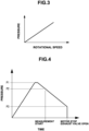
- the discharge pressure of the diaphragm pump 11 changes in correspondence with the rotational speed of the pump driving motor 2, as shown in, for example, the graph of Fig. 3 .
- the discharge pressure can be regulated to a desired value by controlling the rotational speed of the pump driving motor 2 by the pump control unit 7 of the control device 3.
- the correspondence between the rotational speed of the pump driving motor 2 and the discharge pressure of the diaphragm pump 11 is established not only when the discharge pressure is increased, but also when it is decreased.
- the discharge pressure can be regulated to a desired value by only controlling the rotational speed of the pump driving motor 2 not only when the discharge pressure is increased, but also when it is decreased.
- the pump control unit 7 of the control device 3 controls the rotational speed of the pump driving motor 2 based on a pressure in the air passage B detected by the pressure sensor 5. More specifically, the pump control unit 7 obtains a difference between a target pressure and a detected pressure, when the target pressure is higher, increases the rotational speed, and when it is lower, decreases the rotational speed, thereby adjusting the detected pressure close to the target pressure.
- the pump control unit 7 may hold in advance data representing the correspondence between the rotational speed of the pump driving motor 2 and the discharge pressure of the diaphragm pump 11, as shown in Fig. 3 , and control the rotational speed of the pump driving motor 2 based on the data without using a pressure detected by the pressure sensor 5.
- the pump control unit 7 of the control device 3 controls the rotational speed of the pump driving motor 2 so that the discharge pressure of the diaphragm pump 11 changes in a pattern suited to blood pressure measurement. That is, as shown in Fig. 4 , the pump control unit 7 increases the rotational speed of the pump driving motor 2 so that the pressure of the cuff A reaches a predetermined initial pressure P1, and then gradually decreases the rotational speed of the pump driving motor 2. When the rotational speed of the pump driving motor 2 decreases, the discharge pressure gradually lowers because air is always exhausted from the discharge fluid chamber 45 via the exhaust passage 62.
- the electronic sphygmomanometer starts blood pressure measurement when the discharge pressure lowers to P2 in a process in which the discharge pressure gradually lowers.
- the pump control unit 7 stops the pump driving motor 2. Even after the pump driving motor 2 stops, the air in the discharge fluid chamber 45 keeps exhausted into the atmosphere from the exhaust passage 62.
- the exhaust valve control unit 8 controls the exhaust valve 6 to open. When the exhaust valve 6 opens, the air in the air passage B is exhausted into the atmosphere and the cuff A contracts to an initial shape.
- the pressure in the discharge passage 54 can be regulated by changing the rotational speed of the driving mechanism 15 (driving device) of the diaphragm pump 11 without using a slow exhaust valve in the discharge passage 54 of the diaphragm pump 11. Since a slow exhaust valve is unnecessary, the manufacturing costs of the diaphragm pump and pressure regulating apparatus can be reduced. There can be provided a low-cost diaphragm pump and pressure regulating apparatus capable of regulating the pressure without using a slow exhaust valve.
- a pressure regulating apparatus according to the second embodiment of the present invention will be described in detail with reference to Figs. 5 to 10 .
- a pressure regulating apparatus 101 shown in Fig. 5 can be used as an apparatus that supplies air to, for example, a cuff A (pressurization target object) of an electronic sphygmomanometer.
- the pressure regulating apparatus 101 includes a pump driving motor 102, a control device 103 that controls the operation of the pump driving motor 102, an operation switch 104 connected to the control device 103, and a pressure sensor 105.
- the control device 103 includes a pump control unit 106.
- the pump driving motor 102 receives power from the pump control unit 106 of the control device 103 to rotate and drive a diaphragm pump 111 (to be described later).
- the diaphragm pump 111 is driven by the pump driving motor 102 to supply air to the cuff A of the electronic sphygmomanometer, details of which will be described later.
- the pressure sensor 105 detects a pressure in an air passage B (fluid passage) between the diaphragm pump 111 and the cuff A, and sends the detected pressure as a signal to the control device 103.
- the pump control unit 106 of the control device 103 controls the rotational speed of the pump driving motor 102 based on the pressure detected by the pressure sensor 105.
- the operation of the control device 103 will be described later.
- the operation switch 104 is a switch that is manually operated to switch the control device 103 between ON and OFF.
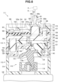
- the diaphragm pump 111 is attached to the pump driving motor 102 located at the lowermost position in Fig. 6 .
- the diaphragm pump 111 includes a driving unit 112 fixed to the pump driving motor 102, and a valve unit 113 attached to the driving unit 112.
- the driving unit 112 includes a driving unit housing 114 fixed to the pump driving motor 102, and a driving mechanism 115 (driving device) stored in the housing 114.
- the housing 114 is formed into a bottomed cylindrical shape and fixed to the pump driving motor 102 by a fixing bolt (not shown).
- the driving mechanism 115 includes a crank body 117 attached to a rotating shaft 116 of the pump driving motor 102, and a driving body 118 connected to the crank body 117.
- the driving body 118 includes a shaft portion 118a that tilts in a predetermined direction with respect to the rotating shaft 116, and a plurality of arm portions 118b projecting outward from the middle portion of the shaft portion 118a in the radial direction.
- One end of the shaft portion 118a is engaged with the crank body 117 rotatably and swingably so that the shaft portion 118a can rotate about the rotating shaft 116 together with the crank body 117.
- the other end of the shaft portion 118a is swingably supported by a diaphragm holder 121 attached to the opening portion of the housing 114.
- the arm portions 118b are provided for respective pump portions 132 of a diaphragm 131 (to be described later) and radially extend outward from the shaft portion 118a in the radial direction.
- Fig. 6 shows only one arm portion 118b, but the arm portions 118b equal in number to the pump portions 132 are provided actually.
- a through hole 122 is formed in each arm portion 118b.
- a connecting piece 133 of the diaphragm 131 is inserted in the through hole 122. The connecting piece 133 extends through the arm portion 118b and is fixed to the arm portion 118b in this state.
- the driving mechanism 115 a rotational force is applied from the rotating shaft 116 of the pump driving motor 102 to rotate the crank body 117.
- the driving body 118 swings, and each pump portion 132 of the diaphragm 131 repetitively contracts and expands. That is, the driving mechanism 115 converts the rotation of the crank body 117 into a reciprocating motion to increase/decrease the capacity of a pump chamber 134 in the pump portion 132.
- the valve unit 113 includes the diaphragm 131 connected to the driving body 118, the diaphragm holder 121 attached to the opening portion of the driving unit housing 114, a diaphragm housing 135 attached to the diaphragm holder 121 via the diaphragm 131, and a cover 137 attached to the diaphragm housing 135 via a partition 136.
- the diaphragm 131 is sandwiched between the diaphragm holder 121 and the diaphragm housing 135.
- the diaphragm holder 121, the diaphragm housing 135, the partition 136, and the cover 137 are each formed into a circular shape when viewed from the axial direction of the pump driving motor 102.
- the diaphragm holder 121 is formed into a cylindrical shape connectable to the driving unit housing 114, and includes a plurality of cylinder holes 138 in which the pump portions 132 of the diaphragm 131 (to be described later) are inserted, and a concave portion 139 that is open toward the diaphragm 131.
- the diaphragm 131 includes the cup-shaped pump portions 132 that are open toward the diaphragm housing 135, plate-shaped suction valves 141 each projecting inward from the peripheral portion of the opening portion of the corresponding pump portion 132, and a cylindrical valve element 142 inserted in the concave portion 139 of the diaphragm holder 121.
- the pump portions 132, the suction valves 141, and the cylindrical valve element 142 are provided at positions at which the diaphragm 131 is divided into a plurality of parts in the circumferential direction of the cylindrical diaphragm holder 121.
- Each pump portion 132 is inserted into the cylinder hole 138 formed in the diaphragm holder 121.
- the opening portion of the pump portion 132 is closed by the diaphragm housing 135.
- the pump chamber 134 using the corresponding pump portion 132 as part of the wall is formed between the pump portion 132 and the diaphragm housing 135.
- a piston 143 is formed on the bottom of the cup-shaped pump portion 132.
- the connecting piece 133 projects from the piston 143 in a direction opposite to the pump chamber 134.
- the connecting piece 133 is connected to the driving body 118 of the driving mechanism 115.
- the driving mechanism 115 is connected to the bottom of the pump portion 132.
- the suction valve 141 opens/closes a suction passage 144 formed in the diaphragm housing 135.
- the suction passage 144 is constituted by a first groove 145 formed in a mating surface between the diaphragm 131 and the diaphragm holder 121 in the diaphragm housing 135.
- One end of the suction passage 144 is connected to the pump chamber 134 via the suction valve 141, and the other end of the suction passage 144 is connected to a fluid inlet 146 that is open in the outer surface (outside the diaphragm pump 111) of the diaphragm housing 135. That is, the suction passage 144 makes the pump chamber 134 communicate with the fluid inlet 146 via the suction valve 141.
- the suction valve 141 opens the opening portion of one end of the suction passage 144 in a process in which the pump portion 132 of the diaphragm 131 expands to increase the capacity of the pump chamber 134, and closes the opening portion in a process in which the pump portion 132 contracts to decrease the capacity of the pump chamber 134. That is, the suction valve 141 opens/closes the suction passage 144 so that a fluid flows from the fluid inlet 146 toward the pump chamber 134 in a process in which the capacity of the pump chamber 134 increases.
- the cylindrical valve element 142 constitutes a first check valve 148 together with a column 147 of the diaphragm housing 135.
- the column 147 constitutes the valve seat of the first check valve 148.
- the cylindrical valve element 142 is formed into a cylindrical shape covering the outer peripheral surface of the column 147.
- the first check valve 148 is interposed between a second groove 149 and the concave portion 139 of the diaphragm holder 121.
- the second groove 149 is formed in a surface mating with the diaphragm 131 in the diaphragm housing 135.
- One end of the second groove 149 is open to the pump chamber 134.
- the first check valve 148 is constituted so that air flows from the second groove 149 toward the concave portion 139.
- the inside of the concave portion 139 is connected to an input-side space 153 (to be described later) via an upstream-side space 150 formed between the diaphragm holder 121 and the diaphragm 131, a first through hole 151 formed in the diaphragm 131, and a second through hole 152 formed in the diaphragm housing 135.
- the input-side space 153 is formed between the diaphragm housing 135 and the partition 136 (to be described later), and communicates with the pump chamber 134 via a continuous space from the second groove 149 to the second through hole 152. Note that the input-side space 153 communicates with each of the pump chambers 134.
- the diaphragm housing 135 is formed into a plate shape, overlaps the diaphragm 131 to cover the opening portion of each pump portion 132, and forms the pump chamber 134 together with the pump portion 132.
- the partition 136 is formed into a plate shape by an elastic member such as a rubber material including synthetic rubber.
- the partition 136 is sandwiched and held between the diaphragm housing 135 and the cover 137, and separates the diaphragm housing 135 and the cover 137.
- the above-described input-side space 153 is formed between the partition 136 and the diaphragm housing 135, and an output-side space 154 is formed between the partition 136 and the cover 137.
- the output-side space 154 is separated from the input-side space 153 by the partition 136.
- the output-side space 154 is connected to an outlet passage 162 in a discharge pipe 161 projecting from the center portion of the cover 137, a first exhaust passage 163 formed in one side portion (left side portion in Fig. 6 ) of the cover 137, and a second exhaust passage 165 that is open in a concave portion 164 formed inside the center portion of the cover 137.
- a third exhaust passage 166 is formed in the cover 137 so as to be adjacent to the output-side space 154.
- the outlet passage 162 in the discharge pipe 161 makes the inside of the concave portion 164 of the cover 137 communicate with a fluid discharge port 162a formed at the distal end of the discharge pipe 161.
- the fluid discharge port 162a is open to the outer surface (outside the diaphragm pump 111) of the discharge pipe 161.
- the discharge pipe 161 is connected to, for example, the cuff A of the electronic sphygmomanometer via an air hose constituting the air passage B.
- first exhaust passage 163 One end of the first exhaust passage 163 is connected to the output-side space 154, and the other end of the first exhaust passage 163 is connected to a first exhaust port 163a that is open to the outer surface (outside the diaphragm pump 111) of the cover 137. That is, the first exhaust passage 163 makes the first exhaust port 163a communicate with an area between the fluid discharge port 162a and a fluid outlet 191a of a discharge valve 191 (to be described later) in a discharge passage 174 (to be described later).
- the second exhaust passage 165 is connected to the concave portion 164 (output-side space 154) of the cover 137, and the other end of the second exhaust passage 165 is connected to a second exhaust port 165a that is open to the outer surface (outside the diaphragm pump 111) of the cover 137. That is, the second exhaust passage 165 makes the second exhaust port 165a communicate with an area between the fluid discharge port 162a and the fluid outlet 191a of the discharge valve 191 (to be described later) in the discharge passage 174 (to be described later).
- the second exhaust passage 165 is always open.
- the hole diameter (width) of the second exhaust port 165a is smaller than that of the first exhaust port 163a.
- the width of the second exhaust port 165a is smaller than that of the fluid discharge port 162a, and the width of the second exhaust passage 165 is smaller than that of the outlet passage 162 in the discharge pipe 161.
- One end of the third exhaust passage 166 is open to a surface mating with the partition 136 in the cover 137, and the other end of the third exhaust passage 166 is connected to a third exhaust port 166a that is open to the outer surface (outside the diaphragm pump 111) of the cover 137.
- a cylindrical valve element 171 is formed in the partition 136 and projects toward the concave portion 164 of the cover 137.
- the cylindrical valve element 171 constitutes a second check valve 173 together with a column 172 of the diaphragm housing 135.
- the second check valve 173 makes air in the input-side space 153 flow into the concave portion 164 (output-side space 154) of the cover 137.
- the column 172 constitutes the valve seat of the second check valve 173.
- the cylindrical valve element 171 is formed into a cylindrical shape covering the outer peripheral surface of the column 172.
- the projecting end of the cylindrical valve element 171 is in contact with the outer peripheral surface of the column 172 all over the circumferential direction.
- the inner diameter of the base end portion of the cylindrical valve element 171 is larger than the outer diameter of the column 172.
- the space between the base end portion of the cylindrical valve element 171 and the column 172 is part of the input-side space 153, and constitutes part of the discharge passage 174 of the diaphragm pump 111.
- the discharge passage 174 is a passage that makes the pump chamber 134 communicate with the fluid discharge port 162a of the discharge pipe 161.
- the discharge passage 174 is constituted by the second groove 149 communicating with the pump chamber 134, the space in the concave portion 139 of the diaphragm holder 121, the upstream-side space 150, the first and second through holes 151 and 152, the input-side space 153, the space in the concave portion 164 of the cover 137, the outlet passage 162 in the discharge pipe 161, and the like.
- the above-described first check valve 148 and second check valve 173 are provided in the discharge passage 174, and air flows from the pump chamber 134 toward the outlet passage 162.
- the first check valve 148 and the second check valve 173 constitute the discharge valve 191 of the diaphragm pump 111.
- the discharge valve 191 closes the discharge passage 174 in a process in which the pump portion 132 of the diaphragm 131 expands to increase the capacity of the pump chamber 134, and opens the discharge passage 174 in a process in which the pump portion 132 contracts to decrease the capacity of the pump chamber 134. That is, the discharge valve 191 opens/closes the discharge passage 174 so that a fluid flows from the pump chamber 134 toward the fluid discharge port 162a in a process in which the capacity of the pump chamber 134 decreases.
- the projecting end of the cylindrical valve element 171 and the outer peripheral surface of the column 172 constitute the fluid outlet 191a of the discharge valve 191.
- One end of the first exhaust passage 163 is connected via the output-side space 154 to an area in the discharge passage 174 between the fluid outlet 191a of the discharge valve 191 and the fluid discharge port 162a of the discharge pipe 161, and one end of the second exhaust passage 165 is also connected.
- the input-side space 153 is arranged on the upstream side from the fluid outlet 191a of the discharge valve 191.
- the pressure on the downstream side from the fluid outlet 191a of the discharge valve 191 is almost equal to the pressure in the output-side space 154, and the pressure on the upstream side from the fluid outlet 191a is almost equal to the pressure in the input-side space 153.
- a valve element 182 of a differential pressure regulating valve 181 (to be described later) and a third through hole 184 that receives a columnar projection 183 of the diaphragm housing 135 are formed in the partition 136.
- the third through hole 184 is connected to the third exhaust passage 166.
- the third exhaust passage 166 makes the third exhaust port 166a communicate with an area (input-side space 153) on the upstream side from the fluid outlet 191a of the discharge valve 191 in the discharge passage 174.
- the differential pressure regulating valve 181 is constituted by the valve element 182 and a valve seat 185 in which the first exhaust passage 163 is open.
- the valve element 182 moves by a pressure difference between the input-side space 153 and the output-side space 154 to open/close the first exhaust passage 163.
- the valve element 182 comes into contact with the diaphragm housing 135, as shown in Fig. 6 .
- valve element 182 moves apart from the diaphragm housing 135 and is seated on the valve seat 185 of the cover 137.
- the valve element 182 is seated on the valve seat 185, the first exhaust passage 163 is closed.
- the differential pressure regulating valve 181 closes the first exhaust passage 163 when the pressure on the upstream side from the fluid outlet 191a of the discharge valve 191 in the discharge passage 174 is higher than that in the first exhaust passage 163, and opens the discharge passage 174 when the pressure on the upstream side from the fluid outlet 191a of the discharge valve 191 in the discharge passage 174 is equal to or lower than that in the first exhaust passage 163.
- the inner diameter of the third through hole 184 of the partition 136 is slightly larger than the outer diameter of the columnar projection 183.
- a small gap is formed between the hole wall surface of the third through hole 184 and the peripheral surface of the columnar projection 183.
- the input-side space 153 is open to the atmosphere via the small gap between the columnar projection 183 and the third through hole 184 and the third exhaust passage 166 of the cover 137.
- the suction valve 141 opens to suck the atmosphere into the pump chamber 134 via the suction passage 144.
- the air in the pump chamber 134 is sent to the input-side space 153 via the second groove 149, the first check valve 148, the concave portion 139, the upstream-side space 150, and the first and second through holes 151 and 152.
- the capacity of the pump chamber 134 decreases to pressurize the input-side space 153 and generate a pressure difference between the input-side space 153 and the output-side space 154.
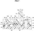
- the differential pressure regulating valve 181 operates. The operation of the differential pressure regulating valve 181 will be described in detail with reference to Figs. 7 and 8 .
- Figs. 7 and 8 are sectional views for explaining the operation of the differential pressure regulating valve.
- the same reference numerals denote the same or similar members as or to those described with reference to Fig. 6 , and a detailed description thereof will be omitted appropriately.
- the air in the input-side space 153 is exhausted into the atmosphere via the third exhaust passage 166.
- the pressure Pin in the input-side space 153 becomes equal to or lower than the pressure Pout in the output-side space 154, opening the differential pressure regulating valve 181.
- the differential pressure regulating valve 181 opens, the air in the output-side space 154 is exhausted into the atmosphere via the first exhaust passage 163.
- the air in the discharge passage 174 between the fluid outlet 191a of the discharge valve 191 and the fluid discharge port 162a is exhausted into the atmosphere via the second exhaust passage 165.
- part of air having passed through the second check valve 173 is exhausted into the atmosphere via the second exhaust passage 165.
- Part of air in the input-side space 153 is exhausted into the atmosphere via the third through hole 184 and the third exhaust passage 166.
- the discharge pressure of air discharged from the fluid discharge port 162a can be easily regulated by controlling the rotational speed of the motor 102 to adjust the balance between the discharge amount and the exhaust amount.
- the pressure in the discharge passage 174, the exhaust amount of air exhausted from the second exhaust port 165a via the second exhaust passage 165, and the exhaust amount of air exhausted from the third exhaust port 166a via the third exhaust passage 166 are uniquely determined by determining the rotational speed of the pump driving motor 102. If the rotational speed of the pump driving motor 102 changes, the pressure in the discharge passage 174 and the two exhaust amounts also change in correspondence with the change of the rotational speed. The pressure in the discharge passage 174 almost coincides with the discharge pressure of air discharged from the fluid discharge port 162a, that is, the discharge pressure of the diaphragm pump 111.
- the discharge pressure of the diaphragm pump 111 changes in correspondence with the rotational speed of the pump driving motor 102, as shown in, for example, the graph of Fig. 9 .
- the discharge pressure can be regulated to a desired value by controlling the rotational speed of the pump driving motor 102 by the pump control unit 106 of the control device 103.
- the correspondence between the rotational speed of the pump driving motor 102 and the discharge pressure of the diaphragm pump 111 is established not only when the discharge pressure is increased, but also when it is decreased.
- the discharge pressure can be regulated to a desired value by only controlling the rotational speed of the pump driving motor 102 not only when the discharge pressure is increased, but also when it is decreased.
- the pump control unit 106 of the control device 103 controls the rotational speed of the pump driving motor 102 based on a pressure in the air passage B detected by the pressure sensor 105. More specifically, the pump control unit 107 obtains a difference between a target pressure and a detected pressure, when the target pressure is higher, increases the rotational speed, and when it is lower, decreases the rotational speed, thereby adjusting the detected pressure close to the target pressure.
- the pump control unit 106 may hold in advance data representing the correspondence between the rotational speed of the pump driving motor 102 and the discharge pressure of the diaphragm pump 111, as shown in Fig. 9 , and control the rotational speed of the pump driving motor 102 based on the data without using a pressure detected by the pressure sensor 105.
- the pump control unit 106 of the control device 103 controls the rotational speed of the pump driving motor 102 so that the discharge pressure of the diaphragm pump 111 changes in a pattern suited to blood pressure measurement. That is, as shown in Fig. 10 , the pump control unit 106 increases the rotational speed of the pump driving motor 102 so that the pressure of the cuff A reaches a predetermined initial pressure P1, and then gradually decreases the rotational speed of the pump driving motor 102. When the rotational speed of the pump driving motor 102 decreases, the discharge pressure gradually lowers because air is always exhausted from the output-side space 154 via the second exhaust passage 165.
- the electronic sphygmomanometer starts blood pressure measurement when the discharge pressure lowers to a pressure P2 in a process in which the discharge pressure gradually lowers.
- the pump control unit 106 stops the pump driving motor 102.
- the differential pressure regulating valve 181 opens to exhaust the air in the output-side space 154 from the first exhaust passage 163 into the atmosphere.
- the air in the output-side space 154 is exhausted from the second exhaust passage 165 into the atmosphere, and the air in the input-side space 153 is exhausted from the third exhaust passage 166 into the atmosphere. Accordingly, the cuff A contracts to an initial shape.
- the pressure in the discharge passage 174 can be regulated by changing the rotational speed of the driving mechanism 115 (driving device) of the diaphragm pump 111 without using a slow exhaust valve in the air passage B (exhaust system of the diaphragm pump 111) between the diaphragm pump 111 and the cuff A. Since a slow exhaust valve is unnecessary, the manufacturing cost of the pressure regulating apparatus can be reduced. There can be provided a low-cost pressure regulating apparatus capable of regulating the pressure without using a slow exhaust valve in the exhaust system.
- the differential pressure regulating valve 181 When the differential pressure regulating valve 181 is opened/closed by controlling the rotational speed of the pump driving motor 102, the differential pressure regulating valve 181 may vibrate to generate a ripple of air.
- air is always exhausted from the second exhaust passage 165, the pressure is smoothened on the downstream side from the fluid outlet 191a of the discharge valve 191, and thus the generation of a ripple can be suppressed.
- the diaphragm pump 111 does not include the second exhaust passage 165, it includes the third exhaust passage 166, and the discharge pressure can be regulated by controlling the rotational speed of the pump driving motor 102 by the pump control unit 106 of the control device 103.
- the present invention is not limited to this, and can be applied to any apparatus as long as the apparatus regulates the pressure by supplying and exhausting a gas or a liquid.
Abstract
Description
- The present invention relates to a diaphragm pump capable of regulating the pressure of a discharged fluid, and a pressure regulating apparatus using the diaphragm pump.
- A pressure regulating apparatus that pressurizes a pressurization target object using air as a medium and decreases the pressure of the pressurization target object is used to supply air to, for example, the cuff of an electronic sphygmomanometer.
Japanese Patent Laid-Open No. 2015-70969 -
Japanese Patent Laid-Open No. 2018-112127 - The pressure regulating apparatus disclosed in literature 1 uses a slow exhaust valve to regulate the pressure. This increases the number of parts and the manufacturing cost.
- It is an object of the present invention to provide a diaphragm pump and pressure regulating apparatus capable of regulating the pressure without using a slow exhaust valve in an exhaust system.
- In order to achieve the object, according to the present invention, there is provided a diaphragm pump comprising a diaphragm including a cup-shaped pump portion, a pump chamber including a wall including the pump portion, a driving device connected to a bottom of the pump portion and configured to convert a rotation into a reciprocating motion and increase/decrease a capacity of the pump chamber, a fluid inlet, a fluid discharge port, and a fluid exhaust port that are open to outside of the diaphragm pump, a suction passage configured to make the pump chamber communicate with the fluid inlet, a suction valve configured to open/close the suction passage to make a fluid flow from the fluid inlet toward the pump chamber in a process in which the capacity of the pump chamber increases, a discharge passage configured to make the pump chamber communicate with the fluid discharge port, a discharge valve configured to open/close the discharge passage to make the fluid flow from the pump chamber toward the fluid discharge port in a process in which the capacity of the pump chamber decreases, and an exhaust passage configured to make the discharge passage communicate with the fluid exhaust port.
- The exhaust passage may always be open.
- The exhaust passage may be connected to an area on a downstream side of the discharge valve in the discharge passage.
- A width of the fluid exhaust port may be smaller than a width of the fluid discharge port.
- The diaphragm pump may further comprise a diaphragm housing forming the pump chamber together with the diaphragm, and a cover attached to the diaphragm housing, and the exhaust passage may include a through hole formed in the cover.
- The diaphragm pump may further comprise a diaphragm housing forming the pump chamber together with the diaphragm, and a cover attached to the diaphragm housing. The cover may include a discharge pipe. The fluid inlet, the fluid discharge port, and the fluid exhaust port may be formed in an outer surface of the cover. The suction passage may include a suction fluid chamber formed between the diaphragm housing and the cover, a first through hole formed in the diaphragm housing and configured to make the suction fluid chamber communicate with the pump chamber, and a second through hole formed in the cover and configured to make the fluid inlet communicate with the suction fluid chamber. The discharge passage may include a discharge fluid chamber formed between the diaphragm housing and the cover, a third through hole formed in the diaphragm housing and configured to make the discharge fluid chamber communicate with the pump chamber, and a hollow portion of the discharge pipe configured to make the fluid discharge port communicate with the discharge fluid chamber. The discharge passage may include a fourth through hole formed in the cover and configured to make the fluid discharge port communicate with the discharge fluid chamber.
- According to the present invention, there is provided a pressure regulating apparatus comprising the above-described diaphragm pump, a motor configured to apply a rotational force to the driving device, and a control device configured to control an operation of the motor, wherein the control device is configured to control a rotational speed of the motor and regulate a pressure of the fluid discharged from the fluid discharge port.
- The pressure regulating apparatus may further comprise a fluid passage configured to make the discharge passage communicate with a pressurization target object, and an exhaust valve configured to selectively exhaust the fluid in the fluid passage.
- The pressure regulating apparatus may further comprise a pressure sensor configured to detect a pressure in the fluid passage, and the control device may be configured to control the rotational speed based on the pressure detected by the pressure sensor.
- The control device may be configured to control the rotational speed and regulate the pressure not only when the pressure is increased, but also when the pressure is decreased.
- According to the present invention, there is provided a pressure regulating apparatus comprising a diaphragm including a cup-shaped pump portion, a pump chamber including a wall including the pump portion, a driving device connected to a bottom of the pump portion and configured to convert a rotation into a reciprocating motion and increase/decrease a capacity of the pump chamber, a motor configured to apply a rotational force to the driving device, a fluid inlet, a fluid discharge port, and a first exhaust port that are open to outside of the diaphragm pump, a suction passage configured to make the pump chamber communicate with the fluid inlet, a suction valve configured to open/close the suction passage to make a fluid flow from the fluid inlet toward the pump chamber in a process in which the capacity of the pump chamber increases, a discharge passage configured to make the pump chamber communicate with the fluid discharge port, a discharge valve configured to open/close the discharge passage to make the fluid flow from the pump chamber toward the fluid discharge port in a process in which the capacity of the pump chamber decreases, a first exhaust passage configured to make the first exhaust port communicate with an area in the discharge passage between a fluid outlet of the discharge valve and the fluid discharge port, a differential pressure regulating valve configured to close the first exhaust passage when a pressure on an upstream side from the fluid outlet of the discharge valve in the discharge passage is higher than a pressure in the first exhaust passage, and open the first exhaust passage when the pressure on the upstream side from the fluid outlet of the discharge valve in the discharge passage is not higher than the pressure in the first exhaust passage, and a control device configured to control an operation of the motor, wherein the control device is configured to control a rotational speed of the motor and regulate a pressure of the fluid discharged from the fluid discharge port.
- The pressure regulating apparatus may further comprise a second exhaust port that is open to the outside of the diaphragm pump, and a second exhaust passage configured to make the second exhaust port communicate with the area in the discharge passage between the fluid outlet of the discharge valve and the fluid discharge port.
- The second exhaust passage may always be open.
- A width of the second exhaust port may be smaller than a width of the fluid discharge port.
- The pressure regulating apparatus may further comprise a third exhaust port that is open to the outside of the diaphragm pump, and a third exhaust passage configured to make the third exhaust port communicate with an area on the upstream side from the fluid outlet of the discharge valve in the discharge passage.
- The pressure regulating apparatus may further comprise a fluid passage configured to make the discharge passage communicate with a pressurization target object, and a pressure sensor configured to detect a pressure in the fluid passage, and the control device may be configured to control the rotational speed based on the pressure detected by the pressure sensor.
- The control device may be configured to control the rotational speed and regulate the pressure not only when the pressure is increased, but also when the pressure is decreased.
- The discharge passage may include an input-side space arranged on the upstream side from the fluid outlet of the discharge valve, and an output-side space may be interposed between the first exhaust passage, and the area in the discharge passage between the fluid outlet of the discharge valve and the fluid discharge port. The input-side space may be separated from the output-side space by a partition including the differential pressure regulating valve.
- The diaphragm pump may further comprise a diaphragm housing forming the pump chamber together with the pump portion of the diaphragm, a cover attached to the diaphragm housing, and a partition sandwiched between the diaphragm housing and the cover. An input-side space is formed between the diaphragm housing and the partition, and an output-side space is formed between the cover and the partition. The input-side space is part of the discharge passage and is arranged on the upstream side from the fluid outlet of the discharge valve. The output-side space is interposed between the first exhaust passage, and the area in the discharge passage between the fluid outlet of the discharge valve and the fluid discharge port. The partition includes the differential pressure regulating valve.
- The fluid inlet, the fluid discharge port, the first exhaust port, the suction passage, the discharge passage, and the first exhaust passage may be formed in the cover. The second exhaust port and the second exhaust passage may be formed in the cover. The third exhaust port and the third exhaust passage may be formed in the cover. The partition may include a through hole configured to make the input-side space communicate with the third exhaust passage. The third exhaust passage/the through hole may always be open.
-
-
Fig. 1 is a block diagram of a pressure regulating apparatus according to the first embodiment of the present invention; -
Fig. 2 is a sectional view of a diaphragm pump; -
Fig. 3 is a graph showing the relationship between the rotational speed of a motor and the discharge pressure of the diaphragm pump; -
Fig. 4 is a graph showing a temporal change of the discharge pressure; -
Fig. 5 is a block diagram of a pressure regulating apparatus according to the second embodiment of the present invention; -
Fig. 6 is a sectional view of a diaphragm pump; -
Fig. 7 is a sectional view for explaining the operation of a differential pressure regulating valve; -
Fig. 8 is a sectional view for explaining the operation of the differential pressure regulating valve; -
Fig. 9 is a graph showing the relationship between the rotational speed of a motor and the discharge pressure of the diaphragm pump; and -
Fig. 10 is a graph showing a temporal change of the discharge pressure. - A diaphragm pump and a pressure regulating apparatus according to the first embodiment of the present invention will be described in detail with reference to
Figs. 1 to 4 . - A pressure regulating apparatus 1 shown in
Fig. 1 can be used as an apparatus that supplies air to, for example, a cuff A (pressurization target object) of an electronic sphygmomanometer. The pressure regulating apparatus 1 includes apump driving motor 2, acontrol device 3 that controls the operation of thepump driving motor 2, anoperation switch 4 connected to thecontrol device 3, apressure sensor 5, and anexhaust valve 6. Thecontrol device 3 includes apump control unit 7 and an exhaustvalve control unit 8. - The
pump driving motor 2 receives power from thepump control unit 7 of thecontrol device 3 to rotate and drive a diaphragm pump 11 (to be described later). Thediaphragm pump 11 is driven by thepump driving motor 2 to supply air to the cuff A of the electronic sphygmomanometer, details of which will be described later. Thepressure sensor 5 detects a pressure in an air passage B (fluid passage) between thediaphragm pump 11 and the cuff A, and sends the detected pressure as a signal to thecontrol device 3. Theexhaust valve 6 is formed from an electromagnetic valve and selectively exhausts air in the air passage B into the atmosphere. The operation of theexhaust valve 6 is controlled by the exhaustvalve control unit 8 of thecontrol device 3. - The
pump control unit 7 of thecontrol device 3 controls the rotational speed of thepump driving motor 2 based on the pressure detected by thepressure sensor 5. The exhaustvalve control unit 8 of thecontrol device 3 controls theexhaust valve 6 to open theexhaust valve 6 when exhausting a residual pressure in the cuff A, and close it in other times. The operation of thecontrol device 3 will be described later. Theoperation switch 4 is a switch that is manually operated to switch thecontrol device 3 between ON and OFF. - As shown in
Fig. 2 , thediaphragm pump 11 is attached to thepump driving motor 2 located at the lowermost position inFig. 2 . Thediaphragm pump 11 includes a drivingunit 12 fixed to thepump driving motor 2, and avalve unit 13 attached to the drivingunit 12. - The driving
unit 12 includes a drivingunit housing 14 fixed to thepump driving motor 2, and a driving mechanism 15 (driving device) stored in thehousing 14. Thehousing 14 is formed into a bottomed cylindrical shape and fixed to thepump driving motor 2 by a fixing bolt (not shown). Thedriving mechanism 15 includes acrank body 17 attached to arotating shaft 16 of thepump driving motor 2, and a drivingbody 19 connected to the crankbody 17 via a drivingshaft 18. - The driving
shaft 18 is attached to the crankbody 17 in a state in which it tilts in a predetermined direction with respect to therotating shaft 16. The drivingbody 19 includes acolumnar shaft portion 20 and a plurality ofarm portions 21 projecting outward from theshaft portion 20 in the radial direction. Theshaft portion 20 has a center hole in which the drivingshaft 18 is inserted, and is rotatably supported by the drivingshaft 18. Thearm portions 21 are provided forrespective pump portions 32 of a diaphragm 31 (to be described later) and radially extend outward from theshaft portion 20 in the radial direction. A throughhole 21a is formed in eacharm portion 21. A connectingpiece 33 of thediaphragm 31 is inserted in the throughhole 21a. The connectingpiece 33 extends through thearm portion 21 and is fixed to thearm portion 21 in this state. - According to the
driving mechanism 15, a rotational force is applied from the rotatingshaft 16 of thepump driving motor 2 to rotate thecrank body 17 and the drivingshaft 18. The drivingbody 19 swings, and eachpump portion 32 of thediaphragm 31 repetitively contracts and expands. That is, thedriving mechanism 15 converts the rotation of thecrank body 17 into a reciprocating motion to increase/decrease the capacity of apump chamber 34 in thepump portion 32. - The
valve unit 13 includes thediaphragm 31 connected to the drivingbody 19, adiaphragm holder 35 attached to the opening portion of the drivingunit housing 14, adiaphragm housing 36 attached to thediaphragm holder 35 via thediaphragm 31, and acover 37 attached to thediaphragm housing 36. Thediaphragm 31 is sandwiched between thediaphragm holder 35 and thediaphragm housing 36. Thediaphragm holder 35, thediaphragm housing 36, and thecover 37 are each formed into a circular shape when viewed from the axial direction of thepump driving motor 2. - The
diaphragm holder 35 is formed into a cylindrical shape connectable to the drivingunit housing 14, and includes a plurality of cylinder holes 38 in which thepump portions 32 of the diaphragm 31 (to be described later) are inserted. - The
diaphragm 31 includes the plurality of cup-shapedpump portions 32 that are open toward thediaphragm housing 36. Thepump portions 32 are provided at positions at which thediaphragm 31 is divided into a plurality of parts in the circumferential direction of thecylindrical diaphragm holder 35. Eachpump portion 32 is inserted into thecylinder hole 38 formed in thediaphragm holder 35. The opening portion of thepump portion 32 is closed by thediaphragm housing 36. Thepump chamber 34 using thepump portion 32 as part of the wall is formed between thepump portion 32 and thediaphragm housing 36. - A
piston 39 is provided on the bottom of the cup-shapedpump portion 32. The connectingpiece 33 projects from thepiston 39 in a direction opposite to thepump chamber 34. As described above, the connectingpiece 33 is connected to the drivingbody 19 of thedriving mechanism 15. Thedriving mechanism 15 is connected to the bottom of thepump portion 32. When the drivingbody 19 of thedriving mechanism 15 swings, the bottom (piston 39) of thepump portion 32 comes into contact with or moves apart from thediaphragm housing 36 to increase/decrease the capacity of thepump chamber 34. - The
diaphragm housing 36 is formed into a disk shape. An annularsuction fluid chamber 43 is formed at an outer peripheral portion between thediaphragm housing 36 and thecover 37. Adischarge fluid chamber 45 is formed on the center side between thediaphragm housing 36 and thecover 37. Thesuction fluid chamber 43 and thedischarge fluid chamber 45 are separated by acylindrical wall 44. - A plurality of first through
holes 46 are formed on the outer peripheral side of thediaphragm housing 36 and provided for therespective pump chambers 34. The first throughholes 46 make thesuction fluid chamber 43 communicate with thepump chambers 34. Afluid inlet 48 is formed in the outer surface of thecover 37 and open to the outside of thediaphragm pump 11. A second throughhole 47 is further formed in thecover 37 and makes thefluid inlet 48 communicate with thesuction fluid chamber 43. Thesuction fluid chamber 43 communicates with the atmosphere via the second throughhole 47. In this embodiment, the first throughholes 46 provided for therespective pump chambers 34, thesuction fluid chamber 43, the second throughhole 47, and the like form asuction passage 49 that makes thepump chambers 34 communicate with thefluid inlet 48 outside the pump. That is, one end of thesuction passage 49 is connected to thepump chamber 34, and the other end of thesuction passage 49 is connected to thefluid inlet 48. - The
diaphragm housing 36 supports on its outer peripheral side a plurality ofsuction valves 41 provided for therespective pump chambers 34. Eachsuction valve 41 opens/closes thesuction passage 49 and is formed into a predetermined shape by a rubber material. Thesuction valve 41 includes ashaft portion 41a that extends through thediaphragm housing 36 and is fixed to thediaphragm housing 36, and avalve element 41b formed into a disk shape at the distal end of theshaft portion 41a. Thevalve element 41b is arranged at a position where it overlaps the opening portion of the first throughhole 46 in thepump chamber 34. Thevalve element 41b opens the opening portion of the first throughhole 46 in a process in which thepump portion 32 of thediaphragm 31 expands to increase the capacity of thepump chamber 34, and closes the opening portion of the first throughhole 46 in a process in which thepump portion 32 contracts to decrease the capacity of thepump chamber 34. That is, thesuction valve 41 opens/closes thesuction passage 49 so that a fluid flows from thefluid inlet 48 toward thepump chamber 34 in a process in which the capacity of thepump chamber 34 increases. - A plurality of third through
holes 51 are formed on the center side of thediaphragm housing 36 and provided for therespective pump chambers 34. The third throughholes 51 make thedischarge fluid chambers 45 communicate withpump chambers 34. Adischarge pipe 52 projects from the center portion of thecover 37. Afluid discharge port 53 is formed at the distal end (outer surface of the cover 37) of thedischarge pipe 52 and open to the outside of thediaphragm pump 11. Ahollow portion 52a of thedischarge pipe 52 extends from thefluid discharge port 53 to thedischarge fluid chamber 45. Thedischarge fluid chamber 45 therefore communicates with the atmosphere via thedischarge pipe 52. In this embodiment, the third throughholes 51 provided for therespective pump chambers 34, thedischarge fluid chamber 45, thehollow portion 52a of thedischarge pipe 52, and the like constitute adischarge passage 54 that makes thepump chambers 34 communicate with thefluid discharge port 53. That is, one end of thedischarge passage 54 is connected to thepump chamber 34, and the other end of thedischarge passage 54 is connected to thefluid discharge port 53 outside the pump. - The
discharge pipe 52 is connected to, for example, the cuff A of the electronic sphygmomanometer via an air hose constituting the air passage B. The above-describedpressure sensor 5 is arranged in the air passage B that makes thedischarge passage 54 communicate with the cuff A, and detects a pressure in the air passage B. The above-describedexhaust valve 6 is also provided in the air passage B. - The
diaphragm housing 36 supports adischarge valve 42 at the center portion. Thedischarge valve 42 is formed from a rubber material and includes avalve element 42a in tight contact with a wall surface of thediaphragm housing 36 on thedischarge fluid chamber 45 side. Thevalve element 42a is arranged at a position where it overlaps the opening portions of the third through holes 51. Thevalve element 42a closes the opening portion of the third throughhole 51 in a process in which thepump portion 32 of thediaphragm 31 expands to increase the capacity of thepump chamber 34, and opens the opening portion of the third throughhole 51 in a process in which thepump portion 32 contracts to decrease the capacity of thepump chamber 34. That is, thedischarge valve 42 opens/closes thedischarge passage 54 so that a fluid flows from thepump chamber 34 toward thefluid discharge port 53 in a process in which the capacity of thepump chamber 34 decreases. - A
fluid exhaust port 63 is formed in the outer surface of thecover 37 at a portion where thecover 37 covers thedischarge fluid chamber 45, and is open to the outside of thediaphragm pump 11. A fourth throughhole 61 is further formed at this portion and makes thefluid exhaust port 63 communicate with thedischarge fluid chamber 45. The fourth throughhole 61 is always open. Thedischarge fluid chamber 45 is part of thedischarge passage 54. In this embodiment, the fourth throughhole 61 constitutes anexhaust passage 62 that makes thedischarge passage 54 communicate with thefluid exhaust port 63. That is, one end of theexhaust passage 62 is connected to the discharge passage 54 (more specifically, connected to an area on the downstream side of thedischarge valve 42 in the discharge passage 54), and the other end of theexhaust passage 62 is connected to thefluid exhaust port 63 outside the pump. Note that a plurality offluid exhaust ports 63 and a plurality of fourth through holes 61 (exhaust passages 62) may be formed in thecover 37. - The width of the
fluid exhaust port 63 is smaller than that of thefluid discharge port 53, and the width of the fourth throughhole 61 is smaller than that of thehollow portion 52a of thedischarge pipe 52. In other words, the width of theexhaust passage 62 is smaller than that of the narrowest portion of thedischarge passage 54. - In the
diaphragm pump 11 having this structure, when thepump portion 32 of thediaphragm 31 expands to increase the capacity of thepump chamber 34, thesuction valve 41 opens to suck the atmosphere into thepump chamber 34 via thesuction passage 49. In contrast, when thepump portion 32 of thediaphragm 31 contracts to decrease the capacity of thepump chamber 34, thedischarge valve 42 opens to supply air in thepump chamber 34 to thedischarge fluid chamber 45 via the third throughhole 51. Most of the air flowing into thedischarge fluid chamber 45 is discharged from thefluid discharge port 53 via thehollow portion 52a (discharge passage 54) of thedischarge pipe 52 and sent to the cuff A via the air hose (air passage B). - Part of the air flowing into the
discharge fluid chamber 45 is exhausted into the atmosphere via theexhaust passage 62. The discharge pressure of air discharged from thefluid discharge port 53 can be easily regulated by controlling the rotational speed of themotor 2 to adjust the balance between the discharge amount and the exhaust amount. - When the cuff A is connected to the
discharge pipe 52 via the air hose, the pressure in thedischarge fluid chamber 45 and the exhaust amount of air exhausted from thefluid exhaust port 63 via theexhaust passage 62 are uniquely determined by determining the rotational speed of thepump driving motor 2. If the rotational speed of thepump driving motor 2 changes, the pressure in thedischarge fluid chamber 45 and the exhaust amount also change in correspondence with the change of the rotational speed. The pressure in thedischarge fluid chamber 45 almost coincides with the discharge pressure of air discharged from thefluid discharge port 53, that is, the discharge pressure of thediaphragm pump 11. The discharge pressure of thediaphragm pump 11 changes in correspondence with the rotational speed of thepump driving motor 2, as shown in, for example, the graph ofFig. 3 . The discharge pressure can be regulated to a desired value by controlling the rotational speed of thepump driving motor 2 by thepump control unit 7 of thecontrol device 3. - The correspondence between the rotational speed of the
pump driving motor 2 and the discharge pressure of thediaphragm pump 11 is established not only when the discharge pressure is increased, but also when it is decreased. According to this embodiment, the discharge pressure can be regulated to a desired value by only controlling the rotational speed of thepump driving motor 2 not only when the discharge pressure is increased, but also when it is decreased. - In this embodiment, the
pump control unit 7 of thecontrol device 3 controls the rotational speed of thepump driving motor 2 based on a pressure in the air passage B detected by thepressure sensor 5. More specifically, thepump control unit 7 obtains a difference between a target pressure and a detected pressure, when the target pressure is higher, increases the rotational speed, and when it is lower, decreases the rotational speed, thereby adjusting the detected pressure close to the target pressure. Note that thepump control unit 7 may hold in advance data representing the correspondence between the rotational speed of thepump driving motor 2 and the discharge pressure of thediaphragm pump 11, as shown inFig. 3 , and control the rotational speed of thepump driving motor 2 based on the data without using a pressure detected by thepressure sensor 5. - When the pressure regulating apparatus 1 according to this embodiment is mounted in an electronic sphygmomanometer, the
pump control unit 7 of thecontrol device 3 controls the rotational speed of thepump driving motor 2 so that the discharge pressure of thediaphragm pump 11 changes in a pattern suited to blood pressure measurement. That is, as shown inFig. 4 , thepump control unit 7 increases the rotational speed of thepump driving motor 2 so that the pressure of the cuff A reaches a predetermined initial pressure P1, and then gradually decreases the rotational speed of thepump driving motor 2. When the rotational speed of thepump driving motor 2 decreases, the discharge pressure gradually lowers because air is always exhausted from thedischarge fluid chamber 45 via theexhaust passage 62. - The electronic sphygmomanometer starts blood pressure measurement when the discharge pressure lowers to P2 in a process in which the discharge pressure gradually lowers. When the discharge pressure reaches P3 after the end of blood pressure measurement, the
pump control unit 7 stops thepump driving motor 2. Even after thepump driving motor 2 stops, the air in thedischarge fluid chamber 45 keeps exhausted into the atmosphere from theexhaust passage 62. When the discharge pressure reaches P3, the exhaustvalve control unit 8 controls theexhaust valve 6 to open. When theexhaust valve 6 opens, the air in the air passage B is exhausted into the atmosphere and the cuff A contracts to an initial shape. - According to the first embodiment, the pressure in the
discharge passage 54 can be regulated by changing the rotational speed of the driving mechanism 15 (driving device) of thediaphragm pump 11 without using a slow exhaust valve in thedischarge passage 54 of thediaphragm pump 11. Since a slow exhaust valve is unnecessary, the manufacturing costs of the diaphragm pump and pressure regulating apparatus can be reduced. There can be provided a low-cost diaphragm pump and pressure regulating apparatus capable of regulating the pressure without using a slow exhaust valve. - A pressure regulating apparatus according to the second embodiment of the present invention will be described in detail with reference to
Figs. 5 to 10 . - A
pressure regulating apparatus 101 shown inFig. 5 can be used as an apparatus that supplies air to, for example, a cuff A (pressurization target object) of an electronic sphygmomanometer. Thepressure regulating apparatus 101 includes apump driving motor 102, acontrol device 103 that controls the operation of thepump driving motor 102, anoperation switch 104 connected to thecontrol device 103, and apressure sensor 105. Thecontrol device 103 includes apump control unit 106. - The
pump driving motor 102 receives power from thepump control unit 106 of thecontrol device 103 to rotate and drive a diaphragm pump 111 (to be described later). Thediaphragm pump 111 is driven by thepump driving motor 102 to supply air to the cuff A of the electronic sphygmomanometer, details of which will be described later. Thepressure sensor 105 detects a pressure in an air passage B (fluid passage) between thediaphragm pump 111 and the cuff A, and sends the detected pressure as a signal to thecontrol device 103. - The
pump control unit 106 of thecontrol device 103 controls the rotational speed of thepump driving motor 102 based on the pressure detected by thepressure sensor 105. The operation of thecontrol device 103 will be described later. Theoperation switch 104 is a switch that is manually operated to switch thecontrol device 103 between ON and OFF. - As shown in
Fig. 6 , thediaphragm pump 111 is attached to thepump driving motor 102 located at the lowermost position inFig. 6 . Thediaphragm pump 111 includes adriving unit 112 fixed to thepump driving motor 102, and avalve unit 113 attached to thedriving unit 112. - The driving
unit 112 includes a drivingunit housing 114 fixed to thepump driving motor 102, and a driving mechanism 115 (driving device) stored in thehousing 114. Thehousing 114 is formed into a bottomed cylindrical shape and fixed to thepump driving motor 102 by a fixing bolt (not shown). Thedriving mechanism 115 includes a crankbody 117 attached to arotating shaft 116 of thepump driving motor 102, and a drivingbody 118 connected to the crankbody 117. - The driving
body 118 includes ashaft portion 118a that tilts in a predetermined direction with respect to therotating shaft 116, and a plurality ofarm portions 118b projecting outward from the middle portion of theshaft portion 118a in the radial direction. One end of theshaft portion 118a is engaged with thecrank body 117 rotatably and swingably so that theshaft portion 118a can rotate about therotating shaft 116 together with thecrank body 117. The other end of theshaft portion 118a is swingably supported by adiaphragm holder 121 attached to the opening portion of thehousing 114. - The
arm portions 118b are provided forrespective pump portions 132 of a diaphragm 131 (to be described later) and radially extend outward from theshaft portion 118a in the radial direction.Fig. 6 shows only onearm portion 118b, but thearm portions 118b equal in number to thepump portions 132 are provided actually. A throughhole 122 is formed in eacharm portion 118b. A connectingpiece 133 of thediaphragm 131 is inserted in the throughhole 122. The connectingpiece 133 extends through thearm portion 118b and is fixed to thearm portion 118b in this state. - According to the
driving mechanism 115, a rotational force is applied from therotating shaft 116 of thepump driving motor 102 to rotate the crankbody 117. The drivingbody 118 swings, and eachpump portion 132 of thediaphragm 131 repetitively contracts and expands. That is, thedriving mechanism 115 converts the rotation of thecrank body 117 into a reciprocating motion to increase/decrease the capacity of apump chamber 134 in thepump portion 132. - The
valve unit 113 includes thediaphragm 131 connected to the drivingbody 118, thediaphragm holder 121 attached to the opening portion of the drivingunit housing 114, adiaphragm housing 135 attached to thediaphragm holder 121 via thediaphragm 131, and acover 137 attached to thediaphragm housing 135 via apartition 136. Thediaphragm 131 is sandwiched between thediaphragm holder 121 and thediaphragm housing 135. Thediaphragm holder 121, thediaphragm housing 135, thepartition 136, and thecover 137 are each formed into a circular shape when viewed from the axial direction of thepump driving motor 102. - The
diaphragm holder 121 is formed into a cylindrical shape connectable to the drivingunit housing 114, and includes a plurality of cylinder holes 138 in which thepump portions 132 of the diaphragm 131 (to be described later) are inserted, and aconcave portion 139 that is open toward thediaphragm 131. - The
diaphragm 131 includes the cup-shapedpump portions 132 that are open toward thediaphragm housing 135, plate-shapedsuction valves 141 each projecting inward from the peripheral portion of the opening portion of thecorresponding pump portion 132, and acylindrical valve element 142 inserted in theconcave portion 139 of thediaphragm holder 121. Thepump portions 132, thesuction valves 141, and thecylindrical valve element 142 are provided at positions at which thediaphragm 131 is divided into a plurality of parts in the circumferential direction of thecylindrical diaphragm holder 121. - Each
pump portion 132 is inserted into thecylinder hole 138 formed in thediaphragm holder 121. The opening portion of thepump portion 132 is closed by thediaphragm housing 135. Thepump chamber 134 using thecorresponding pump portion 132 as part of the wall is formed between thepump portion 132 and thediaphragm housing 135. Apiston 143 is formed on the bottom of the cup-shapedpump portion 132. The connectingpiece 133 projects from thepiston 143 in a direction opposite to thepump chamber 134. As described above, the connectingpiece 133 is connected to the drivingbody 118 of thedriving mechanism 115. Thedriving mechanism 115 is connected to the bottom of thepump portion 132. When the drivingbody 118 of thedriving mechanism 115 swings, the bottom (piston 143) of thepump portion 132 comes into contact with or moves apart from thediaphragm housing 135 to increase/decrease the capacity of thepump chamber 134. - The
suction valve 141 opens/closes asuction passage 144 formed in thediaphragm housing 135. Thesuction passage 144 is constituted by afirst groove 145 formed in a mating surface between thediaphragm 131 and thediaphragm holder 121 in thediaphragm housing 135. One end of thesuction passage 144 is connected to thepump chamber 134 via thesuction valve 141, and the other end of thesuction passage 144 is connected to afluid inlet 146 that is open in the outer surface (outside the diaphragm pump 111) of thediaphragm housing 135. That is, thesuction passage 144 makes thepump chamber 134 communicate with thefluid inlet 146 via thesuction valve 141. - The
suction valve 141 opens the opening portion of one end of thesuction passage 144 in a process in which thepump portion 132 of thediaphragm 131 expands to increase the capacity of thepump chamber 134, and closes the opening portion in a process in which thepump portion 132 contracts to decrease the capacity of thepump chamber 134. That is, thesuction valve 141 opens/closes thesuction passage 144 so that a fluid flows from thefluid inlet 146 toward thepump chamber 134 in a process in which the capacity of thepump chamber 134 increases. - The
cylindrical valve element 142 constitutes afirst check valve 148 together with acolumn 147 of thediaphragm housing 135. Thecolumn 147 constitutes the valve seat of thefirst check valve 148. Thecylindrical valve element 142 is formed into a cylindrical shape covering the outer peripheral surface of thecolumn 147. Thefirst check valve 148 is interposed between asecond groove 149 and theconcave portion 139 of thediaphragm holder 121. Thesecond groove 149 is formed in a surface mating with thediaphragm 131 in thediaphragm housing 135. One end of thesecond groove 149 is open to thepump chamber 134. Thefirst check valve 148 is constituted so that air flows from thesecond groove 149 toward theconcave portion 139. - The inside of the
concave portion 139 is connected to an input-side space 153 (to be described later) via an upstream-side space 150 formed between thediaphragm holder 121 and thediaphragm 131, a first throughhole 151 formed in thediaphragm 131, and a second throughhole 152 formed in thediaphragm housing 135. The input-side space 153 is formed between thediaphragm housing 135 and the partition 136 (to be described later), and communicates with thepump chamber 134 via a continuous space from thesecond groove 149 to the second throughhole 152. Note that the input-side space 153 communicates with each of thepump chambers 134. - The
diaphragm housing 135 is formed into a plate shape, overlaps thediaphragm 131 to cover the opening portion of eachpump portion 132, and forms thepump chamber 134 together with thepump portion 132. - The
partition 136 is formed into a plate shape by an elastic member such as a rubber material including synthetic rubber. Thepartition 136 is sandwiched and held between thediaphragm housing 135 and thecover 137, and separates thediaphragm housing 135 and thecover 137. The above-described input-side space 153 is formed between thepartition 136 and thediaphragm housing 135, and an output-side space 154 is formed between thepartition 136 and thecover 137. - The output-
side space 154 is separated from the input-side space 153 by thepartition 136. The output-side space 154 is connected to anoutlet passage 162 in adischarge pipe 161 projecting from the center portion of thecover 137, afirst exhaust passage 163 formed in one side portion (left side portion inFig. 6 ) of thecover 137, and asecond exhaust passage 165 that is open in aconcave portion 164 formed inside the center portion of thecover 137. Athird exhaust passage 166 is formed in thecover 137 so as to be adjacent to the output-side space 154. - The
outlet passage 162 in thedischarge pipe 161 makes the inside of theconcave portion 164 of thecover 137 communicate with afluid discharge port 162a formed at the distal end of thedischarge pipe 161. Thefluid discharge port 162a is open to the outer surface (outside the diaphragm pump 111) of thedischarge pipe 161. Thedischarge pipe 161 is connected to, for example, the cuff A of the electronic sphygmomanometer via an air hose constituting the air passage B. - One end of the
first exhaust passage 163 is connected to the output-side space 154, and the other end of thefirst exhaust passage 163 is connected to afirst exhaust port 163a that is open to the outer surface (outside the diaphragm pump 111) of thecover 137. That is, thefirst exhaust passage 163 makes thefirst exhaust port 163a communicate with an area between thefluid discharge port 162a and afluid outlet 191a of a discharge valve 191 (to be described later) in a discharge passage 174 (to be described later). - One end of the
second exhaust passage 165 is connected to the concave portion 164 (output-side space 154) of thecover 137, and the other end of thesecond exhaust passage 165 is connected to asecond exhaust port 165a that is open to the outer surface (outside the diaphragm pump 111) of thecover 137. That is, thesecond exhaust passage 165 makes thesecond exhaust port 165a communicate with an area between thefluid discharge port 162a and thefluid outlet 191a of the discharge valve 191 (to be described later) in the discharge passage 174 (to be described later). Thesecond exhaust passage 165 is always open. The hole diameter (width) of thesecond exhaust port 165a is smaller than that of thefirst exhaust port 163a. The width of thesecond exhaust port 165a is smaller than that of thefluid discharge port 162a, and the width of thesecond exhaust passage 165 is smaller than that of theoutlet passage 162 in thedischarge pipe 161. - One end of the
third exhaust passage 166 is open to a surface mating with thepartition 136 in thecover 137, and the other end of thethird exhaust passage 166 is connected to athird exhaust port 166a that is open to the outer surface (outside the diaphragm pump 111) of thecover 137. - A
cylindrical valve element 171 is formed in thepartition 136 and projects toward theconcave portion 164 of thecover 137. Thecylindrical valve element 171 constitutes asecond check valve 173 together with acolumn 172 of thediaphragm housing 135. Thesecond check valve 173 makes air in the input-side space 153 flow into the concave portion 164 (output-side space 154) of thecover 137. Thecolumn 172 constitutes the valve seat of thesecond check valve 173. Thecylindrical valve element 171 is formed into a cylindrical shape covering the outer peripheral surface of thecolumn 172. The projecting end of thecylindrical valve element 171 is in contact with the outer peripheral surface of thecolumn 172 all over the circumferential direction. The inner diameter of the base end portion of thecylindrical valve element 171 is larger than the outer diameter of thecolumn 172. The space between the base end portion of thecylindrical valve element 171 and thecolumn 172 is part of the input-side space 153, and constitutes part of thedischarge passage 174 of thediaphragm pump 111. - The
discharge passage 174 is a passage that makes thepump chamber 134 communicate with thefluid discharge port 162a of thedischarge pipe 161. In this embodiment, thedischarge passage 174 is constituted by thesecond groove 149 communicating with thepump chamber 134, the space in theconcave portion 139 of thediaphragm holder 121, the upstream-side space 150, the first and second throughholes side space 153, the space in theconcave portion 164 of thecover 137, theoutlet passage 162 in thedischarge pipe 161, and the like. The above-describedfirst check valve 148 andsecond check valve 173 are provided in thedischarge passage 174, and air flows from thepump chamber 134 toward theoutlet passage 162. - In this embodiment, the
first check valve 148 and thesecond check valve 173 constitute thedischarge valve 191 of thediaphragm pump 111. Thedischarge valve 191 closes thedischarge passage 174 in a process in which thepump portion 132 of thediaphragm 131 expands to increase the capacity of thepump chamber 134, and opens thedischarge passage 174 in a process in which thepump portion 132 contracts to decrease the capacity of thepump chamber 134. That is, thedischarge valve 191 opens/closes thedischarge passage 174 so that a fluid flows from thepump chamber 134 toward thefluid discharge port 162a in a process in which the capacity of thepump chamber 134 decreases. - The projecting end of the
cylindrical valve element 171 and the outer peripheral surface of thecolumn 172 constitute thefluid outlet 191a of thedischarge valve 191. One end of thefirst exhaust passage 163 is connected via the output-side space 154 to an area in thedischarge passage 174 between thefluid outlet 191a of thedischarge valve 191 and thefluid discharge port 162a of thedischarge pipe 161, and one end of thesecond exhaust passage 165 is also connected. The input-side space 153 is arranged on the upstream side from thefluid outlet 191a of thedischarge valve 191. The pressure on the downstream side from thefluid outlet 191a of thedischarge valve 191 is almost equal to the pressure in the output-side space 154, and the pressure on the upstream side from thefluid outlet 191a is almost equal to the pressure in the input-side space 153. - A
valve element 182 of a differential pressure regulating valve 181 (to be described later) and a third throughhole 184 that receives acolumnar projection 183 of thediaphragm housing 135 are formed in thepartition 136. The third throughhole 184 is connected to thethird exhaust passage 166. Thethird exhaust passage 166 makes thethird exhaust port 166a communicate with an area (input-side space 153) on the upstream side from thefluid outlet 191a of thedischarge valve 191 in thedischarge passage 174. - The differential
pressure regulating valve 181 is constituted by thevalve element 182 and avalve seat 185 in which thefirst exhaust passage 163 is open. Thevalve element 182 moves by a pressure difference between the input-side space 153 and the output-side space 154 to open/close thefirst exhaust passage 163. When the pressure in the input-side space 153 is equal to or lower than that in the output-side space 154, thevalve element 182 comes into contact with thediaphragm housing 135, as shown inFig. 6 . When the pressure in the input-side space 153 becomes higher than that in the output-side space 154 and the pressure difference exceeds a predetermined value, thevalve element 182 moves apart from thediaphragm housing 135 and is seated on thevalve seat 185 of thecover 137. When thevalve element 182 is seated on thevalve seat 185, thefirst exhaust passage 163 is closed. That is, the differentialpressure regulating valve 181 closes thefirst exhaust passage 163 when the pressure on the upstream side from thefluid outlet 191a of thedischarge valve 191 in thedischarge passage 174 is higher than that in thefirst exhaust passage 163, and opens thedischarge passage 174 when the pressure on the upstream side from thefluid outlet 191a of thedischarge valve 191 in thedischarge passage 174 is equal to or lower than that in thefirst exhaust passage 163. - The inner diameter of the third through
hole 184 of thepartition 136 is slightly larger than the outer diameter of thecolumnar projection 183. When thecolumnar projection 183 is inserted in the third throughhole 184, a small gap is formed between the hole wall surface of the third throughhole 184 and the peripheral surface of thecolumnar projection 183. The input-side space 153 is open to the atmosphere via the small gap between thecolumnar projection 183 and the third throughhole 184 and thethird exhaust passage 166 of thecover 137. - In the
diaphragm pump 111 having this structure, when thepump portion 132 of thediaphragm 131 expands to increase the capacity of thepump chamber 134, thesuction valve 141 opens to suck the atmosphere into thepump chamber 134 via thesuction passage 144. - In contrast, when the
pump portion 132 of thediaphragm 131 contracts to decrease the capacity of thepump chamber 134, the air in thepump chamber 134 is sent to the input-side space 153 via thesecond groove 149, thefirst check valve 148, theconcave portion 139, the upstream-side space 150, and the first and second throughholes pump chamber 134 decreases to pressurize the input-side space 153 and generate a pressure difference between the input-side space 153 and the output-side space 154. When the pressure difference exceeds a predetermined value, the differentialpressure regulating valve 181 operates. The operation of the differentialpressure regulating valve 181 will be described in detail with reference toFigs. 7 and8 . -
Figs. 7 and8 are sectional views for explaining the operation of the differential pressure regulating valve. InFigs. 7 and8 , the same reference numerals denote the same or similar members as or to those described with reference toFig. 6 , and a detailed description thereof will be omitted appropriately. - As shown in
Fig. 7 , when a pressure Pin in the input-side space 153 becomes higher than a pressure Pout in the output-side space 154 by a predetermined pressure difference, thevalve element 182 of the differentialpressure regulating valve 181 is seated on thevalve seat 185 and closes thefirst exhaust passage 163. As indicated by arrows inFig. 7 , most of air having passed through thesecond check valve 173 is discharged from thefluid discharge port 162a, and part of the air having passed through thesecond check valve 173 is exhausted from thesecond exhaust port 165a into the atmosphere. When an air hose is connected to thedischarge pipe 161, the air discharged from thefluid discharge port 162a is sent to the cuff A via the air hose (air passage B). At this time, part of the air in the input-side space 153 is exhausted into the atmosphere via the third throughhole 184 and thethird exhaust passage 166. - Even if the
motor 102 stops, the air in the input-side space 153 is exhausted into the atmosphere via thethird exhaust passage 166. As a result, the pressure Pin in the input-side space 153 becomes equal to or lower than the pressure Pout in the output-side space 154, opening the differentialpressure regulating valve 181. When the differentialpressure regulating valve 181 opens, the air in the output-side space 154 is exhausted into the atmosphere via thefirst exhaust passage 163. At this time, the air in thedischarge passage 174 between thefluid outlet 191a of thedischarge valve 191 and thefluid discharge port 162a is exhausted into the atmosphere via thesecond exhaust passage 165. - In the
diaphragm pump 111 according to this embodiment, part of air having passed through thesecond check valve 173 is exhausted into the atmosphere via thesecond exhaust passage 165. Part of air in the input-side space 153 is exhausted into the atmosphere via the third throughhole 184 and thethird exhaust passage 166. The discharge pressure of air discharged from thefluid discharge port 162a can be easily regulated by controlling the rotational speed of themotor 102 to adjust the balance between the discharge amount and the exhaust amount. - When the cuff A is connected to the
discharge pipe 161 via the air hose, the pressure in thedischarge passage 174, the exhaust amount of air exhausted from thesecond exhaust port 165a via thesecond exhaust passage 165, and the exhaust amount of air exhausted from thethird exhaust port 166a via thethird exhaust passage 166 are uniquely determined by determining the rotational speed of thepump driving motor 102. If the rotational speed of thepump driving motor 102 changes, the pressure in thedischarge passage 174 and the two exhaust amounts also change in correspondence with the change of the rotational speed. The pressure in thedischarge passage 174 almost coincides with the discharge pressure of air discharged from thefluid discharge port 162a, that is, the discharge pressure of thediaphragm pump 111. The discharge pressure of thediaphragm pump 111 changes in correspondence with the rotational speed of thepump driving motor 102, as shown in, for example, the graph ofFig. 9 . The discharge pressure can be regulated to a desired value by controlling the rotational speed of thepump driving motor 102 by thepump control unit 106 of thecontrol device 103. - The correspondence between the rotational speed of the
pump driving motor 102 and the discharge pressure of thediaphragm pump 111 is established not only when the discharge pressure is increased, but also when it is decreased. According to this embodiment, the discharge pressure can be regulated to a desired value by only controlling the rotational speed of thepump driving motor 102 not only when the discharge pressure is increased, but also when it is decreased. - In this embodiment, the
pump control unit 106 of thecontrol device 103 controls the rotational speed of thepump driving motor 102 based on a pressure in the air passage B detected by thepressure sensor 105. More specifically, the pump control unit 107 obtains a difference between a target pressure and a detected pressure, when the target pressure is higher, increases the rotational speed, and when it is lower, decreases the rotational speed, thereby adjusting the detected pressure close to the target pressure. Note that thepump control unit 106 may hold in advance data representing the correspondence between the rotational speed of thepump driving motor 102 and the discharge pressure of thediaphragm pump 111, as shown inFig. 9 , and control the rotational speed of thepump driving motor 102 based on the data without using a pressure detected by thepressure sensor 105. - When the
pressure regulating apparatus 101 according to this embodiment is mounted in an electronic sphygmomanometer, thepump control unit 106 of thecontrol device 103 controls the rotational speed of thepump driving motor 102 so that the discharge pressure of thediaphragm pump 111 changes in a pattern suited to blood pressure measurement. That is, as shown inFig. 10 , thepump control unit 106 increases the rotational speed of thepump driving motor 102 so that the pressure of the cuff A reaches a predetermined initial pressure P1, and then gradually decreases the rotational speed of thepump driving motor 102. When the rotational speed of thepump driving motor 102 decreases, the discharge pressure gradually lowers because air is always exhausted from the output-side space 154 via thesecond exhaust passage 165. - The electronic sphygmomanometer starts blood pressure measurement when the discharge pressure lowers to a pressure P2 in a process in which the discharge pressure gradually lowers. When the discharge pressure reaches a pressure P3 from the pressure P2 after the end of blood pressure measurement, the
pump control unit 106 stops thepump driving motor 102. When thepump driving motor 102 stops, the differentialpressure regulating valve 181 opens to exhaust the air in the output-side space 154 from thefirst exhaust passage 163 into the atmosphere. Also, the air in the output-side space 154 is exhausted from thesecond exhaust passage 165 into the atmosphere, and the air in the input-side space 153 is exhausted from thethird exhaust passage 166 into the atmosphere. Accordingly, the cuff A contracts to an initial shape. - According to the second embodiment, the pressure in the
discharge passage 174 can be regulated by changing the rotational speed of the driving mechanism 115 (driving device) of thediaphragm pump 111 without using a slow exhaust valve in the air passage B (exhaust system of the diaphragm pump 111) between thediaphragm pump 111 and the cuff A. Since a slow exhaust valve is unnecessary, the manufacturing cost of the pressure regulating apparatus can be reduced. There can be provided a low-cost pressure regulating apparatus capable of regulating the pressure without using a slow exhaust valve in the exhaust system. - When the differential
pressure regulating valve 181 is opened/closed by controlling the rotational speed of thepump driving motor 102, the differentialpressure regulating valve 181 may vibrate to generate a ripple of air. However, in thediaphragm pump 111 according to the second embodiment, air is always exhausted from thesecond exhaust passage 165, the pressure is smoothened on the downstream side from thefluid outlet 191a of thedischarge valve 191, and thus the generation of a ripple can be suppressed. Even if thediaphragm pump 111 does not include thesecond exhaust passage 165, it includes thethird exhaust passage 166, and the discharge pressure can be regulated by controlling the rotational speed of thepump driving motor 102 by thepump control unit 106 of thecontrol device 103. - The above-described embodiments have described an example in which the present invention is applied to an electronic sphygmomanometer. However, the present invention is not limited to this, and can be applied to any apparatus as long as the apparatus regulates the pressure by supplying and exhausting a gas or a liquid.
Claims (6)
- A pressure regulating apparatus (101) comprising:a diaphragm (131) including a cup-shaped pump portion (132);a pump chamber (134) including a wall including the pump portion;a driving device (115) connected to a bottom of the pump portion and configured to convert a rotation into a reciprocating motion and increase/decrease a capacity of the pump chamber (134);a motor (102) configured to apply a rotational force to the driving device;a fluid inlet (146), a fluid discharge port (162a), and a first exhaust port (163a) that are open to outside of the diaphragm pump;a suction passage (144) configured to make the pump chamber communicate with the fluid inlet;a suction valve (141) configured to open/close the suction passage to make a fluid flow from the fluid inlet toward the pump chamber in a process in which the capacity of the pump chamber increases;a discharge passage (174) configured to make the pump chamber communicate with the fluid discharge port;a discharge valve (191) configured to open/close the discharge passage to make the fluid flow from the pump chamber toward the fluid discharge port in a process in which the capacity of the pump chamber decreases;a first exhaust passage (163) configured to make the first exhaust port communicate with an area in the discharge passage between a fluid outlet (191a) of the discharge valve and the fluid discharge port;a differential pressure regulating valve (181) configured to close the first exhaust passage when a pressure on an upstream side from the fluid outlet of the discharge valve in the discharge passage is higher than a pressure in the first exhaust passage, and open the first exhaust passage when the pressure on the upstream side from the fluid outlet of the discharge valve in the discharge passage is not higher than the pressure in the first exhaust passage; anda control device (103) configured to control an operation of the motor, wherein the control device is configured to control a rotational speed of the motor and regulate a pressure of the fluid discharged from the fluid discharge port,characterized in that the pressure regulating apparatus further comprises:a third exhaust port (166a) that is open to the outside of the diaphragm pump; anda third exhaust passage (166) configured to make the third exhaust port communicate with an area on the upstream side from the fluid outlet of the discharge valve in the discharge passage.
- The apparatus according to claim 1, further comprising:a second exhaust port (165a) that is open to the outside of the diaphragm pump; anda second exhaust passage (165) configured to make the second exhaust port communicate with the area in the discharge passage between the fluid outlet of the discharge valve and the fluid discharge port.
- The apparatus according to claim 2, wherein the second exhaust passage is always open.
- The apparatus according to claim 2 or 3, wherein a width of the second exhaust port is smaller than a width of the fluid discharge port.
- The apparatus according to any one of claims 1 to 4, further comprising:a fluid passage (B) configured to make the discharge passage communicate with a pressurization target object (A); anda pressure sensor (105) configured to detect a pressure in the fluid passage,wherein the control device is configured to control the rotational speed based on the pressure detected by the pressure sensor.
- The apparatus according to any one of claims 1 to 5, wherein the control device is configured to control the rotational speed and regulate the pressure not only when the pressure is increased, but also when the pressure is decreased.
Applications Claiming Priority (3)
| Application Number | Priority Date | Filing Date | Title |
|---|---|---|---|
| JP2020043930A JP2021143646A (en) | 2020-03-13 | 2020-03-13 | Diaphragm pump and pressure adjustment device |
| JP2020043931A JP2021143647A (en) | 2020-03-13 | 2020-03-13 | Pressure adjustment device |
| EP21156792.0A EP3879102B1 (en) | 2020-03-13 | 2021-02-12 | Diaphragm pump and pressure regulating apparatus |
Related Parent Applications (1)
| Application Number | Title | Priority Date | Filing Date |
|---|---|---|---|
| EP21156792.0A Division EP3879102B1 (en) | 2020-03-13 | 2021-02-12 | Diaphragm pump and pressure regulating apparatus |
Publications (2)
| Publication Number | Publication Date |
|---|---|
| EP4296513A2 true EP4296513A2 (en) | 2023-12-27 |
| EP4296513A3 EP4296513A3 (en) | 2024-03-06 |
Family
ID=74595129
Family Applications (2)
| Application Number | Title | Priority Date | Filing Date |
|---|---|---|---|
| EP23209763.4A Pending EP4296513A3 (en) | 2020-03-13 | 2021-02-12 | Diaphragm pump and pressure regulating apparatus |
| EP21156792.0A Active EP3879102B1 (en) | 2020-03-13 | 2021-02-12 | Diaphragm pump and pressure regulating apparatus |
Family Applications After (1)
| Application Number | Title | Priority Date | Filing Date |
|---|---|---|---|
| EP21156792.0A Active EP3879102B1 (en) | 2020-03-13 | 2021-02-12 | Diaphragm pump and pressure regulating apparatus |
Country Status (3)
| Country | Link |
|---|---|
| US (1) | US20210285436A1 (en) |
| EP (2) | EP4296513A3 (en) |
| CN (1) | CN113389716B (en) |
Families Citing this family (2)
| Publication number | Priority date | Publication date | Assignee | Title |
|---|---|---|---|---|
| JP2023163366A (en) * | 2022-04-28 | 2023-11-10 | マブチモーターオーケン株式会社 | Diaphragm pump |
| WO2023240916A1 (en) * | 2022-06-14 | 2023-12-21 | 佛山市顺德区美的洗涤电器制造有限公司 | Diaphragm pump and dish washing machine |
Citations (2)
| Publication number | Priority date | Publication date | Assignee | Title |
|---|---|---|---|---|
| JP2015070969A (en) | 2013-10-03 | 2015-04-16 | シチズンホールディングス株式会社 | Sphygmomanometer |
| JP2018112127A (en) | 2017-01-12 | 2018-07-19 | 応研精工株式会社 | Diaphragm pump |
Family Cites Families (12)
| Publication number | Priority date | Publication date | Assignee | Title |
|---|---|---|---|---|
| US4178918A (en) * | 1977-09-15 | 1979-12-18 | Cornwell Lionel B | Automatic blood pressure measuring and recording system |
| US4690171A (en) * | 1986-06-05 | 1987-09-01 | Johnston Charles F | Valve assembly for a sphygmomanometer |
| US5517999A (en) * | 1994-05-26 | 1996-05-21 | Siemens Medical Systems, Inc. | Automatic blood pressure monitor with a dual-speed control circuit for the DC inflation pump motor |
| US7296594B1 (en) * | 2005-03-22 | 2007-11-20 | Hydro-Gear Limited Partnership | Combination check valve and neutral valve assembly for use in a hydraulic component |
| US8974203B2 (en) * | 2007-04-03 | 2015-03-10 | Parker-Hannifin Corporation | Hydraulic pump end cover |
| JP5353268B2 (en) * | 2009-01-28 | 2013-11-27 | オムロンヘルスケア株式会社 | Diaphragm pump and blood pressure monitor |
| JP5775703B2 (en) * | 2011-02-21 | 2015-09-09 | 応研精工株式会社 | Diaphragm pump |
| JP5731576B2 (en) * | 2013-06-06 | 2015-06-10 | 応研精工株式会社 | Quick drain valve structure and diaphragm pump |
| JP5735690B1 (en) * | 2014-08-15 | 2015-06-17 | 応研精工株式会社 | Quick drain valve integrated diaphragm pump |
| JP6564644B2 (en) * | 2015-08-06 | 2019-08-21 | 応研精工株式会社 | Quick exhaust valve unit and diaphragm pump |
| CN108019341A (en) * | 2017-12-04 | 2018-05-11 | 苏州市海崴生物科技有限公司 | A kind of basic model quaternary diaphragm pump |
| JP7216367B2 (en) * | 2018-11-30 | 2023-02-01 | 応研精工株式会社 | Diaphragm pump |
-
2021
- 2021-02-12 EP EP23209763.4A patent/EP4296513A3/en active Pending
- 2021-02-12 EP EP21156792.0A patent/EP3879102B1/en active Active
- 2021-02-25 US US17/184,670 patent/US20210285436A1/en active Pending
- 2021-03-11 CN CN202110266651.5A patent/CN113389716B/en active Active
Patent Citations (2)
| Publication number | Priority date | Publication date | Assignee | Title |
|---|---|---|---|---|
| JP2015070969A (en) | 2013-10-03 | 2015-04-16 | シチズンホールディングス株式会社 | Sphygmomanometer |
| JP2018112127A (en) | 2017-01-12 | 2018-07-19 | 応研精工株式会社 | Diaphragm pump |
Also Published As
| Publication number | Publication date |
|---|---|
| CN113389716A (en) | 2021-09-14 |
| EP3879102A1 (en) | 2021-09-15 |
| EP4296513A3 (en) | 2024-03-06 |
| EP3879102B1 (en) | 2023-12-06 |
| US20210285436A1 (en) | 2021-09-16 |
| CN113389716B (en) | 2023-01-06 |
Similar Documents
| Publication | Publication Date | Title |
|---|---|---|
| EP3879102B1 (en) | Diaphragm pump and pressure regulating apparatus | |
| EP3006738B1 (en) | Rapid-discharge-valve structural body and diaphragm pump | |
| CN100535488C (en) | Vacuum regulating valve | |
| KR101718822B1 (en) | Diaphragm Pump Integrally Incuding Quick Discharge Valve Unit | |
| JP3806859B2 (en) | Diaphragm pump | |
| US20170356439A1 (en) | Variable Capacity Compressor | |
| JP4130566B2 (en) | Capacity control valve for variable capacity compressor | |
| KR20170120023A (en) | Control valve for variable displacement compressor | |
| JP4888803B2 (en) | Compressor | |
| JP4521484B2 (en) | Control valve for variable capacity compressor | |
| JP2009103116A (en) | Control valve for variable displacement compressor | |
| JP4389226B2 (en) | Milking machine | |
| US11225960B2 (en) | Diaphragm pump | |
| WO2002101237A1 (en) | Variable displacement compressor | |
| WO2008013162A1 (en) | Compressor | |
| JP2021143647A (en) | Pressure adjustment device | |
| US7367785B2 (en) | Reduced icing valves and gas-driven motor and reciprocating pump incorporating same | |
| JP3763087B2 (en) | Diaphragm pump | |
| JP2021143646A (en) | Diaphragm pump and pressure adjustment device | |
| US20090238698A1 (en) | Reciprocal Compressor | |
| JP4572272B2 (en) | Control valve for variable capacity compressor | |
| JP7399950B2 (en) | capacity control valve | |
| JP4474697B2 (en) | Control valve | |
| JP2009036026A (en) | Control valve for variable displacement compressor | |
| JPH0223828Y2 (en) |
Legal Events
| Date | Code | Title | Description |
|---|---|---|---|
| PUAI | Public reference made under article 153(3) epc to a published international application that has entered the european phase |
Free format text: ORIGINAL CODE: 0009012 |
|
| STAA | Information on the status of an ep patent application or granted ep patent |
Free format text: STATUS: THE APPLICATION HAS BEEN PUBLISHED |
|
| AC | Divisional application: reference to earlier application |
Ref document number: 3879102 Country of ref document: EP Kind code of ref document: P |
|
| AK | Designated contracting states |
Kind code of ref document: A2 Designated state(s): AL AT BE BG CH CY CZ DE DK EE ES FI FR GB GR HR HU IE IS IT LI LT LU LV MC MK MT NL NO PL PT RO RS SE SI SK SM TR |
|
| REG | Reference to a national code |
Ref country code: DE Ref legal event code: R079 Free format text: PREVIOUS MAIN CLASS: F04B0045040000 Ipc: F04B0043000000 |
|
| PUAL | Search report despatched |
Free format text: ORIGINAL CODE: 0009013 |
|
| AK | Designated contracting states |
Kind code of ref document: A3 Designated state(s): AL AT BE BG CH CY CZ DE DK EE ES FI FR GB GR HR HU IE IS IT LI LT LU LV MC MK MT NL NO PL PT RO RS SE SI SK SM TR |
|
| RIC1 | Information provided on ipc code assigned before grant |
Ipc: F04B 45/04 20060101ALI20240129BHEP Ipc: F04B 43/02 20060101ALI20240129BHEP Ipc: F04B 43/00 20060101AFI20240129BHEP |