EP4296499A1 - Evaporative emissions canister with integrated port in interface - Google Patents
Evaporative emissions canister with integrated port in interface Download PDFInfo
- Publication number
- EP4296499A1 EP4296499A1 EP23177747.5A EP23177747A EP4296499A1 EP 4296499 A1 EP4296499 A1 EP 4296499A1 EP 23177747 A EP23177747 A EP 23177747A EP 4296499 A1 EP4296499 A1 EP 4296499A1
- Authority
- EP
- European Patent Office
- Prior art keywords
- accessory component
- evaporative emissions
- canister
- port
- mounting bracket
- Prior art date
- Legal status (The legal status is an assumption and is not a legal conclusion. Google has not performed a legal analysis and makes no representation as to the accuracy of the status listed.)
- Pending
Links
- 239000000446 fuel Substances 0.000 claims abstract description 33
- 239000003463 adsorbent Substances 0.000 claims abstract description 9
- 238000000034 method Methods 0.000 claims abstract description 8
- 239000012530 fluid Substances 0.000 claims abstract description 5
- 238000004891 communication Methods 0.000 claims abstract description 4
- 238000010079 rubber tapping Methods 0.000 claims description 5
- 238000010276 construction Methods 0.000 claims description 3
- 238000007789 sealing Methods 0.000 claims description 3
- OKTJSMMVPCPJKN-UHFFFAOYSA-N Carbon Chemical compound [C] OKTJSMMVPCPJKN-UHFFFAOYSA-N 0.000 description 7
- 239000002828 fuel tank Substances 0.000 description 6
- 238000010926 purge Methods 0.000 description 5
- 238000002485 combustion reaction Methods 0.000 description 4
- 230000008901 benefit Effects 0.000 description 2
- 238000003915 air pollution Methods 0.000 description 1
- 229910052799 carbon Inorganic materials 0.000 description 1
- 230000000295 complement effect Effects 0.000 description 1
- 150000001875 compounds Chemical class 0.000 description 1
- 230000008878 coupling Effects 0.000 description 1
- 238000010168 coupling process Methods 0.000 description 1
- 238000005859 coupling reaction Methods 0.000 description 1
- 238000003795 desorption Methods 0.000 description 1
- 230000006870 function Effects 0.000 description 1
- 239000003502 gasoline Substances 0.000 description 1
- 229930195733 hydrocarbon Natural products 0.000 description 1
- 150000002430 hydrocarbons Chemical class 0.000 description 1
- 239000007788 liquid Substances 0.000 description 1
- 239000000463 material Substances 0.000 description 1
- 239000000203 mixture Substances 0.000 description 1
Images
Classifications
-
- F—MECHANICAL ENGINEERING; LIGHTING; HEATING; WEAPONS; BLASTING
- F02—COMBUSTION ENGINES; HOT-GAS OR COMBUSTION-PRODUCT ENGINE PLANTS
- F02M—SUPPLYING COMBUSTION ENGINES IN GENERAL WITH COMBUSTIBLE MIXTURES OR CONSTITUENTS THEREOF
- F02M25/00—Engine-pertinent apparatus for adding non-fuel substances or small quantities of secondary fuel to combustion-air, main fuel or fuel-air mixture
- F02M25/08—Engine-pertinent apparatus for adding non-fuel substances or small quantities of secondary fuel to combustion-air, main fuel or fuel-air mixture adding fuel vapours drawn from engine fuel reservoir
- F02M25/0854—Details of the absorption canister
-
- F—MECHANICAL ENGINEERING; LIGHTING; HEATING; WEAPONS; BLASTING
- F02—COMBUSTION ENGINES; HOT-GAS OR COMBUSTION-PRODUCT ENGINE PLANTS
- F02M—SUPPLYING COMBUSTION ENGINES IN GENERAL WITH COMBUSTIBLE MIXTURES OR CONSTITUENTS THEREOF
- F02M25/00—Engine-pertinent apparatus for adding non-fuel substances or small quantities of secondary fuel to combustion-air, main fuel or fuel-air mixture
- F02M25/08—Engine-pertinent apparatus for adding non-fuel substances or small quantities of secondary fuel to combustion-air, main fuel or fuel-air mixture adding fuel vapours drawn from engine fuel reservoir
- F02M25/0836—Arrangement of valves controlling the admission of fuel vapour to an engine, e.g. valve being disposed between fuel tank or absorption canister and intake manifold
-
- F—MECHANICAL ENGINEERING; LIGHTING; HEATING; WEAPONS; BLASTING
- F02—COMBUSTION ENGINES; HOT-GAS OR COMBUSTION-PRODUCT ENGINE PLANTS
- F02M—SUPPLYING COMBUSTION ENGINES IN GENERAL WITH COMBUSTIBLE MIXTURES OR CONSTITUENTS THEREOF
- F02M25/00—Engine-pertinent apparatus for adding non-fuel substances or small quantities of secondary fuel to combustion-air, main fuel or fuel-air mixture
- F02M25/08—Engine-pertinent apparatus for adding non-fuel substances or small quantities of secondary fuel to combustion-air, main fuel or fuel-air mixture adding fuel vapours drawn from engine fuel reservoir
- F02M25/0872—Details of the fuel vapour pipes or conduits
-
- F—MECHANICAL ENGINEERING; LIGHTING; HEATING; WEAPONS; BLASTING
- F02—COMBUSTION ENGINES; HOT-GAS OR COMBUSTION-PRODUCT ENGINE PLANTS
- F02M—SUPPLYING COMBUSTION ENGINES IN GENERAL WITH COMBUSTIBLE MIXTURES OR CONSTITUENTS THEREOF
- F02M25/00—Engine-pertinent apparatus for adding non-fuel substances or small quantities of secondary fuel to combustion-air, main fuel or fuel-air mixture
- F02M25/08—Engine-pertinent apparatus for adding non-fuel substances or small quantities of secondary fuel to combustion-air, main fuel or fuel-air mixture adding fuel vapours drawn from engine fuel reservoir
- F02M25/089—Layout of the fuel vapour installation
Definitions
- the disclosure generally relates to evaporative emissions canisters and, more specifically, to interfaces between evaporative emissions canisters and accessory components.
- a typical evaporative emissions canister includes a casing inside of which a gas passage is formed and filled with activated carbon as a fuel vapor adsorbent. Charge and purge ports for fuel vapor are communicated with one end of the gas passage, while an atmospheric port (vent port) for fuel vapor is communicated with the other end of the gas passage, thus allowing for charging of the canister.
- fuel vapor generated from the fuel in the fuel tank is introduced through the charge port into the canister and adsorbed by the adsorbent.
- atmospheric air is introduced through the atmospheric vent port to purge the fuel vapor in the canister by desorbing fuel vapor that was adsorbed in the adsorbent.
- the flow of air carries the purged fuel vapor to an intake system of the engine through the purge port so that the fuel vapor can be combusted within the engine, thus accomplishing a purging of the canister.
- the carbon adsorbent is regenerated and a fuel vapor adsorbing performance of the canister is revived, thereby allowing the adsorbent to repeatedly adsorb fuel vapor during periods of non-use of the engine.
- One or more of the ports of the casing may be connected to a valve or other accessory component by a hose or other similar conduit including connector fittings on each end.
- the conduit may be a pre-formed, multi-layer hose including a quick connector fitting at each end, with one of the quick connectors being connected to one of the ports in the casing and the other quick connector being connected to a port of the accessory component.
- the use of quick connectors and an intermediate hose add to the cost and space requirements of the assembly, and introduce potential leak interfaces at each of the quick connections.
- An evaporative emissions canister including a body defining an internal volume therein.
- the canister body includes a port for receiving an accessory component.
- the port is in fluid communication with the internal volume.
- a mounting bracket extends outwardly from the canister body.
- the accessory component is receivable within the port, and the accessory component is fastenable to the mounting bracket to secure the accessory component to the body.
- a sleeve seal is disposed in the port, and the accessory component is mateable with the sleeve seal.
- the sleeve seal is tubular in shape, and a male port of the accessory component is insertable into the sleeve seal.
- the mounting bracket and the body are monolithic in construction.
- the mounting bracket and the body are formed of a single molded piece.
- the mounting bracket is adjacent to the port.
- the port of the body is a female port
- the accessory component includes a male port that is receivable in the female port of the body.
- the accessory component is attached to the mounting bracket with at least one fastener.
- the mounting bracket includes a first arm and a second arm, and each of the first arm and the second arm is separately attachable to the accessory component.
- the accessory component is attachable to an end of each of the first arm and the second arm.
- a fuel system assembly including the evaporative emissions canister is also provided.
- An accessory component is received in the port of the evaporative emissions canister.
- the evaporative emissions canister is attached to the mounting bracket with at least one fastener.
- the mounting bracket of the canister body supports the accessory component, and the accessory component is secured to the canister body, thereby eliminating a hose and connector fittings between the canister body and the accessory component.
- a sleeve seal is disposed in the port.
- the sleeve seal provides a sealing engagement between the accessory component and the evaporative emissions canister.
- the accessory component is an auxiliary valve.
- the accessory component includes a housing having at least one flange, and the at least one flange is connected to the mounting bracket by the at least one fastener.
- the at least one fastener comprises a self-tapping screw.
- a method of connecting an accessory component to the evaporative emissions canister includes providing the evaporative emissions canister. The method further includes inserting a male port of the accessory component into the port of the evaporative emissions canister. The method also includes fastening the accessory component to the mounting bracket of the evaporative emissions canister.
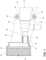
- Figure 1 is a side view of an evaporative emissions canister in accordance with some embodiments of the disclosure, the evaporative emissions canister attaching and supporting an accessory component thereto.
- an evaporative emissions canister is provided.
- the evaporative emissions canister 10 is illustrated and generally designated as a fuel vapor storage canister for a fuel tank of a vehicle fuel system that pumps liquid fuel, by way of non-limiting example gasoline fuel, from the fuel tank (not shown) to an internal combustion engine (not shown) that powers an automotive vehicle.
- the evaporative emissions canister 10 traps fuel vapors that arise in the fuel tank during periods of non-use of the internal combustion engine due to, for example, daily variations in ambient temperatures.
- the evaporative emissions canister 10 exhibits an improved, more compact, and less costly interface with accessory components.
- Figure 1 generally depicts the evaporative emissions canister 10 and an accessory component 12 such as an auxiliary fuel system valve or other component used in a vehicle fuel system and having a male port.
- the canister 10 includes a body 14 such as a casing, housing, or similar that defines an internal volume 16 inside of the body 14 and that houses the internal components of the canister.
- the internal volume 16 includes a bed 18 of at least one volume of adsorbent material such as an activated carbon or similar that adsorbs evaporative emissions such as fuel vapor to prevent these vapors from escaping to the atmosphere.
- adsorbent material such as an activated carbon or similar that adsorbs evaporative emissions such as fuel vapor to prevent these vapors from escaping to the atmosphere.
- Adsorbed fuel vapors may also be purged from the internal volume 16 of the evaporative emissions canister and directed to an air intake of an internal combustion engine to which the evaporative emissions canister is connected.
- the internal structure, internal components, and adsorb/desorb function of the evaporative emissions canister 10 may be that of any evaporative emissions canister known in the art.
- the body 14 of the canister 10 includes at least one port 20 that is in fluid communication with the internal volume 16 and that provides an inlet and/or outlet for fluid flow into and/or out of the body 14.
- the port 20 is adapted to receive the accessory component 12.
- the port 20 is a female port such as a female SAE port in which a sleeve seal 22 is disposed.
- the port 20 and sleeve seal 22 provide an interface for a male port 24 of the accessory component 12 such as a male SAE port.
- the male port 24 is inserted into and received in the female port 20 and corresponding sleeve seal 22, and the sleeve seal 22 provides a sealing engagement between the accessory component 12 and the evaporative emissions canister 10.
- the evaporative emissions canister 10 further includes a mounting bracket 26 that extends outwardly from the body 14 in the proximity of and adjacent to the port 20.
- the mounting bracket 26 may extend to the side of the body 14 in the same direction that the port 20 faces.
- the body 14 and the mounting bracket 26 may be monolithic in construction and may be formed, for example, as a single molded piece.
- the mounting bracket 26 may include first and second cantilevered arms 28, 30 that each terminate at a free end. The first arm 28 may be spaced from the second arm 30, and the first arm 28 may diverge from the second arm 30 in a direction from the body 14 towards the free ends.
- the first arm 28 may have the same shape as the second arm 30, or as shown in Figure 1 , the arms 28, 30 may differ from each other in shape, such as the first arm 28 generally being a triangular or trapezoidal shaped flange and the second arm 30 being a generally linear, rectangular shaped link bar.
- the first arm 28 and the second arm 30 are separately attachable to the accessory component 12.
- the accessory component 12 is attached to the terminal end of each of the first arm 28 and the second arm 30 with a fastener such as a self-tapping screw, a rivet, a nut and bolt, or similar.
- the accessory component 12 may include a housing 32 from which a pair of flanges 34 extend, and one of the flanges 34 is connected to the terminal end of the first arm 28 with a self-tapping screw 36 while the other one of the flanges 34 is connected to the terminal end of the second arm 30 with another self-tapping screw 36.
- the accessory component 12 may be attached and secured to the evaporative emissions canister 10 by providing the accessory component 12 and mounting bracket 26 with integrally molded, complementary locking features that interlock when assembled.
- the body 14 including the mounting bracket 26 thereby supports the accessory component 12 and secures the accessory component 12 thereto, with the male port 24 of the accessory component 12 securely inserted and sealed in the female port 20 of the evaporative emissions canister 10, without the need for quick connect couplings and/or hose conduits between the male port 24 and female port 20. Instead, the accessory component 12 is essentially directly connected to the evaporative emissions canister 10.
- mounting bracket 26 of the canister body 14 and the accessory component 12 are shown by specific example in Figure 1 .
- mounting bracket 26 may have a different shape, geometry and/or configuration so as to be connectable to other accessory components (e.g. other valves) having a different shape, geometry and/or configuration than shown.
- the disclosed canister body and associated mounting bracket can be applied, for example, to any other fuel vapor canister accessories that have a male SAE port or that would otherwise require a hose assembly to connect the accessory to the canister.
- any ranges and subranges relied upon in describing various embodiments of the present invention independently and collectively fall within the scope of the appended claims, and are understood to describe and contemplate all ranges including whole and/or fractional values therein, even if such values are not expressly written herein.
- One of skill in the art readily recognizes that the enumerated ranges and subranges sufficiently describe and enable various embodiments of the present invention, and such ranges and subranges may be further delineated into relevant halves, thirds, quarters, fifths, and so on.
- a range "of from 0.1 to 0.9" may be further delineated into a lower third, i.e., from 0.1 to 0.3, a middle third, i.e., from 0.4 to 0.6, and an upper third, i.e., from 0.7 to 0.9, which individually and collectively are within the scope of the appended claims, and may be relied upon individually and/or collectively and provide adequate support for specific embodiments within the scope of the appended claims.
- a range such as "at least,” “greater than,” “less than,” “no more than,” and the like, it is to be understood that such language includes subranges and/or an upper or lower limit.
- a range of "at least 10" inherently includes a subrange of from at least 10 to 35, a subrange of from at least 10 to 25, a subrange of from 25 to 35, and so on, and each subrange may be relied upon individually and/or collectively and provides adequate support for specific embodiments within the scope of the appended claims.
- an individual number within a disclosed range may be relied upon and provides adequate support for specific embodiments within the scope of the appended claims.
- a range "of from 1 to 9" includes various individual integers, such as 3, as well as individual numbers including a decimal point (or fraction), such as 4.1, which may be relied upon and provide adequate support for specific embodiments within the scope of the appended claims.
Abstract
An evaporative emissions canister (10) is provided. The evaporative emissions canister includes a body (14) defining an internal volume (16) therein for receiving one or more volumes of adsorbent (18). The canister body (14) includes a port (20) for receiving an accessory component (12). The port (20) is in fluid communication with the internal volume (16). A sleeve seal (22) is disposed in the port (20). A mounting bracket (26) extends outwardly from the canister body (14). The canister body supports the accessory component (12), and the accessory component is secured to the canister body (14), thereby eliminating a hose and connector fittings between the canister body and the accessory component. A fuel system assembly including the evaporative emissions canister is also provided. A method of connecting an accessory component to an evaporative emissions canister is further provided.
Description
- This application claims the benefit of
U.S. Provisional Application No. 63/350,268, filed June 8, 2022 - The disclosure generally relates to evaporative emissions canisters and, more specifically, to interfaces between evaporative emissions canisters and accessory components.
- Evaporative loss of fuel vapor generated within fuel tanks of the fuel systems of motor vehicles powered by internal combustion engines is a potential contributor to atmospheric air pollution by hydrocarbons. Canister systems that employ adsorbents such as activated carbon to adsorb the fuel vapor emitted from the fuel systems are used to limit such evaporative emissions from the fuel tanks of gasoline-fueled automotive vehicles. A typical evaporative emissions canister includes a casing inside of which a gas passage is formed and filled with activated carbon as a fuel vapor adsorbent. Charge and purge ports for fuel vapor are communicated with one end of the gas passage, while an atmospheric port (vent port) for fuel vapor is communicated with the other end of the gas passage, thus allowing for charging of the canister. During stoppage of the vehicle (e.g., when parked), fuel vapor generated from the fuel in the fuel tank is introduced through the charge port into the canister and adsorbed by the adsorbent. During operation of the engine, atmospheric air is introduced through the atmospheric vent port to purge the fuel vapor in the canister by desorbing fuel vapor that was adsorbed in the adsorbent. The flow of air carries the purged fuel vapor to an intake system of the engine through the purge port so that the fuel vapor can be combusted within the engine, thus accomplishing a purging of the canister. By the desorption of fuel vapor during purging, the carbon adsorbent is regenerated and a fuel vapor adsorbing performance of the canister is revived, thereby allowing the adsorbent to repeatedly adsorb fuel vapor during periods of non-use of the engine.
- One or more of the ports of the casing may be connected to a valve or other accessory component by a hose or other similar conduit including connector fittings on each end. For example, the conduit may be a pre-formed, multi-layer hose including a quick connector fitting at each end, with one of the quick connectors being connected to one of the ports in the casing and the other quick connector being connected to a port of the accessory component. However, the use of quick connectors and an intermediate hose add to the cost and space requirements of the assembly, and introduce potential leak interfaces at each of the quick connections.
- An evaporative emissions canister including a body defining an internal volume therein is provided. The canister body includes a port for receiving an accessory component. The port is in fluid communication with the internal volume. A mounting bracket extends outwardly from the canister body. The accessory component is receivable within the port, and the accessory component is fastenable to the mounting bracket to secure the accessory component to the body.
- In specific embodiments, a sleeve seal is disposed in the port, and the accessory component is mateable with the sleeve seal.
- In particular embodiments, the sleeve seal is tubular in shape, and a male port of the accessory component is insertable into the sleeve seal.
- In specific embodiments, the mounting bracket and the body are monolithic in construction.
- In particular embodiments, the mounting bracket and the body are formed of a single molded piece.
- In specific embodiments, the mounting bracket is adjacent to the port.
- In specific embodiments, the port of the body is a female port, and the accessory component includes a male port that is receivable in the female port of the body.
- In specific embodiments, the accessory component is attached to the mounting bracket with at least one fastener.
- In specific embodiments, the mounting bracket includes a first arm and a second arm, and each of the first arm and the second arm is separately attachable to the accessory component.
- In specific embodiments, the accessory component is attachable to an end of each of the first arm and the second arm.
- A fuel system assembly including the evaporative emissions canister is also provided. An accessory component is received in the port of the evaporative emissions canister. The evaporative emissions canister is attached to the mounting bracket with at least one fastener. The mounting bracket of the canister body supports the accessory component, and the accessory component is secured to the canister body, thereby eliminating a hose and connector fittings between the canister body and the accessory component.
- In specific embodiments, a sleeve seal is disposed in the port. The sleeve seal provides a sealing engagement between the accessory component and the evaporative emissions canister.
- In specific embodiments, the accessory component is an auxiliary valve.
- In specific embodiments, the accessory component includes a housing having at least one flange, and the at least one flange is connected to the mounting bracket by the at least one fastener.
- In specific embodiments, the at least one fastener comprises a self-tapping screw.
- A method of connecting an accessory component to the evaporative emissions canister is also provided. The method includes providing the evaporative emissions canister. The method further includes inserting a male port of the accessory component into the port of the evaporative emissions canister. The method also includes fastening the accessory component to the mounting bracket of the evaporative emissions canister.
- Various advantages and aspects of this disclosure may be understood in view of the following detailed description when considered in connection with the accompanying drawing, wherein:
Figure 1 is a side view of an evaporative emissions canister in accordance with some embodiments of the disclosure, the evaporative emissions canister attaching and supporting an accessory component thereto. - An evaporative emissions canister is provided. Referring to
Figure 1 , theevaporative emissions canister 10 is illustrated and generally designated as a fuel vapor storage canister for a fuel tank of a vehicle fuel system that pumps liquid fuel, by way of non-limiting example gasoline fuel, from the fuel tank (not shown) to an internal combustion engine (not shown) that powers an automotive vehicle. The evaporative emissions canister 10 traps fuel vapors that arise in the fuel tank during periods of non-use of the internal combustion engine due to, for example, daily variations in ambient temperatures. Theevaporative emissions canister 10 exhibits an improved, more compact, and less costly interface with accessory components. -
Figure 1 generally depicts theevaporative emissions canister 10 and anaccessory component 12 such as an auxiliary fuel system valve or other component used in a vehicle fuel system and having a male port. Thecanister 10 includes abody 14 such as a casing, housing, or similar that defines aninternal volume 16 inside of thebody 14 and that houses the internal components of the canister. Theinternal volume 16 includes abed 18 of at least one volume of adsorbent material such as an activated carbon or similar that adsorbs evaporative emissions such as fuel vapor to prevent these vapors from escaping to the atmosphere. Adsorbed fuel vapors may also be purged from theinternal volume 16 of the evaporative emissions canister and directed to an air intake of an internal combustion engine to which the evaporative emissions canister is connected. The internal structure, internal components, and adsorb/desorb function of theevaporative emissions canister 10 may be that of any evaporative emissions canister known in the art. Thebody 14 of thecanister 10 includes at least oneport 20 that is in fluid communication with theinternal volume 16 and that provides an inlet and/or outlet for fluid flow into and/or out of thebody 14. Theport 20 is adapted to receive theaccessory component 12. Particularly, theport 20 is a female port such as a female SAE port in which asleeve seal 22 is disposed. Theport 20 andsleeve seal 22 provide an interface for amale port 24 of theaccessory component 12 such as a male SAE port. Themale port 24 is inserted into and received in thefemale port 20 andcorresponding sleeve seal 22, and thesleeve seal 22 provides a sealing engagement between theaccessory component 12 and theevaporative emissions canister 10. - The
evaporative emissions canister 10 further includes amounting bracket 26 that extends outwardly from thebody 14 in the proximity of and adjacent to theport 20. For example, themounting bracket 26 may extend to the side of thebody 14 in the same direction that theport 20 faces. In specific embodiments, thebody 14 and themounting bracket 26 may be monolithic in construction and may be formed, for example, as a single molded piece. The mountingbracket 26 may include first and secondcantilevered arms first arm 28 may be spaced from thesecond arm 30, and thefirst arm 28 may diverge from thesecond arm 30 in a direction from thebody 14 towards the free ends. Thefirst arm 28 may have the same shape as thesecond arm 30, or as shown inFigure 1 , thearms first arm 28 generally being a triangular or trapezoidal shaped flange and thesecond arm 30 being a generally linear, rectangular shaped link bar. Thefirst arm 28 and thesecond arm 30 are separately attachable to theaccessory component 12. Particularly, theaccessory component 12 is attached to the terminal end of each of thefirst arm 28 and thesecond arm 30 with a fastener such as a self-tapping screw, a rivet, a nut and bolt, or similar. For example, theaccessory component 12 may include ahousing 32 from which a pair offlanges 34 extend, and one of theflanges 34 is connected to the terminal end of thefirst arm 28 with a self-tappingscrew 36 while the other one of theflanges 34 is connected to the terminal end of thesecond arm 30 with another self-tappingscrew 36. Alternatively, theaccessory component 12 may be attached and secured to the evaporative emissions canister 10 by providing theaccessory component 12 and mountingbracket 26 with integrally molded, complementary locking features that interlock when assembled. Thebody 14 including the mountingbracket 26 thereby supports theaccessory component 12 and secures theaccessory component 12 thereto, with themale port 24 of theaccessory component 12 securely inserted and sealed in thefemale port 20 of theevaporative emissions canister 10, without the need for quick connect couplings and/or hose conduits between themale port 24 andfemale port 20. Instead, theaccessory component 12 is essentially directly connected to theevaporative emissions canister 10. - The mounting
bracket 26 of thecanister body 14 and theaccessory component 12 are shown by specific example inFigure 1 . However, it should be understood that mountingbracket 26 may have a different shape, geometry and/or configuration so as to be connectable to other accessory components (e.g. other valves) having a different shape, geometry and/or configuration than shown. The disclosed canister body and associated mounting bracket can be applied, for example, to any other fuel vapor canister accessories that have a male SAE port or that would otherwise require a hose assembly to connect the accessory to the canister. - It is to be understood that the appended claims are not limited to express and particular compounds, compositions, or methods described in the detailed description, which may vary between particular embodiments which fall within the scope of the appended claims. With respect to any Markush groups relied upon herein for describing particular features or aspects of various embodiments, different, special, and/or unexpected results may be obtained from each member of the respective Markush group independent from all other Markush members. Each member of a Markush group may be relied upon individually and or in combination and provides adequate support for specific embodiments within the scope of the appended claims.
- Further, any ranges and subranges relied upon in describing various embodiments of the present invention independently and collectively fall within the scope of the appended claims, and are understood to describe and contemplate all ranges including whole and/or fractional values therein, even if such values are not expressly written herein. One of skill in the art readily recognizes that the enumerated ranges and subranges sufficiently describe and enable various embodiments of the present invention, and such ranges and subranges may be further delineated into relevant halves, thirds, quarters, fifths, and so on. As just one example, a range "of from 0.1 to 0.9" may be further delineated into a lower third, i.e., from 0.1 to 0.3, a middle third, i.e., from 0.4 to 0.6, and an upper third, i.e., from 0.7 to 0.9, which individually and collectively are within the scope of the appended claims, and may be relied upon individually and/or collectively and provide adequate support for specific embodiments within the scope of the appended claims. In addition, with respect to the language which defines or modifies a range, such as "at least," "greater than," "less than," "no more than," and the like, it is to be understood that such language includes subranges and/or an upper or lower limit. As another example, a range of "at least 10" inherently includes a subrange of from at least 10 to 35, a subrange of from at least 10 to 25, a subrange of from 25 to 35, and so on, and each subrange may be relied upon individually and/or collectively and provides adequate support for specific embodiments within the scope of the appended claims. Finally, an individual number within a disclosed range may be relied upon and provides adequate support for specific embodiments within the scope of the appended claims. For example, a range "of from 1 to 9" includes various individual integers, such as 3, as well as individual numbers including a decimal point (or fraction), such as 4.1, which may be relied upon and provide adequate support for specific embodiments within the scope of the appended claims.
Claims (15)
- An evaporative emissions canister comprising:a body (14) defining an internal volume (16) therein for receiving one or more volumes of adsorbent (18), the body including a port (20) for receiving an accessory component (12), the port being in fluid communication with the internal volume;a mounting bracket (26) extending outwardly from the body (14);wherein the accessory component (12) is receivable within the port (20), and the accessory component is fastenable to the mounting bracket (26) to secure the accessory component to the body (14).
- The evaporative emissions canister of claim 1, wherein a sleeve seal (22) is disposed in the port (20), and the accessory component (12) is mateable with the sleeve seal.
- The evaporative emissions canister of claim 2, wherein the sleeve seal (22) is tubular in shape, and a male port (24) of the accessory component (12) is insertable into the sleeve seal.
- The evaporative emissions canister of any one of claims 1 to 3, wherein the mounting bracket (26) and the body (14) are (i) monolithic in construction; (ii) formed of a single molded piece; or (iii) both (i) and (ii).
- The evaporative emissions canister of any one of claims 1 to 4, wherein the mounting bracket (26) is adjacent to the port (20).
- The evaporative emissions canister of any one of claims 1 to 5, wherein the port (20) of the body is a female port, and the accessory component includes a male port (24) that is receivable in the female port of the body.
- The evaporative emissions canister of any one of claims 1 to 6, wherein the accessory component (12) is attached to the mounting bracket (26) with at least one fastener (36).
- The evaporative emissions canister of any one of claims 1 to 7, wherein the mounting bracket (26) includes a first arm (28) and a second arm (30), and each of the first arm and the second arm is separately attachable to the accessory component (12).
- The evaporative emissions canister of claim 8, wherein the accessory component (12) is attachable to an end of each of the first arm (28) and the second arm (30).
- A fuel system assembly comprising:the evaporative emissions canister (10) of any one of claims 1 to 9;the accessory component (12) received in the port (20) of the evaporative emissions canister;the evaporative emissions canister being attached to the mounting bracket (26) with at least one fastener (36);whereby the mounting bracket (26) of the canister body (14) supports the accessory component (12), and the accessory component is secured to the canister body, thereby eliminating a hose and connector fittings between the canister body and the accessory component.
- The fuel system assembly of claim 10, including a sleeve seal (22) disposed in the port (20), the sleeve seal providing a sealing engagement between the accessory component (12) and the evaporative emissions canister (10).
- The fuel system assembly of any one of claims 10 and 11, wherein the accessory component (12) is an auxiliary valve.
- The fuel system assembly of any one of claims 10 to 12, wherein the accessory component (12) includes a housing (32) having at least one flange (34), and the at least one flange is connected to the mounting bracket (26) by the at least one fastener (36).
- The fuel system assembly of any one of claims 10 to 13, wherein the at least one fastener (36) comprises a self-tapping screw.
- A method of connecting an accessory component to an evaporative emissions canister, the method comprising:providing the evaporative emissions canister (10) of any one of claims 1 to 9;inserting a male port (24) of the accessory component (12) into the port (20) of the evaporative emissions canister (10); andfastening the accessory component (12) to the mounting bracket (26) of the evaporative emissions canister (10).
Applications Claiming Priority (1)
| Application Number | Priority Date | Filing Date | Title |
|---|---|---|---|
| US202263350268P | 2022-06-08 | 2022-06-08 |
Publications (1)
| Publication Number | Publication Date |
|---|---|
| EP4296499A1 true EP4296499A1 (en) | 2023-12-27 |
Family
ID=86731970
Family Applications (1)
| Application Number | Title | Priority Date | Filing Date |
|---|---|---|---|
| EP23177747.5A Pending EP4296499A1 (en) | 2022-06-08 | 2023-06-06 | Evaporative emissions canister with integrated port in interface |
Country Status (2)
| Country | Link |
|---|---|
| US (1) | US11927155B2 (en) |
| EP (1) | EP4296499A1 (en) |
Citations (3)
| Publication number | Priority date | Publication date | Assignee | Title |
|---|---|---|---|---|
| KR200395963Y1 (en) * | 2005-06-15 | 2005-09-15 | 대기산업 주식회사 | A canister control valve air filter |
| US10018160B2 (en) * | 2016-01-21 | 2018-07-10 | Ford Global Technologies, Llc | Variable capacity, configurable hydrocarbon emissions trap |
| CN110630411A (en) * | 2019-09-20 | 2019-12-31 | 东风柳州汽车有限公司 | Automobile active carbon canister |
Family Cites Families (1)
| Publication number | Priority date | Publication date | Assignee | Title |
|---|---|---|---|---|
| US20080223343A1 (en) * | 2007-03-12 | 2008-09-18 | A. Kayser Automotive Systems, Gmbh | Fuel vapor control apparatus |
-
2023
- 2023-06-06 US US18/206,244 patent/US11927155B2/en active Active
- 2023-06-06 EP EP23177747.5A patent/EP4296499A1/en active Pending
Patent Citations (3)
| Publication number | Priority date | Publication date | Assignee | Title |
|---|---|---|---|---|
| KR200395963Y1 (en) * | 2005-06-15 | 2005-09-15 | 대기산업 주식회사 | A canister control valve air filter |
| US10018160B2 (en) * | 2016-01-21 | 2018-07-10 | Ford Global Technologies, Llc | Variable capacity, configurable hydrocarbon emissions trap |
| CN110630411A (en) * | 2019-09-20 | 2019-12-31 | 东风柳州汽车有限公司 | Automobile active carbon canister |
Also Published As
| Publication number | Publication date |
|---|---|
| US11927155B2 (en) | 2024-03-12 |
| US20230400000A1 (en) | 2023-12-14 |
Similar Documents
| Publication | Publication Date | Title |
|---|---|---|
| EP1452724B1 (en) | Fuel pump module and method of assembly | |
| CN103261650B (en) | There is the internal-combustion engine of the fuel tank cleaning device of improvement | |
| US20090101119A1 (en) | Carbon canister cap with integrated device | |
| US8151768B2 (en) | Devices for mounting accessory components to canisters | |
| EP3708820A1 (en) | Purge system for fuel evaporation gas of vehicle | |
| US20080223343A1 (en) | Fuel vapor control apparatus | |
| CN110100086B (en) | Purge injector assembly for an engine | |
| EP4296499A1 (en) | Evaporative emissions canister with integrated port in interface | |
| US11879417B2 (en) | Vapor canister and evaporative emissions control system for a vehicle | |
| US20060260696A1 (en) | Fuel delivery and vapor control system | |
| US7451746B2 (en) | Canister assembly | |
| CN1361352A (en) | Structure of air filter for vehicle | |
| EP2071172A1 (en) | Canister with overmolded filter | |
| JP2000161151A (en) | Evaporated fuel gas discharge restraint device | |
| US20040226439A1 (en) | Integrated PZEV module | |
| US11945298B2 (en) | Fuel tank isolation valve and related method of use | |
| CN218760162U (en) | Silencing cavity structure and carbon tank electromagnetic valve integrated with silencing cavity | |
| JP3429085B2 (en) | Piping fixed structure in fuel tank seal | |
| CN210686149U (en) | Carbon canister and vehicle comprising same | |
| CN220487736U (en) | Carbon tank | |
| CN107489562B (en) | Active carbon tank and fuel power device | |
| KR20080005669A (en) | Mounting structure of purge control solenoid valve for automobile | |
| CN201128373Y (en) | Fuel evaporation control carbon tank assembly for automobile | |
| US11613174B2 (en) | Apparatus for purging fuel evaporation gas in fuel system | |
| US11918945B2 (en) | Air filter housing arrangement |
Legal Events
| Date | Code | Title | Description |
|---|---|---|---|
| PUAI | Public reference made under article 153(3) epc to a published international application that has entered the european phase |
Free format text: ORIGINAL CODE: 0009012 |
|
| STAA | Information on the status of an ep patent application or granted ep patent |
Free format text: STATUS: THE APPLICATION HAS BEEN PUBLISHED |
|
| AK | Designated contracting states |
Kind code of ref document: A1 Designated state(s): AL AT BE BG CH CY CZ DE DK EE ES FI FR GB GR HR HU IE IS IT LI LT LU LV MC ME MK MT NL NO PL PT RO RS SE SI SK SM TR |