EP4296491B1 - Öltank für eine turbomaschine mit unterem fach mit einem negativ-g-kompatiblen ölauslasskanal - Google Patents
Öltank für eine turbomaschine mit unterem fach mit einem negativ-g-kompatiblen ölauslasskanal Download PDFInfo
- Publication number
- EP4296491B1 EP4296491B1 EP22315125.9A EP22315125A EP4296491B1 EP 4296491 B1 EP4296491 B1 EP 4296491B1 EP 22315125 A EP22315125 A EP 22315125A EP 4296491 B1 EP4296491 B1 EP 4296491B1
- Authority
- EP
- European Patent Office
- Prior art keywords
- oil
- conduit
- turbomachine
- compartment
- oil tank
- Prior art date
- Legal status (The legal status is an assumption and is not a legal conclusion. Google has not performed a legal analysis and makes no representation as to the accuracy of the status listed.)
- Active
Links
Images


Classifications
-
- F—MECHANICAL ENGINEERING; LIGHTING; HEATING; WEAPONS; BLASTING
- F01—MACHINES OR ENGINES IN GENERAL; ENGINE PLANTS IN GENERAL; STEAM ENGINES
- F01D—NON-POSITIVE DISPLACEMENT MACHINES OR ENGINES, e.g. STEAM TURBINES
- F01D25/00—Component parts, details, or accessories, not provided for in, or of interest apart from, other groups
- F01D25/18—Lubricating arrangements
-
- F—MECHANICAL ENGINEERING; LIGHTING; HEATING; WEAPONS; BLASTING
- F02—COMBUSTION ENGINES; HOT-GAS OR COMBUSTION-PRODUCT ENGINE PLANTS
- F02C—GAS-TURBINE PLANTS; AIR INTAKES FOR JET-PROPULSION PLANTS; CONTROLLING FUEL SUPPLY IN AIR-BREATHING JET-PROPULSION PLANTS
- F02C7/00—Features, components parts, details or accessories, not provided for in, or of interest apart form groups F02C1/00 - F02C6/00; Air intakes for jet-propulsion plants
- F02C7/06—Arrangements of bearings; Lubricating
-
- F—MECHANICAL ENGINEERING; LIGHTING; HEATING; WEAPONS; BLASTING
- F01—MACHINES OR ENGINES IN GENERAL; ENGINE PLANTS IN GENERAL; STEAM ENGINES
- F01M—LUBRICATING OF MACHINES OR ENGINES IN GENERAL; LUBRICATING INTERNAL COMBUSTION ENGINES; CRANKCASE VENTILATING
- F01M11/00—Component parts, details or accessories, not provided for in, or of interest apart from, groups F01M1/00 - F01M9/00
- F01M11/0004—Oilsumps
- F01M2011/0037—Oilsumps with different oil compartments
- F01M2011/0041—Oilsumps with different oil compartments for accommodating movement or position of engines
-
- F—MECHANICAL ENGINEERING; LIGHTING; HEATING; WEAPONS; BLASTING
- F04—POSITIVE - DISPLACEMENT MACHINES FOR LIQUIDS; PUMPS FOR LIQUIDS OR ELASTIC FLUIDS
- F04D—NON-POSITIVE-DISPLACEMENT PUMPS
- F04D29/00—Details, component parts, or accessories
- F04D29/06—Lubrication
- F04D29/063—Lubrication specially adapted for elastic fluid pumps
-
- F—MECHANICAL ENGINEERING; LIGHTING; HEATING; WEAPONS; BLASTING
- F05—INDEXING SCHEMES RELATING TO ENGINES OR PUMPS IN VARIOUS SUBCLASSES OF CLASSES F01-F04
- F05D—INDEXING SCHEME FOR ASPECTS RELATING TO NON-POSITIVE-DISPLACEMENT MACHINES OR ENGINES, GAS-TURBINES OR JET-PROPULSION PLANTS
- F05D2260/00—Function
- F05D2260/98—Lubrication
-
- F—MECHANICAL ENGINEERING; LIGHTING; HEATING; WEAPONS; BLASTING
- F16—ENGINEERING ELEMENTS AND UNITS; GENERAL MEASURES FOR PRODUCING AND MAINTAINING EFFECTIVE FUNCTIONING OF MACHINES OR INSTALLATIONS; THERMAL INSULATION IN GENERAL
- F16N—LUBRICATING
- F16N2210/00—Applications
- F16N2210/02—Turbines
Definitions
- the invention relates to the field of turbomachine reservoirs. More specifically, the invention relates to the field of oil reservoirs used to lubricate turbomachine components, in particular comprising an unducted variable-pitch propeller and/or a variable-pitch rectifier.
- Aircraft turbomachines comprising at least one unducted propeller are known by the English term “open rotor” or "unducted fan". In this category of turbomachine, there are those which have two unducted and counter-rotating propellers (known by the English acronym UDF for "Unducted Dual Fan”) or those having a single unducted propeller and a rectifier comprising several stator blades (known by the English acronym USF for Unducted Single Fan).
- UDF unducted Dual Fan
- USF Unducted Single Fan
- turbomachines are turboprops which are distinguished from turbojets by the use of a propeller outside the nacelle (unducted) instead of an internal fan.
- the propeller or propellers forming the propulsion part generally include a system for actuating the pitch of the propeller blades, also known as a variable pitch system.
- a system for actuating the pitch of the propeller blades also known as a variable pitch system.
- Such a system allows the propeller blades to be oriented according to the needs of the aircraft's flight phases (takeoff, cruise, landing, etc.) in order to ensure thrust management in all flight situations of the turbomachine.
- turbomachines with a single unducted propeller and a rectifier, the latter may also include a variable-pitch system so as to improve the performance of the turbomachine.
- a turbomachine is disclosed by the published patent document FR 3 107 319 A1 .
- Variable timing systems may require a permanent oil supply to enable blade pitch actuation and engine thrust management in all turbomachine flight conditions (nominal and extremes).
- these systems are supplied by a main lubrication circuit to ensure an oil supply to the various components of the engine (bearings, reducer, etc.) in order to provide lubrication and/or cooling functions.
- This circuit is supplied with oil by a main reservoir of the turbomachine comprising, among other things, an oil inlet in the upper part and an outlet in the lower part, following a vertical mounting direction, which allows an oil supply during flight attitudes under gravity or positive load factor (positive G).
- zero-G or negative-G flight phases are temporary flight phases (generally lasting less than 30 seconds for civil aircraft) during which the aircraft is subjected to negative accelerations, for example, when it undergoes sudden changes in altitude.
- the oil contained in the main tank is then spilled, the oil is no longer located near the outlet in the lower part, which generates a cut in the oil supply, causing air to pass towards the variable timing circuit(s), thus causing harmful consequences on the operation of the turbomachine which may lead to a loss of control of the aircraft.
- the conduit has a section corresponding to at least 1.2 times a section of the channel.
- the channel comprises a distal end forming with the distal part of the conduit a buffer volume inside said conduit, said distal end of the channel and the distal part of the conduit form a second volume outside the conduit, and the distal part of the conduit forms with the separating wall a first volume, said first volume being smaller than the second volume in the first compartment.
- the separating wall and/or the distal end of the channel further comprises at least one valve and/or at least one non-return valve sensitive to changes in gravity.
- the oil inlet to the second compartment and an upper oil outlet form with the second compartment a first closed circuit intended for the lubrication and/or cooling of the components of the turbomachine engine.
- variable timing system is a first variable timing system
- turbomachine further comprises a rectifier comprising a plurality of stator vanes extending from a fixed casing, said rectifier comprising a second variable timing system, and in that the oil outlet is hydraulically connected to a second closed circuit comprising components of the first system and/or of the second variable timing system of the turbomachine.
- the invention is particularly advantageous in that it makes it possible to guarantee an oil supply to the various components of the turbomachine, including in particular the variable-pitch system(s), while ensuring that the latter is/are supplied with pure oil without any presence of air and without interruption of supply during the flight phases in zero gravity and in negative gravity.
- the hydraulic control of the propeller pitch actuation system of the turbomachine can remain operational during all flight phases of the aircraft.
- the simplicity of the architecture of the oil tank of the present invention allows it to ensure reliable operation.
- the tank is compact, which reduces the overall size and mass of the turbomachine.
- FIG. 1 schematically illustrates an axial sectional view of an aircraft turbomachine according to the invention.
- This is a turbomachine known by the English expression “open rotor” or “unducted fan”, and particularly a USF “Unducted Single Fan” turbomachine.
- the terms “internal” and “external” refer to a positioning relative to the axis of rotation of a turbomachine, and here along the longitudinal axis X (and even from left to right on the Figure 1 ).
- the terms “radial”, “internal” and “external” are defined with respect to a radial direction perpendicular to the longitudinal axis X. Upstream and downstream refer to the direction of flow of a stream in the turbomachine.
- elements illustrated in the figures which are identical or substantially identical and/or with the same functions are represented by the same reference numerals.
- the turbomachine 2 typically comprises, from upstream to downstream, a first compression level, called low pressure compressor 4, as well as a second compression level, called high pressure compressor 6, a combustion chamber 8 followed by a high pressure turbine 9 and a low pressure turbine 10.
- the turbomachine 2 comprises a propeller 14 arranged upstream of a separation nozzle 16 carried by an external casing 24 and capable of separating the air flow F into a secondary flow F2 and a primary flow F1 circulating in a primary vein 18 and passing through the various aforementioned levels of the turbomachine 2.
- the primary vein 18 is delimited radially by a radially internal wall 20 and a radially external wall 22.
- the radially internal wall 20 is carried by the inner casing 12.
- the radially outer wall 22 is carried by the outer casing 24.
- the primary air flow F1 enters the primary vein 18 through an annular air inlet 17 and escapes through a primary nozzle 19 which is arranged downstream of said primary vein 18.
- the primary flow F1 can be accelerated by the primary nozzle 19 so as to generate a thrust reaction necessary for the flight of the aircraft.
- the turbomachine comprises a rotating casing 26 centered on the longitudinal axis X and rotating around the latter.
- the rotating casing 26 carries a crown of movable blades 28 forming the propeller 14.
- the rotating casing 26 is mounted movable relative to the internal casing 12 which carries it.
- the air flow F entering the turbomachine passes through the blades 28 of the propeller 14 to form the secondary air flow F2.
- the latter circulates around the external casing 24.
- Each blade 28 of the propeller 14 comprises a root 30 and an aerodynamic part extending radially outwards from the root 30, the latter comprising a pivot.
- the root 30 is pivotally mounted around an axis A (perpendicular to X) thus allowing the pivoting of the blades 28 of the propeller 14. This pivoting is managed by a first variable-pitch system of the turbomachine 2.
- the low pressure compressor 4 and the low pressure turbine 10 are mechanically connected by a low pressure shaft 11, the latter drives the propeller 14 via a reducer 32, the propeller 14 compresses the air outside the external casing 24 and provides most of the thrust of the turbomachine 2.
- the reducer 32 may be of the planetary gear type.
- the oil reservoir 40 is hydraulically connected to a lubrication and cooling circuit 42 of the turbomachine engine, this being a first closed circuit 42 of the turbomachine.
- This circuit comprises a feed pump 43, heat exchangers 44 and lubrication chambers 45, the latter ensuring the lubrication of the bearings, the reducers and the bearings and ensuring the air/oil seal of the engine.
- the circuit 42 further comprises at least one recovery pump 46 configured to recover the oil from the lubrication chambers 45 and direct them to the oil reservoir 40.
- the first closed circuit 42 may correspond to a lubrication group of the turbomachine.
- the oil tank 40 is also hydraulically connected to a circuit 48 for actuating the pitch of the propeller blades.
- the circuit 48 makes it possible to supply oil to the first variable pitch system of the propeller 14 of the Figure 1 , this is a second closed circuit 48 of the turbomachine.
- the pitch actuation circuit 48 can provide lubrication and/or cooling functions for the variable timing system.
- the circuit 48 comprises a booster pump 49 recovering oil from a lower portion of the reservoir 40 to direct it to a heat exchanger 50.
- the step actuation circuit 48 is also configured to hydraulically control the variable valve timing system in addition to the functions of lubrication and cooling.
- the circuit 48 comprises a pitch actuating pump 51 capable of hydraulically controlling a pitch actuating system 52, the latter being able to correspond to the first and/or the second variable timing system of the turbomachine.
- the actuating pump of step 51 makes it possible to actuate a hydraulic actuator causing the pivoting of the feet 30 and 38 of the Figure 1 .
- the pitch actuation circuit 48 comprises a bypass valve 53 allowing the choice between a cooling function or actuation of the pitch of the variable timing system.
- connection 71 between the hydraulic control circuit 48 and the lubrication circuit 42 to collect any leaks from the propeller pitch actuation cylinders and to reinject this oil into the reservoir 40 from an inlet 66.
- the circuit 48 may include an oil return (illustrated in dotted lines) to the tank or said oil return may be directly connected upstream of the feed pump 49.
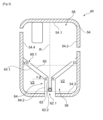
- FIG. 3 represents a sectional view of the oil reservoir 40 comprising an enclosure for the oil 54 (oil not shown here to better simplify the illustration), having a main axis R preferably corresponding to a main direction R intended to be oriented vertically in the mounting position in the turbomachine 2 of the Figure 1 .
- the enclosure 54 formed by the walls 54.1, 54.2, 54.3 and 54.4 delimiting a first compartment 56 and a second compartment 58 separated from the first compartment 56 by a separation wall 60, the latter comprises a channel 62 extending into the first compartment 56 and precisely into a conduit 64 forming an oil outlet from the first compartment.
- the main axis R corresponds to the main direction of the extent of the enclosure 54.
- the main axis R defines the direction of the largest dimension of said enclosure 54.
- the main axis R of the enclosure 54 follows the direction of gravity (perpendicular to the horizontal plane).
- the main axis R can be inclined by relative to the direction of gravity by an angle of up to 45° or exceeding 45° to form an angle of less than 90°.
- the second compartment 58 is above the first compartment 56.
- the first compartment 56 is a lower compartment 56
- the second compartment 58 is an upper compartment 58.
- the enclosure 54 of the reservoir 40 may have a substantially oblong and/or curved shape.
- the enclosure 54 comprises a substantially cylindrical shape.
- the conduit 64 extends from a bottom 54.3 of the enclosure 54 and opens into the lower compartment 56.
- the dividing wall 60 is preferably inclined relative to a perpendicular to the main direction R by an angle of inclination ⁇ of between 10° and 60°, more preferably of between 30° and 50°, and even more preferably, the angle of inclination ⁇ is equal to 45°.
- the dividing wall 60 is funnel-shaped.
- the conduit 64 comprises a distal portion 64.1 parallel to the separation wall 60 and also forming a funnel corresponding to the funnel shape of the separation wall 60, but the distal portion 64.1 may be inclined relative to said separation wall 60 by an angle of less than 20°.
- the distal end 62.1 delimits a buffer volume V' inside the conduit 64 with its distal part 64.1.
- the buffer volume V' being included between the lines illustrated in dotted lines, these lines are perpendicular to the main direction. It should be noted that the low dotted line (adjacent to the bottom 54.3) stops at the level of the distal end 62.1 of the channel 62 because in negative gravity it is at this level that the oil stops and no longer passes through the channel 62 to reach the upper compartment 58.
- the buffer volume V' is partly dependent on the difference between the sections of the channel 62 and the conduit 64.
- the conduit 64 preferably has a section corresponding to at least 1.2 times the section of the channel 62 and/or at most 3 times the section of said channel 62.
- the distal end 62.1 of the channel 62 also delimits a second volume V2 with the distal part 64.1 of the conduit 64, this second volume V2 being in the lower compartment 56 and outside the conduit 64.
- the volume V2 corresponds to the volume of oil that can be entirely consumed during a negative G phase before the oil supplying the second closed circuit is exhausted.
- the distal part 64.1 of the conduit 64 delimits with the separation wall 60 a first volume V1 inside the lower compartment 56.
- the second volume V2 is larger than the first volume V1, in order to secure a maximum quantity of oil in the lower compartment 56 in order to supply the variable timing systems of the turbomachine without interruption.
- Figure 4 represents a sectional view of the oil reservoir 40 of the Figure 3 during a phase of flight of the aircraft in positive G.
- G+ will refer to positive gravity and G- to negative gravity.
- the reservoir 40 is capable of ensuring a constant supply of pure oil during G- flight phases, and each of the G- phases lasts between a fraction of a second and 45 seconds.
- the reservoir 40 can be sized so as to ensure a constant supply of oil even beyond 45 seconds.
- the oil tank 40 comprises an oil inlet 66 mixed with air directed towards the upper compartment 58, and precisely towards an oil deaerator device 68, making it possible to evacuate the air 70 which can be mixed with the oil.
- the oil inlet preferably comes from the at least one recovery pump 46 of the Figure 2 .
- the reservoir 40 further comprises an upper oil outlet 72 forming with the oil inlet 66 and the upper compartment 58 the first closed circuit 42 of the Figure 2 .
- the upper oil outlet 72 is close to the separation wall 60 so as to maintain the supply of said outlet 72 under all circumstances, in particular during a return to the G+ after a G- event.
- the turbomachine of the invention is capable of ensuring continuous and secure operation of its variable timing systems thanks to the main oil reservoir making it possible to ensure oil supply in order to supply such systems with pure oil without any presence of air and without interruption of supply during flight phases in zero or negative gravity.
Landscapes
- Engineering & Computer Science (AREA)
- Mechanical Engineering (AREA)
- General Engineering & Computer Science (AREA)
- Chemical & Material Sciences (AREA)
- Combustion & Propulsion (AREA)
- General Details Of Gearings (AREA)
- Structures Of Non-Positive Displacement Pumps (AREA)
Claims (14)
- Ein Öltank (40) für eine Turbomaschine (2), der Folgendes umfasst:- ein Ölgehäuse (54) mit einer Hauptachse (R) und Wänden (54.1, 54.2, 54.3, 54.4), die eine erste Kammer (56) und eine zweite Kammer (58) begrenzen, die von der ersten Kammer (56) durch eine Trennwand (60) getrennt ist;- eine Leitung (62), die von der Trennwand (60) zur ersten Kammer (56) führt;- einen Lufteinlass für gemischtes Öl (66), der sich in der zweiten Kammer (58) befindet;- einen Ölauslass (74), der aus einem Kanal (64) besteht, der zur ersten Kammer (56) führt;dadurch gekennzeichnet, dass
die Leitung (62) sich in dem Kanal (64) erstreckt, um eine Ölversorgung für den Kanal (64) bereitzustellen und dadurch die Ölversorgung für den Kanal (64) während Flugphasen mit Schwerelosigkeit oder negativer Schwerkraft aufrechtzuerhalten. - Der Öltank (40) nach Anspruch 1, wobei die Trennwand (60) in Bezug auf eine Senkrechte zur Hauptachse (R) der Leitung (62) geneigt ist, um Öl zu der Leitung (62) zu leiten.
- Der Öltank (40) nach Anspruch 2, wobei die Trennwand (60) einen Neigungswinkel (α) in Bezug auf die Senkrechte zur Hauptachse (R) zwischen 10° und 60°, vorzugsweise zwischen 30° und 50°, aufweist.
- Der Öltank (40) gemäß den Ansprüchen 2 und 3, wobei der Kanal (64) einen distalen Teil (64.1) umfasst, der parallel zu der Trennwand (60) oder um weniger als 20° relativ zu der Trennwand (60) geneigt ist.
- Der Öltank (40) nach einem der Ansprüche 2 bis 4, wobei die Leitung (62) in einer zentralen Position der Trennwand (60) angeordnet ist und die Trennwand (60) trichterförmig ist.
- Der Öltank (40) nach den Ansprüchen 4 und 5, wobei der distale Teil (64.1) des Kanals (64) trichterförmig ist und der Trichterform der Trennwand (60) entspricht.
- Der Öltank (40) nach einem der Ansprüche 1 bis 6, wobei der Kanal (64) einen proximalen Abschnitt (64.2) umfasst, der im Wesentlichen parallel zur Hauptachse (R) verläuft.
- Der Öltank (40) gemäß einem der Ansprüche 1 bis 7, wobei der distale Teil (64.1) des Kanals (64) mindestens 40 % der Gesamtausdehnung des Kanals (64) umfasst.
- Der Öltank (40) gemäß einem der Ansprüche 1 bis 8, wobei der Kanal (64) einen Querschnitt aufweist, der mindestens dem 1,2-fachen eines Querschnitts der Leitung (62) entspricht.
- Der Öltank (40) nach den Ansprüchen 1 bis 9, wobei die Leitung (62) ein distales Ende (62.1) aufweist, das zusammen mit dem distalen Teil (64.1) des Kanals (64) ein Puffervolumen (V') innerhalb des Kanals (64) bildet, wobei das jeweilige distale Ende (62.1) der Leitung (62) und der distalen Teil (64.1) des Kanals (64) ein zweites Volumen (V2) außerhalb des Kanals (64) bilden und der distale Teil (64.1) des Kanals (64) zusammen mit der Trennwand (60) ein erstes Volumen (V1) bildet, wobei das erste Volumen (V1) kleiner ist als das zweite Volumen (V2) in der unteren Kammer (56).
- Der Öltank (40) gemäß den Ansprüchen 1 bis 10, wobei die Trennwand (60) und/oder das distale Ende (62.1) der Leitung (62) ferner mindestens ein Ventil (60.1) und/oder mindestens ein schwerkraftempfindliches Rückschlagventil (62.2) umfasst.
- Eine Turbomaschine (2), umfassend:- eine hüllenlose Schaufel(14), die einen Einlassluftstrom (F) antreibt, wobei die Schaufel (14) ein variables Ventilsteuerungssystem (52) umfasst, das es ermöglicht, die Steigung der Schaufeln (28) des Propellers (14) zu betätigen;- einen Öltank (40) zum Schmieren von Komponenten der Turbomaschine (2);dadurch gekennzeichnet, dass der Öltank (40) einem der Ansprüche 1 bis 11 entspricht.
- Die Turbomaschine (2) gemäß Anspruch 12, dadurch gekennzeichnet, dass der Öleinlass (66) zur zweiten Kammer (58) und ein oberer Ölauslass (72) zusammen mit der zweiten Kammer (58) einen ersten geschlossenen Kreislauf (42) zum Schmieren und/oder Kühlen der Motorkomponenten (3) der Turbomaschine (2) bilden.
- Die Turbomaschine (2) gemäß einem der Ansprüche 12 oder 13, dadurch gekennzeichnet, dass das variable Ventilsteuerungssystem (52) ein erstes variables Ventilsteuerungssystem (52) ist und die Turbomaschine (2) ferner einen Gleichrichter (34) mit einer Vielzahl von Statorschaufeln (36) umfasst, die von einem feststehenden Gehäuse (24) erstrecken, wobei der Gleichrichter (34) ein zweites variables Ventilsteuerungssystem (52) umfasst, und dass der Ölauslass (74) hydraulisch mit einem zweiten geschlossenen Kreislauf (48) verbunden ist, der Komponenten des ersten (52) und/oder zweiten variablen Ventilsteuerungssystems (52) der Turbomaschine umfasst.
Priority Applications (3)
| Application Number | Priority Date | Filing Date | Title |
|---|---|---|---|
| EP22315125.9A EP4296491B1 (de) | 2022-06-24 | 2022-06-24 | Öltank für eine turbomaschine mit unterem fach mit einem negativ-g-kompatiblen ölauslasskanal |
| PCT/FR2023/000119 WO2023247846A1 (fr) | 2022-06-24 | 2023-06-21 | Reservoir d'huile pour turbomachine avec compartiment inférieur avec conduit de sortie d'huile compatible g négatif |
| CN202380049634.3A CN119585514A (zh) | 2022-06-24 | 2023-06-21 | 用于涡轮机的包括具有负g兼容的油出口管道的下隔室的油罐 |
Applications Claiming Priority (1)
| Application Number | Priority Date | Filing Date | Title |
|---|---|---|---|
| EP22315125.9A EP4296491B1 (de) | 2022-06-24 | 2022-06-24 | Öltank für eine turbomaschine mit unterem fach mit einem negativ-g-kompatiblen ölauslasskanal |
Publications (2)
| Publication Number | Publication Date |
|---|---|
| EP4296491A1 EP4296491A1 (de) | 2023-12-27 |
| EP4296491B1 true EP4296491B1 (de) | 2025-04-09 |
Family
ID=83593863
Family Applications (1)
| Application Number | Title | Priority Date | Filing Date |
|---|---|---|---|
| EP22315125.9A Active EP4296491B1 (de) | 2022-06-24 | 2022-06-24 | Öltank für eine turbomaschine mit unterem fach mit einem negativ-g-kompatiblen ölauslasskanal |
Country Status (3)
| Country | Link |
|---|---|
| EP (1) | EP4296491B1 (de) |
| CN (1) | CN119585514A (de) |
| WO (1) | WO2023247846A1 (de) |
Families Citing this family (1)
| Publication number | Priority date | Publication date | Assignee | Title |
|---|---|---|---|---|
| FR3127527B1 (fr) * | 2021-09-30 | 2023-09-01 | Safran Aircraft Engines | Reservoir auxiliaire d’huile pour une turbomachine d’aeronef |
Family Cites Families (6)
| Publication number | Priority date | Publication date | Assignee | Title |
|---|---|---|---|---|
| EP1104742B1 (de) * | 1999-12-02 | 2003-07-23 | Techspace aero | Behalter fur einen Flüssigkeitkreislauf |
| US8181746B2 (en) * | 2008-09-18 | 2012-05-22 | United Technologies Corporation | Continuous supply fluid reservoir |
| EP2801707B1 (de) * | 2013-05-10 | 2017-07-05 | Safran Aero Boosters SA | Schmierkreislauf eines Turbotriebwerks mit Überlaufventil für Windmilling |
| FR3010133B1 (fr) | 2013-09-02 | 2015-10-02 | Snecma | Reservoir comprenant une cloison inclinee munie a ses extremites d'orifices traversants pour une alimentation continue de turbomachine en liquide d'alimentation |
| FR3024497B1 (fr) * | 2014-07-31 | 2019-07-26 | Safran Aircraft Engines | Ensemble de turbomachine pour l'entrainement d'un fluide d'ecoulement deja utilise vers un element a alimenter |
| FR3107319B1 (fr) | 2020-02-19 | 2022-08-12 | Safran Aircraft Engines | Module de turbomachine equipe de systeme de changement de pas des pales d’aubes de stator |
-
2022
- 2022-06-24 EP EP22315125.9A patent/EP4296491B1/de active Active
-
2023
- 2023-06-21 WO PCT/FR2023/000119 patent/WO2023247846A1/fr not_active Ceased
- 2023-06-21 CN CN202380049634.3A patent/CN119585514A/zh active Pending
Also Published As
| Publication number | Publication date |
|---|---|
| EP4296491A1 (de) | 2023-12-27 |
| CN119585514A (zh) | 2025-03-07 |
| WO2023247846A1 (fr) | 2023-12-28 |
Similar Documents
| Publication | Publication Date | Title |
|---|---|---|
| EP2801707B1 (de) | Schmierkreislauf eines Turbotriebwerks mit Überlaufventil für Windmilling | |
| EP3377732B1 (de) | Vorderer teil einer turbomaschine | |
| FR3017159A1 (fr) | Alimentation en air d'un circuit de conditionnement d'air d'une cabine d'un aeronef a partir de son turbopropulseur | |
| EP4073366B1 (de) | Aeronautisches antriebssystem mit niedriger leckrate und verbesserter antriebseffizienz | |
| WO2020008147A1 (fr) | Système propulsif d'aéronef et aéronef propulsé par un tel système propulsif intégré à l'arrière d'un fuselage de l'aéronef | |
| WO2023052719A1 (fr) | Turbomachine comprenant un systeme d'alimentation en huile | |
| EP4296491B1 (de) | Öltank für eine turbomaschine mit unterem fach mit einem negativ-g-kompatiblen ölauslasskanal | |
| FR2982842A1 (fr) | Avion | |
| EP4296476B1 (de) | Öltank für eine g-negativ kompatible turbomaschine mit zyklonabscheider | |
| EP4296475B1 (de) | Öltank mit unterem fach mit einem negativ-g-kompatiblen öl-austrittskanal | |
| FR3036144A1 (fr) | Helice de turbomachine | |
| EP4569214A1 (de) | Flugzeugturbinentriebwerk | |
| FR3143661A1 (fr) | système PROPULSIF AERONAUTIQUE | |
| WO2024003475A1 (fr) | Reservoir d'huile pour turbomachine avec roue centrifugeuse compatible g negatif | |
| FR3143001A1 (fr) | Module de turbomachine equipe d’un accumulateur hydraulique et turbomachine le comportant | |
| EP4409115A1 (de) | Hilfsöltank für ein flugzeugturbinentriebwerk | |
| EP4229286B1 (de) | Aeronautisches antriebssystem mit verbesserter antriebseffizienz | |
| WO2024227580A1 (fr) | Ensemble de pompage de fluide dans un compartiment interne de turbomachine | |
| FR2966522A1 (fr) | Turbomachine a double soufflante et triple flux | |
| WO2024224027A2 (fr) | Carter pour une turbomachine d'aeronef | |
| WO2025114656A1 (fr) | Ensemble et procédé de drainage par effet venturi pour turbomachine | |
| FR3143660A1 (fr) | système PROPULSIF AERONAUTIQUE | |
| FR3143659A1 (fr) | système PROPULSIF AERONAUTIQUE | |
| FR3143663A1 (fr) | système PROPULSIF AERONAUTIQUE | |
| FR3143658A1 (fr) | système PROPULSIF AERONAUTIQUE |
Legal Events
| Date | Code | Title | Description |
|---|---|---|---|
| PUAI | Public reference made under article 153(3) epc to a published international application that has entered the european phase |
Free format text: ORIGINAL CODE: 0009012 |
|
| STAA | Information on the status of an ep patent application or granted ep patent |
Free format text: STATUS: THE APPLICATION HAS BEEN PUBLISHED |
|
| AK | Designated contracting states |
Kind code of ref document: A1 Designated state(s): AL AT BE BG CH CY CZ DE DK EE ES FI FR GB GR HR HU IE IS IT LI LT LU LV MC MK MT NL NO PL PT RO RS SE SI SK SM TR |
|
| STAA | Information on the status of an ep patent application or granted ep patent |
Free format text: STATUS: REQUEST FOR EXAMINATION WAS MADE |
|
| 17P | Request for examination filed |
Effective date: 20240626 |
|
| RBV | Designated contracting states (corrected) |
Designated state(s): AL AT BE BG CH CY CZ DE DK EE ES FI FR GB GR HR HU IE IS IT LI LT LU LV MC MK MT NL NO PL PT RO RS SE SI SK SM TR |
|
| REG | Reference to a national code |
Ref country code: DE Ref legal event code: R079 Free format text: PREVIOUS MAIN CLASS: F02C0007060000 Ipc: F01D0025180000 Ref country code: DE Ref legal event code: R079 Ref document number: 602022012873 Country of ref document: DE Free format text: PREVIOUS MAIN CLASS: F02C0007060000 Ipc: F01D0025180000 |
|
| RIC1 | Information provided on ipc code assigned before grant |
Ipc: F02C 7/06 20060101ALI20240924BHEP Ipc: F01M 11/00 20060101ALI20240924BHEP Ipc: F04D 29/063 20060101ALI20240924BHEP Ipc: F01D 25/18 20060101AFI20240924BHEP |
|
| GRAP | Despatch of communication of intention to grant a patent |
Free format text: ORIGINAL CODE: EPIDOSNIGR1 |
|
| STAA | Information on the status of an ep patent application or granted ep patent |
Free format text: STATUS: GRANT OF PATENT IS INTENDED |
|
| INTG | Intention to grant announced |
Effective date: 20241105 |
|
| GRAS | Grant fee paid |
Free format text: ORIGINAL CODE: EPIDOSNIGR3 |
|
| GRAA | (expected) grant |
Free format text: ORIGINAL CODE: 0009210 |
|
| STAA | Information on the status of an ep patent application or granted ep patent |
Free format text: STATUS: THE PATENT HAS BEEN GRANTED |
|
| AK | Designated contracting states |
Kind code of ref document: B1 Designated state(s): AL AT BE BG CH CY CZ DE DK EE ES FI FR GB GR HR HU IE IS IT LI LT LU LV MC MK MT NL NO PL PT RO RS SE SI SK SM TR |
|
| REG | Reference to a national code |
Ref country code: GB Ref legal event code: FG4D Free format text: NOT ENGLISH |
|
| REG | Reference to a national code |
Ref country code: CH Ref legal event code: EP |
|
| REG | Reference to a national code |
Ref country code: DE Ref legal event code: R096 Ref document number: 602022012873 Country of ref document: DE |
|
| REG | Reference to a national code |
Ref country code: IE Ref legal event code: FG4D Free format text: LANGUAGE OF EP DOCUMENT: FRENCH |
|
| PGFP | Annual fee paid to national office [announced via postgrant information from national office to epo] |
Ref country code: DE Payment date: 20250618 Year of fee payment: 4 |
|
| PGFP | Annual fee paid to national office [announced via postgrant information from national office to epo] |
Ref country code: BE Payment date: 20250624 Year of fee payment: 4 |
|
| PGFP | Annual fee paid to national office [announced via postgrant information from national office to epo] |
Ref country code: FR Payment date: 20250620 Year of fee payment: 4 |
|
| PGFP | Annual fee paid to national office [announced via postgrant information from national office to epo] |
Ref country code: AT Payment date: 20250721 Year of fee payment: 4 |
|
| REG | Reference to a national code |
Ref country code: NL Ref legal event code: MP Effective date: 20250409 |
|
| PG25 | Lapsed in a contracting state [announced via postgrant information from national office to epo] |
Ref country code: NL Free format text: LAPSE BECAUSE OF FAILURE TO SUBMIT A TRANSLATION OF THE DESCRIPTION OR TO PAY THE FEE WITHIN THE PRESCRIBED TIME-LIMIT Effective date: 20250409 |
|
| REG | Reference to a national code |
Ref country code: AT Ref legal event code: MK05 Ref document number: 1783671 Country of ref document: AT Kind code of ref document: T Effective date: 20250409 |
|
| PG25 | Lapsed in a contracting state [announced via postgrant information from national office to epo] |
Ref country code: FI Free format text: LAPSE BECAUSE OF FAILURE TO SUBMIT A TRANSLATION OF THE DESCRIPTION OR TO PAY THE FEE WITHIN THE PRESCRIBED TIME-LIMIT Effective date: 20250409 Ref country code: PT Free format text: LAPSE BECAUSE OF FAILURE TO SUBMIT A TRANSLATION OF THE DESCRIPTION OR TO PAY THE FEE WITHIN THE PRESCRIBED TIME-LIMIT Effective date: 20250811 Ref country code: ES Free format text: LAPSE BECAUSE OF FAILURE TO SUBMIT A TRANSLATION OF THE DESCRIPTION OR TO PAY THE FEE WITHIN THE PRESCRIBED TIME-LIMIT Effective date: 20250409 |
|
| REG | Reference to a national code |
Ref country code: LT Ref legal event code: MG9D |
|
| PG25 | Lapsed in a contracting state [announced via postgrant information from national office to epo] |
Ref country code: NO Free format text: LAPSE BECAUSE OF FAILURE TO SUBMIT A TRANSLATION OF THE DESCRIPTION OR TO PAY THE FEE WITHIN THE PRESCRIBED TIME-LIMIT Effective date: 20250709 Ref country code: GR Free format text: LAPSE BECAUSE OF FAILURE TO SUBMIT A TRANSLATION OF THE DESCRIPTION OR TO PAY THE FEE WITHIN THE PRESCRIBED TIME-LIMIT Effective date: 20250710 |
|
| PG25 | Lapsed in a contracting state [announced via postgrant information from national office to epo] |
Ref country code: PL Free format text: LAPSE BECAUSE OF FAILURE TO SUBMIT A TRANSLATION OF THE DESCRIPTION OR TO PAY THE FEE WITHIN THE PRESCRIBED TIME-LIMIT Effective date: 20250409 |
|
| PG25 | Lapsed in a contracting state [announced via postgrant information from national office to epo] |
Ref country code: BG Free format text: LAPSE BECAUSE OF FAILURE TO SUBMIT A TRANSLATION OF THE DESCRIPTION OR TO PAY THE FEE WITHIN THE PRESCRIBED TIME-LIMIT Effective date: 20250409 |
|
| PG25 | Lapsed in a contracting state [announced via postgrant information from national office to epo] |
Ref country code: HR Free format text: LAPSE BECAUSE OF FAILURE TO SUBMIT A TRANSLATION OF THE DESCRIPTION OR TO PAY THE FEE WITHIN THE PRESCRIBED TIME-LIMIT Effective date: 20250409 Ref country code: AT Free format text: LAPSE BECAUSE OF FAILURE TO SUBMIT A TRANSLATION OF THE DESCRIPTION OR TO PAY THE FEE WITHIN THE PRESCRIBED TIME-LIMIT Effective date: 20250409 |
|
| PG25 | Lapsed in a contracting state [announced via postgrant information from national office to epo] |
Ref country code: RS Free format text: LAPSE BECAUSE OF FAILURE TO SUBMIT A TRANSLATION OF THE DESCRIPTION OR TO PAY THE FEE WITHIN THE PRESCRIBED TIME-LIMIT Effective date: 20250709 |
|
| PG25 | Lapsed in a contracting state [announced via postgrant information from national office to epo] |
Ref country code: IS Free format text: LAPSE BECAUSE OF FAILURE TO SUBMIT A TRANSLATION OF THE DESCRIPTION OR TO PAY THE FEE WITHIN THE PRESCRIBED TIME-LIMIT Effective date: 20250809 |
|
| PG25 | Lapsed in a contracting state [announced via postgrant information from national office to epo] |
Ref country code: LV Free format text: LAPSE BECAUSE OF FAILURE TO SUBMIT A TRANSLATION OF THE DESCRIPTION OR TO PAY THE FEE WITHIN THE PRESCRIBED TIME-LIMIT Effective date: 20250409 |
|
| REG | Reference to a national code |
Ref country code: DE Ref legal event code: R097 Ref document number: 602022012873 Country of ref document: DE |
|
| PG25 | Lapsed in a contracting state [announced via postgrant information from national office to epo] |
Ref country code: SM Free format text: LAPSE BECAUSE OF FAILURE TO SUBMIT A TRANSLATION OF THE DESCRIPTION OR TO PAY THE FEE WITHIN THE PRESCRIBED TIME-LIMIT Effective date: 20250409 Ref country code: DK Free format text: LAPSE BECAUSE OF FAILURE TO SUBMIT A TRANSLATION OF THE DESCRIPTION OR TO PAY THE FEE WITHIN THE PRESCRIBED TIME-LIMIT Effective date: 20250409 |
|
| PG25 | Lapsed in a contracting state [announced via postgrant information from national office to epo] |
Ref country code: CZ Free format text: LAPSE BECAUSE OF FAILURE TO SUBMIT A TRANSLATION OF THE DESCRIPTION OR TO PAY THE FEE WITHIN THE PRESCRIBED TIME-LIMIT Effective date: 20250409 |
|
| PG25 | Lapsed in a contracting state [announced via postgrant information from national office to epo] |
Ref country code: EE Free format text: LAPSE BECAUSE OF FAILURE TO SUBMIT A TRANSLATION OF THE DESCRIPTION OR TO PAY THE FEE WITHIN THE PRESCRIBED TIME-LIMIT Effective date: 20250409 |
|
| PG25 | Lapsed in a contracting state [announced via postgrant information from national office to epo] |
Ref country code: SK Free format text: LAPSE BECAUSE OF FAILURE TO SUBMIT A TRANSLATION OF THE DESCRIPTION OR TO PAY THE FEE WITHIN THE PRESCRIBED TIME-LIMIT Effective date: 20250409 |
|
| REG | Reference to a national code |
Ref country code: CH Ref legal event code: H13 Free format text: ST27 STATUS EVENT CODE: U-0-0-H10-H13 (AS PROVIDED BY THE NATIONAL OFFICE) Effective date: 20260127 |
|
| PG25 | Lapsed in a contracting state [announced via postgrant information from national office to epo] |
Ref country code: IT Free format text: LAPSE BECAUSE OF FAILURE TO SUBMIT A TRANSLATION OF THE DESCRIPTION OR TO PAY THE FEE WITHIN THE PRESCRIBED TIME-LIMIT Effective date: 20250409 |
|
| PG25 | Lapsed in a contracting state [announced via postgrant information from national office to epo] |
Ref country code: MC Free format text: LAPSE BECAUSE OF FAILURE TO SUBMIT A TRANSLATION OF THE DESCRIPTION OR TO PAY THE FEE WITHIN THE PRESCRIBED TIME-LIMIT Effective date: 20250409 |
|
| PLBE | No opposition filed within time limit |
Free format text: ORIGINAL CODE: 0009261 |
|
| STAA | Information on the status of an ep patent application or granted ep patent |
Free format text: STATUS: NO OPPOSITION FILED WITHIN TIME LIMIT |
|
| PG25 | Lapsed in a contracting state [announced via postgrant information from national office to epo] |
Ref country code: LU Free format text: LAPSE BECAUSE OF NON-PAYMENT OF DUE FEES Effective date: 20250624 |
|
| REG | Reference to a national code |
Ref country code: CH Ref legal event code: L10 Free format text: ST27 STATUS EVENT CODE: U-0-0-L10-L00 (AS PROVIDED BY THE NATIONAL OFFICE) Effective date: 20260218 |
|
| PG25 | Lapsed in a contracting state [announced via postgrant information from national office to epo] |
Ref country code: RO Free format text: LAPSE BECAUSE OF FAILURE TO SUBMIT A TRANSLATION OF THE DESCRIPTION OR TO PAY THE FEE WITHIN THE PRESCRIBED TIME-LIMIT Effective date: 20250409 |
|
| 26N | No opposition filed |
Effective date: 20260112 |
|
| PG25 | Lapsed in a contracting state [announced via postgrant information from national office to epo] |
Ref country code: IE Free format text: LAPSE BECAUSE OF NON-PAYMENT OF DUE FEES Effective date: 20250624 |