EP4296482A1 - Vehicle and thermal management control method and device therefor, and storage medium - Google Patents
Vehicle and thermal management control method and device therefor, and storage medium Download PDFInfo
- Publication number
- EP4296482A1 EP4296482A1 EP22794781.9A EP22794781A EP4296482A1 EP 4296482 A1 EP4296482 A1 EP 4296482A1 EP 22794781 A EP22794781 A EP 22794781A EP 4296482 A1 EP4296482 A1 EP 4296482A1
- Authority
- EP
- European Patent Office
- Prior art keywords
- engine
- water pump
- thermal management
- current
- preset
- Prior art date
- Legal status (The legal status is an assumption and is not a legal conclusion. Google has not performed a legal analysis and makes no representation as to the accuracy of the status listed.)
- Granted
Links
Images

Classifications
-
- F—MECHANICAL ENGINEERING; LIGHTING; HEATING; WEAPONS; BLASTING
- F01—MACHINES OR ENGINES IN GENERAL; ENGINE PLANTS IN GENERAL; STEAM ENGINES
- F01P—COOLING OF MACHINES OR ENGINES IN GENERAL; COOLING OF INTERNAL-COMBUSTION ENGINES
- F01P7/00—Controlling of coolant flow
- F01P7/14—Controlling of coolant flow the coolant being liquid
- F01P7/16—Controlling of coolant flow the coolant being liquid by thermostatic control
- F01P7/167—Controlling of coolant flow the coolant being liquid by thermostatic control by adjusting the pre-set temperature according to engine parameters, e.g. engine load, engine speed
-
- F—MECHANICAL ENGINEERING; LIGHTING; HEATING; WEAPONS; BLASTING
- F01—MACHINES OR ENGINES IN GENERAL; ENGINE PLANTS IN GENERAL; STEAM ENGINES
- F01P—COOLING OF MACHINES OR ENGINES IN GENERAL; COOLING OF INTERNAL-COMBUSTION ENGINES
- F01P5/00—Pumping cooling-air or liquid coolants
- F01P5/10—Pumping liquid coolant; Arrangements of coolant pumps
-
- F—MECHANICAL ENGINEERING; LIGHTING; HEATING; WEAPONS; BLASTING
- F01—MACHINES OR ENGINES IN GENERAL; ENGINE PLANTS IN GENERAL; STEAM ENGINES
- F01P—COOLING OF MACHINES OR ENGINES IN GENERAL; COOLING OF INTERNAL-COMBUSTION ENGINES
- F01P11/00—Component parts, details, or accessories not provided for in, or of interest apart from, groups F01P1/00 - F01P9/00
- F01P11/14—Indicating devices; Other safety devices
- F01P11/18—Indicating devices; Other safety devices concerning coolant pressure, coolant flow, or liquid-coolant level
-
- F—MECHANICAL ENGINEERING; LIGHTING; HEATING; WEAPONS; BLASTING
- F01—MACHINES OR ENGINES IN GENERAL; ENGINE PLANTS IN GENERAL; STEAM ENGINES
- F01P—COOLING OF MACHINES OR ENGINES IN GENERAL; COOLING OF INTERNAL-COMBUSTION ENGINES
- F01P7/00—Controlling of coolant flow
- F01P7/14—Controlling of coolant flow the coolant being liquid
- F01P7/16—Controlling of coolant flow the coolant being liquid by thermostatic control
- F01P7/162—Controlling of coolant flow the coolant being liquid by thermostatic control by cutting in and out of pumps
-
- F—MECHANICAL ENGINEERING; LIGHTING; HEATING; WEAPONS; BLASTING
- F01—MACHINES OR ENGINES IN GENERAL; ENGINE PLANTS IN GENERAL; STEAM ENGINES
- F01P—COOLING OF MACHINES OR ENGINES IN GENERAL; COOLING OF INTERNAL-COMBUSTION ENGINES
- F01P7/00—Controlling of coolant flow
- F01P7/14—Controlling of coolant flow the coolant being liquid
- F01P7/16—Controlling of coolant flow the coolant being liquid by thermostatic control
- F01P7/164—Controlling of coolant flow the coolant being liquid by thermostatic control by varying pump speed
-
- F—MECHANICAL ENGINEERING; LIGHTING; HEATING; WEAPONS; BLASTING
- F01—MACHINES OR ENGINES IN GENERAL; ENGINE PLANTS IN GENERAL; STEAM ENGINES
- F01P—COOLING OF MACHINES OR ENGINES IN GENERAL; COOLING OF INTERNAL-COMBUSTION ENGINES
- F01P2025/00—Measuring
- F01P2025/08—Temperature
- F01P2025/13—Ambient temperature
-
- F—MECHANICAL ENGINEERING; LIGHTING; HEATING; WEAPONS; BLASTING
- F01—MACHINES OR ENGINES IN GENERAL; ENGINE PLANTS IN GENERAL; STEAM ENGINES
- F01P—COOLING OF MACHINES OR ENGINES IN GENERAL; COOLING OF INTERNAL-COMBUSTION ENGINES
- F01P2025/00—Measuring
- F01P2025/08—Temperature
- F01P2025/32—Engine outcoming fluid temperature
-
- F—MECHANICAL ENGINEERING; LIGHTING; HEATING; WEAPONS; BLASTING
- F01—MACHINES OR ENGINES IN GENERAL; ENGINE PLANTS IN GENERAL; STEAM ENGINES
- F01P—COOLING OF MACHINES OR ENGINES IN GENERAL; COOLING OF INTERNAL-COMBUSTION ENGINES
- F01P2025/00—Measuring
- F01P2025/08—Temperature
- F01P2025/50—Temperature using two or more temperature sensors
-
- F—MECHANICAL ENGINEERING; LIGHTING; HEATING; WEAPONS; BLASTING
- F01—MACHINES OR ENGINES IN GENERAL; ENGINE PLANTS IN GENERAL; STEAM ENGINES
- F01P—COOLING OF MACHINES OR ENGINES IN GENERAL; COOLING OF INTERNAL-COMBUSTION ENGINES
- F01P2025/00—Measuring
- F01P2025/60—Operating parameters
- F01P2025/62—Load
-
- F—MECHANICAL ENGINEERING; LIGHTING; HEATING; WEAPONS; BLASTING
- F01—MACHINES OR ENGINES IN GENERAL; ENGINE PLANTS IN GENERAL; STEAM ENGINES
- F01P—COOLING OF MACHINES OR ENGINES IN GENERAL; COOLING OF INTERNAL-COMBUSTION ENGINES
- F01P2025/00—Measuring
- F01P2025/60—Operating parameters
- F01P2025/66—Vehicle speed
-
- F—MECHANICAL ENGINEERING; LIGHTING; HEATING; WEAPONS; BLASTING
- F01—MACHINES OR ENGINES IN GENERAL; ENGINE PLANTS IN GENERAL; STEAM ENGINES
- F01P—COOLING OF MACHINES OR ENGINES IN GENERAL; COOLING OF INTERNAL-COMBUSTION ENGINES
- F01P2037/00—Controlling
-
- F—MECHANICAL ENGINEERING; LIGHTING; HEATING; WEAPONS; BLASTING
- F01—MACHINES OR ENGINES IN GENERAL; ENGINE PLANTS IN GENERAL; STEAM ENGINES
- F01P—COOLING OF MACHINES OR ENGINES IN GENERAL; COOLING OF INTERNAL-COMBUSTION ENGINES
- F01P2050/00—Applications
- F01P2050/22—Motor-cars
Definitions
- the present disclosure relates to the technical filed of vehicles, and specifically to a vehicle and a thermal management control method and device therefor, and a storage medium.
- a thermal management control method for an engine of a vehicle adjusts the opening of a thermostat, the rotating speed of an electronic water pump, and the rotating speed of a radiator fan according to the priority from high to low, so as to meet the heat dissipation requirements under various working conditions.
- the problem of how to make the thermal management system have the minimum power consumption while the engine is ensured not to suffer from local overheat during a warm-up process of the engine is not considered.
- a first object of the present disclosure is to provide a thermal management control method for a vehicle, which avoids the local overheat of an engine and allows a thermal management system to be in a minimum power consumption state by controlling a water pump to periodically switch between a start state and a stop state, when the engine is in a warm-up mode of high power, and low vehicle speed.
- a second object of the present disclosure is to provide a computer-readable storage medium.
- a third object of the present disclosure is to provide a thermal management control device for a vehicle.
- a fourth object of the present disclosure is to provide a vehicle.
- an embodiment of the present disclosure provides a thermal management control method for a vehicle.
- the vehicle includes an engine and a thermal management system.
- the thermal management system includes a water pump.
- the engine and the water pump are connected to form a first cooling circulation.
- the control method includes: when a current temperature of the engine is less than or equal to a preset temperature threshold, a total engine power is greater than or equal to a preset power threshold, and a current vehicle speed is less than or equal to a preset vehicle speed threshold, controlling a water pump to periodically switch between a start state and a stop state.
- the engine When the current temperature of the engine is less than or equal to a preset temperature threshold, the total engine power is greater than or equal to a preset power threshold, and the current vehicle speed is less than or equal to a preset vehicle speed threshold, the engine is considered to be in a warm-up state of high power and low vehicle speed.
- the water pump By controlling the water pump to periodically switch between a start state and a stop state, the local overheat of the engine is avoided and the thermal management system is allowed to be in a minimum power consumption state.
- an embodiment of the present disclosure provides a computer-readable storage medium.
- the computer-readable storage medium stores a computer program, which is executable by a processor to implement the thermal management control method according to the embodiment in the first aspect.
- an embodiment of the present disclosure provides a thermal management control device for a vehicle.
- the thermal management control device includes a processor, and a storage connected to the processor, where the storage stores a computer program including program instructions, and the processor is configured to call the program instructions to implement the thermal management control method according to the embodiment in the first aspect.
- an embodiment of the present disclosure provides a vehicle.
- the vehicle includes an engine and a thermal management system.
- the thermal management system includes a water pump, an air-cooling radiator, a thermostat, and a thermal management control device according to the embodiment in the third aspect.
- a vehicle 100, and a thermal management control method and a thermal management control device therefor, and a computer-readable storage medium according to the embodiments of the present disclosure are described below with reference to FIGs. 1 and 2 .
- the vehicle 100 includes an engine 110 and a thermal management system 120.
- the thermal management system 120 includes a water pump 121, an air-cooling radiator 122, a thermostat 123 and a thermal management control device 124.
- the thermal management control device 124 includes a processor 124a and a storage 124b.
- the processor 124a and the storage 124b are connected to each other.
- the storage 124b is configured to store a computer program including program instructions
- the processor 124a is configured to call the program instructions to implement the thermal management control method provided in the embodiment.
- the computer-readable storage medium provided in the embodiment of the present disclosure stores a computer program, which is executable by the processor to implement the thermal management control method according to the embodiment of the present disclosure.
- the engine 110 and the water pump 121 are connected to form a first cooling circulation. That is, a coolant is pumped by the water pump 121 to pass by the engine 110 and cool the engine 110.
- the air-cooling radiator 122 is connected to the engine 110 and the water pump 121 through the thermostat123 to form a second cooling circulation, That is, when the thermostat 123 is started, the coolant is pumped by the water pump 121 to pass by the engine 110 and cool the engine 110, and then pass through the thermostat 123 and enter the air-cooling radiator122 for being cooled.
- the first cooling circulation is a small circulation for cooling the engine 110
- the second cooling circulation is a large circulation for cooling the engine 110.
- the thermal management control method provided in the embodiment of the present disclosure includes Step S1: When a current temperature of the engine is less than or equal to a preset temperature threshold, a total engine power is greater than or equal to a preset power threshold, and a current vehicle speed is less than or equal to a preset vehicle speed threshold, the water pump is controlled to periodically switch between a start state and a stop state.
- the engine 110 When the current temperature of the engine is less than or equal to a preset temperature threshold, the engine 110 is considered to be in a warm-up state.
- the total engine power is greater than or equal to a preset power threshold and the current vehicle speed is less than or equal to a preset vehicle speed threshold, that is, the engine 110 is in a state of high power and low vehicle speed, the engine 110 has a low heat dissipation requirement, but a risk of local overheat.
- the water pump 121 by controlling the water pump 121 to periodically switch between a start state and a stop state, the local overheat of the engine 110 is avoided, and extended warm-up time of the engine 110 and increased power consumption of the thermal management system 120 caused by excessive heat dissipation are avoided.
- the thermal management system 120 is ensured to have a minimum power consumption.
- the temperature-related parameter of the engine 110 in the present disclosure is the temperature of the coolant flowing out of the engine 110.
- the preset temperature threshold may be 60°C-80°C
- the preset power threshold may be 5 kW-8 kW
- the preset vehicle speed threshold may be 5 km/h-10 km/h.
- the preset temperature threshold may be 80°C
- the preset power threshold may be 5 kW
- the preset vehicle speed threshold may be 5 km/h.
- Step S1 includes: When the water pump is in the start state, the rotational speed of the water pump is a safe rotational speed of the water pump.
- the safe rotational speed of the water pump is a rotational speed with a safe flow rate.
- the safe flow rate means the minimum flow rate required by cooling of the cylinder body and the cylinder cover of the engine at a certain load, that is, a flow rate without local overheat and boiling.
- the safe rotational speed of the water pump is determined by looking up in MAP of safe rotational speed of the water pump according to a current rotational speed of the engine and a current torque of the engine.
- MAP of safe rotational speed of the water pump is specified by simulation and experiment in the research, development and design stage according to the specific situation of the engine 110 for the purpose of achieving the minimum flow rate for cooling the engine 110 to avoid local overheat, which is preset in the thermal management control device 124.
- Step S1 includes: after the water pump is in the start state for a start time, controlling the water pump to switch to the stop state; and after the water pump is in the stop state for a stop time, controlling the water pump to switch to the start state.
- the start time and the stop time are both preset fixed values. Since the time when the engine 110 is in the warm-up state of high power and low vehicle speed is not very long, the start time and the stop time are specified by simulation and experiment in the research, development and design stage according to the specific situation of the engine 110, which are preset in the thermal management control device 124. This can meet the basic requirements, and simplify the control program.
- the start time positively correlates with the current vehicle speed and the stop time inversely correlates with the current vehicle speed. Obviously, the higher the current vehicle speed is, the higher the heat dissipation requirement of the engine 110 will be. Therefore, by increasing the start time and reducing the stop time, the thermal management system 120 can be ensured to be in the minimum power consumption state more accurately.
- the thermal management control method provided in the embodiment of the present disclosure further includes Step S2: When the current temperature of the engine is less than or equal to the preset temperature threshold, the rotational speed of the air-cooling radiator is controlled to 0, and the opening of the thermostat is controlled to 0. It should be noted that the rotational speed of the air-cooling radiator 122 refers to the rotational speed of a fan in the air-cooling radiator 122.
- the engine 110 When the current temperature of the engine is less than or equal to the preset temperature threshold, the engine 110 is considered to be in the warm-up state. That is to say, the engine 110 has a low heat dissipation requirement, and the engine 110 can be warmed up by its own heat. Therefore, the rotational speed of the air-cooling radiator 122 is controlled to 0, and the opening of the thermostat 123 is controlled to 0, such that the engine 110 does not participate in the cooling in the second cooling circulation, thereby ensuring that the thermal management system 120 is in the minimum power consumption state.
- the thermal management control method provided in the embodiment of the present disclosure further includes Step S3: When the current temperature of the engine is less than or equal to the preset temperature threshold, and the total engine power is less than the preset power threshold, the water pump is controlled to stop.
- the engine 110 When the current temperature of the engine is less than or equal to the preset temperature threshold, and the total engine power is less than the preset power threshold, the engine 110 is considered to be in a warm-up state of low power. At this time, the heat generated by the engine 110 is relatively small and can be completely used for the warm-up of the engine 110. Moreover, there is no risk of local overheat, i.e. no cooling is required. Therefore, by controlling the water pump 121 to stop, the thermal management system 120 is ensured to be in the minimum power consumption state.
- the thermal management control method provided in the embodiment of the present disclosure further includes Step S4: When the current temperature of the engine is less than or equal to the preset temperature threshold, the total engine power is greater than or equal to the preset power threshold, and the current vehicle speed is greater than the preset vehicle speed threshold, the rotational speed of the water pump is controlled to be the safe rotational speed of the water pump.
- the engine 110 When the current temperature of the engine is less than or equal to the preset temperature threshold, the total engine power is greater than or equal to the preset power threshold, and the current vehicle speed is greater than the preset vehicle speed threshold, the engine 110 is considered to be in a warm-up state of high power and high vehicle speed, the engine 110 has a high risk of local overheat, compared with the case in the high-power, low-vehicle speed state. Therefore, by controlling the rotational speed of the water pump 121 to be the safe rotational speed of the water pump, a safe flow rate at which the engine 110 has no local overheat is ensured, and the thermal management system 120 is ensured to be in the minimum power consumption state.
- Step S4 can be replaced by Step S4a:
- the rotational speed of the water pump is controlled to be greater than or equal to the safe rotational speed of the water pump and positively correlate with the current vehicle speed.
- the thermal management control method provided in the embodiment of the present disclosure further includes the following Steps S5 to S7.
- a total target heat dissipation is determined by looking up in MAP of minimum fuel consumption of the engine according to the current rotational speed of the engine, the current torque of the engine, and a current ambient temperature.
- the preset opening threshold can be 95%-100%, and particularly, 100%. That is, the thermostat 123 is fully open.
- the engine 110 When the temperature of the engine 110 is greater than or equal to the preset temperature threshold, the engine 110 is considered to complete the warm-up process. At this time, the thermal management system 120 needs to continuously control the temperature of the engine 110. When the opening of the thermostat 123 is greater than or equal to the preset opening threshold, the engine 110 is considered to enter an operating state with a high heat dissipation requirement. At this time, both the water pump 121 and the air-cooling radiator 122 need to participate in the cooling of the engine 110 and the engine 110 needs to have the minimum fuel consumption, that is, in the most efficient operating state.
- MAP of minimum fuel consumption of the engine is specified by simulation and experiment in the research, development and design stage according to the specific situation of the vehicle 100 for the purpose of achieving the minimum fuel consumption of the engine 110, which is preset in the thermal management control device 124.
- the current ambient temperature refers to the air temperature outside the vehicle, that is, the inlet temperature of the engine 110 and the air intake temperature of the air-cooling radiator 122.
- a target rotational speed of the water pump and a target rotational speed of the air-cooling radiator are determined by looking up in MAP of minimum power consumption of the thermal management system according to the total target heat dissipation, an air intake flow rate of the air-cooling radiator, and the current ambient temperature.
- the engine 110 When the opening of the thermostat 123 is greater than or equal to the preset opening threshold, the engine 110 is cooled by the second cooling circulation.
- the thermal management system 120 by using the total target heat dissipation, the air intake flow rate of the air-cooling radiator 122 and the current ambient temperature as input parameters, and looking up in MAP of minimum power consumption of the thermal management system, a combination of the target rotational speed of the water pump and the target rotational speed of the air-cooling radiator is outputted, such that the thermal management system 120 can work with the minimum power consumption.
- MAP of minimum power consumption of the thermal management system is specified by simulation and experiment in the research, development and design stage according to the specific situation of the thermal management system 120 for the purpose of achieving the minimum powder consumption of the thermal management system 120, which is preset in the thermal management control device 124.
- the air intake flow rate of the air-cooling radiator 122 is determined according to the current vehicle speed and an ambient air flow rate.
- the total target heat dissipation of the engine achieving the minimum fuel consumption or the highest efficiency under the current operating conditions is determined. Then, by MAP of minimum power consumption of the thermal management system, a combination of the rotational speed of the water pump 121 and the rotational speed of the air-cooling radiator 122, at which the thermal management system120 has a minimum power consumption, that is, the target rotational speed of the water pump and the target rotational speed of the air-cooling radiator, are determined.
- the water pump 121 and the air-cooling radiator 122 are controlled to operate at the target rotational speed of the water pump and the target rotational speed of the air-cooling radiator respectively, so as to realize the optimization of the power consumption of the thermal management system and the fuel consumption of the engine.
- Step S5 includes the following Steps S501 to S503.
- a target temperature of the engine is determined by looking up in MAP of minimum fuel consumption of the engine according to the current rotational speed of the engine, the current torque of the engine, and the current ambient temperature.
- the heat generated by the engine is determined according to the current rotational speed of the engine and the current torque of the engine.
- S503 The total target heat dissipation is determined according to the current temperature of the engine, the target temperature of the engine, and the heat generated by the engine.
- the target temperature of the engine 110 in an operating state of minimum fuel consumption and highest efficiency is outputted.
- the heat required by the engine from the current temperature to the target temperature is calculated to be C ⁇ M ⁇ T, where C is the specific heat capacity of the coolant, and M is the weight of the coolant, which depends on the flow rate. Therefore, the total target heat dissipation when the engine is cooled can be obtained by the heat generated by the engine minus C ⁇ M ⁇ T.
- the thermal management control method provided in the embodiment of the present disclosure further includes the following Steps S8 to S11.
- a target temperature of the engine is determined by looking up in MAP of minimum fuel consumption of the engine according to the current rotational speed of the engine, the current torque of the engine, and the current ambient temperature.
- a target opening of the thermostat is determined according to the current temperature of the engine and the target temperature of the engine.
- the engine 110 When the temperature of the engine 110 is greater than or equal to the preset temperature threshold and the opening of the thermostat 123 is less than the preset opening threshold, the engine 110 is considered to complete the warm-up process. However, the engine 110 has not entered an operating state with a high heat dissipation requirement yet. At this time, by controlling the opening of the thermostat 123, the engine 110 reaches the target temperature to operate in a state of the minimum fuel consumption and the highest efficiency. Moreover, since the water pump 121 operates at the lowest rotational speed and the air-cooling radiator is stopped, the thermal management system 120 is a state with the minimum power consumption.
- the thermal management control method provided in the embodiment of the present disclosure further includes the following Steps S101 to S117.
- Step S101 Whether the current temperature of the engine is less than or equal to the preset temperature threshold is determined, if yes, the engine 110 is considered to be in a warm-up stage, and Step S102 is performed; and if not, the engine is considered to complete the warm-up stage and enter a traveling stage, and Step S108 is performed.
- Step S103 Whether the total engine power is greater than or equal to the preset power threshold is determined, if yes, the engine 110 is considered to be in a warm-up mode of high power and Step S104 is performed; and if not, the engine 110 is considered to be in a warm-up mode of low power and Step S107 is performed.
- Step S104 Whether the current vehicle speed is less than or equal to the preset vehicle speed threshold is determined, if yes, the engine 110 is considered to be in a warm-up mode of high power and low vehicle speed, and Step S105 is performed; and if not, the engine 110 is considered to be in a warm-up mode of high power and high vehicle speed, and Step S106 is performed.
- the water pump When the engine 110 is in a warm-up mode of high power and low vehicle speed, the water pump is controlled to periodically switch between the start state and the stop state.
- the rotational speed of the water pump is a safe rotational speed of the water pump.
- the water pump after the water pump is in the start state for a start time, the water pump is controlled to switch to the stop state; and after the water pump is in the stop state for a stop time, the water pump is controlled to switch to the start state.
- the start time and the stop time are both preset fixed values.
- Step S108 After Step S101, when the engine 110 is in a traveling stage, whether the opening of the thermostat is greater than or equal to the preset opening threshold is determined, if yes, the engine 110 is considered to have a high heat dissipation requirement, and Step S109 is performed; and if not, the engine 110 is considered to have a low heat dissipation requirement, and Step S114 is performed.
- a target temperature of the engine is determined by looking up in MAP of minimum fuel consumption of the engine according to the current rotational speed of the engine, the current torque of the engine and the ambient temperature. It is considered that when the operating temperature of the engine 110 in the current state is the target temperature of the engine, the engine 110 is in a state of minimum fuel consumption.
- the heat generated by the engine is determined according to the current rotational speed of the engine and the current torque of the engine.
- S111 The total target heat dissipation is determined according to the current temperature of the engine, the target temperature of the engine, and the heat generated by the engine.
- a target rotational speed of the water pump and a target rotational speed of the air-cooling radiator are determined by looking up in MAP of minimum power consumption of the thermal management system according to the total target heat dissipation, the air intake flow rate of the air-cooling radiator and the ambient temperature. It is considered that with a current heat dissipation requirement and in the current environment, when the rotational speed of the water pump 121 is the target rotational speed of the water pump, and the rotational speed of the air-cooling radiator 122 is the target rotational speed of the air-cooling radiator, the thermal management system 120 is in a state of minimum power consumption.
- Step S114 After Step S108, when the engine 110 has a low heat dissipation requirement, the rotational speed of the water pump is controlled to be the safe rotational speed of the water pump, and the rotational speed of the air-cooling radiator is controlled to 0.
- a target temperature of the engine is determined by looking up in MAP of minimum fuel consumption of the engine according to the current rotational speed of the engine, the current torque of the engine and the ambient temperature.
- a target opening of the thermostat is determined according to the current temperature of the engine and the target temperature of the engine.
- the engine 110 when the current temperature of the engine is less than or equal to a preset temperature threshold, the engine 110 is considered to be in a warm-up state.
- the total engine power is greater than or equal to a preset power threshold and the current vehicle speed is less than or equal to a preset vehicle speed threshold, that is, the engine 110 is in a state of high power and low vehicle speed, the engine 110 has a low heat dissipation requirement, but a risk of local overheat.
- the thermal management system 120 is ensured to have a minimum power consumption.
- first and second are used merely for the purpose of description, and shall not be construed as indicating or implying relative importance or implying a quantity of indicated technical features Therefore, a feature restricted by “first” or “second” may explicitly indicate or implicitly include at least one of such features.
- “multiple” means at least two, for example, two or three, unless explicitly specified.
- any process or method in the flowcharts or described otherwise herein can be construed as representing one or more modules, fragments, or parts that include codes of executable instructions used to implement a specific logical function or steps of a process.
- the scope of the preferred implementations of the present disclosure includes additional implementations, where functions can be performed not in an order shown or discussed, including performing the functions basically at the same time or in reverse order according to the functions involved. This can be understood by a person skilled in the art to which the embodiments of the present disclosure pertains.
- the logic and/or steps shown in the flowcharts or described otherwise herein, for example, a sequenced list that may be considered as executable instructions used for implementing logical functions, may be specifically implemented in any computer-readable storage medium, for use by an instruction execution system, apparatus, or device (for example, a computer-based system, a system including a processor, or other systems that can obtain an instruction from the instruction execution system, apparatus or device and execute the instruction), or for use with such instruction execution systems, apparatuses, or devices.
- the "computer-readable storage medium” may be any apparatus that can include, store, communicate, propagate, or transmit programs for use by an instruction execution system, apparatus or device or for use with the instruction execution system apparatus or device.
- the computer-readable storage medium includes: an electrical connection (electronic device) having one or more wires, a portable computer diskette (magnetic apparatus), a random access memory (RAM), a read-only memory (ROM), an erasable programmable read-only memory (EPROM or flash memory), an optical fiber apparatus, and a portable compact disk read-only memory (CDROM).
- the computer-readable storage medium can even be paper or other suitable media on which the program can be printed, because the program can be obtained electronically by, for example, optically scanning paper or other media, then editing, deciphering, or processing in other suitable ways if necessary, and then storing it in a computer memory.
- parts of the present disclosure can be implemented by hardware, software, firmware, or a combination thereof.
- steps or methods can be implemented by software or firmware that is stored in a memory and executed by a proper instruction execution system.
- implementation may be performed by any one of the following technologies well known in the art or a combination thereof: a discrete logic circuit including a logic gate circuit for implementing a logic function of a data signal, a dedicated integrated circuit including a proper combination of logic gate circuits, a programmable gate array (PGA), a field programmable gate array (FPGA), and the like.
- PGA programmable gate array
- FPGA field programmable gate array
- a person of ordinary skill in the art may understand that all or some of the steps of the methods in the foregoing embodiments may be implemented by a program instructing relevant hardware.
- the program may be stored in a computer-readable storage medium. When the program is executed, one or a combination of the steps of the method embodiments are performed.
- functional units according to the embodiments of the present disclosure may be integrated in one processing module, may be physically separate from each other or may be integrated in one modules by two or more units.
- the integrated modules described above can be implemented either in the form of hardware, or software functional modules.
- the integrated module, if implemented in the form of a software program module and sold or used as a stand-alone product, may be stored in a computer-readable storage medium.
- the storage medium mentioned above may be a read-only memory, a magnetic disk, a magnetic disk or an optical disc.
Landscapes
- Engineering & Computer Science (AREA)
- Chemical & Material Sciences (AREA)
- Combustion & Propulsion (AREA)
- Mechanical Engineering (AREA)
- General Engineering & Computer Science (AREA)
- Combined Controls Of Internal Combustion Engines (AREA)
- Control Of Vehicle Engines Or Engines For Specific Uses (AREA)
- Hybrid Electric Vehicles (AREA)
- Forklifts And Lifting Vehicles (AREA)
Abstract
Description
- The present disclosure claims priority to
Chinese Patent Application No. 202110458538.7 filed on April 27, 2021 - The present disclosure relates to the technical filed of vehicles, and specifically to a vehicle and a thermal management control method and device therefor, and a storage medium.
- In related art, a thermal management control method for an engine of a vehicle adjusts the opening of a thermostat, the rotating speed of an electronic water pump, and the rotating speed of a radiator fan according to the priority from high to low, so as to meet the heat dissipation requirements under various working conditions. However, the problem of how to make the thermal management system have the minimum power consumption while the engine is ensured not to suffer from local overheat during a warm-up process of the engine is not considered.
- In view of the above technical problems, A first object of the present disclosure is to provide a thermal management control method for a vehicle, which avoids the local overheat of an engine and allows a thermal management system to be in a minimum power consumption state by controlling a water pump to periodically switch between a start state and a stop state, when the engine is in a warm-up mode of high power, and low vehicle speed.
- A second object of the present disclosure is to provide a computer-readable storage medium.
- A third object of the present disclosure is to provide a thermal management control device for a vehicle.
- A fourth object of the present disclosure is to provide a vehicle.
- To achieve the above objects, in a first aspect, an embodiment of the present disclosure provides a thermal management control method for a vehicle. The vehicle includes an engine and a thermal management system. The thermal management system includes a water pump. The engine and the water pump are connected to form a first cooling circulation. The control method includes: when a current temperature of the engine is less than or equal to a preset temperature threshold, a total engine power is greater than or equal to a preset power threshold, and a current vehicle speed is less than or equal to a preset vehicle speed threshold, controlling a water pump to periodically switch between a start state and a stop state.
- When the current temperature of the engine is less than or equal to a preset temperature threshold, the total engine power is greater than or equal to a preset power threshold, and the current vehicle speed is less than or equal to a preset vehicle speed threshold, the engine is considered to be in a warm-up state of high power and low vehicle speed. By controlling the water pump to periodically switch between a start state and a stop state, the local overheat of the engine is avoided and the thermal management system is allowed to be in a minimum power consumption state.
- To achieve the above objects, in a second aspect, an embodiment of the present disclosure provides a computer-readable storage medium. The computer-readable storage medium stores a computer program, which is executable by a processor to implement the thermal management control method according to the embodiment in the first aspect.
- To achieve the above objects, in a third aspect, an embodiment of the present disclosure provides a thermal management control device for a vehicle. The thermal management control device includes a processor, and a storage connected to the processor, where the storage stores a computer program including program instructions, and the processor is configured to call the program instructions to implement the thermal management control method according to the embodiment in the first aspect.
- To achieve the above objects, in a fourth aspect, an embodiment of the present disclosure provides a vehicle. The vehicle includes an engine and a thermal management system. The thermal management system includes a water pump, an air-cooling radiator, a thermostat, and a thermal management control device according to the embodiment in the third aspect.
- Additional aspects and advantages of the present disclosure will be partly given in the following description, some of which will become apparent from the following description, or may be learned from practices of the present disclosure.
-
-
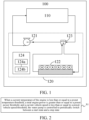
FIG. 1 is a schematic diagram of a vehicle provided in an embodiment of the present disclosure. -
FIG. 2 is a schematic flow chart of a thermal management control method provided in an embodiment of the present disclosure. -
FIG. 3 is a schematic flow chart of a thermal management control method provided in another embodiment of the present disclosure. - 100, vehicle; 110, engine; 120, thermal management system; 121, water pump; 122, air-cooling radiator; 123, thermostat; 124, thermal management control device; 124a, processor; 124b, storage.
- Embodiments of the present disclosure will be described in detail below, and examples of the embodiments are shown in accompanying drawings, where the same or similar elements or the elements having the same or similar functions are denoted by the same or similar reference numerals throughout the description. The embodiments described below with reference to the accompanying drawings are exemplary and intended to explain the present disclosure, and cannot be construed as a limitation on the present disclosure.
- A
vehicle 100, and a thermal management control method and a thermal management control device therefor, and a computer-readable storage medium according to the embodiments of the present disclosure are described below with reference toFIGs. 1 and 2 . - As shown in
FIG. 1 , thevehicle 100 includes anengine 110 and athermal management system 120. Thethermal management system 120 includes awater pump 121, an air-cooling radiator 122, athermostat 123 and a thermalmanagement control device 124. The thermalmanagement control device 124 includes aprocessor 124a and astorage 124b. Theprocessor 124a and thestorage 124b are connected to each other. Thestorage 124b is configured to store a computer program including program instructions, and theprocessor 124a is configured to call the program instructions to implement the thermal management control method provided in the embodiment. In addition, the computer-readable storage medium provided in the embodiment of the present disclosure stores a computer program, which is executable by the processor to implement the thermal management control method according to the embodiment of the present disclosure. - As shown in
FIG. 1 , theengine 110 and thewater pump 121 are connected to form a first cooling circulation. That is, a coolant is pumped by thewater pump 121 to pass by theengine 110 and cool theengine 110. The air-cooling radiator 122 is connected to theengine 110 and thewater pump 121 through the thermostat123 to form a second cooling circulation, That is, when thethermostat 123 is started, the coolant is pumped by thewater pump 121 to pass by theengine 110 and cool theengine 110, and then pass through thethermostat 123 and enter the air-cooling radiator122 for being cooled. It should be noted that the first cooling circulation is a small circulation for cooling theengine 110, and the second cooling circulation is a large circulation for cooling theengine 110. - As shown in
FIG. 2 , the thermal management control method provided in the embodiment of the present disclosure includes Step S1: When a current temperature of the engine is less than or equal to a preset temperature threshold, a total engine power is greater than or equal to a preset power threshold, and a current vehicle speed is less than or equal to a preset vehicle speed threshold, the water pump is controlled to periodically switch between a start state and a stop state. - When the current temperature of the engine is less than or equal to a preset temperature threshold, the
engine 110 is considered to be in a warm-up state. When the total engine power is greater than or equal to a preset power threshold and the current vehicle speed is less than or equal to a preset vehicle speed threshold, that is, theengine 110 is in a state of high power and low vehicle speed, theengine 110 has a low heat dissipation requirement, but a risk of local overheat. In this case, by controlling thewater pump 121 to periodically switch between a start state and a stop state, the local overheat of theengine 110 is avoided, and extended warm-up time of theengine 110 and increased power consumption of thethermal management system 120 caused by excessive heat dissipation are avoided. That is to say, thethermal management system 120 is ensured to have a minimum power consumption. It should be noted that the temperature-related parameter of theengine 110 in the present disclosure is the temperature of the coolant flowing out of theengine 110. In some embodiments, the preset temperature threshold may be 60°C-80°C, the preset power threshold may be 5 kW-8 kW, and the preset vehicle speed threshold may be 5 km/h-10 km/h. In some embodiments, the preset temperature threshold may be 80°C, the preset power threshold may be 5 kW, and the preset vehicle speed threshold may be 5 km/h. - In some embodiments, Step S1 includes: When the water pump is in the start state, the rotational speed of the water pump is a safe rotational speed of the water pump. It should be noted that the safe rotational speed of the water pump is a rotational speed with a safe flow rate. The safe flow rate means the minimum flow rate required by cooling of the cylinder body and the cylinder cover of the engine at a certain load, that is, a flow rate without local overheat and boiling. In some embodiments, the safe rotational speed of the water pump is determined by looking up in MAP of safe rotational speed of the water pump according to a current rotational speed of the engine and a current torque of the engine. MAP of safe rotational speed of the water pump is specified by simulation and experiment in the research, development and design stage according to the specific situation of the
engine 110 for the purpose of achieving the minimum flow rate for cooling theengine 110 to avoid local overheat, which is preset in the thermalmanagement control device 124. - In some embodiments, Step S1 includes: after the water pump is in the start state for a start time, controlling the water pump to switch to the stop state; and after the water pump is in the stop state for a stop time, controlling the water pump to switch to the start state. In some embodiments, the start time and the stop time are both preset fixed values. Since the time when the
engine 110 is in the warm-up state of high power and low vehicle speed is not very long, the start time and the stop time are specified by simulation and experiment in the research, development and design stage according to the specific situation of theengine 110, which are preset in the thermalmanagement control device 124. This can meet the basic requirements, and simplify the control program. In some other embodiments, the start time positively correlates with the current vehicle speed and the stop time inversely correlates with the current vehicle speed. Obviously, the higher the current vehicle speed is, the higher the heat dissipation requirement of theengine 110 will be. Therefore, by increasing the start time and reducing the stop time, thethermal management system 120 can be ensured to be in the minimum power consumption state more accurately. - In some embodiments, the thermal management control method provided in the embodiment of the present disclosure further includes Step S2: When the current temperature of the engine is less than or equal to the preset temperature threshold, the rotational speed of the air-cooling radiator is controlled to 0, and the opening of the thermostat is controlled to 0. It should be noted that the rotational speed of the air-cooling
radiator 122 refers to the rotational speed of a fan in the air-coolingradiator 122. - When the current temperature of the engine is less than or equal to the preset temperature threshold, the
engine 110 is considered to be in the warm-up state. That is to say, theengine 110 has a low heat dissipation requirement, and theengine 110 can be warmed up by its own heat. Therefore, the rotational speed of the air-coolingradiator 122 is controlled to 0, and the opening of thethermostat 123 is controlled to 0, such that theengine 110 does not participate in the cooling in the second cooling circulation, thereby ensuring that thethermal management system 120 is in the minimum power consumption state. - In some embodiments, the thermal management control method provided in the embodiment of the present disclosure further includes Step S3: When the current temperature of the engine is less than or equal to the preset temperature threshold, and the total engine power is less than the preset power threshold, the water pump is controlled to stop.
- When the current temperature of the engine is less than or equal to the preset temperature threshold, and the total engine power is less than the preset power threshold, the
engine 110 is considered to be in a warm-up state of low power. At this time, the heat generated by theengine 110 is relatively small and can be completely used for the warm-up of theengine 110. Moreover, there is no risk of local overheat, i.e. no cooling is required. Therefore, by controlling thewater pump 121 to stop, thethermal management system 120 is ensured to be in the minimum power consumption state. - In some embodiments, the thermal management control method provided in the embodiment of the present disclosure further includes Step S4: When the current temperature of the engine is less than or equal to the preset temperature threshold, the total engine power is greater than or equal to the preset power threshold, and the current vehicle speed is greater than the preset vehicle speed threshold, the rotational speed of the water pump is controlled to be the safe rotational speed of the water pump.
- When the current temperature of the engine is less than or equal to the preset temperature threshold, the total engine power is greater than or equal to the preset power threshold, and the current vehicle speed is greater than the preset vehicle speed threshold, the
engine 110 is considered to be in a warm-up state of high power and high vehicle speed, theengine 110 has a high risk of local overheat, compared with the case in the high-power, low-vehicle speed state. Therefore, by controlling the rotational speed of thewater pump 121 to be the safe rotational speed of the water pump, a safe flow rate at which theengine 110 has no local overheat is ensured, and thethermal management system 120 is ensured to be in the minimum power consumption state. - In some other embodiments, Step S4 can be replaced by Step S4a: When the current temperature of the engine is less than or equal to the preset temperature threshold the total engine power is greater than or equal to the preset power threshold, and the current vehicle speed is greater than the preset vehicle speed threshold, the rotational speed of the water pump is controlled to be greater than or equal to the safe rotational speed of the water pump and positively correlate with the current vehicle speed. By controlling the rotational speed of the water pump to increase with the increase of the current vehicle speed, the risk of local overheat of the
engine 110 can be further reduced. - In some embodiments, the thermal management control method provided in the embodiment of the present disclosure further includes the following Steps S5 to S7.
- S5: When the current temperature of the engine is greater than the preset temperature threshold, and the opening of the thermostat is greater than or equal to a preset opening threshold, a total target heat dissipation is determined by looking up in MAP of minimum fuel consumption of the engine according to the current rotational speed of the engine, the current torque of the engine, and a current ambient temperature. In some embodiments, the preset opening threshold can be 95%-100%, and particularly, 100%. That is, the
thermostat 123 is fully open. - When the temperature of the
engine 110 is greater than or equal to the preset temperature threshold, theengine 110 is considered to complete the warm-up process. At this time, thethermal management system 120 needs to continuously control the temperature of theengine 110. When the opening of thethermostat 123 is greater than or equal to the preset opening threshold, theengine 110 is considered to enter an operating state with a high heat dissipation requirement. At this time, both thewater pump 121 and the air-coolingradiator 122 need to participate in the cooling of theengine 110 and theengine 110 needs to have the minimum fuel consumption, that is, in the most efficient operating state. Particularly, by using the current rotational speed of the engine, the current torque of the engine and the current ambient temperature as input parameters, and looking up in MAP of minimum fuel consumption of the engine, the total target heat dissipation of theengine 110 in an operating state of minimum fuel consumption and highest efficiency is finally outputted. MAP of minimum fuel consumption of the engine is specified by simulation and experiment in the research, development and design stage according to the specific situation of thevehicle 100 for the purpose of achieving the minimum fuel consumption of theengine 110, which is preset in the thermalmanagement control device 124. The current ambient temperature refers to the air temperature outside the vehicle, that is, the inlet temperature of theengine 110 and the air intake temperature of the air-coolingradiator 122. - S6: A target rotational speed of the water pump and a target rotational speed of the air-cooling radiator are determined by looking up in MAP of minimum power consumption of the thermal management system according to the total target heat dissipation, an air intake flow rate of the air-cooling radiator, and the current ambient temperature.
- When the opening of the
thermostat 123 is greater than or equal to the preset opening threshold, theengine 110 is cooled by the second cooling circulation. There are many combinations of rotational speeds of thewater pump 121 and the air-coolingradiator 122 that allow theengine 110 to have an operating state of minimum fuel consumption and highest efficiency, In the embodiment of the present disclosure, by using the total target heat dissipation, the air intake flow rate of the air-coolingradiator 122 and the current ambient temperature as input parameters, and looking up in MAP of minimum power consumption of the thermal management system, a combination of the target rotational speed of the water pump and the target rotational speed of the air-cooling radiator is outputted, such that thethermal management system 120 can work with the minimum power consumption. MAP of minimum power consumption of the thermal management system is specified by simulation and experiment in the research, development and design stage according to the specific situation of thethermal management system 120 for the purpose of achieving the minimum powder consumption of thethermal management system 120, which is preset in the thermalmanagement control device 124. In some embodiments, the air intake flow rate of the air-coolingradiator 122 is determined according to the current vehicle speed and an ambient air flow rate. - S7: The rotational speed of the water pump is controlled to the target rotational speed of the water pump, and the rotational speed of the air-cooling radiator is controlled to the target rotational speed of the air-cooling radiator.
- By the preset MAP of minimum fuel consumption of the engine, the total target heat dissipation of the engine achieving the minimum fuel consumption or the highest efficiency under the current operating conditions is determined. Then, by MAP of minimum power consumption of the thermal management system, a combination of the rotational speed of the
water pump 121 and the rotational speed of the air-coolingradiator 122, at which the thermal management system120 has a minimum power consumption, that is, the target rotational speed of the water pump and the target rotational speed of the air-cooling radiator, are determined. Thewater pump 121 and the air-coolingradiator 122 are controlled to operate at the target rotational speed of the water pump and the target rotational speed of the air-cooling radiator respectively, so as to realize the optimization of the power consumption of the thermal management system and the fuel consumption of the engine. - In some embodiments, Step S5 includes the following Steps S501 to S503.
- S501: A target temperature of the engine is determined by looking up in MAP of minimum fuel consumption of the engine according to the current rotational speed of the engine, the current torque of the engine, and the current ambient temperature.
- S502: The heat generated by the engine is determined according to the current rotational speed of the engine and the current torque of the engine.
- S503: The total target heat dissipation is determined according to the current temperature of the engine, the target temperature of the engine, and the heat generated by the engine.
- By using the current rotational speed of the engine, the current torque of the engine and the current ambient temperature as input parameters, and looking up in MAP of minimum fuel consumption of the engine, the target temperature of the
engine 110 in an operating state of minimum fuel consumption and highest efficiency is outputted. In some embodiments, from the difference ΔT between the current temperature of the engine and the target temperature of the engine, the heat required by the engine from the current temperature to the target temperature is calculated to be C·M·△T, where C is the specific heat capacity of the coolant, and M is the weight of the coolant, which depends on the flow rate. Therefore, the total target heat dissipation when the engine is cooled can be obtained by the heat generated by the engine minus C·M·△T. - In some embodiments, the thermal management control method provided in the embodiment of the present disclosure further includes the following Steps S8 to S11.
- S8: When the current temperature of the engine is greater than or equal to the preset temperature threshold, and the opening of the thermostat is less than the preset opening threshold, the rotational speed of the water pump is controlled to be the safe rotational speed of the water pump, and the rotational speed of the air-cooling radiator is controlled to 0.
- S9: A target temperature of the engine is determined by looking up in MAP of minimum fuel consumption of the engine according to the current rotational speed of the engine, the current torque of the engine, and the current ambient temperature.
- S10: A target opening of the thermostat is determined according to the current temperature of the engine and the target temperature of the engine.
- S11: The opening of the thermostat is controlled to the target opening of the thermostat.
- When the temperature of the
engine 110 is greater than or equal to the preset temperature threshold and the opening of thethermostat 123 is less than the preset opening threshold, theengine 110 is considered to complete the warm-up process. However, theengine 110 has not entered an operating state with a high heat dissipation requirement yet. At this time, by controlling the opening of thethermostat 123, theengine 110 reaches the target temperature to operate in a state of the minimum fuel consumption and the highest efficiency. Moreover, since thewater pump 121 operates at the lowest rotational speed and the air-cooling radiator is stopped, thethermal management system 120 is a state with the minimum power consumption. - As shown in
FIG. 3 , in some embodiments, the thermal management control method provided in the embodiment of the present disclosure further includes the following Steps S101 to S117. - S101: Whether the current temperature of the engine is less than or equal to the preset temperature threshold is determined, if yes, the
engine 110 is considered to be in a warm-up stage, and Step S102 is performed; and if not, the engine is considered to complete the warm-up stage and enter a traveling stage, and Step S108 is performed. - S102: When the
engine 110 is in the warm-up stage, the rotational speed of the air-cooling radiator is controlled to 0, and the opening of the thermostat is controlled to 0. - S103: Whether the total engine power is greater than or equal to the preset power threshold is determined, if yes, the
engine 110 is considered to be in a warm-up mode of high power and Step S104 is performed; and if not, theengine 110 is considered to be in a warm-up mode of low power and Step S107 is performed. - S104: Whether the current vehicle speed is less than or equal to the preset vehicle speed threshold is determined, if yes, the
engine 110 is considered to be in a warm-up mode of high power and low vehicle speed, and Step S105 is performed; and if not, theengine 110 is considered to be in a warm-up mode of high power and high vehicle speed, and Step S106 is performed. - S105: When the
engine 110 is in a warm-up mode of high power and low vehicle speed, the water pump is controlled to periodically switch between the start state and the stop state. When the water pump is in the start state, the rotational speed of the water pump is a safe rotational speed of the water pump. In some embodiments, after the water pump is in the start state for a start time, the water pump is controlled to switch to the stop state; and after the water pump is in the stop state for a stop time, the water pump is controlled to switch to the start state. The start time and the stop time are both preset fixed values. - S106: When the
engine 110 is in a warm-up mode of high power and high vehicle speed, the water pump is controlled to be in the start state, and the rotational speed of the water pump is a safe rotational speed of the water pump. - S107: When the
engine 110 is in a warm-up mode of low power, the water pump is controlled to be in the stop state. - S108: After Step S101, when the
engine 110 is in a traveling stage, whether the opening of the thermostat is greater than or equal to the preset opening threshold is determined, if yes, theengine 110 is considered to have a high heat dissipation requirement, and Step S109 is performed; and if not, theengine 110 is considered to have a low heat dissipation requirement, and Step S114 is performed. - S109: When the
engine 110 has a high heat dissipation requirement, a target temperature of the engine is determined by looking up in MAP of minimum fuel consumption of the engine according to the current rotational speed of the engine, the current torque of the engine and the ambient temperature. It is considered that when the operating temperature of theengine 110 in the current state is the target temperature of the engine, theengine 110 is in a state of minimum fuel consumption. - S110: The heat generated by the engine is determined according to the current rotational speed of the engine and the current torque of the engine.
- S111: The total target heat dissipation is determined according to the current temperature of the engine, the target temperature of the engine, and the heat generated by the engine.
- S112: A target rotational speed of the water pump and a target rotational speed of the air-cooling radiator are determined by looking up in MAP of minimum power consumption of the thermal management system according to the total target heat dissipation, the air intake flow rate of the air-cooling radiator and the ambient temperature. It is considered that with a current heat dissipation requirement and in the current environment, when the rotational speed of the
water pump 121 is the target rotational speed of the water pump, and the rotational speed of the air-coolingradiator 122 is the target rotational speed of the air-cooling radiator, thethermal management system 120 is in a state of minimum power consumption. - S113: The rotational speed of the water pump is controlled to the target rotational speed of the water pump, and the rotational speed of the air-cooling radiator is controlled to the target rotational speed of the air-cooling radiator.
- S114: After Step S108, when the
engine 110 has a low heat dissipation requirement, the rotational speed of the water pump is controlled to be the safe rotational speed of the water pump, and the rotational speed of the air-cooling radiator is controlled to 0. - S115: A target temperature of the engine is determined by looking up in MAP of minimum fuel consumption of the engine according to the current rotational speed of the engine, the current torque of the engine and the ambient temperature.
- S116: A target opening of the thermostat is determined according to the current temperature of the engine and the target temperature of the engine.
- S117: The opening of the thermostat is controlled to the target opening of the thermostat.
- In the thermal management control method provided in the embodiments of the present disclosure, when the current temperature of the engine is less than or equal to a preset temperature threshold, the
engine 110 is considered to be in a warm-up state. When the total engine power is greater than or equal to a preset power threshold and the current vehicle speed is less than or equal to a preset vehicle speed threshold, that is, theengine 110 is in a state of high power and low vehicle speed, theengine 110 has a low heat dissipation requirement, but a risk of local overheat. In this case, by controlling thewater pump 121 to periodically switch between a start state and a stop state, the local overheat of theengine 110 is avoided, and extended warm-up time of theengine 110 and increased power consumption of thethermal management system 120 caused by excessive heat dissipation are avoided. That is to say, thethermal management system 120 is ensured to have a minimum power consumption. - In the description of the specification, the description with reference to the terms "an embodiment", "some embodiments", "example", "specific example", or "some examples" and so on means that specific features, structures, materials or characteristics described in connection with the embodiment or example are embraced in at least one embodiment or example of the present disclosure. In the specification, the schematic expressions of the above terms do not necessarily refer to the same embodiment or example. The described specific features, structures, materials or characteristics may be combined in any suitable manners in one or more embodiments. Moreover, where there are no contradictions, the various embodiments or examples described in the specification and features of various embodiments or examples can be combined by those skilled in the art.
- Moreover, the terms "first", and "second " are used merely for the purpose of description, and shall not be construed as indicating or implying relative importance or implying a quantity of indicated technical features Therefore, a feature restricted by "first" or "second" may explicitly indicate or implicitly include at least one of such features. In the descriptions of the present disclosure, "multiple" means at least two, for example, two or three, unless explicitly specified.
- The description of any process or method in the flowcharts or described otherwise herein can be construed as representing one or more modules, fragments, or parts that include codes of executable instructions used to implement a specific logical function or steps of a process. In addition, the scope of the preferred implementations of the present disclosure includes additional implementations, where functions can be performed not in an order shown or discussed, including performing the functions basically at the same time or in reverse order according to the functions involved. This can be understood by a person skilled in the art to which the embodiments of the present disclosure pertains.
- The logic and/or steps shown in the flowcharts or described otherwise herein, for example, a sequenced list that may be considered as executable instructions used for implementing logical functions, may be specifically implemented in any computer-readable storage medium, for use by an instruction execution system, apparatus, or device (for example, a computer-based system, a system including a processor, or other systems that can obtain an instruction from the instruction execution system, apparatus or device and execute the instruction), or for use with such instruction execution systems, apparatuses, or devices. In the specification, the "computer-readable storage medium" may be any apparatus that can include, store, communicate, propagate, or transmit programs for use by an instruction execution system, apparatus or device or for use with the instruction execution system apparatus or device. More specific examples (a non-exhaustive list) of the computer-readable storage medium include: an electrical connection (electronic device) having one or more wires, a portable computer diskette (magnetic apparatus), a random access memory (RAM), a read-only memory (ROM), an erasable programmable read-only memory (EPROM or flash memory), an optical fiber apparatus, and a portable compact disk read-only memory (CDROM). In addition, the computer-readable storage medium can even be paper or other suitable media on which the program can be printed, because the program can be obtained electronically by, for example, optically scanning paper or other media, then editing, deciphering, or processing in other suitable ways if necessary, and then storing it in a computer memory.
- It should be understood that parts of the present disclosure can be implemented by hardware, software, firmware, or a combination thereof. In the foregoing implementations, steps or methods can be implemented by software or firmware that is stored in a memory and executed by a proper instruction execution system. For example, if hardware is used for implementation, same as in another implementation, implementation may be performed by any one of the following technologies well known in the art or a combination thereof: a discrete logic circuit including a logic gate circuit for implementing a logic function of a data signal, a dedicated integrated circuit including a proper combination of logic gate circuits, a programmable gate array (PGA), a field programmable gate array (FPGA), and the like.
- A person of ordinary skill in the art may understand that all or some of the steps of the methods in the foregoing embodiments may be implemented by a program instructing relevant hardware. The program may be stored in a computer-readable storage medium. When the program is executed, one or a combination of the steps of the method embodiments are performed.
- Moreover, functional units according to the embodiments of the present disclosure may be integrated in one processing module, may be physically separate from each other or may be integrated in one modules by two or more units. The integrated modules described above can be implemented either in the form of hardware, or software functional modules. The integrated module, if implemented in the form of a software program module and sold or used as a stand-alone product, may be stored in a computer-readable storage medium.
- The storage medium mentioned above may be a read-only memory, a magnetic disk, a magnetic disk or an optical disc. Although the embodiments of the present disclosure have been shown and described, it can be understood that the foregoing embodiments are exemplary and should not be understood as limitation to the present disclosure. Changes, modifications, replacements, or variations can be made to the foregoing embodiments by a person of ordinary skill in the art without departing from the scope of the present disclosure.
Claims (12)
- A thermal management control method for a vehicle, the vehicle comprising an engine and a thermal management system, the thermal management system comprising a water pump, and the engine and the water pump being connected to form a first cooling circulation, the thermal management control method comprising:
when a current temperature of the engine is less than or equal to a preset temperature threshold, a total engine power is greater than or equal to a preset power threshold, and a current vehicle speed is less than or equal to a preset vehicle speed threshold, controlling the water pump to periodically switch between a start state and a stop state. - The thermal management control method according to claim 1, wherein when the current temperature of the engine is less than or equal to the preset temperature threshold, the total engine power is greater than or equal to the preset power threshold, and the current vehicle speed is less than or equal to the preset vehicle speed threshold, the step of controlling the water pump to periodically switch between a start state and a stop state comprises:
when the water pump is in the start state, the rotational speed of the water pump is a safe rotational speed of the water pump. - The thermal management control method according to claim 1 or 2, wherein when the current temperature of the engine is less than or equal to the preset temperature threshold, the total engine power is greater than or equal to the preset power threshold, and the current vehicle speed is less than or equal to the preset vehicle speed threshold, the step of controlling the water pump to periodically switch between a start state and a stop state comprises:after the water pump is in the start state for a start time, controlling the water pump to switch to the stop state; and after the water pump is in the stop state for a stop time, controlling the water pump to switch to the start state,wherein the start time and the stop time are both preset fixed values, or the start time positively correlates with the current vehicle speed and the stop time inversely correlates with the current vehicle speed.
- The thermal management control method according to any one of claims 1 to 3, wherein
when the current temperature of the engine is less than or equal to the preset temperature threshold, and the total engine power is less than the preset power threshold, controlling the water pump to stop. - The thermal management control method according to any one of claims 1 to 4, whereinwhen the current temperature of the engine is less than or equal to the preset temperature threshold, the total engine power is greater than or equal to the preset power threshold, and the current vehicle speed is greater than the preset vehicle speed threshold, controlling the rotational speed of the water pump to be the safe rotational speed of the water pump; orwhen the current temperature of the engine is less than or equal to the preset temperature threshold, the total engine power is greater than or equal to the preset power threshold, and the current vehicle speed is greater than the preset vehicle speed threshold, controlling the rotational speed of the water pump to be greater than the safe rotational speed of the water pump and positively correlate with the current vehicle speed.
- The thermal management control method according to any one of claims 1 to 5, wherein the thermal management system further comprises an air-cooling radiator and a thermostat, and the air-cooling radiator is connected, via the thermostat, to the engine and the water pump, to form a second cooling circulation; and
the thermal management control method further comprising: when the current temperature of the engine is less than or equal to the preset temperature threshold, controlling the rotational speed of the air-cooling radiator to 0, and controlling the opening of the thermostat to 0. - The thermal management control method according to any one of claims 1 to 5, wherein the thermal management system further comprises an air-cooling radiator and a thermostat, and the air-cooling radiator is connected, via the thermostat, to the engine and the water pump, to form a second cooling circulation; and
the thermal management control method further comprising:when the current temperature of the engine is greater than the preset temperature threshold, and the opening of the thermostat is greater than or equal to a preset opening threshold, determining, according to a current rotational speed of the engine, a current torque of the engine, and a current ambient temperature, a total target heat dissipation by looking up in MAP of minimum fuel consumption of the engine;determining, according to the total target heat dissipation, an air intake flow rate of the air-cooling radiator, and the current ambient temperature, and a target rotational speed of the water pump and a target rotational speed of the air-cooling radiator by looking up in MAP of minimum power consumption of the thermal management system;controlling the rotational speed of the water pump to be the target rotational speed of the water pump, and controlling the rotational speed of the air-cooling radiator to be the target rotational speed of the air-cooling radiator. - The thermal management control method according to claim 7, wherein the step of determining a total target heat dissipation by looking up in MAP of minimum fuel consumption of the engine according to a current rotational speed of the engine, a current torque of the engine, and a current ambient temperature when the current temperature of the engine is greater than or equal to the preset temperature threshold, and the opening of the thermostat is greater than or equal to a preset opening threshold, comprises:determining, according to the current rotational speed of the engine, the current torque of the engine, and the current ambient temperature, a target temperature of the engine by looking up in MAP of minimum fuel consumption of the engine;determining, according to the current rotational speed of the engine and the current torque of the engine, heat generated by the engine; anddetermining, according to the current temperature of the engine, the target temperature of the engine, and the heat generated by the engine, the total target heat dissipation.
- The thermal management control method according to any one of claims 1 to 5, wherein the thermal management system further comprises an air-cooling radiator and a thermostat, and the air-cooling radiator is connected, via the thermostat, to the engine and the water pump, to form a second cooling circulation; and
the thermal management control method further comprising:when the current temperature of the engine is greater than or equal to the preset temperature threshold, and the opening of the thermostat is less than the preset opening threshold, controlling the rotational speed of the water pump to be the safe rotational speed of the water pump, and controlling the rotational speed of the air-cooling radiator to 0;determining, according to the current rotational speed of the engine, the current torque of the engine, and the current ambient temperature, a target temperature of the engine by looking up in MAP of minimum fuel consumption of the engine;determining, according to the current temperature of the engine and the target temperature of the engine, a target opening of the thermostat; andcontrolling the opening of the thermostat to be the target opening of the thermostat. - A computer-readable storage medium, storing a computer program, the computer program, when executed by a processor, implementing the thermal management control method according to any one of claims 1 to 9.
- A thermal management control device for a vehicle, comprising a processor and a storage, the processor and the storage being connected to each other,
the storage being configured to store a computer program, the computer program comprising program instructions, and the processor being configured to call the program instructions to implement the thermal management control method according to any one of claims 1 to 9. - A vehicle, comprising an engine and a thermal management system, the thermal management system comprising a water pump, an air-cooling radiator, a thermostat, and a thermal management control device according to claim 11,
the engine and the water pump being connected to form a first cooling circulation, and the air-cooling radiator being connected, via the thermostat, to the engine and the water pump, to form a second cooling circulation.
Applications Claiming Priority (2)
| Application Number | Priority Date | Filing Date | Title |
|---|---|---|---|
| CN202110458538.7A CN115247593B (en) | 2021-04-27 | 2021-04-27 | A vehicle and its thermal management control method, device and storage medium |
| PCT/CN2022/088512 WO2022228310A1 (en) | 2021-04-27 | 2022-04-22 | Vehicle and thermal management control method and device therefor, and storage medium |
Publications (3)
| Publication Number | Publication Date |
|---|---|
| EP4296482A1 true EP4296482A1 (en) | 2023-12-27 |
| EP4296482A4 EP4296482A4 (en) | 2024-09-11 |
| EP4296482B1 EP4296482B1 (en) | 2026-03-11 |
Family
ID=83697104
Family Applications (1)
| Application Number | Title | Priority Date | Filing Date |
|---|---|---|---|
| EP22794781.9A Active EP4296482B1 (en) | 2021-04-27 | 2022-04-22 | Vehicle and thermal management control method and device therefor, and storage medium |
Country Status (10)
| Country | Link |
|---|---|
| US (1) | US20240018895A1 (en) |
| EP (1) | EP4296482B1 (en) |
| JP (1) | JP7629111B2 (en) |
| CN (1) | CN115247593B (en) |
| AU (1) | AU2022267591B2 (en) |
| BR (1) | BR112023021664A2 (en) |
| ES (1) | ES3066343T3 (en) |
| MX (1) | MX2023011980A (en) |
| PL (1) | PL4296482T3 (en) |
| WO (1) | WO2022228310A1 (en) |
Families Citing this family (7)
| Publication number | Priority date | Publication date | Assignee | Title |
|---|---|---|---|---|
| CN112060902B (en) * | 2020-08-11 | 2022-06-17 | 长城汽车股份有限公司 | Thermal management control method and device and automobile |
| CN115450745B (en) * | 2022-06-01 | 2024-04-23 | 北京罗克维尔斯科技有限公司 | Vehicle and engine water temperature control method, device, control equipment, and medium |
| CN116456683A (en) * | 2023-04-24 | 2023-07-18 | 成都赛力斯科技有限公司 | Liquid cooling pre-starting control method, device and equipment of intelligent driving controller |
| CN116677490A (en) * | 2023-06-16 | 2023-09-01 | 长城汽车股份有限公司 | A thermal management method and vehicle |
| CN116619981B (en) * | 2023-06-28 | 2026-03-24 | 中国第一汽车股份有限公司 | Vehicle heating control methods, devices, equipment and media |
| CN117307304A (en) * | 2023-09-11 | 2023-12-29 | 东风汽车集团股份有限公司 | Engine cooling control method and device, vehicle, storage medium |
| CN117988966A (en) * | 2024-03-05 | 2024-05-07 | 奇瑞汽车股份有限公司 | Engine cooling method, device, vehicle and storage medium |
Family Cites Families (22)
| Publication number | Priority date | Publication date | Assignee | Title |
|---|---|---|---|---|
| JPS5874824A (en) * | 1981-10-29 | 1983-05-06 | Nissan Motor Co Ltd | Cooling device of engine |
| JP2006037883A (en) * | 2004-07-28 | 2006-02-09 | Toyota Motor Corp | Cooling device for internal combustion engine |
| CN1884804A (en) * | 2005-06-22 | 2006-12-27 | 比亚迪股份有限公司 | Water cooling system of engine and cooling method thereof |
| JP4277046B2 (en) * | 2007-02-28 | 2009-06-10 | トヨタ自動車株式会社 | Cooling device for internal combustion engine |
| JP2010065608A (en) * | 2008-09-10 | 2010-03-25 | Mitsubishi Motors Corp | Cooling system of internal combustion engine |
| JP2010096042A (en) * | 2008-10-15 | 2010-04-30 | Denso Corp | Engine cooling device |
| JP2012031811A (en) * | 2010-08-02 | 2012-02-16 | Mitsubishi Electric Corp | Device for controlling electric water pump |
| CN102182540B (en) * | 2011-05-27 | 2013-04-03 | 重庆长安汽车股份有限公司 | Engine cooling system and temperature control method of cooling liquid thereof |
| US8958933B2 (en) * | 2012-01-19 | 2015-02-17 | Ford Global Technologies, Llc | Engine control system |
| JP2014118957A (en) * | 2012-12-19 | 2014-06-30 | Denso Corp | Engine control device |
| KR101550616B1 (en) * | 2013-12-18 | 2015-09-08 | 현대자동차 주식회사 | Cooling system of vehicle and control method therefor |
| CN103867283B (en) * | 2014-04-02 | 2016-04-13 | 广西玉柴机器股份有限公司 | Diesel engine intelligent heat management system |
| DE102015006303A1 (en) * | 2015-05-16 | 2016-11-17 | GM Global Technology Operations LLC (n. d. Ges. d. Staates Delaware) | Cooling system with a coolant pump for an internal combustion engine |
| CN107013305B (en) * | 2016-01-28 | 2020-06-09 | 长城汽车股份有限公司 | Water pump control method and control device |
| CN106246328B (en) * | 2016-08-26 | 2018-12-07 | 广州汽车集团股份有限公司 | A kind of control method and device of automobile engine water-cooling system electronic water pump |
| CN106870100B (en) * | 2017-02-17 | 2019-07-23 | 广州汽车集团股份有限公司 | Control method and device for clutch type water pump for engine |
| CN106979061B (en) * | 2017-03-30 | 2019-11-05 | 广州汽车集团股份有限公司 | A kind of electronic water pump for engine control method and system |
| CN109162799B (en) * | 2018-09-27 | 2020-07-28 | 潍柴动力股份有限公司 | Intelligent cooling system control method and device |
| DE102020105903B4 (en) * | 2019-03-12 | 2026-08-13 | International Engine Intellectual Property Company, Llc | Control strategy for variable speed coolant pump |
| CN110549840B (en) * | 2019-09-04 | 2020-09-18 | 江苏徐工工程机械研究院有限公司 | An electric drive engineering machinery cooling system and its control method and control device |
| CN111779561B (en) * | 2020-05-29 | 2021-07-16 | 中通客车控股股份有限公司 | Engine cooling system and regulation and control method |
| CN113818953B (en) * | 2020-06-18 | 2022-09-09 | 广州汽车集团股份有限公司 | An engine water pump control method and device |
-
2021
- 2021-04-27 CN CN202110458538.7A patent/CN115247593B/en active Active
-
2022
- 2022-04-22 AU AU2022267591A patent/AU2022267591B2/en active Active
- 2022-04-22 PL PL22794781.9T patent/PL4296482T3/en unknown
- 2022-04-22 ES ES22794781T patent/ES3066343T3/en active Active
- 2022-04-22 MX MX2023011980A patent/MX2023011980A/en unknown
- 2022-04-22 BR BR112023021664A patent/BR112023021664A2/en unknown
- 2022-04-22 EP EP22794781.9A patent/EP4296482B1/en active Active
- 2022-04-22 JP JP2023560372A patent/JP7629111B2/en active Active
- 2022-04-22 WO PCT/CN2022/088512 patent/WO2022228310A1/en not_active Ceased
-
2023
- 2023-09-26 US US18/373,221 patent/US20240018895A1/en active Pending
Also Published As
| Publication number | Publication date |
|---|---|
| CN115247593A (en) | 2022-10-28 |
| EP4296482A4 (en) | 2024-09-11 |
| PL4296482T3 (en) | 2026-07-20 |
| JP7629111B2 (en) | 2025-02-12 |
| WO2022228310A1 (en) | 2022-11-03 |
| AU2022267591A1 (en) | 2023-10-19 |
| EP4296482B1 (en) | 2026-03-11 |
| JP2024516088A (en) | 2024-04-12 |
| BR112023021664A2 (en) | 2023-12-19 |
| ES3066343T3 (en) | 2026-05-12 |
| CN115247593B (en) | 2025-01-14 |
| MX2023011980A (en) | 2023-10-23 |
| AU2022267591B2 (en) | 2025-05-29 |
| US20240018895A1 (en) | 2024-01-18 |
Similar Documents
| Publication | Publication Date | Title |
|---|---|---|
| AU2022267591B2 (en) | Vehicle and thermal management control method and device therefor, and storage medium | |
| EP4296096B1 (en) | Thermal management system for fuel cell hybrid electric vehicle, method, vehicle and medium | |
| EP4296486A1 (en) | Thermal management control method and device, storage medium, and vehicle | |
| CN110549840B (en) | An electric drive engineering machinery cooling system and its control method and control device | |
| CN112253304B (en) | Fan control method, device and equipment | |
| CN114919466A (en) | Thermal management control method and device, vehicle control unit and medium | |
| CN115189072A (en) | Heating control method and device for power battery and storage medium | |
| CN114763050B (en) | Control method and terminal device of vehicle heating system | |
| CN116565394A (en) | A temperature control method and device for an energy storage system, and an energy storage system | |
| US20240304900A1 (en) | Heat management system | |
| CN118885031A (en) | Electric drive coolant temperature control method and device | |
| CN118273852A (en) | Water temperature control method and device for engine cooling system, vehicle and storage medium | |
| CN114017174B (en) | Control method and device for fan in engine cooling system | |
| CN116241361A (en) | Fan control method, fan control system and vehicle | |
| CN116546793A (en) | Cooling method and device for vehicle motor controller, vehicle and storage medium | |
| KR102610757B1 (en) | Apparatus and method for temperature control of transmission fluid, and vehicle system | |
| CN115230535A (en) | Temperature control method, device, vehicle and storage medium for power system | |
| CN119017947B (en) | Heating control method and device for driving motor, vehicle and storage medium | |
| CN118934208B (en) | Engine cooling system and its control method and controller | |
| US12483182B2 (en) | Drive device, drive method, and storage medium | |
| JP6361306B2 (en) | Cooling device for internal combustion engine | |
| CN119590200B (en) | Heat dissipation method of vehicle components and vehicle | |
| EP4628359A1 (en) | Vehicle, controller of vehicle, and control method for vehicle | |
| JP2011226423A (en) | System for cooling vehicle driving device | |
| CN114698321A (en) | Vehicle high-voltage component heat dissipation method and device and vehicle |
Legal Events
| Date | Code | Title | Description |
|---|---|---|---|
| STAA | Information on the status of an ep patent application or granted ep patent |
Free format text: STATUS: THE INTERNATIONAL PUBLICATION HAS BEEN MADE |
|
| PUAI | Public reference made under article 153(3) epc to a published international application that has entered the european phase |
Free format text: ORIGINAL CODE: 0009012 |
|
| STAA | Information on the status of an ep patent application or granted ep patent |
Free format text: STATUS: REQUEST FOR EXAMINATION WAS MADE |
|
| 17P | Request for examination filed |
Effective date: 20230919 |
|
| AK | Designated contracting states |
Kind code of ref document: A1 Designated state(s): AL AT BE BG CH CY CZ DE DK EE ES FI FR GB GR HR HU IE IS IT LI LT LU LV MC MK MT NL NO PL PT RO RS SE SI SK SM TR |
|
| DAV | Request for validation of the european patent (deleted) | ||
| DAX | Request for extension of the european patent (deleted) | ||
| A4 | Supplementary search report drawn up and despatched |
Effective date: 20240814 |
|
| RIC1 | Information provided on ipc code assigned before grant |
Ipc: F01P 7/16 20060101ALI20240808BHEP Ipc: F01P 5/10 20060101AFI20240808BHEP |
|
| GRAP | Despatch of communication of intention to grant a patent |
Free format text: ORIGINAL CODE: EPIDOSNIGR1 |
|
| STAA | Information on the status of an ep patent application or granted ep patent |
Free format text: STATUS: GRANT OF PATENT IS INTENDED |
|
| INTG | Intention to grant announced |
Effective date: 20251008 |
|
| GRAS | Grant fee paid |
Free format text: ORIGINAL CODE: EPIDOSNIGR3 |
|
| GRAA | (expected) grant |
Free format text: ORIGINAL CODE: 0009210 |
|
| STAA | Information on the status of an ep patent application or granted ep patent |
Free format text: STATUS: THE PATENT HAS BEEN GRANTED |
|
| P01 | Opt-out of the competence of the unified patent court (upc) registered |
Free format text: CASE NUMBER: UPC_APP_0002913_4296482/2026 Effective date: 20260128 |
|
| AK | Designated contracting states |
Kind code of ref document: B1 Designated state(s): AL AT BE BG CH CY CZ DE DK EE ES FI FR GB GR HR HU IE IS IT LI LT LU LV MC MK MT NL NO PL PT RO RS SE SI SK SM TR |
|
| REG | Reference to a national code |
Ref country code: CH Ref legal event code: F10 Free format text: ST27 STATUS EVENT CODE: U-0-0-F10-F00 (AS PROVIDED BY THE NATIONAL OFFICE) Effective date: 20260311 Ref country code: GB Ref legal event code: FG4D |
|
| REG | Reference to a national code |
Ref country code: DE Ref legal event code: R096 Ref document number: 602022032216 Country of ref document: DE |
|
| REG | Reference to a national code |
Ref country code: IE Ref legal event code: FG4D |
|
| REG | Reference to a national code |
Ref country code: ES Ref legal event code: FG2A Ref document number: 3066343 Country of ref document: ES Kind code of ref document: T3 Effective date: 20260512 |
|
| PG25 | Lapsed in a contracting state [announced via postgrant information from national office to epo] |
Ref country code: RS Free format text: LAPSE BECAUSE OF FAILURE TO SUBMIT A TRANSLATION OF THE DESCRIPTION OR TO PAY THE FEE WITHIN THE PRESCRIBED TIME-LIMIT Effective date: 20260611 |
|
| PGFP | Annual fee paid to national office [announced via postgrant information from national office to epo] |
Ref country code: ES Payment date: 20260617 Year of fee payment: 5 |
|
| PGFP | Annual fee paid to national office [announced via postgrant information from national office to epo] |
Ref country code: PL Payment date: 20260505 Year of fee payment: 5 Ref country code: GB Payment date: 20260422 Year of fee payment: 5 |
|
| PG25 | Lapsed in a contracting state [announced via postgrant information from national office to epo] |
Ref country code: GR Free format text: LAPSE BECAUSE OF FAILURE TO SUBMIT A TRANSLATION OF THE DESCRIPTION OR TO PAY THE FEE WITHIN THE PRESCRIBED TIME-LIMIT Effective date: 20260612 |
|
| REG | Reference to a national code |
Ref country code: LT Ref legal event code: MG9D |
|
| PG25 | Lapsed in a contracting state [announced via postgrant information from national office to epo] |
Ref country code: LT Free format text: LAPSE BECAUSE OF FAILURE TO SUBMIT A TRANSLATION OF THE DESCRIPTION OR TO PAY THE FEE WITHIN THE PRESCRIBED TIME-LIMIT Effective date: 20260311 |
|
| PGFP | Annual fee paid to national office [announced via postgrant information from national office to epo] |
Ref country code: DE Payment date: 20260422 Year of fee payment: 5 |
|
| PG25 | Lapsed in a contracting state [announced via postgrant information from national office to epo] |
Ref country code: NO Free format text: LAPSE BECAUSE OF FAILURE TO SUBMIT A TRANSLATION OF THE DESCRIPTION OR TO PAY THE FEE WITHIN THE PRESCRIBED TIME-LIMIT Effective date: 20260611 |
|
| PG25 | Lapsed in a contracting state [announced via postgrant information from national office to epo] |
Ref country code: SE Free format text: LAPSE BECAUSE OF FAILURE TO SUBMIT A TRANSLATION OF THE DESCRIPTION OR TO PAY THE FEE WITHIN THE PRESCRIBED TIME-LIMIT Effective date: 20260311 Ref country code: FI Free format text: LAPSE BECAUSE OF FAILURE TO SUBMIT A TRANSLATION OF THE DESCRIPTION OR TO PAY THE FEE WITHIN THE PRESCRIBED TIME-LIMIT Effective date: 20260311 |
|
| REG | Reference to a national code |
Ref country code: NL Ref legal event code: MP Effective date: 20260311 |
|
| PG25 | Lapsed in a contracting state [announced via postgrant information from national office to epo] |
Ref country code: HR Free format text: LAPSE BECAUSE OF FAILURE TO SUBMIT A TRANSLATION OF THE DESCRIPTION OR TO PAY THE FEE WITHIN THE PRESCRIBED TIME-LIMIT Effective date: 20260311 |
|
| PGFP | Annual fee paid to national office [announced via postgrant information from national office to epo] |
Ref country code: FR Payment date: 20260505 Year of fee payment: 5 |
|
| PG25 | Lapsed in a contracting state [announced via postgrant information from national office to epo] |
Ref country code: LV Free format text: LAPSE BECAUSE OF FAILURE TO SUBMIT A TRANSLATION OF THE DESCRIPTION OR TO PAY THE FEE WITHIN THE PRESCRIBED TIME-LIMIT Effective date: 20260311 |
|
| PG25 | Lapsed in a contracting state [announced via postgrant information from national office to epo] |
Ref country code: BG Free format text: LAPSE BECAUSE OF FAILURE TO SUBMIT A TRANSLATION OF THE DESCRIPTION OR TO PAY THE FEE WITHIN THE PRESCRIBED TIME-LIMIT Effective date: 20260311 |