EP4296426A1 - Belt - Google Patents
Belt Download PDFInfo
- Publication number
- EP4296426A1 EP4296426A1 EP23178848.0A EP23178848A EP4296426A1 EP 4296426 A1 EP4296426 A1 EP 4296426A1 EP 23178848 A EP23178848 A EP 23178848A EP 4296426 A1 EP4296426 A1 EP 4296426A1
- Authority
- EP
- European Patent Office
- Prior art keywords
- belt
- wear indicator
- wear
- indicator
- belt wear
- Prior art date
- Legal status (The legal status is an assumption and is not a legal conclusion. Google has not performed a legal analysis and makes no representation as to the accuracy of the status listed.)
- Pending
Links
Images


Classifications
-
- D—TEXTILES; PAPER
- D21—PAPER-MAKING; PRODUCTION OF CELLULOSE
- D21F—PAPER-MAKING MACHINES; METHODS OF PRODUCING PAPER THEREON
- D21F7/00—Other details of machines for making continuous webs of paper
-
- D—TEXTILES; PAPER
- D21—PAPER-MAKING; PRODUCTION OF CELLULOSE
- D21F—PAPER-MAKING MACHINES; METHODS OF PRODUCING PAPER THEREON
- D21F11/00—Processes for making continuous lengths of paper, or of cardboard, or of wet web for fibre board production, on paper-making machines
- D21F11/06—Processes for making continuous lengths of paper, or of cardboard, or of wet web for fibre board production, on paper-making machines of the cylinder type
-
- D—TEXTILES; PAPER
- D21—PAPER-MAKING; PRODUCTION OF CELLULOSE
- D21F—PAPER-MAKING MACHINES; METHODS OF PRODUCING PAPER THEREON
- D21F3/00—Press section of machines for making continuous webs of paper
- D21F3/02—Wet presses
- D21F3/0209—Wet presses with extended press nip
- D21F3/0218—Shoe presses
- D21F3/0227—Belts or sleeves therefor
-
- D—TEXTILES; PAPER
- D21—PAPER-MAKING; PRODUCTION OF CELLULOSE
- D21F—PAPER-MAKING MACHINES; METHODS OF PRODUCING PAPER THEREON
- D21F1/00—Wet end of machines for making continuous webs of paper
- D21F1/36—Guiding mechanisms
- D21F1/40—Rolls
-
- D—TEXTILES; PAPER
- D21—PAPER-MAKING; PRODUCTION OF CELLULOSE
- D21F—PAPER-MAKING MACHINES; METHODS OF PRODUCING PAPER THEREON
- D21F3/00—Press section of machines for making continuous webs of paper
- D21F3/02—Wet presses
- D21F3/08—Pressure rolls
-
- D—TEXTILES; PAPER
- D21—PAPER-MAKING; PRODUCTION OF CELLULOSE
- D21F—PAPER-MAKING MACHINES; METHODS OF PRODUCING PAPER THEREON
- D21F7/00—Other details of machines for making continuous webs of paper
- D21F7/06—Indicating or regulating the thickness of the layer; Signal devices
-
- D—TEXTILES; PAPER
- D21—PAPER-MAKING; PRODUCTION OF CELLULOSE
- D21G—CALENDERS; ACCESSORIES FOR PAPER-MAKING MACHINES
- D21G1/00—Calenders; Smoothing apparatus
- D21G1/0066—Calenders; Smoothing apparatus using a special calendering belt
-
- D—TEXTILES; PAPER
- D21—PAPER-MAKING; PRODUCTION OF CELLULOSE
- D21G—CALENDERS; ACCESSORIES FOR PAPER-MAKING MACHINES
- D21G1/00—Calenders; Smoothing apparatus
- D21G1/02—Rolls; Their bearings
-
- D—TEXTILES; PAPER
- D21—PAPER-MAKING; PRODUCTION OF CELLULOSE
- D21G—CALENDERS; ACCESSORIES FOR PAPER-MAKING MACHINES
- D21G1/00—Calenders; Smoothing apparatus
- D21G1/02—Rolls; Their bearings
- D21G1/0206—Controlled deflection rolls
-
- D—TEXTILES; PAPER
- D21—PAPER-MAKING; PRODUCTION OF CELLULOSE
- D21G—CALENDERS; ACCESSORIES FOR PAPER-MAKING MACHINES
- D21G1/00—Calenders; Smoothing apparatus
- D21G1/02—Rolls; Their bearings
- D21G1/0233—Soft rolls
Definitions
- This invention relates to a belt for a fiber web machine.
- the invention further relates to a use of belt wear indicators in a belt of a fiber web machine.
- Fiber web machines such as paper machines, as well as board, pulp, and tissue machines, are typically equipped with a forming section, a press section, and a drying section.
- a forming section In paper, pulp and board making, it is an issue how to increase the dewatering amount from wet fiber web in order to improve a production efficiency without decreasing the physical properties of a fiber web.
- paper machines may have a finishing section to improve the final product properties, such as calender machine(s) for improving smoothness of the dried fiber web.
- fiber web machines comprise many kinds of rolls located in different sections with distinguishing functions.
- a sleeve roll can be used in the forming section to improve the removal of free water from the wet fiber material.
- a shoe press can be used, for example, in press sections to improve the removal of residual water in the fiber web therein. Both sleeve roll and shoe press roll need belts to be able to run properly.
- WO200371030 discloses an example of a belt comprising polymeric materials. In industry, however, there is still need for new belts for fiber web machines.
- the present invention relates to a belt for a fiber web machine.
- One object of the present invention is to provide an improved belt for a fiber web machine.
- a fiber web machine may be a paper machine, or it may be a board, pulp, or tissue machine.
- a fiber web machine may comprise a sleeve roll.
- the sleeve roll is typically located at a wire section of a fiber web machine. Thanks to the sleeve roll, water removal of the wire section can be improved.
- the belt according to this specification is a sleeve roll belt.
- a fiber web machine may comprise a shoe press.
- the shoe press is typically located at a press section of a fiber web machine. Thanks to the shoe press, water removal of the press section can be improved.
- the belt according to this specification is a shoe press belt.
- a fiber web machine may comprise at least one calender. Thanks to the calender, smoothness of a dried fiber web may be improved.
- the belt according to this specification is a roll cover of a calender roll.
- the belt may be a sleeve roll belt, or a shoe press belt, or a roll cover.
- the belt according to this specification comprises a belt wear indicator.
- the belt wear indicator is advantageously used for a belt having a non-grooved outer surface.
- a sleeve roll, as well as a calender roll, preferably has a belt having said non-grooved surface.
- the belt having the belt wear indicator is the sleeve roll belt or the belt cover of the calender roll.
- the belt having the belt wear indicator is the sleeve roll belt.
- the belt according to this specification has an inner surface and an outer surface.
- the belt can comprise a body comprising a body material. Further, the belt can comprise a reinforcing structure, which may be, e.g., embedded into the body. In use, the belt typically forms a closed loop.
- the belt can be an impermeable belt.
- the outer surface of the belt comprises a belt wear indicator having a length and a width.
- the belt wear indicator can comprise a recess extending to a predetermined depth, determined from the outer surface of the belt in a depth direction of the belt.
- the belt can have a non-grooved outer surface, wherein deviations having a depth of more than 0.1 mm form equal to or less than 10%, preferably equal to or less than 3%, from a surface area of the outer surface of the belt.
- the belt does not have any deviations excluding the belt wear indicators, i.e., the belt can have a smooth, or at least substantially smooth outer surface.
- the belt wear indicator can comprise at least one visually distinctive material being visually perceptible from color of the belt.
- the belt wear indicator may comprise a paint in the recess.
- the belt wear indicator can comprise at least one UV detective material.
- the belt wear indicator can comprise a UV detective paint in the recess.
- the belt comprises at least 1 belt wear indicator. Preferably, the belt comprises at least 2 belt wear indicators. Further, the belt may comprise equal to or less than 2000 belt wear indicators.
- the belt wear indicator extends to a depth, which depth can be determined from the outer surface of the belt to the bottom of the belt wear indicator in the depth direction of the belt. At least the depth of the belt wear indicator can decrease as the belt wear. In an embodiment, the length of the belt wear indicator decreases as the belt wears. Alternatively or in addition, the width of the belt wear indicator can decrease as the belt wears. In an embodiment, the belt wear indicator tapers in the depth direction from a top of the belt wear indicator to the bottom of the belt wear indicator.
- the width of the belt wear indicator can be in a range between 1 mm and 10 mm, measured from a new belt before the belt has worn. Thus, the belt wear indicator can be easily seen.
- the belt can be arranged to have a safe distance between the belt wear indicator and a reinforcement structure of the belt, such as yarns, in order to protect the reinforcement structure of the belt.
- the belt wear indicator preferably extends to a depth that is at least 0.01 mm smaller, preferably at least 0.1 mm smaller, than a depth of an outermost surface of a reinforcement structure of the belt, determined in the depth direction of the belt.
- a distance between the bottom of the belt wear indicator and the outer surface of the reinforcing structure can be at least 0.01 mm, preferably at least 0.1 mm, determined in the depth direction of the belt from the bottom of the belt wear indicator to the outermost surface of the reinforcement structure.
- the belt wear indicator can be used to protect the reinforcement structure of the belt.
- the distance between the belt wear indicator and the reinforcing structure of the belt can be equal to or less than 1.5 mm, preferably equal to or less than 1 mm, determined in the depth direction of the belt from the bottom of the belt wear indicator to the outermost surface of the reinforcing structure.
- the belt wear indicator can have, for example, a shape of a cylindrical plug, or a shape of one or more grooves.
- All belt wear indicators of the belt can cover less than 10% of the outer surface area of the belt.
- the belt wear indicators cover equal to or less than 3%, more preferably equal to or less than 1%, and most preferably equal to or less than 0.5% of the outer surface area of the belt, determined as a total outer surface area of the belt wear indicators.
- the novel solution has many advantages. As machine components of fiber web machines are typically located in a compact manner, the inspection or maintenance has conventionally been challenging due to a limited space. The wear of the belt should be detected early enough to have time to change the belt in a controlled way during a shut down. In order to save costs, belts are often changed as late as possible. However, the belt must be replaced with a new one before it is broken.
- the belt wear indicators which can cover very small but well-arranged area of the belt, it is possible to see wear rate of the belt all time, regardless of current wear rate. Furthermore, the low coverage of wear indicators on the outer surface of the belt will not affect the belt's operational performance or the physical characteristics of the fiber web.
- WO200371030 discloses a paper machine belt comprising polymeric materials, which belt may have two layers having different colors.
- this kind of solution it is not possible to see a wear rate before the whole layer has been worn out, which is a bit too late to avoid operational failures, or to be able to determine the wear rate of a belt early enough to have time to change the belt in a controlled way during a selected shut down period.
- this kind of solution it is not possible to see the wear rate of a belt at any possible time. Therefore, the belt maintenance cannot be well prepared in advance.
- the novel belt wear indicator can indicate when the belt has been worn such that the belt may break in use, without substantially affecting other properties of the belt. Further, the novel belt wear indicator can indicate how much the belt has been worn at any specific moment. Thanks to the novel belt, it is possible to indicate a wear level of a non-grooved belt easily, without using difficult or non-reliable measuring devices. Further, the wear rate of a belt can be detected early enough to have time to change the belt in a controlled way, for example, during a selected shut down period.
- the term "thickness” refers to a depth direction of the belt.
- the terms "travel direction” MD and "cross direction” CD are used.
- the travel direction MD refers to the direction of rotation of the belt in use.
- the cross-direction CD refers to the longitudinal direction, typically transverse to the travel direction MD of the belt 1. In use, the cross-direction is substantially parallel to the axis of rotation of the belt.
- substantially parallel means that one direction does not deviate from said substantially parallel direction by more than 10 degrees, most preferably not by more than 3 degrees.
- substantially parallel to the travel direction means, in this application, that a direction does not deviate from said travel direction by more than 10 degrees, and preferably not by more than 3 degrees.
- non-grooved surface refers to such an outer surface of the belt, in which deviations having a depth of more than 0.1 mm form equal to or less than 10% of said surface, preferably the surface is plane or at least mainly plane.
- This specification does not relate to belts having a grooved surface.
- grooves have been distributed all over the outer surface of belts to meet certain operation requirements, for instance, to remove water in 2 directions with respect to the belt.
- some belts having a non-grooved outer surface such as sleeve roll belts, have shown many advantages over belts having said grooved surface.
- the novel belt has the non-grooved surface, in which deviations having a depth of more than 0.1 mm form equal to or less than 10% of said surface.
- a fiber web machine may comprise at least one of: a sleeve roll, a shoe press, and a calender.
- a fiber web machine may comprise a calender.
- the function of calenders is typically to improve a smoothness of a fiber web to be treated.
- a calender has typically at least two rolls that close under pressure to compress and smooth fiber webs.
- the belt can be (arranged) in connection with a calender roll in such a way that, in use, the belt 1 can run through a press zone formed between calender rolls.
- a fiber web machine may comprise a shoe press.
- the shoe press equipped with the belt 1 can be used for dewatering a fiber web.
- the shoe press typically comprises a counter roll and a press shoe, a press zone being formed between them.
- an extended press zone i.e. a so-called long nip, is formed between the press shoe and the counter roll.
- the function of the shoe press is typically to remove water from the fiber web.
- the belt is or can be arranged in connection with the shoe press in such a way that, in operation, the belt runs through the press zone between a counter roll and the press shoe.
- the press shoe and the counter roll are pressed against each other in the press zone in such a way that the shoe press belt, at least one paper machine fabric and the fiber web to be dewatered, all run in the nip between the press shoe and the counter roll, are compressed.
- a fiber web machine may comprise a sleeve roll.
- the belt may be a sleeve roll belt.
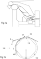
- the sleeve roll belts are preferably non-grooved belts; hence, wear of a sleeve roll belt may be hard to notice without belt wear indicators 20. Furthermore, as shown in Fig. 1a , a sleeve roll belt has typically a difficult accessibility. Thus, the belt wear indicators can be particularly advantageous for sleeve roll belts.
- the sleeve roll 100 having the belt according to this specification can be located in the forming section for improving water removal therein.
- Fig 1b illustrates an example of a sleeve roll.
- the sleeve roll 100 equipped with the belt 1 can be used for dewatering a fiber web 6 on a wire 5.
- the belt 1 may be arranged on a sleeve roll 100.
- the sleeve roll 100 can comprise a support shaft 102.
- the belt 1 can be located around an outer surface of the sleeve roll 100. Thus, the belt 1 can be led to circle around the support shaft 102.
- the belt 1 may be arranged in connection with the sleeve roll 100 in such a way that its outer surface 11 faces the fiber web 6 and its inner surface 10 faces the sleeve roll 100.
- the sleeve roll 100 can be encircled by the belt 1 having the shape of a loop.
- the sleeve roll 100 can comprise support elements located at a distance from each other on the support shaft 102.
- the belt 1, which can circle around the outer surface of the sleeve roll, can be supported by the support elements.
- the sleeve roll 100 can further comprise a curve element 110.
- the belt typically runs through the dewatering zone on the curve element.
- the curve element 110 can cause increased forces which stretch the belt on the curve element 110.
- the curve element 110 may be movable, i.e., a radius of curvature of the belt on the on the surface of the curve element 110 can be controlled by moving the curve element 110 towards the center of the sleeve roll or outward from the outer surface of the sleeve roll.
- stretching of the belt 1 may vary from a normal rate to a very high rate.
- a circumference of the belt may be increased and decreased during operating hours of the belt due to the movable curve element 110. Therefore, the belt may have high elasticity in order to be able to handle the stretching caused by the curve element 110 of the sleeve roll. Further, the belt may have good strength properties so that it does not break easily.
- the belt 1 may be led to circle around the stationary support shaft 102. Further, wire(s) 5 can be led via the curvilinear dewatering zone C1, C2, which dewatering zone can be supported by the belt 1.
- the sleeve roll 100 can comprise at least one curvilinear dewatering zone C1, C2 comprising typically at least two partial curves C1, C2 such that the radius of curvature of a first partial curve C1 may be greater than the radius of curvature of a second partial curve C2 following the first partial curve in the travel direction MD of the belt. This can improve the water removal from the fibre web.
- the curvilinear dewatering zone C1, C2 may be formed by the curve element 110 of the sleeve roll 100.
- the degree of curvature of the curve element 110 can increase in the travel direction of the belt 1 such that increasing dewatering pressure is applied to the fibre web 6 travelling e.g. between wires on said at least one curvilinear dewatering zone C1, C2 on the curve element 110.
- the curvilinear dewatering zone C1, C2 on the curve element 110 may contain several curves such that the radius of curvatures preferably decreases in the running direction of the wires. This can improve the water removal from the fibre web.
- the curve element 110 may be moved between two or more than two positions. Therefore, the curve element 110 may be used for controlling the radius of curvature of the belt 1 on the curve element 110.
- the first position of the curve element 110 may form a first surface on the curve element.
- the first surface may have the same radius of curvature as the surface near the curve element.
- an outer surface of the curve element may be moved outward.
- the second position of the curve element 110 may form a second surface on the curve element.
- the second surface may have decreased radius of curvature, if compared to surfaces near the curve element.
- the belt 1 may need to stretch due to the curve element 110. Further, if the curve element 100 is movable, the belt 1 may need to return to its original shape when the curve element is moved back to the first/retracted position. Thus, the belt 1 may need to have good elasticity as well as suitable strength properties.
- the sleeve roll 100 can further comprise oil lubricant between the inner surface 10 of the belt 1 and the outer surface of the sleeve roll 100.
- the inner surface 10 of the belt 1 can slide against the outer surface of the sleeve roll 100.
- a fibre web 6 to be treated can be led to the belt 1, typically supported by one or more than one fabric, such as a wire 5.
- the belt according to this specification can be arranged to be a sleeve roll belt.
- the belt according to this specification may be arranged to be a shoe press belt, or a roll cover of a calender roll.
- the belt can have an inner surface 10, and an outer surface 11.
- the belt may comprise a reinforcing structure 31, 32.
- the belt can form, at least in operation, a closed loop, i.e., the belt 1 can be shaped like an endless loop.
- the belt 1 can have a length, a circumference, and a thickness.
- the thickness is the smallest dimension.
- the circumference and the length can be selected for adapting the belt to a sleeve roll 100, or to a shoe press, or to a calender roll.
- the circumference of the belt 1 is determined to be such that the inner diameter of the belt 1, when in operation, will be suitable for the purpose.
- the belt 1 can be an impermeable belt. Thus, it is possible to use e.g. an oil layer on the inner surface 10 of the belt without affecting to the outer surface 11 of the belt.
- the term "elasticity” refers to an ability of the belt to return to its original shape when a force is removed.
- Elasticity percentages (%) are values stating how much the belt can stretch elastically.
- the belt may be configured to stretch elastically equal to or more than 1.5% in the travel direction of the belt so that it will return in its original length after the force stretching the belt has been removed.
- the belt can be configured to stretch elastically in a range between 1.5% and 5.0%, more preferably from 2.0% to 4.0%, in the travel direction of the belt so that it will return in its original length after the force stretching the belt has been removed.
- the belt may have good stretchability and elasticity, at least in the travel direction of the belt.
- the belt may not be easily damaged.
- the belt 1 may further be bendable, i.e., the belt can be capable of being bent at least to a predetermined radius of curvature without breaking.
- the length of the belt in the cross direction is determined according to the machine width and may be, for example, in a range between 1.5 m and 13 m.
- the circumference of the belt 1, that is the length of one rotation, is determined to be such that the inner diameter of the belt 1, when in operation, will be suitable for the use. Circumferences of sleeve roll belts, shoe press belts, and calender rolls may differ. An inner diameter of the belt may be in a range between 700 mm and 2000 mm.
- the belt can have outer edges 27 (see Fig. 3b ), which are not typically in contact with a fiber web or a fabric.
- the outer edges 27 may have a length from 200 mm to 400 mm, preferably in a range between 250 mm and 350 mm.
- the thickness 1a of the belt can be at least 1.5 mm, more preferably at least 2 mm, and most preferably equal to or more than 3 mm.
- suitable strength as well as e.g. arrange a reinforcing structure, such as yarns, into the belt.
- the thickness 1a of the belt can be equal or less than 10 mm, more preferably equal to or less than 7 mm, and most preferably equal to or less than 4 mm, for example in a range of 2.5 mm - 5 mm. Said thickness together with materials of the belt can provide good strength properties for the belt, particularly for sleeve roll belts and shoe press belts. When it comes to a roll cover of a calender roll, the thickness can be up to 40 mm, depending on its operation conditions.
- the belt 1 has a body 14.
- the body can comprise or be made of a body material.
- the belt 1 comprises an elastic body which has a capacity to reassume its initial shape after being compressed.
- the belt 1 can comprise an elastic body in order to have a good elasticity.
- the belt 1 can be made of materials, which are suitable for fiber web machines, which do not harm a wire, a felt, or the fiber web, and which have suitable stretching and strength properties.
- the body can comprise or consist of polymer(s).
- the body 14 may comprise or consist of elastomer material.
- the belt 1 may comprise an elastomer material as its main raw material.
- the body 14 may comprise polyurethane.
- the body 14 may contain primarily polyurethane, such as at least 50 wt.-% polyurethane, calculated from the total weight of the belt.
- Polyurethane can improve the properties of the belt, such as elasticity and bendability, and be particularly suitable for use in combination with fabrics 5 and the fiber web 6.
- the polyurethane can be used to obtain good strength and elasticity properties; hence, the belt may be able to stretch and bend during operating hours without breaking.
- the belt may comprise equal to or less than 99.9 wt.-%, more preferably equal to or less than 97 wt.-%, or equal to or less than 95 wt.-% polyurethane, calculated from the total weight of the belt.
- the reinforcing structure 31, 32 can comprise other material(s). Methods for manufacturing polyurethane are known to a person skilled in the art. The manufacturing process of polyurethane may be based on a method of prior art.
- the body of the belt may have layer(s) composed of polyurethane having a specific composition and hardness, and having good physical properties of crack resistance, abrasion resistance, and bending fatigue resistance.
- the belt may comprise a reinforcing structure 30, 31, 32.
- the reinforcing structure 30 can be a support structure supporting the body 14.
- the elasticity of the belt may need to be substantially high, hence, the reinforcing structure 30 should not decrease the elasticity of the belt too much.
- the reinforcing structure 30, 31, 32 may comprise yarns.
- the term “yarn” refers to a long structure, which has relatively small cross section.
- the yarn can be composed of fibers and/or filaments, with or without twist.
- the term “filament” refers to a fiber of great length.
- the yarn can be multiple plied yarn.
- the yarn can be based on synthetic polymer(s).
- the belt may have several yarns arranged in at least two directions, i.e., the first direction D1 and the second direction D2.
- the first direction D1 can be parallel or substantially parallel to a travel direction MD of the belt.
- the second direction D2 can be parallel or substantially parallel to an axis of rotation of the belt.
- Adjacent yarns in each layer may be either in contact with or bonded to each other, or they may be spaced from each other.
- the yarns in different layers 31, 32 may be either in contact with or bonded to the yarns of the next layer, or they may be spaced from each other.
- the reinforcing yarn layers 31, 32 on top of each other are separated from each other.
- the yarn layers do not have to be fastened to each other or bound to each other in any way.
- strength properties of the reinforcing structure may be improved.
- the yarns may be embedded in the elastic body. Thus, the yarns may be fully surrounded by the material of the body.
- the yarns may comprise synthetic fibers having high strength, high modulus, and high elastic modulus.
- the yarns can comprise or consist of at least one of: polyamide (PA), e.g. nylon, polypropylene (PP), polyethylene (PE), rayon, viscose, polyester such as polyethylene terephthalate (PET), polyvinyl alcohol (PVA), polyaramide, polyphenylene sulfide (PPS), liquid crystal plastic (LCP), polyimide, and polyether ether ketone (PEEK).
- PA polyamide
- PP polypropylene
- PE polyethylene
- rayon rayon
- viscose polyester
- polyester such as polyethylene terephthalate (PET), polyvinyl alcohol (PVA), polyaramide, polyphenylene sulfide (PPS), liquid crystal plastic (LCP), polyimide, and polyether ether ketone (PEEK).
- PA polyamide
- PP polypropylene
- PE polyethylene
- rayon rayon
- the belt can have a non-grooved outer surface 11.
- non-grooved surface refers to such an outer surface of the belt, in which deviations having a depth of more than 0.1 mm form equal to or less than 10% of said surface.
- the outer surface 11 of the belt does not comprise many parallel grooves.
- the belt may have a smooth outer surface.
- outer surface of a sleeve roll belt is preferably smooth or substantially smooth.
- the belt 1 having the smooth outer surface may not have grooves, nor patterning, having a depth of more than 0.1 mm, excluding the belt wear indicators.
- the outer surface 11 of the belt may comprise a slight patterning, i.e. so-called buffing.
- the depth of the buffing on the outer surface 11 of the belt 1 may be, for example, 0 to 50 ⁇ m, or 3 to 30 ⁇ m.
- a suitable roughness of the outer surface of the belt may have advantageous effects on its action together with a fiber web machine fabric.
- the belt 1 comprises one or more belt wear indicators 20. Some examples of the belt wear indicators are illustrated in Figs 2b - 4f .
- the belt wear indicator 20 may be used for warning a user when the belt has been worn so that the belt may soon be broken. Thanks to the belt wear indicators, wear of the belt can be easily checked during shut downs, and the belt may be replaced with a new one controllable during a determined shut down.
- the belt wear indicator 20 can comprise or consist of a recess 24.
- a worn of the belt can be documented, for example, by a camera, and/or measured, for example, as a depth, width and/or length of the belt wear indicator 20.
- the belt wear indicator can have a form of a (blind) hole.
- the belt wear indicator 20 can comprise or consist of a recess 24 without a fill, or the belt wear indicator 20 can comprise or consist of a recess 24 having a fill 25. Therefore, the recess 24 may be at least partially filled with the fill 25.
- the fill can comprise or consist of a paint.
- the recess is not totally filled with the fill but there is only a layer of a paint on at least some surfaces of the recess.
- the recess may have the paint on all, or substantially all, surfaces of the recess.
- Color(s) of the belt wear indicator can differ from color(s) of the belt.
- the belt wear indicator 20 may have a color that is visually perceptible from the color of the belt.
- the fill 25, such as a paint preferably has a color that is visually perceptible from the color of the belt.
- the recess 24 may be painted for improved visibility.
- the belt wear indicator can comprise a UV detectable component, such as a UV detectable paint.
- the belt wear indicator can comprise a UV detectable paint.
- the UV detectable paint may have the same color as the belt, or the color of the UV detectable paint can be visually perceptible from the color of the belt.
- the belt wear indicator has the UV detectable component, such as a paint
- the belt wear indicator can have the same color as the belt and still be easily detected from the outer surface of the belt during shutdowns.
- a color of the belt wear indicator 20 is the same as the color of the belt. If the color of the belt wear indicator is the same as the color of the belt, and the belt wear indicator does not have the UV detectable component, locations of the belt wear indicators may be difficult to see. However, the worn of the belt may still be documented by a camera, and/or measured, for example, as a depth of the belt wear indicator 20.
- the fill can be designed to wear down simultaneously with the belt.
- the fill may be, for example, a paint in the recess covering at least some surfaces of the recess. This embodiment may be particularly cost-efficient solution able to greatly improve easiness of visual inspection. Further, thanks to the fill, such as the paint, the worn of the belt may be easily measured and/or documented e.g. by a camera.
- the belt After installation, belts can typically be visually checked only on minor areas of the belt.
- the difficulties in accessibility are mainly due to several frames, guard type sheeting and dewatering elements surrounding the roll, as shown in Fig. 1a .
- the belt In order to obtain an easy visual inspection, the belt preferably has several belt wear indicators spaced from each other and positioned around the whole circumference of the belt as illustrated in Fig. 3b . Therefore, no matter in what position the roll is when being stopped for maintenance, at least one of the wear indicators can be observed or accessed.
- the belt may comprise equal to or more than 1 belt wear indicator, preferably at least 10 belt wear indicators.
- total amount of the belt wear indicators may be at least 2 pcs/belt and not more than 2000 pcs/belt, preferably at least 30 pcs/belt, more preferably at least 40 pcs/belt and not more than 500 pcs/belt. Therefore, it is possible to provide, anytime, at any position of the belt, at least one belt wear indicator 20 that can be seen at an installation location at a shut-down position of the belt. Further, it is possible to obtain cost-effective solution which does not have too much effect on properties of the belt. This kind of wear indicators are easy and fast to manufacture without any installation of external sensors or alike. Further, in order not to affect strength properties of the belt, it may be advantageous for not having too many wear indicators.
- the belt wear indicators can be spaced apart from each other.
- the belt wear indicator 20 may have, e.g. a rectangular shape, a cylindrical shape, such as a plug shape, a conical shape, a frustoconical shape, or a strip shape, such as a groove shape.
- the belt wear indicator 20 has a shape of a cylindrical plug.
- the shape of a cylindrical plug may be advantageous for durability of the belt, especially with deep recess.
- the belt wear indicator 20 has a shape of a groove having a length of at least 10 mm.
- the shape of groove(s) can provide a technical effect of improving easiness of detect an exact wear rate of the belt.
- easiness of indicate exact position of local wear in CD direction can be improved.
- grooves oriented in MD direction can help to spot local MD discontinuations, such as for example problems with support yarns.
- the belt wear indicator 20 has a shape of several parallel grooves each having a length of at least 1 mm, preferably at least 10 mm, and preferably less than 100 mm. This kind of shape comprising several parallel grooves may be used for revealing matrix like information of the belt wear. A distance between adjacent grooves forming the shape may be, for example, from 5 mm to 50 mm.
- the belt wear indicator 20 may have a circular cross-section as shown in Fig. 2b , or a strip-like cross section as shown in Fig. 3a , or any other form.
- the belt wear indicator 20 may have, for example, at least one of the following cross-sections: circle, ellipse, square, rectangle, triangle, pentagon, and polygon.
- the belt wear indicator 20 may have a suitable width 22 and length 21 to be easily measured. Further, the belt wear indicator 20 can extend to a suitable depth 23 in order to be able to show wear level of the belt.
- all, or at least substantially all, belt wear indicators have a width 22 from 1 mm to 10 mm.
- the belt wear indicator 20 may have a width 22 from 1 mm to 10 mm, preferably from 2 mm to 6 mm. This kind of belt wear indicators can be used to determinate a wear rate of the belt without affecting the operational performance of the belt. Therefore, the belt wear indicator 20 can have a width 22 of equal to or more than 1 mm, preferably equal to or more than 1.5 mm, and most preferably equal to or more than 2 mm. Further, the belt wear indicator 20 may have the width 22 of equal to or less than 10 mm, preferably equal to or less than 8 mm, more preferably equal to or less than 7 mm, and most preferably equal to or less than 6 mm. Width of the belt wear indicator can be used to code and/or mark different depths of indicators adjacent to each other. The width 22 can be measured as the greatest width 22 of the belt wear indicator 20, determined from a new belt.
- the belt wear indicator can have a length 21 of equal to or more than 1 mm, preferably equal to or more than 2 mm, and most preferably equal to or more than 3 mm. Further, the belt wear indicator 20 may have the length 22 of equal to or less than 100 mm, preferably equal to or less than 40 mm, more preferably equal to or less than 20 mm, and most preferably equal to or less than 10 mm, such as equal to or less than 6 mm.
- the length 21 can be measured as the greatest measure of the belt wear indicator 20 along the outer surface of the belt, determined from a new belt. Length of the belt wear indicator can be used to code and/or mark different depths of indicators adjacent to each other. This kind of belt wear indicators may be used to determinate a wear rate of the belt without affecting the operational performance of the belt.
- the depth 23 of the belt wear indicator 20 can be determined in the depth direction of the belt (from a new belt), at the location of the belt wear indicator.
- the depth 23 of the belt wear indicator 20 typically decreases when the belt wears.
- the belt wear indicator 20 can be arranged to extend a depth 23 of equal to or less than 6 mm, determined in the depth direction of the belt, before the belt has worn.
- the belt wear indicator 20 can be arranged to extend, for example, to a depth 23 from 0.1 mm to 4.2 mm determined in the depth direction from the outer surface of the belt, before the belt has worn.
- the belt wear indicator 20 extends to a depth 23 of at least 0.3 mm, more preferably to a depth of at least 0.5 mm, determined in the depth direction from the outer surface of the belt, before the belt has worn.
- the belt can have a safe distance between the belt wear indicator(s) and the reinforcing structure (such as yarns).
- a distance between the belt wear indicator and the outermost surface of the reinforcing structure can be at least 0.01 mm, preferably at least 0.05 mm, more preferably at least 0.08 mm, and most preferably at least 0.1 mm, determined from the bottom of the belt wear indicator to the outer surface of the reinforcing structure in the depth direction of the belt.
- the belt wear indicator 20 may be able to warn a user when the belt has been worn, before damaging yarns.
- a distance between the belt wear indicator and the outermost surface of the reinforcing structure can be equal to or less than 1.5 mm, preferably equal to or less than 1 mm, more preferably equal to or less than 0.8 mm and most preferably equal to or less than 0.5 mm, determined from the bottom of the belt wear indicator to the outer surface of the reinforcing structure in the depth direction of the belt.
- the belt wear indicator 20 may be able to warn a user at any time before the belt is too worn to be safe.
- the shape of the belt wear indicator 20 may taper from the top of the indicator to the bottom of the indicator.
- the belt wear indicator 20 may have a tapered shape which tapers in the depth direction from the outer surface of the belt to the bottom of the belt wear indicator 20. Therefore, a length 21 and/or a width 22 of the belt wear indicator 20 can decrease along with the depth 23 of the belt wear indicator 20.
- the belt wear indicator 20 may get shorter and/or thinner. This may improve easiness of detecting wear of the belt as the wear level may be measured from the outer surface of the belt as the length 21 and/or the width 22 of the belt wear indicator 20.
- the belt wear indicators may cover equal to or less than 10% of total outer surface area of the belt.
- the belt wear indicators cover equal to or less than 3%, preferably equal to or less than 2%, more preferably equal to or less than 1%, and most preferably equal to or less than 0.5% from the total outer surface area of the belt.
- wear of the belt may be easily determined cost-efficiently without affecting the operational performance of the belt.
- a distance between two nearest belt wear indicators may not be more than 50 cm, preferably not more than 40 cm, and most preferably not more than 30 cm, determined in the machine direction of the belt.
- a distance 28 between two adjacent belt wear indicators may be at least 10 mm, such as from 10 mm to 300 mm, preferably from 30 mm to 200 mm, and most preferably from 50 mm to 100 mm.
- the belt wear indicators can be diagonally positioned in order to have easy visual inspection.
- easiness of checking wear level of the belt may be improved, at any position of the belt, despite of the difficult location of e.g. a sleeve roll.
- the spirally positioned belt wear indicators give an advantage to see differences in wear within areas with forming fabric vs. areas without forming fabric.
- different width of forming fabrics can be used so that some belt wear indicators are always positioned under the forming fabric, but the wear of the belt may be measured as near of the end of the roll as possible.
- a circumference repetition 29 of wear indicators may depend on a circumference of a belt. Circumference repetition 29 of wear indicators, determined from the first belt wear indicator to the last belt wear indicator in MD, may be, for example, from 400 mm to 1300 mm, for example from 500 mm to 1000 mm.
- the belt wear indicators are preferred to distribute around the entire circumference, so that whenever the shutdown takes place the wear of the belt can be observed at that shutdown position. Otherwise, it is not easy to turn the rolls in order to see the wear indicator(s).
- the belt wear indicators may be positioned within a location area(s) 26 of the belt wear indicators.
- the belt 1 may have a first location area of the belt wear indicators, the length of the first location area extending from a first end 2 of the belt towards a central of the belt.
- the belt 1 may have a second location area of the belt wear indicators, the length of the second location area extending from a second end 3 of the belt towards a center of the belt.
- locations of belt wear indicators do not exceed the first location area 26 and/or a second location area of belt wear indicators.
- a length of the first and/or second location area(s) of belt wear indicators may be, for example, in a range between 20 cm and 1.5 m, preferably in a range between 30 cm and 1.2 m, and most preferably at least 40 cm, determined from the end(s) 2, 3 of the belt, excluding the outer edge area 27 of the belt, towards the center of the belt.
- a middle area of the outer surface of the belt is free from the belt wear indicators. This may reduce manufacturing costs of the belt. Further, belt wear indicators may not be needed in the middle of the belt as it is typically easier to determine wear rate of the belt from side areas of the belt.
- the belt should wear evenly. However, in some cases the center of the belt may worn faster or slower than other parts of the belt.
- the belt comprises wear indicators also in the middle area of the outer surface of the belt. In this embodiment, it is possible to determine whether the belt has worn evenly through the whole outer surface area of the belt. Therefore, in an embodiment, at least one belt wear indicator 20 may be located in the center, or substantially center, of the belt. Therefore, after replacing the belt, the wear level of the belt may be examined through the whole outer surface are of the belt.
- the belt wear indicator 20 may form an angle ⁇ between 70 and 110 degrees, preferably between 80 and 100 degrees, relative to the outer surface of the of the belt at the location of the belt wear indicator 20. Said angle ⁇ may improve the easiness of the manufacturing process. Further, belt wear indicators having said angle ⁇ may not substantially affect to properties of the belt. Still further, thanks to said angles, a user of the belt wear indicator 20 may interpret the wear of the belt easier, compared to other angles.
- the belt may be manufactured by methods known by a person skilled in the art.
- the belt may be manufactured, e.g., by
- a method for manufacturing a belt for a fiber web machine may comprise the following steps:
- the belt wear indicator 20, and particularly the recess of the belt wear indicator may be formed, for example, by a micro drilling technique, or by laser or melting tools.
- the grooved type of indicator may be done, for example, with a grooving tool, such as a fixed diameter round blade. Further, the fill, if used, may be added, for example, by applying a paint.
- the belt can be intended to be installed on a sleeve roll, or a shoe press, or a calender roll of a fiber web machine.
- the belt may further comprise e.g. plurality of attaching points 60 of the belt for an installation of the belt.
- the belt wear indicators worn of the belt can be easily determined. Further, it was noted during experimental tests that the belt wear indicators according to this specification did not have effect on other properties of the belt, such as strength properties of the belt. Furthermore, the belt wear indicators did not cause markings onto a surface of the fiber web.
Landscapes
- Paper (AREA)
- Preliminary Treatment Of Fibers (AREA)
- Belt Conveyors (AREA)
Abstract
Description
- This invention relates to a belt for a fiber web machine. The invention further relates to a use of belt wear indicators in a belt of a fiber web machine.
- Fiber web machines, such as paper machines, as well as board, pulp, and tissue machines, are typically equipped with a forming section, a press section, and a drying section. In paper, pulp and board making, it is an issue how to increase the dewatering amount from wet fiber web in order to improve a production efficiency without decreasing the physical properties of a fiber web.
- Nowadays, these machines typically have felts and wires to support water removal or conveying of the fiber web. Furthermore, paper machines may have a finishing section to improve the final product properties, such as calender machine(s) for improving smoothness of the dried fiber web.
- It is well known that fiber web machines comprise many kinds of rolls located in different sections with distinguishing functions. For instance, a sleeve roll can be used in the forming section to improve the removal of free water from the wet fiber material. A shoe press can be used, for example, in press sections to improve the removal of residual water in the fiber web therein. Both sleeve roll and shoe press roll need belts to be able to run properly.
-
WO200371030 - The present invention relates to a belt for a fiber web machine. One object of the present invention is to provide an improved belt for a fiber web machine.
- Aspects of the invention are characterized by what is stated in the independent claims. Various embodiments of the invention are disclosed in the dependent claims.
- A fiber web machine may be a paper machine, or it may be a board, pulp, or tissue machine.
- A fiber web machine may comprise a sleeve roll. The sleeve roll is typically located at a wire section of a fiber web machine. Thanks to the sleeve roll, water removal of the wire section can be improved. Advantageously, the belt according to this specification is a sleeve roll belt.
- Further, a fiber web machine may comprise a shoe press. The shoe press is typically located at a press section of a fiber web machine. Thanks to the shoe press, water removal of the press section can be improved. In an embodiment, the belt according to this specification is a shoe press belt.
- Further, a fiber web machine may comprise at least one calender. Thanks to the calender, smoothness of a dried fiber web may be improved. In an embodiment, the belt according to this specification is a roll cover of a calender roll.
- Therefore, the belt may be a sleeve roll belt, or a shoe press belt, or a roll cover.
- The belt according to this specification comprises a belt wear indicator. The belt wear indicator is advantageously used for a belt having a non-grooved outer surface. A sleeve roll, as well as a calender roll, preferably has a belt having said non-grooved surface. Thus, advantageously, the belt having the belt wear indicator is the sleeve roll belt or the belt cover of the calender roll.
- Determining a wear level of a sleeve roll belt has conventionally been particularly challenging and, hence, belt wear indicators may be particularly useful for sleeve roll belts. Thus, most advantageously, the belt having the belt wear indicator is the sleeve roll belt.
- The belt according to this specification has an inner surface and an outer surface. The belt can comprise a body comprising a body material. Further, the belt can comprise a reinforcing structure, which may be, e.g., embedded into the body. In use, the belt typically forms a closed loop. The belt can be an impermeable belt.
- The outer surface of the belt comprises a belt wear indicator having a length and a width. The belt wear indicator can comprise a recess extending to a predetermined depth, determined from the outer surface of the belt in a depth direction of the belt.
- The belt can have a non-grooved outer surface, wherein deviations having a depth of more than 0.1 mm form equal to or less than 10%, preferably equal to or less than 3%, from a surface area of the outer surface of the belt. In an embodiment, the belt does not have any deviations excluding the belt wear indicators, i.e., the belt can have a smooth, or at least substantially smooth outer surface.
- The belt wear indicator can comprise at least one visually distinctive material being visually perceptible from color of the belt. For example, the belt wear indicator may comprise a paint in the recess.
- Alternatively or in addition to the visually distinctive material, the belt wear indicator can comprise at least one UV detective material. For example, the belt wear indicator can comprise a UV detective paint in the recess.
- The belt comprises at least 1 belt wear indicator. Preferably, the belt comprises at least 2 belt wear indicators. Further, the belt may comprise equal to or less than 2000 belt wear indicators.
- As discussed, the belt wear indicator extends to a depth, which depth can be determined from the outer surface of the belt to the bottom of the belt wear indicator in the depth direction of the belt. At least the depth of the belt wear indicator can decrease as the belt wear. In an embodiment, the length of the belt wear indicator decreases as the belt wears. Alternatively or in addition, the width of the belt wear indicator can decrease as the belt wears. In an embodiment, the belt wear indicator tapers in the depth direction from a top of the belt wear indicator to the bottom of the belt wear indicator.
- The width of the belt wear indicator can be in a range between 1 mm and 10 mm, measured from a new belt before the belt has worn. Thus, the belt wear indicator can be easily seen.
- The belt can be arranged to have a safe distance between the belt wear indicator and a reinforcement structure of the belt, such as yarns, in order to protect the reinforcement structure of the belt. Thus, the belt wear indicator preferably extends to a depth that is at least 0.01 mm smaller, preferably at least 0.1 mm smaller, than a depth of an outermost surface of a reinforcement structure of the belt, determined in the depth direction of the belt.
- Therefore, a distance between the bottom of the belt wear indicator and the outer surface of the reinforcing structure can be at least 0.01 mm, preferably at least 0.1 mm, determined in the depth direction of the belt from the bottom of the belt wear indicator to the outermost surface of the reinforcement structure. Thus, the belt wear indicator can be used to protect the reinforcement structure of the belt.
- For determining a wear rate of a belt at any time before the belt is too worn to be safe, the distance between the belt wear indicator and the reinforcing structure of the belt can be equal to or less than 1.5 mm, preferably equal to or less than 1 mm, determined in the depth direction of the belt from the bottom of the belt wear indicator to the outermost surface of the reinforcing structure.
- The belt wear indicator can have, for example, a shape of a cylindrical plug, or a shape of one or more grooves.
- All belt wear indicators of the belt can cover less than 10% of the outer surface area of the belt. Preferably, the belt wear indicators cover equal to or less than 3%, more preferably equal to or less than 1%, and most preferably equal to or less than 0.5% of the outer surface area of the belt, determined as a total outer surface area of the belt wear indicators.
- The novel solution has many advantages. As machine components of fiber web machines are typically located in a compact manner, the inspection or maintenance has conventionally been challenging due to a limited space. The wear of the belt should be detected early enough to have time to change the belt in a controlled way during a shut down. In order to save costs, belts are often changed as late as possible. However, the belt must be replaced with a new one before it is broken.
- Belts wear over time so that belt inspection and maintenance are required to be conducted in time in order to avoid operational failures.
- Thanks to the belt wear indicators which can cover very small but well-arranged area of the belt, it is possible to see wear rate of the belt all time, regardless of current wear rate. Furthermore, the low coverage of wear indicators on the outer surface of the belt will not affect the belt's operational performance or the physical characteristics of the fiber web.
- Conventionally, it has been challenging and expensive to determine a wear rate of a belt. For example,
WO200371030 - Thanks to the belt according to this specification, an exact wear rate of a belt can be determined cost efficiently.
- The novel belt wear indicator can indicate when the belt has been worn such that the belt may break in use, without substantially affecting other properties of the belt. Further, the novel belt wear indicator can indicate how much the belt has been worn at any specific moment. Thanks to the novel belt, it is possible to indicate a wear level of a non-grooved belt easily, without using difficult or non-reliable measuring devices. Further, the wear rate of a belt can be detected early enough to have time to change the belt in a controlled way, for example, during a selected shut down period.
- In the following, the invention will be illustrated by drawings in which
- Fig. 1a
- illustrates an example location of a sleeve roll,
- Fig. 1b
- illustrates an example of a sleeve roll,
- Fig. 2a
- illustrates an example of a belt,
- Figs 2b-3a
- illustrate some example structures for a belt,
- Fig. 3b
- illustrates example locations for belt wear indicators, and
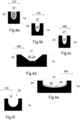
- Figs 4a-4f
- illustrate some example cross sections of belt wear indicators.
- The figures are illustrations which may not be in scale. Similar parts are indicated in the figures by the same reference numbers.
- The solution is described in the following in more detail with reference to some embodiments, which shall not be regarded as limiting.
- In this specification, references are made to the figures with the following numerals and denotations:
- 1
- belt,
- 1a
- thickness of a body of the belt,
- 2
- first end of the belt,
- 3
- second end of the belt,
- 5
- fiber web machine fabric, e.g. a wire or a felt,
- 6
- fiber web,
- 10
- inner surface of the belt,
- 11
- outer surface of the belt,
- 14
- body of the belt,
- 20
- belt wear indicator,
- 21
- length of the belt wear indicator,
- 22
- width of the belt wear indicator,
- 23
- depth of the belt wear indicator,
- 24
- recess of the belt wear indicator,
- 25
- fill of the belt wear indicator, such as a paint in a recess,
- 26
- length of a location area of belt wear indicators,
- 27
- outer edge area of the belt,
- 28
- distance between adjacent belt wear indicators,
- 29
- circumference repetition of wear indicators, i.e., distance between a first wear indicator and a last wear indicator, determined in MD,
- 30
- reinforcing structure,
- 31
- first yarn layer of the reinforcing structure,
- 32
- second yarn layer of the reinforcing structure,
- 60
- attaching point of the belt,
- 100
- sleeve roll,
- 102
- support shaft of the sleeve roll,
- 110
- curve element of the sleeve roll,
- α
- angle between the belt wear indicator and an outer surface of the belt,
- D1
- first direction of the belt,
- D2
- second direction of the belt,
- MD
- travel direction of the belt,
- CD
- cross direction of the belt,
- C1
- first curve of the sleeve roll, and
- C2
- second curve of the sleeve roll.
- The embodiments and examples recited in the claims and in the specification are mutually freely combinable unless otherwise explicitly stated.
- In this specification, the term "comprising" may be used as an open term, but it also comprises the closed term "consisting of". Thus, unless otherwise indicated, the word "comprising" can be read as "comprising or consisting of".
- For the purpose of the present description and the claims, unless otherwise indicated, all ranges include any combination of the maximum and minimum points disclosed, and include any intermediate ranges therein, which may or may not be specifically enumerated herein.
- The term "thickness" refers to a depth direction of the belt.
- In this application, the terms "travel direction" MD and "cross direction" CD are used. The travel direction MD refers to the direction of rotation of the belt in use. The cross-direction CD refers to the longitudinal direction, typically transverse to the travel direction MD of the
belt 1. In use, the cross-direction is substantially parallel to the axis of rotation of the belt. - In this application, the term "substantially parallel" means that one direction does not deviate from said substantially parallel direction by more than 10 degrees, most preferably not by more than 3 degrees. Thus, e.g. "substantially parallel to the travel direction" means, in this application, that a direction does not deviate from said travel direction by more than 10 degrees, and preferably not by more than 3 degrees.
- The term "non-grooved surface" refers to such an outer surface of the belt, in which deviations having a depth of more than 0.1 mm form equal to or less than 10% of said surface, preferably the surface is plane or at least mainly plane. This specification does not relate to belts having a grooved surface. Conventionally, grooves have been distributed all over the outer surface of belts to meet certain operation requirements, for instance, to remove water in 2 directions with respect to the belt. Surprisingly, some belts having a non-grooved outer surface, such as sleeve roll belts, have shown many advantages over belts having said grooved surface. Thus, the novel belt has the non-grooved surface, in which deviations having a depth of more than 0.1 mm form equal to or less than 10% of said surface.
- A fiber web machine according to this specification may comprise at least one of: a sleeve roll, a shoe press, and a calender.
- A fiber web machine may comprise a calender.
- The function of calenders is typically to improve a smoothness of a fiber web to be treated. A calender has typically at least two rolls that close under pressure to compress and smooth fiber webs.
- The belt can be (arranged) in connection with a calender roll in such a way that, in use, the
belt 1 can run through a press zone formed between calender rolls. - A fiber web machine may comprise a shoe press.
- The shoe press equipped with the
belt 1 can be used for dewatering a fiber web. The shoe press typically comprises a counter roll and a press shoe, a press zone being formed between them. Thus, an extended press zone, i.e. a so-called long nip, is formed between the press shoe and the counter roll. The function of the shoe press is typically to remove water from the fiber web. - The belt is or can be arranged in connection with the shoe press in such a way that, in operation, the belt runs through the press zone between a counter roll and the press shoe.
- Typically, the press shoe and the counter roll are pressed against each other in the press zone in such a way that the shoe press belt, at least one paper machine fabric and the fiber web to be dewatered, all run in the nip between the press shoe and the counter roll, are compressed.
- A fiber web machine may comprise a sleeve roll. The belt may be a sleeve roll belt.
- The sleeve roll belts are preferably non-grooved belts; hence, wear of a sleeve roll belt may be hard to notice without
belt wear indicators 20. Furthermore, as shown inFig. 1a , a sleeve roll belt has typically a difficult accessibility. Thus, the belt wear indicators can be particularly advantageous for sleeve roll belts. Thesleeve roll 100 having the belt according to this specification can be located in the forming section for improving water removal therein. -
Fig 1b illustrates an example of a sleeve roll. Thesleeve roll 100 equipped with thebelt 1 can be used for dewatering a fiber web 6 on a wire 5. Thebelt 1 may be arranged on asleeve roll 100. - The
sleeve roll 100 can comprise asupport shaft 102. Thebelt 1 can be located around an outer surface of thesleeve roll 100. Thus, thebelt 1 can be led to circle around thesupport shaft 102. - The
belt 1 may be arranged in connection with thesleeve roll 100 in such a way that itsouter surface 11 faces the fiber web 6 and itsinner surface 10 faces thesleeve roll 100. Thus, thesleeve roll 100 can be encircled by thebelt 1 having the shape of a loop. - Further, the
sleeve roll 100 can comprise support elements located at a distance from each other on thesupport shaft 102. Thebelt 1, which can circle around the outer surface of the sleeve roll, can be supported by the support elements. - The
sleeve roll 100 can further comprise acurve element 110. In operation, the belt typically runs through the dewatering zone on the curve element. Thecurve element 110 can cause increased forces which stretch the belt on thecurve element 110. Thecurve element 110 may be movable, i.e., a radius of curvature of the belt on the on the surface of thecurve element 110 can be controlled by moving thecurve element 110 towards the center of the sleeve roll or outward from the outer surface of the sleeve roll. Thus, stretching of thebelt 1 may vary from a normal rate to a very high rate. - A circumference of the belt may be increased and decreased during operating hours of the belt due to the
movable curve element 110. Therefore, the belt may have high elasticity in order to be able to handle the stretching caused by thecurve element 110 of the sleeve roll. Further, the belt may have good strength properties so that it does not break easily. - As discussed, the
belt 1 may be led to circle around thestationary support shaft 102. Further, wire(s) 5 can be led via the curvilinear dewatering zone C1, C2, which dewatering zone can be supported by thebelt 1. - The
sleeve roll 100 can comprise at least one curvilinear dewatering zone C1, C2 comprising typically at least two partial curves C1, C2 such that the radius of curvature of a first partial curve C1 may be greater than the radius of curvature of a second partial curve C2 following the first partial curve in the travel direction MD of the belt. This can improve the water removal from the fibre web. - The curvilinear dewatering zone C1, C2 may be formed by the
curve element 110 of thesleeve roll 100. The degree of curvature of thecurve element 110 can increase in the travel direction of thebelt 1 such that increasing dewatering pressure is applied to the fibre web 6 travelling e.g. between wires on said at least one curvilinear dewatering zone C1, C2 on thecurve element 110. The curvilinear dewatering zone C1, C2 on thecurve element 110 may contain several curves such that the radius of curvatures preferably decreases in the running direction of the wires. This can improve the water removal from the fibre web. - The
curve element 110 may be moved between two or more than two positions. Therefore, thecurve element 110 may be used for controlling the radius of curvature of thebelt 1 on thecurve element 110. - The first position of the
curve element 110 may form a first surface on the curve element. The first surface may have the same radius of curvature as the surface near the curve element. - In the second position of the
curve element 110, an outer surface of the curve element may be moved outward. Thus, the second position of thecurve element 110 may form a second surface on the curve element. The second surface may have decreased radius of curvature, if compared to surfaces near the curve element. - In the second position of the
curve element 110, thebelt 1 may need to stretch due to thecurve element 110. Further, if thecurve element 100 is movable, thebelt 1 may need to return to its original shape when the curve element is moved back to the first/retracted position. Thus, thebelt 1 may need to have good elasticity as well as suitable strength properties. - The
sleeve roll 100 can further comprise oil lubricant between theinner surface 10 of thebelt 1 and the outer surface of thesleeve roll 100. Theinner surface 10 of thebelt 1 can slide against the outer surface of thesleeve roll 100. A fibre web 6 to be treated can be led to thebelt 1, typically supported by one or more than one fabric, such as a wire 5. - The belt according to this specification can be arranged to be a sleeve roll belt. Alternatively, the belt according to this specification may be arranged to be a shoe press belt, or a roll cover of a calender roll.
- The belt can have an
inner surface 10, and anouter surface 11. The belt may comprise a reinforcing structure 31, 32. - The belt can form, at least in operation, a closed loop, i.e., the
belt 1 can be shaped like an endless loop. - The
belt 1 can have a length, a circumference, and a thickness. The thickness is the smallest dimension. The circumference and the length can be selected for adapting the belt to asleeve roll 100, or to a shoe press, or to a calender roll. The circumference of thebelt 1 is determined to be such that the inner diameter of thebelt 1, when in operation, will be suitable for the purpose. - The
belt 1 can be an impermeable belt. Thus, it is possible to use e.g. an oil layer on theinner surface 10 of the belt without affecting to theouter surface 11 of the belt. - In this application, the term "elasticity" refers to an ability of the belt to return to its original shape when a force is removed. Elasticity percentages (%) are values stating how much the belt can stretch elastically. The belt may be configured to stretch elastically equal to or more than 1.5% in the travel direction of the belt so that it will return in its original length after the force stretching the belt has been removed. In an embodiment, the belt can be configured to stretch elastically in a range between 1.5% and 5.0%, more preferably from 2.0% to 4.0%, in the travel direction of the belt so that it will return in its original length after the force stretching the belt has been removed.
- Thus, the belt may have good stretchability and elasticity, at least in the travel direction of the belt. Thus, the belt may not be easily damaged. The
belt 1 may further be bendable, i.e., the belt can be capable of being bent at least to a predetermined radius of curvature without breaking. - The length of the belt in the cross direction is determined according to the machine width and may be, for example, in a range between 1.5 m and 13 m.
- The circumference of the
belt 1, that is the length of one rotation, is determined to be such that the inner diameter of thebelt 1, when in operation, will be suitable for the use. Circumferences of sleeve roll belts, shoe press belts, and calender rolls may differ. An inner diameter of the belt may be in a range between 700 mm and 2000 mm. - The belt can have outer edges 27 (see
Fig. 3b ), which are not typically in contact with a fiber web or a fabric. The outer edges 27 may have a length from 200 mm to 400 mm, preferably in a range between 250 mm and 350 mm. - The
thickness 1a of the belt can be at least 1.5 mm, more preferably at least 2 mm, and most preferably equal to or more than 3 mm. Thus, it is possible to obtain suitable strength as well as e.g. arrange a reinforcing structure, such as yarns, into the belt. - The
thickness 1a of the belt can be equal or less than 10 mm, more preferably equal to or less than 7 mm, and most preferably equal to or less than 4 mm, for example in a range of 2.5 mm - 5 mm. Said thickness together with materials of the belt can provide good strength properties for the belt, particularly for sleeve roll belts and shoe press belts. When it comes to a roll cover of a calender roll, the thickness can be up to 40 mm, depending on its operation conditions. - The
belt 1 has abody 14. The body can comprise or be made of a body material. Preferably, thebelt 1 comprises an elastic body which has a capacity to reassume its initial shape after being compressed. Thus, thebelt 1 can comprise an elastic body in order to have a good elasticity. - The
belt 1 can be made of materials, which are suitable for fiber web machines, which do not harm a wire, a felt, or the fiber web, and which have suitable stretching and strength properties. - The body can comprise or consist of polymer(s). The
body 14 may comprise or consist of elastomer material. Thebelt 1 may comprise an elastomer material as its main raw material. - The
body 14 may comprise polyurethane. Thebody 14 may contain primarily polyurethane, such as at least 50 wt.-% polyurethane, calculated from the total weight of the belt. Polyurethane can improve the properties of the belt, such as elasticity and bendability, and be particularly suitable for use in combination with fabrics 5 and the fiber web 6. Thus, the polyurethane can be used to obtain good strength and elasticity properties; hence, the belt may be able to stretch and bend during operating hours without breaking. Furthermore, the belt may comprise equal to or less than 99.9 wt.-%, more preferably equal to or less than 97 wt.-%, or equal to or less than 95 wt.-% polyurethane, calculated from the total weight of the belt. For example the reinforcing structure 31, 32 can comprise other material(s). Methods for manufacturing polyurethane are known to a person skilled in the art. The manufacturing process of polyurethane may be based on a method of prior art. - The body of the belt may have layer(s) composed of polyurethane having a specific composition and hardness, and having good physical properties of crack resistance, abrasion resistance, and bending fatigue resistance.
- The belt may comprise a reinforcing structure 30, 31, 32. The reinforcing structure 30 can be a support structure supporting the
body 14. The elasticity of the belt may need to be substantially high, hence, the reinforcing structure 30 should not decrease the elasticity of the belt too much. - The reinforcing structure 30, 31, 32 may comprise yarns. The term "yarn" refers to a long structure, which has relatively small cross section. The yarn can be composed of fibers and/or filaments, with or without twist. The term "filament" refers to a fiber of great length.
- The yarn can be multiple plied yarn. The yarn can be based on synthetic polymer(s).
- The belt may have several yarns arranged in at least two directions, i.e., the first direction D1 and the second direction D2. The first direction D1 can be parallel or substantially parallel to a travel direction MD of the belt. The second direction D2 can be parallel or substantially parallel to an axis of rotation of the belt.
- Adjacent yarns in each layer may be either in contact with or bonded to each other, or they may be spaced from each other.
- The yarns in different layers 31, 32 may be either in contact with or bonded to the yarns of the next layer, or they may be spaced from each other. Preferably, the reinforcing yarn layers 31, 32 on top of each other are separated from each other. Thus, the yarn layers do not have to be fastened to each other or bound to each other in any way. However, if the yarns in different layers are in contact with or bonded to the yarns of the next layer, strength properties of the reinforcing structure may be improved.
- The yarns may be embedded in the elastic body. Thus, the yarns may be fully surrounded by the material of the body.
- The yarns may comprise synthetic fibers having high strength, high modulus, and high elastic modulus. The yarns can comprise or consist of at least one of: polyamide (PA), e.g. nylon, polypropylene (PP), polyethylene (PE), rayon, viscose, polyester such as polyethylene terephthalate (PET), polyvinyl alcohol (PVA), polyaramide, polyphenylene sulfide (PPS), liquid crystal plastic (LCP), polyimide, and polyether ether ketone (PEEK). The yarns comprising or consisting of the above-mentioned materials can stiffen the belt, but still allow the necessary level of bending and stretching of the belt.
- Referring to
Figs 2a-b and3a , the belt can have a non-groovedouter surface 11. As discussed, the term "non-grooved surface" refers to such an outer surface of the belt, in which deviations having a depth of more than 0.1 mm form equal to or less than 10% of said surface. Thus, preferably, theouter surface 11 of the belt does not comprise many parallel grooves. - The belt may have a smooth outer surface. Particularly, outer surface of a sleeve roll belt is preferably smooth or substantially smooth. The
belt 1 having the smooth outer surface may not have grooves, nor patterning, having a depth of more than 0.1 mm, excluding the belt wear indicators. - The
outer surface 11 of the belt may comprise a slight patterning, i.e. so-called buffing. The depth of the buffing on theouter surface 11 of thebelt 1 may be, for example, 0 to 50 µm, or 3 to 30 µm. A suitable roughness of the outer surface of the belt may have advantageous effects on its action together with a fiber web machine fabric. - The
belt 1 comprises one or more belt wearindicators 20. Some examples of the belt wear indicators are illustrated inFigs 2b - 4f . The belt wearindicator 20 may be used for warning a user when the belt has been worn so that the belt may soon be broken. Thanks to the belt wear indicators, wear of the belt can be easily checked during shut downs, and the belt may be replaced with a new one controllable during a determined shut down. - The belt wear
indicator 20 can comprise or consist of a recess 24. A worn of the belt can be documented, for example, by a camera, and/or measured, for example, as a depth, width and/or length of the belt wearindicator 20. - Thus, the belt wear indicator can have a form of a (blind) hole.
- The belt wear
indicator 20 can comprise or consist of a recess 24 without a fill, or the belt wearindicator 20 can comprise or consist of a recess 24 having afill 25. Therefore, the recess 24 may be at least partially filled with thefill 25. - The fill can comprise or consist of a paint.
- Preferably, the recess is not totally filled with the fill but there is only a layer of a paint on at least some surfaces of the recess. The recess may have the paint on all, or substantially all, surfaces of the recess.
- Color(s) of the belt wear indicator can differ from color(s) of the belt. The belt wear
indicator 20 may have a color that is visually perceptible from the color of the belt. Thus, thefill 25, such as a paint, preferably has a color that is visually perceptible from the color of the belt. Thus, the recess 24 may be painted for improved visibility. - Alternatively, or addition to the color(s) that is/are visually perceptible from the color of the belt, the belt wear indicator can comprise a UV detectable component, such as a UV detectable paint. Thus, the belt wear indicator can comprise a UV detectable paint.
- The UV detectable paint may have the same color as the belt, or the color of the UV detectable paint can be visually perceptible from the color of the belt.
- If the belt wear indicator has the UV detectable component, such as a paint, the belt wear indicator can have the same color as the belt and still be easily detected from the outer surface of the belt during shutdowns.
- In an embodiment, a color of the belt wear
indicator 20 is the same as the color of the belt. If the color of the belt wear indicator is the same as the color of the belt, and the belt wear indicator does not have the UV detectable component, locations of the belt wear indicators may be difficult to see. However, the worn of the belt may still be documented by a camera, and/or measured, for example, as a depth of the belt wearindicator 20. - If the belt wear
indicator 20 comprises the fill, the fill can be designed to wear down simultaneously with the belt. Thus, it is possible to avoid markings in the fiber web. The fill may be, for example, a paint in the recess covering at least some surfaces of the recess. This embodiment may be particularly cost-efficient solution able to greatly improve easiness of visual inspection. Further, thanks to the fill, such as the paint, the worn of the belt may be easily measured and/or documented e.g. by a camera. - After installation, belts can typically be visually checked only on minor areas of the belt. The difficulties in accessibility are mainly due to several frames, guard type sheeting and dewatering elements surrounding the roll, as shown in
Fig. 1a . In order to obtain an easy visual inspection, the belt preferably has several belt wear indicators spaced from each other and positioned around the whole circumference of the belt as illustrated inFig. 3b . Therefore, no matter in what position the roll is when being stopped for maintenance, at least one of the wear indicators can be observed or accessed. - The belt may comprise equal to or more than 1 belt wear indicator, preferably at least 10 belt wear indicators.
- Thus, total amount of the belt wear indicators may be at least 2 pcs/belt and not more than 2000 pcs/belt, preferably at least 30 pcs/belt, more preferably at least 40 pcs/belt and not more than 500 pcs/belt. Therefore, it is possible to provide, anytime, at any position of the belt, at least one
belt wear indicator 20 that can be seen at an installation location at a shut-down position of the belt. Further, it is possible to obtain cost-effective solution which does not have too much effect on properties of the belt. This kind of wear indicators are easy and fast to manufacture without any installation of external sensors or alike. Further, in order not to affect strength properties of the belt, it may be advantageous for not having too many wear indicators. - If the belt comprises more than 1 belt wear indicator, the belt wear indicators can be spaced apart from each other.
- The belt wear
indicator 20 may have, e.g. a rectangular shape, a cylindrical shape, such as a plug shape, a conical shape, a frustoconical shape, or a strip shape, such as a groove shape. - In an embodiment, the belt wear
indicator 20 has a shape of a cylindrical plug. The shape of a cylindrical plug may be advantageous for durability of the belt, especially with deep recess. - In an embodiment, the belt wear
indicator 20 has a shape of a groove having a length of at least 10 mm. The shape of groove(s) can provide a technical effect of improving easiness of detect an exact wear rate of the belt. By using cross direction orientated grooves, easiness of indicate exact position of local wear in CD direction can be improved. Further, grooves oriented in MD direction can help to spot local MD discontinuations, such as for example problems with support yarns. - In an embodiment, the belt wear
indicator 20 has a shape of several parallel grooves each having a length of at least 1 mm, preferably at least 10 mm, and preferably less than 100 mm. This kind of shape comprising several parallel grooves may be used for revealing matrix like information of the belt wear. A distance between adjacent grooves forming the shape may be, for example, from 5 mm to 50 mm. - The belt wear
indicator 20 may have a circular cross-section as shown inFig. 2b , or a strip-like cross section as shown inFig. 3a , or any other form. The belt wearindicator 20 may have, for example, at least one of the following cross-sections: circle, ellipse, square, rectangle, triangle, pentagon, and polygon. - The belt wear
indicator 20 may have asuitable width 22 andlength 21 to be easily measured. Further, the belt wearindicator 20 can extend to asuitable depth 23 in order to be able to show wear level of the belt. - In an embodiment, all, or at least substantially all, belt wear indicators have a
width 22 from 1 mm to 10 mm. - The belt wear
indicator 20 may have awidth 22 from 1 mm to 10 mm, preferably from 2 mm to 6 mm. This kind of belt wear indicators can be used to determinate a wear rate of the belt without affecting the operational performance of the belt. Therefore, the belt wearindicator 20 can have awidth 22 of equal to or more than 1 mm, preferably equal to or more than 1.5 mm, and most preferably equal to or more than 2 mm. Further, the belt wearindicator 20 may have thewidth 22 of equal to or less than 10 mm, preferably equal to or less than 8 mm, more preferably equal to or less than 7 mm, and most preferably equal to or less than 6 mm. Width of the belt wear indicator can be used to code and/or mark different depths of indicators adjacent to each other. Thewidth 22 can be measured as thegreatest width 22 of the belt wearindicator 20, determined from a new belt. - The belt wear indicator can have a
length 21 of equal to or more than 1 mm, preferably equal to or more than 2 mm, and most preferably equal to or more than 3 mm. Further, the belt wearindicator 20 may have thelength 22 of equal to or less than 100 mm, preferably equal to or less than 40 mm, more preferably equal to or less than 20 mm, and most preferably equal to or less than 10 mm, such as equal to or less than 6 mm. Thelength 21 can be measured as the greatest measure of the belt wearindicator 20 along the outer surface of the belt, determined from a new belt. Length of the belt wear indicator can be used to code and/or mark different depths of indicators adjacent to each other. This kind of belt wear indicators may be used to determinate a wear rate of the belt without affecting the operational performance of the belt. - The
depth 23 of the belt wearindicator 20 can be determined in the depth direction of the belt (from a new belt), at the location of the belt wear indicator. Thedepth 23 of the belt wearindicator 20 typically decreases when the belt wears. - The belt wear
indicator 20 can be arranged to extend adepth 23 of equal to or less than 6 mm, determined in the depth direction of the belt, before the belt has worn. The belt wearindicator 20 can be arranged to extend, for example, to adepth 23 from 0.1 mm to 4.2 mm determined in the depth direction from the outer surface of the belt, before the belt has worn. Preferably, the belt wearindicator 20 extends to adepth 23 of at least 0.3 mm, more preferably to a depth of at least 0.5 mm, determined in the depth direction from the outer surface of the belt, before the belt has worn. - The belt can have a safe distance between the belt wear indicator(s) and the reinforcing structure (such as yarns).
- A distance between the belt wear indicator and the outermost surface of the reinforcing structure can be at least 0.01 mm, preferably at least 0.05 mm, more preferably at least 0.08 mm, and most preferably at least 0.1 mm, determined from the bottom of the belt wear indicator to the outer surface of the reinforcing structure in the depth direction of the belt. Thus, the belt wear
indicator 20 may be able to warn a user when the belt has been worn, before damaging yarns. - A distance between the belt wear indicator and the outermost surface of the reinforcing structure can be equal to or less than 1.5 mm, preferably equal to or less than 1 mm, more preferably equal to or less than 0.8 mm and most preferably equal to or less than 0.5 mm, determined from the bottom of the belt wear indicator to the outer surface of the reinforcing structure in the depth direction of the belt. Thus, the belt wear
indicator 20 may be able to warn a user at any time before the belt is too worn to be safe. - The shape of the belt wear
indicator 20 may taper from the top of the indicator to the bottom of the indicator. Thus, the belt wearindicator 20 may have a tapered shape which tapers in the depth direction from the outer surface of the belt to the bottom of the belt wearindicator 20. Therefore, alength 21 and/or awidth 22 of the belt wearindicator 20 can decrease along with thedepth 23 of the belt wearindicator 20. Thus, as the belt wears, the belt wearindicator 20 may get shorter and/or thinner. This may improve easiness of detecting wear of the belt as the wear level may be measured from the outer surface of the belt as thelength 21 and/or thewidth 22 of the belt wearindicator 20. - The belt wear indicators may cover equal to or less than 10% of total outer surface area of the belt. Preferably, the belt wear indicators cover equal to or less than 3%, preferably equal to or less than 2%, more preferably equal to or less than 1%, and most preferably equal to or less than 0.5% from the total outer surface area of the belt. Thus, wear of the belt may be easily determined cost-efficiently without affecting the operational performance of the belt.
- In order to easily find at least one belt wear indicator at a shut-down position of the belt, a distance between two nearest belt wear indicators may not be more than 50 cm, preferably not more than 40 cm, and most preferably not more than 30 cm, determined in the machine direction of the belt. Alternatively, or in addition, a
distance 28 between two adjacent belt wear indicators may be at least 10 mm, such as from 10 mm to 300 mm, preferably from 30 mm to 200 mm, and most preferably from 50 mm to 100 mm. - As illustrated in
Fig. 3b , the belt wear indicators can be diagonally positioned in order to have easy visual inspection. Thus, easiness of checking wear level of the belt may be improved, at any position of the belt, despite of the difficult location of e.g. a sleeve roll. Further, the spirally positioned belt wear indicators give an advantage to see differences in wear within areas with forming fabric vs. areas without forming fabric. Further, thanks to the spirally positioned belt wear indicators, different width of forming fabrics can be used so that some belt wear indicators are always positioned under the forming fabric, but the wear of the belt may be measured as near of the end of the roll as possible. - A
circumference repetition 29 of wear indicators may depend on a circumference of a belt.Circumference repetition 29 of wear indicators, determined from the first belt wear indicator to the last belt wear indicator in MD, may be, for example, from 400 mm to 1300 mm, for example from 500 mm to 1000 mm. The belt wear indicators are preferred to distribute around the entire circumference, so that whenever the shutdown takes place the wear of the belt can be observed at that shutdown position. Otherwise, it is not easy to turn the rolls in order to see the wear indicator(s). - The belt wear indicators may be positioned within a location area(s) 26 of the belt wear indicators. The
belt 1 may have a first location area of the belt wear indicators, the length of the first location area extending from afirst end 2 of the belt towards a central of the belt. Thebelt 1 may have a second location area of the belt wear indicators, the length of the second location area extending from asecond end 3 of the belt towards a center of the belt. Thus, in an embodiment, locations of belt wear indicators do not exceed thefirst location area 26 and/or a second location area of belt wear indicators. A length of the first and/or second location area(s) of belt wear indicators may be, for example, in a range between 20 cm and 1.5 m, preferably in a range between 30 cm and 1.2 m, and most preferably at least 40 cm, determined from the end(s) 2, 3 of the belt, excluding theouter edge area 27 of the belt, towards the center of the belt. - In an embodiment, a middle area of the outer surface of the belt is free from the belt wear indicators. This may reduce manufacturing costs of the belt. Further, belt wear indicators may not be needed in the middle of the belt as it is typically easier to determine wear rate of the belt from side areas of the belt.
- The belt should wear evenly. However, in some cases the center of the belt may worn faster or slower than other parts of the belt. Thus, in an embodiment the belt comprises wear indicators also in the middle area of the outer surface of the belt. In this embodiment, it is possible to determine whether the belt has worn evenly through the whole outer surface area of the belt. Therefore, in an embodiment, at least one
belt wear indicator 20 may be located in the center, or substantially center, of the belt. Therefore, after replacing the belt, the wear level of the belt may be examined through the whole outer surface are of the belt. - Referring to
Fig. 4f , the belt wearindicator 20 may form an angle α between 70 and 110 degrees, preferably between 80 and 100 degrees, relative to the outer surface of the of the belt at the location of the belt wearindicator 20. Said angle α may improve the easiness of the manufacturing process. Further, belt wear indicators having said angle α may not substantially affect to properties of the belt. Still further, thanks to said angles, a user of the belt wearindicator 20 may interpret the wear of the belt easier, compared to other angles. - The belt may be manufactured by methods known by a person skilled in the art. The belt may be manufactured, e.g., by
- providing several support yarns,
- shaping a body for a belt by casting an elastomer material,
- optionally, curing the material, and
- providing the outer surface of the belt with belt wear indicator(s).
- Therefore, a method for manufacturing a belt for a fiber web machine may comprise the following steps:
- casting a body material in order to form the
body 14, - providing the reinforcement structure 31, 32 of the belt,
- optionally, curing the body material, and
- providing the outer surface with several belt wear indicators.
- The belt wear
indicator 20, and particularly the recess of the belt wear indicator, may be formed, for example, by a micro drilling technique, or by laser or melting tools. - The grooved type of indicator may be done, for example, with a grooving tool, such as a fixed diameter round blade. Further, the fill, if used, may be added, for example, by applying a paint.
- The belt can be intended to be installed on a sleeve roll, or a shoe press, or a calender roll of a fiber web machine. Referring to
Figs 2b and3b , the belt may further comprise e.g. plurality of attachingpoints 60 of the belt for an installation of the belt. - Thanks to the belt wear indicators, worn of the belt can be easily determined. Further, it was noted during experimental tests that the belt wear indicators according to this specification did not have effect on other properties of the belt, such as strength properties of the belt. Furthermore, the belt wear indicators did not cause markings onto a surface of the fiber web.
- The invention has been described with the aid of illustrations and examples. The invention is not limited solely to the above presented embodiments but may be modified within the scope of the appended claims.
Claims (18)
- A belt for a fiber web machine, the belt having an inner surface (10) and an outer surface (11), wherein the outer surface (11) of the belt (1) comprises a belt wear indicator (20) having a length (21), and a width (22),wherein the belt wear indicator (20) comprises a recess (24), which extends to a depth of at least 0.1 mm, determined in a depth direction of the belt from the outer surface of the belt to a bottom of the belt wear indicator,wherein the belt has at least substantially non-grooved outer surface, wherein deviations having a depth of equal to or more than 0.1 mm form equal to or less than 10%, preferably equal to or less than 3%, from a surface area of the outer surface of the belt.
- The belt according to claim 1, wherein the belt wear indicator comprises a paint in the recess (24), said paint being visually perceptible from a color of the belt.
- The belt according to any of the preceding claims, wherein the belt wear indicator comprises a UV detectable paint in the recess (24).
- The belt according to any of the preceding claims, wherein- the belt (1) comprises at least 2 belt wear indicators, and/or- the belt (1) comprises equal to or less than 2000 belt wear indicators.
- The belt according to any of the preceding claims, wherein the length (21) of the belt wear indicator (20) decreases as the belt wears.
- The belt according to any of the preceding claims, wherein the width (22) of the belt wear indicator (20) decreases as the belt wears.
- The belt according to any of the preceding claims, wherein the belt wear indicator (20) tapers in the depth direction from a top of the belt wear indicator (20) to the bottom of the belt wear indicator (20).
- The belt according to any of the preceding claims, wherein- the width (22) of the belt wear indicator (20) is in a range between 1 mm and 10 mm.
- The belt according to any of the preceding claims, wherein- the length (21) of the belt wear indicator (20) is in a range between 1 mm and 50 mm.
- The belt according to any of the preceding claims, wherein- a distance between the bottom of the belt wear indicator and an outer surface of a reinforcing structure is at least 0.01 mm, preferably at least 0.1 mm, determined in the depth direction from the bottom of the belt wear indicator to the outermost surface of the reinforcement structure.
- The belt according to any of the preceding claims, wherein- a/the distance between the bottom of the belt wear indicator and an/the outer surface of a/the reinforcing structure is equal to or less than 1 mm, preferably equal to or less than 0.5 mm, determined in the depth direction from the bottom of the belt wear indicator to the outermost surface of the reinforcement structure.
- The belt according to any of the preceding claims, wherein the belt wear indicator (20) has a shape of a cylindrical plug.
- The belt according to any of the preceding claims, wherein the belt wear indicator (20) has a shape comprising one or more grooves.
- The belt according to any of the preceding claims, wherein combined outer surface area of all belt wear indicators of the belt cover equal to or less than 1%, preferably equal to or less than 0.5% of the outer surface area of the belt.
- The belt (1) according to any of the preceding claims 2 to 14, wherein the belt is a sleeve roll belt.
- The belt (1) according to any of the preceding claims 2 to 14, wherein the belt is a shoe press belt.
- The belt (1) according to any of the preceding claims 2 to 14, wherein the belt is a roll cover, such as a roll cover of a calender roll.
- A use of belt wear indicators in a belt of a fiber web machine,
wherein the belt wear indicators are distributed around a circumference of the belt so that at least one belt wear indicator is observable at any shutdown position of the belt, wherein each belt wear indicator (20) comprises a recess (24) extending to a depth of at least 0.1 mm, determined in a depth direction of the belt from an outer surface of the belt to a bottom of the belt wear indicator.
Applications Claiming Priority (1)
| Application Number | Priority Date | Filing Date | Title |
|---|---|---|---|
| FI20225561A FI130642B1 (en) | 2022-06-21 | 2022-06-21 | Belt |
Publications (1)
| Publication Number | Publication Date |
|---|---|
| EP4296426A1 true EP4296426A1 (en) | 2023-12-27 |
Family
ID=86764595
Family Applications (1)
| Application Number | Title | Priority Date | Filing Date |
|---|---|---|---|
| EP23178848.0A Pending EP4296426A1 (en) | 2022-06-21 | 2023-06-13 | Belt |
Country Status (5)
| Country | Link |
|---|---|
| EP (1) | EP4296426A1 (en) |
| JP (1) | JP7635490B2 (en) |
| KR (1) | KR20230174723A (en) |
| CN (1) | CN117265905A (en) |
| FI (1) | FI130642B1 (en) |
Citations (5)
| Publication number | Priority date | Publication date | Assignee | Title |
|---|---|---|---|---|
| WO2003071030A1 (en) | 2002-02-23 | 2003-08-28 | Voith Fabrics Patent Gmbh | Papermachine belt |
| US20090105027A1 (en) * | 2005-05-16 | 2009-04-23 | Bando Chemical Industries, Ltd. | Flat belt |
| KR20090072631A (en) * | 2007-12-28 | 2009-07-02 | 주식회사 포스코 | Conveyor belt |
| WO2012085338A1 (en) * | 2010-12-22 | 2012-06-28 | Metso Fabrics Inc. | Paper machine belt, belt manufacturing method, and arrangement in connection with paper machine |
| US20200377306A1 (en) * | 2017-05-30 | 2020-12-03 | Woojeong KIM | Conveyor belt for marginal life prediction |
Family Cites Families (8)
| Publication number | Priority date | Publication date | Assignee | Title |
|---|---|---|---|---|
| JP2003049381A (en) | 2001-07-31 | 2003-02-21 | Ichikawa Woolen Textile Co Ltd | Elastic belt for paper making machine |
| DE102005044565B3 (en) * | 2005-09-17 | 2007-02-08 | Demag Cranes & Components Gmbh | Suspension for rail has bearing wear indicator and bearing liner in form of wear element having wear indicator |
| FR2998216B1 (en) * | 2012-11-19 | 2015-01-16 | Michelin & Cie | WEAR INDICATOR FOR TIRE GENIE CIVIL |
| KR20160003695A (en) | 2013-04-30 | 2016-01-11 | 반도 카가쿠 가부시키가이샤 | Power transmitting belt |
| CN204777117U (en) * | 2015-06-19 | 2015-11-18 | 无锡宝通带业股份有限公司 | Wearing and tearing early warning conveyer belt |
| US10994521B2 (en) * | 2018-08-02 | 2021-05-04 | Gates Corporation | Rubber product with wear indicating layers |
| CN210557587U (en) * | 2019-09-27 | 2020-05-19 | 蒂普拓普(天津)橡胶技术有限公司 | Conveyor belt sweeper integrated scraper |
| CN114419048B (en) * | 2022-03-31 | 2022-06-07 | 启东亦大通自动化设备有限公司 | Conveyor online detection method and system based on image processing |
-
2022
- 2022-06-21 FI FI20225561A patent/FI130642B1/en active
-
2023
- 2023-06-13 EP EP23178848.0A patent/EP4296426A1/en active Pending
- 2023-06-14 JP JP2023098085A patent/JP7635490B2/en active Active
- 2023-06-16 KR KR1020230077286A patent/KR20230174723A/en active Pending
- 2023-06-20 CN CN202310739395.6A patent/CN117265905A/en active Pending
Patent Citations (5)
| Publication number | Priority date | Publication date | Assignee | Title |
|---|---|---|---|---|
| WO2003071030A1 (en) | 2002-02-23 | 2003-08-28 | Voith Fabrics Patent Gmbh | Papermachine belt |
| US20090105027A1 (en) * | 2005-05-16 | 2009-04-23 | Bando Chemical Industries, Ltd. | Flat belt |
| KR20090072631A (en) * | 2007-12-28 | 2009-07-02 | 주식회사 포스코 | Conveyor belt |
| WO2012085338A1 (en) * | 2010-12-22 | 2012-06-28 | Metso Fabrics Inc. | Paper machine belt, belt manufacturing method, and arrangement in connection with paper machine |
| US20200377306A1 (en) * | 2017-05-30 | 2020-12-03 | Woojeong KIM | Conveyor belt for marginal life prediction |
Also Published As
| Publication number | Publication date |
|---|---|
| FI130642B1 (en) | 2024-01-04 |
| KR20230174723A (en) | 2023-12-28 |
| FI20225561A1 (en) | 2023-12-22 |
| CN117265905A (en) | 2023-12-22 |
| JP2024000980A (en) | 2024-01-09 |
| JP7635490B2 (en) | 2025-02-26 |
Similar Documents
| Publication | Publication Date | Title |
|---|---|---|
| US11725344B2 (en) | Fiber web machine sleeve roll belt | |
| CN1309902C (en) | Industrial fabrics with wear monitoring device | |
| EP2105530B1 (en) | Indication of the wear level of a fabric by the use of filaments | |
| KR102761600B1 (en) | Belt | |
| US12480256B2 (en) | Belt | |
| EP4296426A1 (en) | Belt | |
| US12473691B2 (en) | Sleeve roll belt | |
| US20210324579A1 (en) | Press cover, use thereof, and press roll and shoe press | |
| CN120898039A (en) | A belt for use in pulping or papermaking machines, equipped with sensors for detecting pressure during operation, and a press using the belt. |
Legal Events
| Date | Code | Title | Description |
|---|---|---|---|
| PUAI | Public reference made under article 153(3) epc to a published international application that has entered the european phase |
Free format text: ORIGINAL CODE: 0009012 |
|
| STAA | Information on the status of an ep patent application or granted ep patent |
Free format text: STATUS: THE APPLICATION HAS BEEN PUBLISHED |
|
| AK | Designated contracting states |
Kind code of ref document: A1 Designated state(s): AL AT BE BG CH CY CZ DE DK EE ES FI FR GB GR HR HU IE IS IT LI LT LU LV MC ME MK MT NL NO PL PT RO RS SE SI SK SM TR |
|
| STAA | Information on the status of an ep patent application or granted ep patent |
Free format text: STATUS: REQUEST FOR EXAMINATION WAS MADE |
|
| 17P | Request for examination filed |
Effective date: 20240617 |
|
| RBV | Designated contracting states (corrected) |
Designated state(s): AL AT BE BG CH CY CZ DE DK EE ES FI FR GB GR HR HU IE IS IT LI LT LU LV MC ME MK MT NL NO PL PT RO RS SE SI SK SM TR |