EP4296218B1 - Notentriegelungssystem und entriegelungsverfahren - Google Patents
Notentriegelungssystem und entriegelungsverfahren Download PDFInfo
- Publication number
- EP4296218B1 EP4296218B1 EP23207827.9A EP23207827A EP4296218B1 EP 4296218 B1 EP4296218 B1 EP 4296218B1 EP 23207827 A EP23207827 A EP 23207827A EP 4296218 B1 EP4296218 B1 EP 4296218B1
- Authority
- EP
- European Patent Office
- Prior art keywords
- valve
- actuator
- piston
- release system
- emergency release
- Prior art date
- Legal status (The legal status is an assumption and is not a legal conclusion. Google has not performed a legal analysis and makes no representation as to the accuracy of the status listed.)
- Active
Links
Images






Classifications
-
- F—MECHANICAL ENGINEERING; LIGHTING; HEATING; WEAPONS; BLASTING
- F16—ENGINEERING ELEMENTS AND UNITS; GENERAL MEASURES FOR PRODUCING AND MAINTAINING EFFECTIVE FUNCTIONING OF MACHINES OR INSTALLATIONS; THERMAL INSULATION IN GENERAL
- F16L—PIPES; JOINTS OR FITTINGS FOR PIPES; SUPPORTS FOR PIPES, CABLES OR PROTECTIVE TUBING; MEANS FOR THERMAL INSULATION IN GENERAL
- F16L55/00—Devices or appurtenances for use in, or in connection with, pipes or pipe systems
- F16L55/10—Means for stopping flow in pipes or hoses
- F16L55/1015—Couplings closed automatically when disengaging force exceeds preselected value
-
- B—PERFORMING OPERATIONS; TRANSPORTING
- B67—OPENING, CLOSING OR CLEANING BOTTLES, JARS OR SIMILAR CONTAINERS; LIQUID HANDLING
- B67D—DISPENSING, DELIVERING OR TRANSFERRING LIQUIDS, NOT OTHERWISE PROVIDED FOR
- B67D9/00—Apparatus or devices for transferring liquids when loading or unloading ships
-
- B—PERFORMING OPERATIONS; TRANSPORTING
- B67—OPENING, CLOSING OR CLEANING BOTTLES, JARS OR SIMILAR CONTAINERS; LIQUID HANDLING
- B67D—DISPENSING, DELIVERING OR TRANSFERRING LIQUIDS, NOT OTHERWISE PROVIDED FOR
- B67D9/00—Apparatus or devices for transferring liquids when loading or unloading ships
- B67D9/02—Apparatus or devices for transferring liquids when loading or unloading ships using articulated pipes
Definitions
- the present invention relates to a system for quickly and safely disconnecting a loading arm from a vessel (e.g., a river barge, ship, ocean-going super tanker, or the like).
- a vessel e.g., a river barge, ship, ocean-going super tanker, or the like.
- Loading arms transfer almost any liquid and compressed gas product to and from vessels. Transferring fluid between land and a vessel typically requires a safety device for quick and safe disconnection to prevent damage to personnel or property as well as to reduce the amount of product spillage.
- US 8 336 579 B2 and JP 6 348924 B2 may be helpful for understanding the present invention.
- US 8 336 579 B2 concerns emergency disconnection systems for loading systems, in particular for loading/unloading arms, for example for the transfer of liquefied natural gas.
- JP 6 348924 B2 refers to an emergency separation device in a fluid cargo handling device.
- the present invention refers to an emergency release system for a fluid transfer system according to claim 1.
- the invention further refers to a method using such an emergency release system according to claim 11.
- Fig. 1 illustrates a schematic of a loading arm 10 including a riser 14, an inboard arm 18, and an outboard arm 22.
- the outboard arm 22 includes an outboard swivel 26 that permits rotational movement of the arm 10 for connection with a vessel (e.g., a ship, a railcar, or a vehicle such as a truck) via a manifold 32 that mates with a manifold (not shown) on the vessel to facilitate the transfer of product to or from the vessel.
- the loading arm 10 is configured to operate within a defined operating envelope. That is, the loading arm 10 is configured such that the inboard arm 18 and the outboard arm 22 can only extend to a predetermined distance from the riser 14. As shown in Fig. 1 , the loading arm 10 has a position monitoring system 30 that measures the position of the inboard arm 18 and the outboard loading arm 20, and therefore the position of vessel, relative to the riser 14.
- the loading arm 10 also includes an emergency release system 50.
- the emergency release system 50 is positioned at a location between the outboard swivel 26 and the manifold 32 to provide a mechanism that quickly and safely disconnects the loading arm 10 from a vessel with minimal product spillage due to relative movement between the loading arm 10 and the vessel (e.g., due to an emergency situation such as drift of the vessel, an example of which is described in detail below).
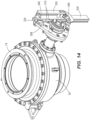
- the emergency release system 50 includes a first valve 54, a second valve 58 that is aligned with the first valve 54 along axis A and that is selectively secured to the first valve 58 by an emergency release coupler 62, and an actuator assembly 64 that has an actuator mechanism 66 (e.g., a scotch-yoke mechanism) and a double-stroke hydraulic cylinder 70 (e.g., a piston-cylinder assembly).
- an actuator mechanism 66 e.g., a scotch-yoke mechanism
- a double-stroke hydraulic cylinder 70 e.g., a piston-cylinder assembly
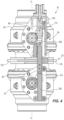
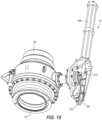
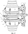
- the first and the second valves 54, 58 can be block valves (e.g., ball valves) or other types of valves that are suitable for closing off flow of fluid. As will be understood, each valve 54, 58 is manipulatable between an open position permitting fluid flow through the emergency release system 50 and a closed position that inhibits fluid flow. With reference to Figs. 2-4 , 14 , 15 , and 17 , the first valve 54 has a flange 74 (best seen in Fig. 14 ) that is sized and shaped to abut a flange 78 (best seen in Fig. 15 ) on the second valve 58. The first valve 54 also has a first valve actuator 82 (best seen in Figs.
- the second valve 58 also has a second valve actuator 86 (best seen in Figs. 2-4 ) that is manipulatable to vary the second valve 58 between open and closed positions (e.g., pivotable 90 degrees).
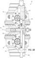
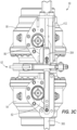
- Each of the first and the second valve actuators 82, 86 is movable between a first position in which the respective first and valves 54, 58 are open (see Figs. 2 , 3A , 4 , 6-7 , and 22 ), and a second position in which the respective first and the second valves 54, 58 are closed (see Figs. 3B , 9-10 , 12-13 , 22 ).
- the coupler 62 includes a first clamp member 120 and a second clamp member 124 that are coupled together and define a breakaway coupler mechanism.
- the first clamp member 120 has a first end 136 and a second end 140 opposite the first end 136, and an arcuately shape portion 142 that is disposed between the first and second ends 136, 140 and that has an arcuate channel 144.
- the second clamp member 124 has a first end 150 and a second end 154 opposite the first end 150, and an arcuately shape portion 158 that is disposed between the first and second ends 150, 154 and that has an arcuate channel 162.
- the channels 144, 162 are complementary to and engage the abutting flanges 74, 78 of the first and second valves 54, 58 to secure the valves 54, 58 together when the emergency release system 50 is assembled.
- first ends 136, 150 of the first and second clamp members 120, 124 are pivotally coupled to a coupler bracket 168 that attaches to the first valve 54.
- a first support 172 couples the first clamp member 120 to the coupler bracket 168 (e.g., via a threaded shaft or another attachment device), and a second support 176 couples the second clamp member 124 to the coupler bracket 168 (e.g., via a threaded shaft or another attachment device) opposite the first support 172.
- the first support 172 includes a hinged connection 180 (e.g., a pinned connection) so that the first clamp member 120 can pivot or otherwise move relative to the second clamp member 124 and the coupler bracket 168.
- the second support 176 includes a hinged connection 182 (e.g., a pinned connection) so that the second clamp member 124 can pivot or otherwise move relative to the first clamp member 120 and the coupler bracket 168.
- Fasteners 184, 186 help secure the supports 172, 176 to the coupler bracket.
- the second end 154 of the second clamp member 124 includes gate brackets 185 that are attached to opposite sides of the clamp member 124 and that cooperate to define a channel 186.
- Each gate bracket 185 also defines an arcuate pocket 187.
- the second ends 140, 154 of the first and second clamp members 120, 124 are selectively coupled to each other by a gate 188.
- the gate 188 has a first end 192 that is pivotally coupled to the second end 140 of the first clamp member 120, and a second end 196 that is removably coupled to the second end 154 of the second clamp member 124 via the gate brackets 185. As shown in Fig.
- the gate 188 includes lock elements 208 that are coupled to and movable relative to the second end 196 (e.g., rotatable or pivotable movement).
- the lock elements 208 engage the pockets 187 when the gate 188 is closed to secure the coupler 62 to the valves 54, 58. More specifically, the illustrated lock elements 208 pivot to clear the edges of the gate brackets 185, and then pivot back to engage the pockets 187.
- the complementary shapes and arrangement between the pockets 187 and the lock elements 208 define an over-center mechanism that holds the gate 188 in place and inhibits back-driving or release of the gate 188 from the gate brackets 187 absent a force applied to the gate 188.
- the gate 188 snaps down into the locked position (best seen in Fig. 18 ) after the lock elements 208 engage the pockets 187 (one of the equilibrium states of the over-center mechanism; the other equilibrium state being the unlocked position shown in Fig. 19 ) to hold the gate 188 in place and secure the clamp members 120, 124 to each other at the second ends 140, 154.
- the actuator mechanism 66 includes a dual rod 298 that has a first rod member 300 selectively coupled to a second rod member 304 by a rotatable latch 308.
- the first rod member 300 includes a first pin or projection 312 that engages and rotates the first valve actuator 82 about an axis of rotation between the first and the second positions.
- the second rod member 304 includes a second pin or projection 314 that engages and rotates the second valve actuator 86 about an axis of rotation between the first and the second positions.
- the axes of rotation are perpendicular to the page with respect to Fig. 4 .
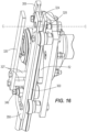
- the first rod member 300 is defined by plates 316 that are spaced apart to define a gap 324 ( Fig. 14 ) and that move together when the dual rod 298 is actuated. As shown in Figs. 3A , 6 , 7 , 10 , 12 , 14 , 16 , a safety plate 326 is attached to the first rod member 300 via spacers 327, and a stop 348 is coupled to an end of the first rod member 300 and is engageable with a bracket 358 (e.g., coupled to the first valve 54) to stop further movement of the actuator mechanism 66 in the downward direction (as viewed in the Figures).
- a bracket 358 e.g., coupled to the first valve 54
- the second rod member 304 has a latch receiver 332 ( Fig. 15 ) that is engageable by the latch 308.
- the latch 308 has a first end 328 that is disposed in the gap 324 and that is pivotably secured to the first rod member 300 as described in detail below.
- the latch 308 has a second end 330 that defines a latch feature 332 (e.g., a projection that has is wider or thicker than a central portion 334 of the latch 308) that selectively couples with the latch receiver 332.
- the latch feature 332 engages the latch receiver 324 to secure the rod members 300, 304 together.
- the latch 308 is movable (pivotable or rotatable) from a latched position (in which the first and second rod members 300, 304 are attached to each other) to an unlatched position (in which the first and second rod members 300, 304 are detached from each other) by a latch actuator 338.
- the latch 308 is pivotally coupled to the first rod member 300 by a latch actuator 338.
- the latch actuator 338 has an eccentric pin 340 including a post 342 with an axis B onto which the latch 308 is mounted for movement with the latch actuator 338 and an eccentric portion 344 coupled to the post 342.
- the eccentric pin 340 is rotatable about an axis C, which is offset from the axis B ( Figs. 16 and 32), when the eccentric portion 344 engages a projection 346 on the first valve 58, as will be discussed in greater detail below.
- the second rod member 304 also includes a gate actuator 352.
- the gate actuator 352 is wedge-shaped, although other shapes are possible. In general, the gate actuator 352 is shaped or positioned to engage the gate 188 and move the gate 188 to the unlocked position.
- the actuator mechanism 66 includes a connected state and a disconnected state.
- the first and the second rod members 300, 304 are coupled to one another via the latch 308, which is aligned with both the first and the second rod members 300, 304 along an axis D.
- the latch 308 is disengaged from the latch feature 332 and the first and the second rod members 300, 304 are separated from one another. As shown, the latch 308 is rotated out of alignment relative to the axis D (e.g., perpendicular to the axis D).
- the cylinder 70 is configured to move the actuator mechanism 66 from the connected state to the disconnected state.
- the cylinder 70 is coupled to the second valve 58 by a bracket 272.
- the cylinder 70 includes a housing 400 with a first end 404 that is coupled to the bracket 272, and a second end 408 that extends from the bracket 272.
- the housing 400 also has a first piston 412, a second piston 416, a first port 420, a second port 424, and a third port 428.
- the first piston 412 extends from the first end 404 of the housing 400 and is received by and secured to the second rod member 304.
- the first and second pistons 412, 416 are movable relative to the housing 400 and each other. That is, the pistons 412, 416 of the cylinder 70 are movable among first, second, and third positions to selectively move the dual rod 298.
- the first position shown in Figs. 5 and 22
- the first piston 412 extends beyond the housing 400 by a first distance 436
- the second piston 416 is retained entirely within the housing (i.e., a distance between the second end 408 of the housing 400 and the second piston 416 is negligible).
- the second position shown in Figs.
- the first piston 412 extends beyond the housing 400 to a second distance 440, and the second piston 416 is spaced apart from the second end 408 of the housing 400.
- the first piston 412 extends beyond the housing 400 to a third distance 448, and the second piston 416 remains spaced apart from the second end 408 of housing 400.
- the emergency release system 50 is configured to respond to a first shutdown condition (ESD1), a first shutdown condition override, and a second shutdown condition (ESD2).
- ESD1 a first shutdown condition
- ESD2 a second shutdown condition
- the first shutdown condition occurs if the position monitoring system 30 determines that the vessel has drifted away from the riser 14 by a first distance from the riser 14.
- the first shutdown condition override occurs if the position monitoring system 30 determines that the vessel's drift has ceased, or the vessel has drifted back toward the riser 14 (i.e. drifted back to a distance between the initial distance and the first distance).
- the second shutdown condition occurs if the position monitoring system 30 determines that the vessel has drifted from the riser and reached a second distance from the riser 14 that is farther than the first distance and up to the predetermined distance that the loading arm 10 can extend. Additionally or alternatively, a user may actuate another mechanism (not shown) to achieve the first shutdown condition, the first shutdown condition override, or the second shutdown condition.
- the emergency release system 50 When the loading arm 10 is fluidly connected to the vessel and the vessel is at or near the initial distance from the riser 14 the emergency release system 50 is in a first state ( Figs. 2-7 and 22A ).
- the first and the second valves 54, 58 are open thereby allowing product to be transferred to or from the vessel.
- the first and the second clamp members 120, 124 of the coupler 62 engage the abutting flanges 74, 78 of the first and second valves 54, 58, and the gate 188 is secured between the second ends 140, 154 of the first and the second clamp members 120, 124.
- the emergency release system 50 moves from the first state ( Figs. 2-7 , 22A ) to a second state ( Figs. 8-10 , 22B ).
- the cylinder 70 applies a first stroke such that fluid (i.e., hydraulic fluid, pneumatic fluid, or the like) introduced through the first port 420 moves the first and second pistons 412, 416 from the first position ( Figs. 5 and 22A ) to the second position ( Figs. 8 and 22B ).
- fluid i.e., hydraulic fluid, pneumatic fluid, or the like
- the actuator mechanism In the second state, the actuator mechanism remains in the connected state, and therefore the latch 308 of the actuator mechanism 66 remains parallel to the axis D such that the first and second rod members 300, 304 remain coupled to one another. Additionally, in the second state, at least a portion of the safety plate 326 remains adjacent the gate 188 of the coupler 62, the gate 188 remains secured between the first and the second clamp members 120, 124, and the lock elements 208 remain positioned within the pockets 187 of the second clamp member 124.
- the emergency release system 50 moves from the second state ( Figs. 8-10 , 22B ) back to the first state ( Figs. 2-7 , 22C ).
- the cylinder 70 is actuated such that fluid (i.e., hydraulic fluid, pneumatic fluid, or the like) introduced through the third port 428 moves the first and second pistons 412, 416 from the second position ( Figs. 8 and 22B ) back to the first position ( Figs. 5 , and 22C ).
- fluid i.e., hydraulic fluid, pneumatic fluid, or the like
- Such movement of the first and second pistons 412, 416 causes the second rod member 304 of the actuator mechanism 66 to translate in a second direction 504 along the axis D ( Fig. 3 ).
- the movement of the actuator mechanism 66 causes the pins 312, 314 of each of the first and second rod members 300, 304 to engage the respective first and second valve actuators 82, 86 thereby forcing the first and second valve actuators 82, 86 to move from their second position to their first position to re-open the respective first and second valves 54, 58.
Landscapes
- Engineering & Computer Science (AREA)
- Mechanical Engineering (AREA)
- General Engineering & Computer Science (AREA)
- Fluid-Pressure Circuits (AREA)
- Quick-Acting Or Multi-Walled Pipe Joints (AREA)
- Loading And Unloading Of Fuel Tanks Or Ships (AREA)
Claims (12)
- Ein Notentriegelungssystem (50) für ein Fluidtransfersystem, das ein erstes Ventil (54) und ein zweites Ventil (56), das selektiv mit dem ersten Ventil fluidgekoppelt ist, aufweist, wobei das Notentriegelungssystem (50) Folgendes beinhaltet:einen Losbrechkopplermechanismus, der in das erste Ventil (54) und das zweite Ventil (56) eingreifen kann, um das erste Ventil (54) und das zweite Ventil (56) entriegelbar aneinander zu koppeln, wobei der Losbrechkopplermechanismus Folgendes umfasst:ein erstes Klemmelement (120), das in das erste und das zweite Ventil (54, 56) eingreift, wobei das erste Klemmelement (120) ein erstes Ende (136) und ein zweites Ende (140) aufweist; undein zweites Klemmelement (124), das in das erste und das zweite Ventil (54, 56) eingreift, wobei das zweite Klemmelement (124) ein erstes Ende (150), das mit dem ersten Ende (136) des ersten Klemmelements (120) gekoppelt ist, und ein zweites Ende (154) aufweist, undeine Blende (188), die entriegelbar mit dem zweiten Ende (140) des ersten Klemmelements (120) und dem zweiten Ende (154) des zweiten Klemmelements (124) gekoppelt ist und die den Losbrechkopplermechanismus auf dem ersten Ventil (54) und dem zweiten Ventil (56) hält, wenn die Blende (188) in einer verriegelten Position positioniert ist, in der die Blende (188) mit dem zweiten Ende (140) des ersten Klemmelements (120) und dem zweiten Ende (154) des zweiten Klemmelements (124) gekoppelt ist;einen Aktuatormechanismus (66), der in das erste Ventil (54) und das zweite Ventil (54) eingreifen kann, wobei der Aktuatormechanismus (66) einen Blendenaktuator (352) und ein Sicherungsblech (326) umfasst, wobei der Blendenaktuator (352) konfiguriert ist, um in die Blende (188) des Losbrechkopplermechanismus einzugreifen, während sich der Aktuatormechanismus (66) von einem verbundenen Zustand in einen nichtverbundenen Zustand bewegt und das Sicherungsblech (326) neben der Blende (188) positioniert ist, wenn sich der Aktuatormechanismus (66) in dem verbundenen Zustand befindet, um einen unbeabsichtigten Antrieb der Blende (188) aus der verriegelten Position zu verhindern; undeine Kolben-Zylinder-Anordnung, die konfiguriert ist, um in den Aktuatormechanismus (66) einzugreifen, um das erste und das zweite Ventil (54, 56) selektiv und gleichzeitig zu schließen und den Losbrechkopplermechanismus aus dem ersten Ventil (54) und dem zweiten Ventil (56) zu lösen.
- Notentriegelungssystem (50) gemäß Anspruch 1, wobei der Aktuatormechanismus (66) einen ersten Stift (312) und einen zweiten Stift (314) aufweist, wobei der erste Stift (312) in einen ersten Ventilaktuator (82) des ersten Ventils (54) eingreift, um den ersten Ventilaktuator (82) um eine Drehachse zwischen einer ersten Position und einer zweiten Position zu drehen und der zweite Stift (314) in einen zweiten Ventilaktuator (86) des zweiten Ventils (54) eingreift, um den zweiten Ventilaktuator (86) um eine Drehachse zwischen einer ersten Position und einer zweiten Position zu drehen.
- Notentriegelungssystem (50) gemäß Anspruch 1, wobei die Blende (188) ein erstes Ende (192) aufweist, das in das zweite Ende (140) des ersten Klemmelements (120) eingehängt ist, und ein zweites Ende (196) entfernbar an das zweite Ende (154) des zweiten Klemmelements (124) gekoppelt ist.
- Notentriegelungssystem (50) gemäß Anspruch 1, wobei die Kolben-Zylinder-Anordnung Folgendes beinhaltet:einen Zylinder (70), der ein Gehäuse (400) mit einem ersten Ende (404) aufweist, das mit einem des ersten Ventils und des zweiten Ventils (54, 56) gekooppelt ist, und ein zweites Ende (408), das sich von dem ersten Ende (404) erstreckt; undeinen Kolben (412), der teilweise innerhalb des Gehäuses (400) positioniert ist, wobei sich der Kolben von dem Gehäuse (400) erstreckt und an dem Aktuatormechanismus (66) gesichert ist.
- Notentriegelungssystem (50) gemäß Anspruch 4, wobei der Kolben (70) zwischen einer ersten Position, einer zweiten Position und einer dritten Position bewegt werden kann.
- Notentriegelungssystem (50) gemäß Anspruch 5, wobei, wenn sich der Kolben (70) in eine erste Richtung bewegt, sich der Kolben (70) von der ersten Position in die zweite Position bewegt, wodurch verursacht wird, dass der Aktuatormechanismus (66) in einen ersten Ventilaktuator (82) des ersten Ventils (54), und einen zweiten Ventilaktuator (86) des zweiten Ventils (56) eingreift, wodurch der erste Ventilaktuator (82) und der zweite Ventilaktuator (86) zwischen den ersten Positionen und den zweiten Positionen bewegt werden,wobei optional kontinuierliche Bewegung des Kolbens (70) in die erste Richtung den Kolben (70) von der zweiten Position in die dritte Position bewegt, wodurch verursacht wird, dass der Losbrechkopplermechanismus das erste Ventil (54) aus dem zweiten Ventil (56) löst oderwobei optional, wenn sich der Kolben (70) in eine zweite Richtung bewegt, sich der Kolben (70) von der zweiten Position in die erste Position bewegt, wodurch verursacht wird, dass der Aktuatormechanismus (66) in den ersten Ventilaktuator (82) des ersten Ventils (54) und den zweiten Ventilaktuator (86) des zweiten Ventils (56) eingreift, wodurch der erste Ventilaktuator (82) und der zweite Ventilaktuator (86) zwischen den zweiten Positionen und den ersten Positionen bewegt werden.
- Notentriegelungssystem (50) gemäß Anspruch 5, wobei der Kolben (70) ein erster Kolben (70) ist und die Kolben-Zylinder-Anordnung ferner Folgendes beinhaltet:
einen zweiten Kolben (416), der eingerichtet ist, um dem ersten Kolben (70) beim Bewegen in mindestens eine von der ersten Position, der zweiten Position oder der dritten Position zu helfen. - Notentriegelungssystem (50) gemäß Anspruch 1, wobei der Aktuatormechanismus (66) eine doppelte Stange (298) mit einem ersten Stangenelement (300) und einem zweiten Stangenelement (304), das entriegelbar an dem ersten Stangenelement (300) befestigt ist, beinhaltet, wobei das erste Stangenelement (300) in das erste Ventil (54) eingreifen kann und das zweite Stangenelement (304) in das zweite Ventil (56) eingreifen kann.
- Notentriegelungssystem (50) gemäß Anspruch 8, wobei die Kolben-Zylinder-Anordnung einen Kolben (412) umfasst, der mit dem zweiten Stangenelement (304) gekoppelt ist, um den Aktuatormechanismus (66) von einem verbundenen Zustand, in dem das erste und zweite Stangenelement (300, 304) gekoppelt sind, in einen gelösten Zustand, in dem das erste und das zweite Stangenelement (300, 304) voneinander getrennt sind, zu bewegen.
- Notentriegelungssystem (50) gemäß Anspruch 8, wobei eine Zunge (308) zwischen dem ersten Stangenelement (300) und dem zweiten Stangenelement (304) angeordnet ist und diese selektiv koppelt,wobei optional die Zunge (308) ein erstes Ende (328), das an dem ersten Stangenelement (300) gesichert ist, und ein zweites Ende (330) umfasst, das selektiv an dem zweiten Stangenelement (304) befestigt ist, wobei das zweite Ende (330) ein Zungenmerkmal (332) umfasst, oderwobei optional die Zunge (308) durch einen Zungenaktuator (338), der einen exzentrischen Stift (340) mit einem exzentrischen Pfosten (342) und einem exzentrischen Abschnitt (344), der an den Pfosten (342) gekoppelt ist, aufweist, wobei die Zunge (308) durch den Pfosten (342) an dem ersten Stangenelement (300) montiert ist.
- Ein Verfahren zum Freigeben einer Verbindung zwischen dem ersten und dem zweiten Ventil (54, 56) eines Fluidtransfersystems unter Verwendung eines Notentriegelungssystems (50) gemäß einem der Ansprüche 1-10, wobei das Verfahren Folgendes beinhaltet:Detektieren einer ersten Stilllegungsbedingung;Betätigen des Aktuatormechanismus (66), der mit dem ersten Ventil (54) und dem zweiten Ventil (56) gekoppelt ist, um das erste und das zweite Ventil (54, 56) zu schließen;Detektieren einer zweiten Stilllegungsbedingung; undEntkoppeln eines Kopplers (62) von dem ersten Ventil (54) und dem zweiten Ventil (56) durch das Betätigen des Aktuatormechanismus (352), um zu verursachen, dass der Blendenaktuator (352) des Aktuatormechanismus (66) in die Blende (188) des Losbrechkopplermechanismus eingreift.
- Verfahren gemäß Anspruch 11 unter Verwendung eines Notentriegelungssystems (50) gemäß Anspruch 5, wobei das Betätigen des Aktuatormechanismus (66) Folgendes beinhaltet:Bewegen des Kolbens (70) von einer ersten Position in eine zweite Position, wobei die zweite Position verursacht, dass der Aktuatormechanismus (66) das erste Ventil (54) und das zweite Ventil (56) ohne Entkoppeln des Kopplers (62) schließt,wobei optional das Entkoppeln des Kopplers (62) Folgendes beinhaltet:
Bewegen des Kolbens (70) von der zweiten Position in eine dritte Position, sodass der Koppler (62) nur folgend darauf entkoppelt wird, dass das erste Ventil (54) und das zweite Ventil (56) geschlossen werden.
Applications Claiming Priority (3)
| Application Number | Priority Date | Filing Date | Title |
|---|---|---|---|
| US201862731450P | 2018-09-14 | 2018-09-14 | |
| EP19858913.7A EP3850259B1 (de) | 2018-09-14 | 2019-09-13 | Notentriegelungssystem und entriegelungsverfahren |
| PCT/US2019/051145 WO2020056351A1 (en) | 2018-09-14 | 2019-09-13 | Dual control emergency release system |
Related Parent Applications (1)
| Application Number | Title | Priority Date | Filing Date |
|---|---|---|---|
| EP19858913.7A Division EP3850259B1 (de) | 2018-09-14 | 2019-09-13 | Notentriegelungssystem und entriegelungsverfahren |
Publications (3)
| Publication Number | Publication Date |
|---|---|
| EP4296218A2 EP4296218A2 (de) | 2023-12-27 |
| EP4296218A3 EP4296218A3 (de) | 2024-02-21 |
| EP4296218B1 true EP4296218B1 (de) | 2025-04-23 |
Family
ID=69778553
Family Applications (2)
| Application Number | Title | Priority Date | Filing Date |
|---|---|---|---|
| EP23207827.9A Active EP4296218B1 (de) | 2018-09-14 | 2019-09-13 | Notentriegelungssystem und entriegelungsverfahren |
| EP19858913.7A Active EP3850259B1 (de) | 2018-09-14 | 2019-09-13 | Notentriegelungssystem und entriegelungsverfahren |
Family Applications After (1)
| Application Number | Title | Priority Date | Filing Date |
|---|---|---|---|
| EP19858913.7A Active EP3850259B1 (de) | 2018-09-14 | 2019-09-13 | Notentriegelungssystem und entriegelungsverfahren |
Country Status (5)
| Country | Link |
|---|---|
| US (1) | US11906098B2 (de) |
| EP (2) | EP4296218B1 (de) |
| PH (1) | PH12021550569A1 (de) |
| SG (1) | SG11202102623UA (de) |
| WO (1) | WO2020056351A1 (de) |
Families Citing this family (3)
| Publication number | Priority date | Publication date | Assignee | Title |
|---|---|---|---|---|
| WO2022096044A1 (de) | 2020-11-04 | 2022-05-12 | Koz Loading Solutions | Notlöseeinrichtung für eine fluidleitung |
| CN114183579B (zh) * | 2021-12-02 | 2024-02-13 | 连云港杰瑞自动化有限公司 | 一种lng输送与转驳系统用紧急脱离装置 |
| JP2023132768A (ja) * | 2022-03-11 | 2023-09-22 | Tbグローバルテクノロジーズ株式会社 | 流体荷役装置用の緊急離脱装置 |
Family Cites Families (8)
| Publication number | Priority date | Publication date | Assignee | Title |
|---|---|---|---|---|
| IT1109855B (it) * | 1979-01-08 | 1985-12-23 | Bormioli Giorgio | Dispositivo di collegamento a sgancio rapido per componenti idraulici flangiati |
| EP1922506B1 (de) | 2005-08-09 | 2013-06-26 | FMC Technologies S.A. | Nottrennsystem |
| JP5216350B2 (ja) * | 2008-02-05 | 2013-06-19 | ニイガタ・ローディング・システムズ株式会社 | 流体荷役装置における緊急切り離し装置 |
| JP5965153B2 (ja) * | 2012-02-07 | 2016-08-03 | 東京貿易エンジニアリング株式会社 | 流体荷役装置における緊急離脱装置 |
| GB2514996B (en) * | 2013-04-10 | 2016-02-10 | Alpha Process Control | Breakaway coupling |
| KR101649796B1 (ko) * | 2014-09-26 | 2016-08-30 | 제일기술산업(주) | 유체하역시스템의 긴급분리장치 |
| GB2536696B (en) * | 2015-03-26 | 2018-04-11 | Klaw Products Ltd | Assembly for transferring matter between first and second objects separated by a distance |
| JP6348924B2 (ja) * | 2016-04-20 | 2018-06-27 | 東京貿易エンジニアリング株式会社 | 流体荷役装置における緊急離脱装置 |
-
2019
- 2019-09-13 SG SG11202102623UA patent/SG11202102623UA/en unknown
- 2019-09-13 WO PCT/US2019/051145 patent/WO2020056351A1/en not_active Ceased
- 2019-09-13 EP EP23207827.9A patent/EP4296218B1/de active Active
- 2019-09-13 EP EP19858913.7A patent/EP3850259B1/de active Active
-
2021
- 2021-03-12 US US17/199,783 patent/US11906098B2/en active Active
- 2021-03-15 PH PH12021550569A patent/PH12021550569A1/en unknown
Also Published As
| Publication number | Publication date |
|---|---|
| US20210199228A1 (en) | 2021-07-01 |
| EP4296218A2 (de) | 2023-12-27 |
| EP4296218A3 (de) | 2024-02-21 |
| EP3850259A4 (de) | 2022-06-22 |
| EP3850259B1 (de) | 2023-12-06 |
| SG11202102623UA (en) | 2021-04-29 |
| US11906098B2 (en) | 2024-02-20 |
| PH12021550569A1 (en) | 2021-12-06 |
| WO2020056351A1 (en) | 2020-03-19 |
| EP3850259A1 (de) | 2021-07-21 |
Similar Documents
| Publication | Publication Date | Title |
|---|---|---|
| US11906098B2 (en) | Dual control emergency release system | |
| FI111527B (fi) | Lukitusmekanismi lastauspoijun kiinnittämiseksi alukseen | |
| KR101787158B1 (ko) | 분리 가능한 클램핑 모듈을 구비한 연결장치 | |
| EP2215393B1 (de) | Steckverbinder mit integriertem schnellverschluss und -abzug sowie notfallfreigabesystem | |
| US4622997A (en) | Emergency release couplers | |
| US9534716B2 (en) | Structural connector diverting loads away from the cool connector | |
| US8360103B2 (en) | Split valve | |
| US4354522A (en) | Flexible connecting system for pipes with automatic safety release in case of tensile stress | |
| JPH09508457A (ja) | ゼロスピル二重ボールバルブで駆動される緊急分離カップリング | |
| JPS642839B2 (de) | ||
| DK2625093T3 (en) | Device for controlling the valves in a connection / separation device | |
| JPH0223600Y2 (de) | ||
| EP3311057B1 (de) | Sicherheitskupplungsvorrichtung mit absperrventilen zum koppeln zweier fluidleitungsteile | |
| EP2383499B1 (de) | Sicherheitsvorrichtung zur Rohrverbindung | |
| EP0175469A1 (de) | Rohrleitungsverbindungssystem | |
| JP6700898B2 (ja) | 流体荷役装置 | |
| TWM577094U (zh) | Double ball valve emergency release device | |
| GB2114531A (en) | Fluid loaders | |
| JPH0144600B2 (de) | ||
| SE537939C2 (sv) | Kopplingsanordning för upprättande av en fluidförbindelse mellan en första och andra behållare samt förfarande vid en sådan anordning |
Legal Events
| Date | Code | Title | Description |
|---|---|---|---|
| PUAI | Public reference made under article 153(3) epc to a published international application that has entered the european phase |
Free format text: ORIGINAL CODE: 0009012 |
|
| STAA | Information on the status of an ep patent application or granted ep patent |
Free format text: STATUS: THE APPLICATION HAS BEEN PUBLISHED |
|
| AC | Divisional application: reference to earlier application |
Ref document number: 3850259 Country of ref document: EP Kind code of ref document: P |
|
| AK | Designated contracting states |
Kind code of ref document: A2 Designated state(s): AL AT BE BG CH CY CZ DE DK EE ES FI FR GB GR HR HU IE IS IT LI LT LU LV MC MK MT NL NO PL PT RO RS SE SI SK SM TR |
|
| REG | Reference to a national code |
Ref legal event code: R079 Free format text: PREVIOUS MAIN CLASS: B67D0007320000 Ipc: F16L0029000000 Ref country code: DE Ref document number: 602019069231 Country of ref document: DE |
|
| PUAL | Search report despatched |
Free format text: ORIGINAL CODE: 0009013 |
|
| AK | Designated contracting states |
Kind code of ref document: A3 Designated state(s): AL AT BE BG CH CY CZ DE DK EE ES FI FR GB GR HR HU IE IS IT LI LT LU LV MC MK MT NL NO PL PT RO RS SE SI SK SM TR |
|
| RIC1 | Information provided on ipc code assigned before grant |
Ipc: B67D 7/32 20100101ALI20240116BHEP Ipc: F16L 55/10 20060101ALI20240116BHEP Ipc: F16L 37/08 20060101ALI20240116BHEP Ipc: B67D 9/02 20100101ALI20240116BHEP Ipc: B67D 9/00 20100101ALI20240116BHEP Ipc: B63B 27/34 20060101ALI20240116BHEP Ipc: B63B 27/30 20060101ALI20240116BHEP Ipc: B63B 27/25 20060101ALI20240116BHEP Ipc: F16L 29/00 20060101AFI20240116BHEP |
|
| STAA | Information on the status of an ep patent application or granted ep patent |
Free format text: STATUS: REQUEST FOR EXAMINATION WAS MADE |
|
| 17P | Request for examination filed |
Effective date: 20240531 |
|
| RBV | Designated contracting states (corrected) |
Designated state(s): AL AT BE BG CH CY CZ DE DK EE ES FI FR GB GR HR HU IE IS IT LI LT LU LV MC MK MT NL NO PL PT RO RS SE SI SK SM TR |
|
| GRAP | Despatch of communication of intention to grant a patent |
Free format text: ORIGINAL CODE: EPIDOSNIGR1 |
|
| STAA | Information on the status of an ep patent application or granted ep patent |
Free format text: STATUS: GRANT OF PATENT IS INTENDED |
|
| RIC1 | Information provided on ipc code assigned before grant |
Ipc: B67D 7/32 20100101ALI20241115BHEP Ipc: F16L 55/10 20060101ALI20241115BHEP Ipc: F16L 37/08 20060101ALI20241115BHEP Ipc: B67D 9/02 20100101ALI20241115BHEP Ipc: B67D 9/00 20100101ALI20241115BHEP Ipc: B63B 27/34 20060101ALI20241115BHEP Ipc: B63B 27/30 20060101ALI20241115BHEP Ipc: B63B 27/25 20060101ALI20241115BHEP Ipc: F16L 29/00 20060101AFI20241115BHEP |
|
| INTG | Intention to grant announced |
Effective date: 20241129 |
|
| GRAS | Grant fee paid |
Free format text: ORIGINAL CODE: EPIDOSNIGR3 |
|
| GRAA | (expected) grant |
Free format text: ORIGINAL CODE: 0009210 |
|
| STAA | Information on the status of an ep patent application or granted ep patent |
Free format text: STATUS: THE PATENT HAS BEEN GRANTED |
|
| AC | Divisional application: reference to earlier application |
Ref document number: 3850259 Country of ref document: EP Kind code of ref document: P |
|
| AK | Designated contracting states |
Kind code of ref document: B1 Designated state(s): AL AT BE BG CH CY CZ DE DK EE ES FI FR GB GR HR HU IE IS IT LI LT LU LV MC MK MT NL NO PL PT RO RS SE SI SK SM TR |
|
| REG | Reference to a national code |
Ref country code: GB Ref legal event code: FG4D |
|
| REG | Reference to a national code |
Ref country code: CH Ref legal event code: EP |
|
| REG | Reference to a national code |
Ref country code: DE Ref legal event code: R096 Ref document number: 602019069231 Country of ref document: DE |
|
| REG | Reference to a national code |
Ref country code: IE Ref legal event code: FG4D |
|
| REG | Reference to a national code |
Ref country code: NL Ref legal event code: MP Effective date: 20250423 |
|
| PG25 | Lapsed in a contracting state [announced via postgrant information from national office to epo] |
Ref country code: NL Free format text: LAPSE BECAUSE OF FAILURE TO SUBMIT A TRANSLATION OF THE DESCRIPTION OR TO PAY THE FEE WITHIN THE PRESCRIBED TIME-LIMIT Effective date: 20250423 |
|
| REG | Reference to a national code |
Ref country code: AT Ref legal event code: MK05 Ref document number: 1788034 Country of ref document: AT Kind code of ref document: T Effective date: 20250423 |
|
| PG25 | Lapsed in a contracting state [announced via postgrant information from national office to epo] |
Ref country code: FI Free format text: LAPSE BECAUSE OF FAILURE TO SUBMIT A TRANSLATION OF THE DESCRIPTION OR TO PAY THE FEE WITHIN THE PRESCRIBED TIME-LIMIT Effective date: 20250423 Ref country code: PT Free format text: LAPSE BECAUSE OF FAILURE TO SUBMIT A TRANSLATION OF THE DESCRIPTION OR TO PAY THE FEE WITHIN THE PRESCRIBED TIME-LIMIT Effective date: 20250825 Ref country code: ES Free format text: LAPSE BECAUSE OF FAILURE TO SUBMIT A TRANSLATION OF THE DESCRIPTION OR TO PAY THE FEE WITHIN THE PRESCRIBED TIME-LIMIT Effective date: 20250423 |
|
| REG | Reference to a national code |
Ref country code: LT Ref legal event code: MG9D |
|
| PG25 | Lapsed in a contracting state [announced via postgrant information from national office to epo] |
Ref country code: NO Free format text: LAPSE BECAUSE OF FAILURE TO SUBMIT A TRANSLATION OF THE DESCRIPTION OR TO PAY THE FEE WITHIN THE PRESCRIBED TIME-LIMIT Effective date: 20250723 Ref country code: GR Free format text: LAPSE BECAUSE OF FAILURE TO SUBMIT A TRANSLATION OF THE DESCRIPTION OR TO PAY THE FEE WITHIN THE PRESCRIBED TIME-LIMIT Effective date: 20250724 |
|
| PG25 | Lapsed in a contracting state [announced via postgrant information from national office to epo] |
Ref country code: PL Free format text: LAPSE BECAUSE OF FAILURE TO SUBMIT A TRANSLATION OF THE DESCRIPTION OR TO PAY THE FEE WITHIN THE PRESCRIBED TIME-LIMIT Effective date: 20250423 |
|
| PGFP | Annual fee paid to national office [announced via postgrant information from national office to epo] |
Ref country code: IT Payment date: 20250923 Year of fee payment: 7 |
|
| PG25 | Lapsed in a contracting state [announced via postgrant information from national office to epo] |
Ref country code: BG Free format text: LAPSE BECAUSE OF FAILURE TO SUBMIT A TRANSLATION OF THE DESCRIPTION OR TO PAY THE FEE WITHIN THE PRESCRIBED TIME-LIMIT Effective date: 20250423 |
|
| PGFP | Annual fee paid to national office [announced via postgrant information from national office to epo] |
Ref country code: GB Payment date: 20250929 Year of fee payment: 7 |
|
| PG25 | Lapsed in a contracting state [announced via postgrant information from national office to epo] |
Ref country code: HR Free format text: LAPSE BECAUSE OF FAILURE TO SUBMIT A TRANSLATION OF THE DESCRIPTION OR TO PAY THE FEE WITHIN THE PRESCRIBED TIME-LIMIT Effective date: 20250423 |
|
| PG25 | Lapsed in a contracting state [announced via postgrant information from national office to epo] |
Ref country code: AT Free format text: LAPSE BECAUSE OF FAILURE TO SUBMIT A TRANSLATION OF THE DESCRIPTION OR TO PAY THE FEE WITHIN THE PRESCRIBED TIME-LIMIT Effective date: 20250423 |
|
| PGFP | Annual fee paid to national office [announced via postgrant information from national office to epo] |
Ref country code: FR Payment date: 20250929 Year of fee payment: 7 |
|
| PG25 | Lapsed in a contracting state [announced via postgrant information from national office to epo] |
Ref country code: RS Free format text: LAPSE BECAUSE OF FAILURE TO SUBMIT A TRANSLATION OF THE DESCRIPTION OR TO PAY THE FEE WITHIN THE PRESCRIBED TIME-LIMIT Effective date: 20250723 |
|
| PG25 | Lapsed in a contracting state [announced via postgrant information from national office to epo] |
Ref country code: IS Free format text: LAPSE BECAUSE OF FAILURE TO SUBMIT A TRANSLATION OF THE DESCRIPTION OR TO PAY THE FEE WITHIN THE PRESCRIBED TIME-LIMIT Effective date: 20250823 |
|
| PG25 | Lapsed in a contracting state [announced via postgrant information from national office to epo] |
Ref country code: LV Free format text: LAPSE BECAUSE OF FAILURE TO SUBMIT A TRANSLATION OF THE DESCRIPTION OR TO PAY THE FEE WITHIN THE PRESCRIBED TIME-LIMIT Effective date: 20250423 |
|
| PGFP | Annual fee paid to national office [announced via postgrant information from national office to epo] |
Ref country code: DE Payment date: 20250929 Year of fee payment: 7 |
|
| PG25 | Lapsed in a contracting state [announced via postgrant information from national office to epo] |
Ref country code: SM Free format text: LAPSE BECAUSE OF FAILURE TO SUBMIT A TRANSLATION OF THE DESCRIPTION OR TO PAY THE FEE WITHIN THE PRESCRIBED TIME-LIMIT Effective date: 20250423 Ref country code: DK Free format text: LAPSE BECAUSE OF FAILURE TO SUBMIT A TRANSLATION OF THE DESCRIPTION OR TO PAY THE FEE WITHIN THE PRESCRIBED TIME-LIMIT Effective date: 20250423 |
|
| PG25 | Lapsed in a contracting state [announced via postgrant information from national office to epo] |
Ref country code: CZ Free format text: LAPSE BECAUSE OF FAILURE TO SUBMIT A TRANSLATION OF THE DESCRIPTION OR TO PAY THE FEE WITHIN THE PRESCRIBED TIME-LIMIT Effective date: 20250423 |
|
| PG25 | Lapsed in a contracting state [announced via postgrant information from national office to epo] |
Ref country code: EE Free format text: LAPSE BECAUSE OF FAILURE TO SUBMIT A TRANSLATION OF THE DESCRIPTION OR TO PAY THE FEE WITHIN THE PRESCRIBED TIME-LIMIT Effective date: 20250423 |
|
| REG | Reference to a national code |
Ref country code: DE Ref legal event code: R097 Ref document number: 602019069231 Country of ref document: DE |
|
| PG25 | Lapsed in a contracting state [announced via postgrant information from national office to epo] |
Ref country code: SK Free format text: LAPSE BECAUSE OF FAILURE TO SUBMIT A TRANSLATION OF THE DESCRIPTION OR TO PAY THE FEE WITHIN THE PRESCRIBED TIME-LIMIT Effective date: 20250423 |
|
| PLBE | No opposition filed within time limit |
Free format text: ORIGINAL CODE: 0009261 |
|
| STAA | Information on the status of an ep patent application or granted ep patent |
Free format text: STATUS: NO OPPOSITION FILED WITHIN TIME LIMIT |
|
| REG | Reference to a national code |
Ref country code: CH Ref legal event code: L10 Free format text: ST27 STATUS EVENT CODE: U-0-0-L10-L00 (AS PROVIDED BY THE NATIONAL OFFICE) Effective date: 20260304 |
|
| PG25 | Lapsed in a contracting state [announced via postgrant information from national office to epo] |
Ref country code: RO Free format text: LAPSE BECAUSE OF FAILURE TO SUBMIT A TRANSLATION OF THE DESCRIPTION OR TO PAY THE FEE WITHIN THE PRESCRIBED TIME-LIMIT Effective date: 20250423 |
|
| 26N | No opposition filed |
Effective date: 20260126 |