EP4296164A1 - A rail mounting arrangement for a vehicle, such as an aircraft, and a vehicle equipped with said arrangement - Google Patents
A rail mounting arrangement for a vehicle, such as an aircraft, and a vehicle equipped with said arrangement Download PDFInfo
- Publication number
- EP4296164A1 EP4296164A1 EP22179897.8A EP22179897A EP4296164A1 EP 4296164 A1 EP4296164 A1 EP 4296164A1 EP 22179897 A EP22179897 A EP 22179897A EP 4296164 A1 EP4296164 A1 EP 4296164A1
- Authority
- EP
- European Patent Office
- Prior art keywords
- mounting
- securing
- arrangement
- rail
- mounting member
- Prior art date
- Legal status (The legal status is an assumption and is not a legal conclusion. Google has not performed a legal analysis and makes no representation as to the accuracy of the status listed.)
- Granted
Links
Images





Classifications
-
- B—PERFORMING OPERATIONS; TRANSPORTING
- B64—AIRCRAFT; AVIATION; COSMONAUTICS
- B64D—EQUIPMENT FOR FITTING IN OR TO AIRCRAFT; FLIGHT SUITS; PARACHUTES; ARRANGEMENT OR MOUNTING OF POWER PLANTS OR PROPULSION TRANSMISSIONS IN AIRCRAFT
- B64D11/00—Passenger or crew accommodation; Flight-deck installations not otherwise provided for
- B64D11/06—Arrangements of seats, or adaptations or details specially adapted for aircraft seats
- B64D11/0696—Means for fastening seats to floors, e.g. to floor rails
-
- B—PERFORMING OPERATIONS; TRANSPORTING
- B60—VEHICLES IN GENERAL
- B60N—SEATS SPECIALLY ADAPTED FOR VEHICLES; VEHICLE PASSENGER ACCOMMODATION NOT OTHERWISE PROVIDED FOR
- B60N2/00—Seats specially adapted for vehicles; Arrangement or mounting of seats in vehicles
- B60N2/005—Arrangement or mounting of seats in vehicles, e.g. dismountable auxiliary seats
- B60N2/015—Attaching seats directly to vehicle chassis
- B60N2/01508—Attaching seats directly to vehicle chassis using quick release attachments
- B60N2/01516—Attaching seats directly to vehicle chassis using quick release attachments with locking mechanisms
- B60N2/0155—Attaching seats directly to vehicle chassis using quick release attachments with locking mechanisms with the locking mechanism on the vehicle floor or rail
-
- B—PERFORMING OPERATIONS; TRANSPORTING
- B60—VEHICLES IN GENERAL
- B60N—SEATS SPECIALLY ADAPTED FOR VEHICLES; VEHICLE PASSENGER ACCOMMODATION NOT OTHERWISE PROVIDED FOR
- B60N2/00—Seats specially adapted for vehicles; Arrangement or mounting of seats in vehicles
- B60N2/005—Arrangement or mounting of seats in vehicles, e.g. dismountable auxiliary seats
- B60N2/015—Attaching seats directly to vehicle chassis
- B60N2/01508—Attaching seats directly to vehicle chassis using quick release attachments
- B60N2/01516—Attaching seats directly to vehicle chassis using quick release attachments with locking mechanisms
-
- B—PERFORMING OPERATIONS; TRANSPORTING
- B60—VEHICLES IN GENERAL
- B60N—SEATS SPECIALLY ADAPTED FOR VEHICLES; VEHICLE PASSENGER ACCOMMODATION NOT OTHERWISE PROVIDED FOR
- B60N2/00—Seats specially adapted for vehicles; Arrangement or mounting of seats in vehicles
- B60N2/02—Seats specially adapted for vehicles; Arrangement or mounting of seats in vehicles the seat or part thereof being movable, e.g. adjustable
- B60N2/04—Seats specially adapted for vehicles; Arrangement or mounting of seats in vehicles the seat or part thereof being movable, e.g. adjustable the whole seat being movable
- B60N2/06—Seats specially adapted for vehicles; Arrangement or mounting of seats in vehicles the seat or part thereof being movable, e.g. adjustable the whole seat being movable slidable
- B60N2/08—Seats specially adapted for vehicles; Arrangement or mounting of seats in vehicles the seat or part thereof being movable, e.g. adjustable the whole seat being movable slidable characterised by the locking device
- B60N2/0831—Movement of the latch
- B60N2/0862—Movement of the latch sliding
- B60N2/0875—Movement of the latch sliding in a vertical direction
-
- B—PERFORMING OPERATIONS; TRANSPORTING
- B64—AIRCRAFT; AVIATION; COSMONAUTICS
- B64C—AEROPLANES; HELICOPTERS
- B64C1/00—Fuselages; Constructional features common to fuselages, wings, stabilising surfaces or the like
- B64C1/18—Floors
-
- B—PERFORMING OPERATIONS; TRANSPORTING
- B64—AIRCRAFT; AVIATION; COSMONAUTICS
- B64D—EQUIPMENT FOR FITTING IN OR TO AIRCRAFT; FLIGHT SUITS; PARACHUTES; ARRANGEMENT OR MOUNTING OF POWER PLANTS OR PROPULSION TRANSMISSIONS IN AIRCRAFT
- B64D11/00—Passenger or crew accommodation; Flight-deck installations not otherwise provided for
- B64D11/06—Arrangements of seats, or adaptations or details specially adapted for aircraft seats
-
- F—MECHANICAL ENGINEERING; LIGHTING; HEATING; WEAPONS; BLASTING
- F16—ENGINEERING ELEMENTS AND UNITS; GENERAL MEASURES FOR PRODUCING AND MAINTAINING EFFECTIVE FUNCTIONING OF MACHINES OR INSTALLATIONS; THERMAL INSULATION IN GENERAL
- F16B—DEVICES FOR FASTENING OR SECURING CONSTRUCTIONAL ELEMENTS OR MACHINE PARTS TOGETHER, e.g. NAILS, BOLTS, CIRCLIPS, CLAMPS, CLIPS OR WEDGES; JOINTS OR JOINTING
- F16B1/00—Devices for securing together, or preventing relative movement between, constructional elements or machine parts
- F16B1/02—Means for securing elements of mechanisms after operation
Definitions
- the invention relates to a rail mounting arrangement for a vehicle, preferably an aircraft.
- the invention further relates to a vehicle equipped with said arrangement.
- DE 10 2010 053 892 A1 discloses a seat adjustment device for an aircraft that comprises a seat rail for connection to a floor.
- a worm is provided which can be actuated to adjust the seat connection in relation to the seat rail.
- A1 discloses a guide rail which has a guiding device stretching in a guide direction and a cross-section device with a head section.
- a bar section forms a lateral engagement section stretching in guide direction.
- the head section is formed in sections at a side with recesses for forming multiple laterally aligned latching sections.
- DE 10 2009 028 903 A1 discloses a guide rail, which has a profiled guide unit with a head section.
- the guide unit extends in the guide direction, and has multiple interference sections formed at a distance from each other in the guide direction.
- a fastening unit is provided, which is attached on the module.
- DE 10 2018 122 958 A1 discloses a floor fastening assembly for releasably fastening a leg of a frame to a vehicle floor.
- the assembly comprises a holding pin which can be fixed to the vehicle floor.
- the assembly further comprises a frame fastening element which is set up to be connected to the leg of the frame and which comprises a receiving space for receiving the holding pin.
- a clamping device is set up to be inserted into the receiving space of the frame fastening element in order to connect the frame fastening element to the holding pin in a form-fitting manner.
- seats or rows of seats are frequently attached to seat rails extending in the longitudinal direction of the vehicle.
- Operators of modern commercial aircraft are increasingly looking for more flexible design options for the interior of the passenger cabin. This includes rapid adjustment of the arrangement of seats or seat rows.
- seat spacing between seats arranged one behind the other should be able to be changed as quickly and easily as possible, so that the division of the passenger cabin into a business class zone with more comfortable larger seat spacing and an economy class zone with smaller seat spacing can be changed as quickly, easily and flexibly as possible.
- the invention provides a rail mounting arrangement for a vehicle, preferably for an aircraft, the arrangement comprising:
- the mounting profile portion includes at least one outer lateral side portion that faces outward towards the mounting member.
- the disengagement locking mechanism is partially provided on the at least one outer lateral side portion.
- the mounting member includes at least one inner lateral side portion that faces inward towards the mounting profile portion.
- the disengagement locking mechanism is partially provided on the at least one inner lateral side portion.
- the disengagement locking mechanism includes at least one outer locking groove that is formed on the mounting profile portion and a corresponding number of inner locking grooves that are formed on the mounting member.
- the outer locking groove is arranged on the outer lateral side portion and the inner locking groove is arranged on the inner lateral side portion.
- the mounting profile portion includes a top side portion that faces upward towards the mounting member and extends in a horizontal direction, and the securing mechanism is partially provided on the top side portion.
- the mounting member includes a bottom side portion that faces downward towards the mounting profile portion and extends in a horizontal direction.
- the securing mechanism is partially provided on the bottom side portion.
- the securing mechanism includes a plurality or securing recesses that are formed on the mounting rail and are recessed into the mounting profile portion.
- the securing mechanism includes at least one securing protrusion that protrudes from the mounting member in vertical direction towards the mounting rail and, when the securing mechanism is in a secured state, into the mounting recesses.
- the securing recesses and the securing protrusions are both formed as matching toothed portions that, when the securing mechanism is in a secured state, mesh with each other.
- the securing mechanism comprises a securing member that is insertable between the mounting member and the mounting profile portion and comprises a toothed portion that, when the securing member is inserted and the securing mechanism is in a secured state, meshes with the toothed portion of the mounting profile portion.
- the securing mechanism includes a rotatable securing bolt that is rotatable about an axis that is parallel to the longitudinal direction and includes a toothed portion that, when the securing mechanism is in a secured state, meshes with the toothed portion of the mounting profile portion.
- the plurality of securing recesses is formed as a series of securing holes that are drilled in a vertical direction into the mounting profile portion.
- the at least one securing protrusion is formed as a securing pin that extends in the vertical direction and, when the securing mechanism is in a secured state, is received a securing hole.
- the securing protrusion or the securing pin is movable along the vertical direction between an unsecured state and a secured state via a toolless moving mechanism.
- the mounting rail comprises a support portion made from a fiber reinforced plastic material or a metal material and the mounting profile portion is made from a metal material that is different from the metal material of the support portion.
- the mounting profile portion is attached to the support portion, preferably by rivets that are aligned in a transversal direction of the mounting rail.
- the disengagement locking mechanism is configured such that, when the disengagement locking member is installed, the securing mechanism is forced into the secured state and movement of the mounting member is blocked.
- the invention provides an aircraft or aircraft cabin including a floor portion and an arrangement according to any of the preceding claims, wherein a cabin component is removably attached to the floor portion via the arrangement.
- the mounting member can be placed on the mounting rail and be prevented from coming loose by the disengagement locking mechanism. However, it is still possible to slide the mounting member along the mounting rail to define the end position of the mounting member. Subsequently, the mounting member can be secured to the mounting rail without a tool.
- the disengagement lock and the securing mechanism are cooperative such that by inserting a single lock member, the mounting member is fixed in place on the mounting rail, whereas without the lock member the mounting member can still be slid along the mounting rail.
- an aircraft 10 includes an aircraft cabin 12.
- the aircraft cabin 12 includes a plurality of cabin components 14 that are mounted to a floor portion 16.
- cabin components 14 include, but are not limited to, cabin monuments such as galleys and lavatories, passenger seats, and other floor-mounted components.
- the cabin components 14 are mounted to the floor portion 16 by a rail mounting arrangement 20.
- the rail mounting arrangement 20 comprises a mounting member 22.
- the mounting member 22 may include a mounting strut 24 that is connected to the cabin component 14 (not shown).
- the mounting strut 24 can pivot so as to form an angle between 0 degrees and 90 degrees relative to the horizontal floor portion 16.
- the mounting member 22 preferably supports the mounting strut 24 on at least one flange portion 26.
- the mounting member 22 further comprises a mounting section 28.
- the mounting section 28 preferably has C-shaped cross-section.
- the mounting section 28 includes a pair of lateral legs 30 that extend in a vertical direction.
- the mounting section 28 further comprises a base portion 32 that extends in the horizontal direction. The lateral legs 30 protrude from the base portion 32 downward.
- Each lateral leg 30 preferably includes an inner lateral side portion 34 that is arranged to face towards a mounting channel 36 that is defined by the mounting section 28.
- the inner lateral side portion 34 may include an inner locking groove 38 that is open towards the mounting channel 36.
- the mounting member 22 includes a securing pin 40.
- the securing pin 40 is arranged such that in a retracted position the securing pin 40 is flush or recessed with respect to the mounting channel 36. In other words, the mounting channel 36 is unobstructed when viewed along its longitudinal direction.
- the securing pin 40 can be moved into an extended position, in which the securing pin 40 protrudes from the base portion 32 into the mounting channel 36.
- the mounting member 22 may include a securing lever 42.
- the securing lever 42 is rotatably supported by the mounting member 22.
- the securing lever 42 includes a cam portion that is configured so as to displace the securing pin 40 from the retracted position into the extended position.
- the mounting member 22 may include an elastic member 44 that is arranged so as to press the securing pin 40 against the securing lever 42, specifically the cam portion.
- the rail mounting arrangement 20 further comprises a mounting rail 46 that extends in a longitudinal direction.
- the mounting rail 46 has a support base 48 that extends in a horizontal direction.
- the support base 48 is typically in contact with a lower part of the floor portion 16 of the aircraft cabin 12.
- the mounting rail 46 may further comprise a vertical support 50 that protrudes from the support base 48 upward.
- the mounting rail 46 further includes a mounting profile portion 52.
- the mounting profile portion 52 may comprise a floor board support 54.
- the floor board support 54 supports a plurality of floor boards 56 that form the cabin floor of the aircraft cabin 12.
- the mounting profile portion 52 is configured for mounting the mounting member 22.
- the mounting profile portion 52 is shaped so as to match the mounting section 28.
- the mounting profile portion 52 is preferably configured in a manner which allows the mounting profile portion 52 to be received inside the mounting channel 36.
- the mounting profile portion 52 preferably includes a pair of outer lateral side portions 58.
- Each outer lateral side portion 58 preferably extends in a vertical direction and, when the mounting member 22 is installed, faces the mounting member 22, preferably the respective inner lateral side portions 34.
- the mounting profile portion 52 may further include a top side portion 60.
- the top side portion 60 extends in a horizontal direction and along the longitudinal direction.
- the top side portion 60 is preferably arranged in between the outer lateral side portions 58. Together, the outer lateral side portions 58 and the top side portion 60 may be considered as outward facing surfaces.
- Each outer lateral side portion 58 may include an outer locking groove 62.
- the outer locking groove 62 is arranged such that it faces the inner locking groove 38.
- the inner and outer locking grooves 38, 62 are in cooperation to form a disengagement locking channel 64.
- the disengagement locking channel 64 preferably has a circular or ellipsoidal cross-section.
- the top side portion 60 may include a plurality of securing holes 66, which act as securing recesses 68.
- Each securing recess 68 is recessed from the surface of the top side portion 60 into the mounting profile section 52.
- the securing recesses 68 are shaped such that they can receive the securing pin 40 in a form-fitting manner.
- the rail mounting arrangement 20 may further include a disengagement locking member 70.
- the disengagement locking member 70 preferably includes at least one disengagement locking pin 72.
- the disengagement locking member 70 is configured to be received in the disengagement locking channel 64.
- the disengagement locking pin 72 has the same cross-section as the disengagement locking channel 64.
- the mounting member 22 and the mounting rail 46 are separate from each other.
- the mounting member 22 may be attached to a passenger seat, for example.
- the mounting member 22 is arranged such that the mounting profile portion 52 engages the mounting member 22.
- the mounting profile portion 52 is surrounded on three sides, when viewed in a cross-section, by the mounting section 28.
- the mounting profile portion 52 is received in the mounting channel 36.
- the disengagement locking member 70 is inserted into the disengagement locking channel 64.
- the mounting member 22 may still slide along the longitudinal direction of the mounting rail 46 supported by the mounting profile portion 52.
- the disengagement locking member 70 is inserted into the disengagement locking channels 64, the mounting member 22 is blocked from being removed in the vertical transversal direction of the mounting rail 46.
- the disengagement locking member 70 and the inner and outer locking groove 38, 62 form a disengagement locking mechanism 74. Consequently, in the aforementioned configuration, the disengagement locking mechanism 74 prevents the mounting member 22 from being removed from the mounting profile portion 52 in the vertical direction, while still being moveable along the longitudinal direction of the mounting rail 46.
- the mounting member 22 is slid along the mounting rail 46 until it reaches the desired location.
- a user may operate the securing lever 42 so as to push the securing pin 40 from the retracted position into the extend position.
- the securing pin 40 is received in the securing recess 68 and prevents movement of the mounting member 22 along the longitudinal direction in a form-fitting manner.
- the securing pin 40 is an example of a securing protrusion.
- This securing protrusion and the securing recess 68 form a securing mechanism 76.
- the securing mechanism 76 In the configuration, when the securing pin 40 and the securing recess 68 engage, the securing mechanism 76 is in an engaged state. In the engaged state, the securing mechanism 76 prevents the mounting member 22 from being moved along the mounting rail 46 along the longitudinal direction.
- disengagement locking mechanism 74 and the securing mechanism 76 are separate mechanisms. It is therefore possible for the disengagement locking mechanism 74 to be in a locked state while the securing mechanism 76 in a disengaged state.
- the mounting member 22 includes a fixed securing pin 140.
- the fixed securing pin 140 protrudes from the base portion 32 into the mounting channel 36.
- the mounting member 22 is configured with the fixed securing pin 140 and a second fixed securing pin 142.
- the rail mounting arrangement 20 may include a rail cover 78, which is arranged to cover the unused sections of the mounting profile portion 52.
- the fixed securing pin 140 and as the case may be the second fixed securing pin 142 together with the securing recesses 68 form a securing mechanism 176.
- the mounting member 22 and the mounting rail 46 are separate from each other.
- the mounting member 22 is positioned at the desired location, by inserting the fixed securing pin 140 and if applicable, the second fixed securing pin 142 into the securing recesses 68.
- the securing mechanism 76 is considered to be in an engaged state, since the mounting member 22 cannot be moved along the longitudinal direction of the mounting rail 46 due to the securing pins 140, 142 engaging the mounting profile portion 52 in a form-fitting manner.
- the disengagement locking member 70 is inserted in to the disengagement locking channel 64, whereby the mounting member 22 is prevented from being removed along a vertical direction from the mounting profile portion 52.
- the mounting member 22 is fixed in location and the cabin component 14 that is supported by the mounting member 22 is attached to the floor portion 16.
- the mounting member 22 comprises a toothed portion 240, wherein the protruding teeth form securing protrusions.
- the top side portion 60 also includes a toothed portion 266, wherein the indentations act as securing recesses.
- the installation (and removal) is identical to the second embodiment.
- the mounting member 22 has a flat base portion 332, whereas the mounting profile portion 52, specifically the top side portion 60 includes the toothed portion 266.
- the rail mounting arrangement 20 further includes a securing member 340 that has formed on it a tooth portion 342.
- the mounting member 22 includes an insertion opening 344 that is configured to receive the securing member 340.
- the mounting member 22 may include a spring detent 80 that is arranged to engage the disengagement locking member 70, when it is inserted in the disengagement locking channel 64.
- the mounting member 22 may engage the mounting profile portion 52 in a sliding manner.
- the disengagement locking member 70 is inserted in the disengagement locking channel 64, the mounting member 22 can no longer be removed from the mounting rail 46 along the vertical direction. However, the mounting member 22 may still slide along the longitudinal direction.
- the securing member 342 is inserted into the insertion opening 344. The toothed portion 342 measures with the toothed portion 266 thereby preventing a movement of the mounting member 22 along the longitudinal direction.
- the securing member 340 is part of the securing mechanism 76.
- FIG. 9 a fifth embodiment of the rail mounting arrangement 20 is illustrated wherein the left depicts the securing mechanism 76 in a disengaged state, whereas the right portion of the drawing depicts the securing mechanism 76 in an engaged state.
- the mounting member 22 comprises a securing bolt 440.
- the securing bolt 440 is supported in a rotatable manner and includes a toothed portion 442. Furthermore, the securing bolt 440 includes a flat portion 444.
- the mounting process is similar to the first embodiment. Initially, the mounting member 22 may be attached to the mounting profile portion 52 in a sliding manner by inserting the disengagement locking member 70 into the disengagement locking channel 64. In this situation the securing bolt 440 is turned in such a way that the flat portion 444 faces the mounting profile portion 52. The mounting member 22 is thus able to slide along the longitudinal direction.
- the securing bolt 440 is turned such that the tooth portion 442 meshes with the toothed portion 266. As a result, the mounting member 22 is now locked in place.
- the rail mounting arrangement 20 is similar to the fifth embodiment; however, it should be noted that the configuration described herein is also applicable to all other embodiments.
- the mounting rail 46 is made from aluminum or fiber-reinforced plastic.
- the mounting profile portion 52 in contrast to the other embodiments, is made as a separate member out of a lightweight metallic material, preferably titanium.
- the mounting profile portion 52 otherwise comprises all the necessary features for implementing any of the previously described embodiments.
- the mounting profile portion 52 is riveted to the mounting rail 46, wherein the rivets 82 are horizontally aligned and engage with the outer lateral side portions 58.
- the invention proposes a mounting member (22), that is configured to support a cabin component (14) to be mounted to a mounting rail (46).
- the rail mounting arrangement (20) comprises a disengagement locking mechanism (74) that prevents a removal of the mounting member (22) along a transversal direction of the mounting rail (46), while still allowing movement along the longitudinal direction.
- the rail mounting arrangement (20) includes a securing mechanism (76) that is configured to secure the mounting member (22) at the desired location along the mounting rail (46).
Landscapes
- Engineering & Computer Science (AREA)
- Aviation & Aerospace Engineering (AREA)
- Transportation (AREA)
- Mechanical Engineering (AREA)
- Seats For Vehicles (AREA)
Abstract
Description
- The invention relates to a rail mounting arrangement for a vehicle, preferably an aircraft. The invention further relates to a vehicle equipped with said arrangement.
-
DE 10 2010 053 892 A1 discloses a seat adjustment device for an aircraft that comprises a seat rail for connection to a floor. A worm is provided which can be actuated to adjust the seat connection in relation to the seat rail. -
DE 10 2009 028 533 A1 discloses a guide rail which has a guiding device stretching in a guide direction and a cross-section device with a head section. A bar section forms a lateral engagement section stretching in guide direction. The head section is formed in sections at a side with recesses for forming multiple laterally aligned latching sections. -
DE 10 2009 028 903 A1 discloses a guide rail, which has a profiled guide unit with a head section. The guide unit extends in the guide direction, and has multiple interference sections formed at a distance from each other in the guide direction. A fastening unit is provided, which is attached on the module. -
DE 10 2018 122 958 A1 discloses a floor fastening assembly for releasably fastening a leg of a frame to a vehicle floor. The assembly comprises a holding pin which can be fixed to the vehicle floor. The assembly further comprises a frame fastening element which is set up to be connected to the leg of the frame and which comprises a receiving space for receiving the holding pin. A clamping device is set up to be inserted into the receiving space of the frame fastening element in order to connect the frame fastening element to the holding pin in a form-fitting manner. - In vehicles, such as aircraft, buses, trains, ships, etc., seats or rows of seats are frequently attached to seat rails extending in the longitudinal direction of the vehicle. Operators of modern commercial aircraft are increasingly looking for more flexible design options for the interior of the passenger cabin. This includes rapid adjustment of the arrangement of seats or seat rows. For example, seat spacing between seats arranged one behind the other should be able to be changed as quickly and easily as possible, so that the division of the passenger cabin into a business class zone with more comfortable larger seat spacing and an economy class zone with smaller seat spacing can be changed as quickly, easily and flexibly as possible.
- Another topic that is related to this flexibility is the issue of manufacturing tolerances. In addition, a flexible mounting scheme it is desired that manufacturing tolerances can be compensated in a simple and reliable fashion.
- It is the object of the invention to improve rail mounting arrangements in vehicles, preferably in aircraft.
- The object is achieved by the subject-matter of the independent claims. Preferred embodiments are subject-matter of the dependent claims.
- The invention provides a rail mounting arrangement for a vehicle, preferably for an aircraft, the arrangement comprising:
- a mounting member that is configured to support a cabin component, such as a seat;
- a mounting rail that extends in a longitudinal direction and that has a mounting profile portion that is configured for mounting the mounting member;
- wherein the rail mounting arrangement includes a disengagement locking mechanism that is partially provided on the mounting member and on the mounting profile portion, respectively, wherein the disengagement locking mechanism includes a disengagement locking member that, when the disengagement locking member engages the mounting member and the mounting profile portion, prevents removal of the mounting member in a transversal direction of the mounting rail, and that, when the disengagement locking member is disengaged from the mounting member and the mounting rail, allows removal of the mounting member from the mounting rail,
- wherein the rail mounting arrangement includes a securing mechanism that is partially provided on the mounting member and on the mounting profile portion, respectively, wherein the securing mechanism includes a first vertical locking portion that is arranged on the mounting member so as to face the mounting profile portion and a second vertical locking portion that is arranged on the mounting profile portion so as to face the mounting member,
- wherein the first vertical locking portion and the second vertical locking portion are matched such that, when the securing mechanism is in a locked state, the first and second vertical locking portions engage each other in a form-fitting manner such that a movement of the mounting member relative to the mounting rail along the longitudinal direction is blocked.
- Preferably, the mounting profile portion includes at least one outer lateral side portion that faces outward towards the mounting member. Preferably, the disengagement locking mechanism is partially provided on the at least one outer lateral side portion.
- Preferably, the mounting member includes at least one inner lateral side portion that faces inward towards the mounting profile portion. Preferably, the disengagement locking mechanism is partially provided on the at least one inner lateral side portion.
- Preferably, the disengagement locking mechanism includes at least one outer locking groove that is formed on the mounting profile portion and a corresponding number of inner locking grooves that are formed on the mounting member.
- Preferably, the outer locking groove is arranged on the outer lateral side portion and the inner locking groove is arranged on the inner lateral side portion.
- Preferably, the mounting profile portion includes a top side portion that faces upward towards the mounting member and extends in a horizontal direction, and the securing mechanism is partially provided on the top side portion.
- Preferably, the mounting member includes a bottom side portion that faces downward towards the mounting profile portion and extends in a horizontal direction. Preferably, the securing mechanism is partially provided on the bottom side portion.
- Preferably, the securing mechanism includes a plurality or securing recesses that are formed on the mounting rail and are recessed into the mounting profile portion. Preferably, the securing mechanism includes at least one securing protrusion that protrudes from the mounting member in vertical direction towards the mounting rail and, when the securing mechanism is in a secured state, into the mounting recesses.
- Preferably, the securing recesses and the securing protrusions are both formed as matching toothed portions that, when the securing mechanism is in a secured state, mesh with each other.
- Preferably, the securing mechanism comprises a securing member that is insertable between the mounting member and the mounting profile portion and comprises a toothed portion that, when the securing member is inserted and the securing mechanism is in a secured state, meshes with the toothed portion of the mounting profile portion.
- Preferably, the securing mechanism includes a rotatable securing bolt that is rotatable about an axis that is parallel to the longitudinal direction and includes a toothed portion that, when the securing mechanism is in a secured state, meshes with the toothed portion of the mounting profile portion.
- Preferably, the plurality of securing recesses is formed as a series of securing holes that are drilled in a vertical direction into the mounting profile portion. Preferably, the at least one securing protrusion is formed as a securing pin that extends in the vertical direction and, when the securing mechanism is in a secured state, is received a securing hole.
- Preferably, the securing protrusion or the securing pin is movable along the vertical direction between an unsecured state and a secured state via a toolless moving mechanism.
- Preferably, the mounting rail comprises a support portion made from a fiber reinforced plastic material or a metal material and the mounting profile portion is made from a metal material that is different from the metal material of the support portion. Preferably, the mounting profile portion is attached to the support portion, preferably by rivets that are aligned in a transversal direction of the mounting rail.
- Preferably, the disengagement locking mechanism is configured such that, when the disengagement locking member is installed, the securing mechanism is forced into the secured state and movement of the mounting member is blocked.
- The invention provides an aircraft or aircraft cabin including a floor portion and an arrangement according to any of the preceding claims, wherein a cabin component is removably attached to the floor portion via the arrangement.
- With this rail mounting arrangement it is possible to reconfigured the cabin of a vehicle without using any tools. In a first step, the mounting member can be placed on the mounting rail and be prevented from coming loose by the disengagement locking mechanism. However, it is still possible to slide the mounting member along the mounting rail to define the end position of the mounting member. Subsequently, the mounting member can be secured to the mounting rail without a tool. In some embodiments, the disengagement lock and the securing mechanism are cooperative such that by inserting a single lock member, the mounting member is fixed in place on the mounting rail, whereas without the lock member the mounting member can still be slid along the mounting rail.
- Embodiments of the invention are described in more detail with reference to the accompanying schematic drawings that are listed below
-
Fig. 1 depicts a side view of an embodiment of an aircraft; -
Fig. 2 depicts a perspective view first embodiment of a rail mounting arrangement; -
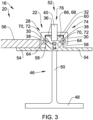
Fig. 3 depicts a cross-section of the first embodiment; -
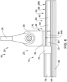
Fig. 4 depicts a partial longitudinal section of a second embodiment of a rail mounting arrangement; -
Fig. 5 depicts a partial longitudinal section of a variant of the second embodiment; -
Fig. 6 depicts a partial longitudinal section of a third embodiment of a rail mounting arrangement; -
Fig. 7 depicts a cross-section of the third embodiment; -
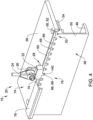
Fig. 8 depicts a partial longitudinal section of a fourth embodiment of a rail mounting arrangement; -
Fig. 9 depicts side-by side view of a fifth embodiment of a rail mounting arrangement; and -
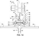
Fig. 10 depicts a partial cross-section of a sixth embodiment of a rail mounting arrangement. - Referring to
Fig. 1 , anaircraft 10 includes anaircraft cabin 12. In a manner known per se, theaircraft cabin 12 includes a plurality ofcabin components 14 that are mounted to afloor portion 16. Examples forcabin components 14 include, but are not limited to, cabin monuments such as galleys and lavatories, passenger seats, and other floor-mounted components. - The
cabin components 14 are mounted to thefloor portion 16 by arail mounting arrangement 20. - Referring to
Fig. 2 and3 , therail mounting arrangement 20 is depicted in more detail. Therail mounting arrangement 20 comprises a mountingmember 22. The mountingmember 22 may include a mountingstrut 24 that is connected to the cabin component 14 (not shown). The mountingstrut 24 can pivot so as to form an angle between 0 degrees and 90 degrees relative to thehorizontal floor portion 16. - The mounting
member 22 preferably supports the mountingstrut 24 on at least oneflange portion 26. - The mounting
member 22 further comprises a mountingsection 28. The mountingsection 28 preferably has C-shaped cross-section. The mountingsection 28 includes a pair oflateral legs 30 that extend in a vertical direction. The mountingsection 28 further comprises abase portion 32 that extends in the horizontal direction. Thelateral legs 30 protrude from thebase portion 32 downward. - Each
lateral leg 30 preferably includes an innerlateral side portion 34 that is arranged to face towards a mountingchannel 36 that is defined by the mountingsection 28. The innerlateral side portion 34 may include aninner locking groove 38 that is open towards the mountingchannel 36. - The mounting
member 22 includes a securingpin 40. The securingpin 40 is arranged such that in a retracted position the securingpin 40 is flush or recessed with respect to the mountingchannel 36. In other words, the mountingchannel 36 is unobstructed when viewed along its longitudinal direction. The securingpin 40 can be moved into an extended position, in which the securingpin 40 protrudes from thebase portion 32 into the mountingchannel 36. - The mounting
member 22 may include a securinglever 42. The securinglever 42 is rotatably supported by the mountingmember 22. The securinglever 42 includes a cam portion that is configured so as to displace the securingpin 40 from the retracted position into the extended position. - The mounting
member 22 may include anelastic member 44 that is arranged so as to press the securingpin 40 against the securinglever 42, specifically the cam portion. - The
rail mounting arrangement 20 further comprises a mountingrail 46 that extends in a longitudinal direction. The mountingrail 46 has asupport base 48 that extends in a horizontal direction. Thesupport base 48 is typically in contact with a lower part of thefloor portion 16 of theaircraft cabin 12. - The mounting
rail 46 may further comprise avertical support 50 that protrudes from thesupport base 48 upward. - The mounting
rail 46 further includes a mountingprofile portion 52. The mountingprofile portion 52 may comprise afloor board support 54. Thefloor board support 54 supports a plurality offloor boards 56 that form the cabin floor of theaircraft cabin 12. The mountingprofile portion 52 is configured for mounting the mountingmember 22. Preferably, the mountingprofile portion 52 is shaped so as to match the mountingsection 28. The mountingprofile portion 52 is preferably configured in a manner which allows the mountingprofile portion 52 to be received inside the mountingchannel 36. - The mounting
profile portion 52 preferably includes a pair of outerlateral side portions 58. Each outerlateral side portion 58 preferably extends in a vertical direction and, when the mountingmember 22 is installed, faces the mountingmember 22, preferably the respective innerlateral side portions 34. - The mounting
profile portion 52 may further include atop side portion 60. Thetop side portion 60 extends in a horizontal direction and along the longitudinal direction. Thetop side portion 60 is preferably arranged in between the outerlateral side portions 58. Together, the outerlateral side portions 58 and thetop side portion 60 may be considered as outward facing surfaces. - Each outer
lateral side portion 58 may include anouter locking groove 62. Theouter locking groove 62 is arranged such that it faces theinner locking groove 38. The inner andouter locking grooves disengagement locking channel 64. Thedisengagement locking channel 64 preferably has a circular or ellipsoidal cross-section. - The
top side portion 60 may include a plurality of securingholes 66, which act as securingrecesses 68. Each securingrecess 68 is recessed from the surface of thetop side portion 60 into the mountingprofile section 52. The securing recesses 68 are shaped such that they can receive the securingpin 40 in a form-fitting manner. - The
rail mounting arrangement 20 may further include adisengagement locking member 70. Thedisengagement locking member 70 preferably includes at least onedisengagement locking pin 72. Thedisengagement locking member 70 is configured to be received in thedisengagement locking channel 64. Preferably, thedisengagement locking pin 72 has the same cross-section as thedisengagement locking channel 64. - Subsequently, a mounting procedure for mounting the mounting
member 22 to the mountingrail 46 is described in more detail. - Initially, the mounting
member 22 and the mountingrail 46 are separate from each other. The mountingmember 22 may be attached to a passenger seat, for example. - The mounting
member 22 is arranged such that the mountingprofile portion 52 engages the mountingmember 22. Preferably, the mountingprofile portion 52 is surrounded on three sides, when viewed in a cross-section, by the mountingsection 28. Preferably, the mountingprofile portion 52 is received in the mountingchannel 36. - The
disengagement locking member 70 is inserted into thedisengagement locking channel 64. In this configuration, the mountingmember 22 may still slide along the longitudinal direction of the mountingrail 46 supported by the mountingprofile portion 52. However, when thedisengagement locking member 70 is inserted into thedisengagement locking channels 64, the mountingmember 22 is blocked from being removed in the vertical transversal direction of the mountingrail 46. Thedisengagement locking member 70 and the inner andouter locking groove disengagement locking mechanism 74. Consequently, in the aforementioned configuration, thedisengagement locking mechanism 74 prevents the mountingmember 22 from being removed from the mountingprofile portion 52 in the vertical direction, while still being moveable along the longitudinal direction of the mountingrail 46. - The mounting
member 22 is slid along the mountingrail 46 until it reaches the desired location. - A user may operate the securing
lever 42 so as to push the securingpin 40 from the retracted position into the extend position. The securingpin 40 is received in the securingrecess 68 and prevents movement of the mountingmember 22 along the longitudinal direction in a form-fitting manner. The securingpin 40 is an example of a securing protrusion. This securing protrusion and the securingrecess 68 form asecuring mechanism 76. In the configuration, when the securingpin 40 and the securingrecess 68 engage, the securingmechanism 76 is in an engaged state. In the engaged state, the securingmechanism 76 prevents the mountingmember 22 from being moved along the mountingrail 46 along the longitudinal direction. - In this configuration, the
disengagement locking mechanism 74 and thesecuring mechanism 76 are separate mechanisms. It is therefore possible for thedisengagement locking mechanism 74 to be in a locked state while the securingmechanism 76 in a disengaged state. - For sake of brevity, further embodiments of the invention are only described in so far as they differ from previously described embodiments.
- Referring to
Fig. 4 , the mountingmember 22 includes a fixed securingpin 140. The fixedsecuring pin 140 protrudes from thebase portion 32 into the mountingchannel 36. - Referring to
Fig. 5 , the mountingmember 22 is configured with the fixed securingpin 140 and a second fixed securingpin 142. - As depicted in both
Fig. 4 andFig. 5 , therail mounting arrangement 20 may include arail cover 78, which is arranged to cover the unused sections of the mountingprofile portion 52. - In the second embodiment and its variant according to
Fig. 4 andFig. 5 , the fixed securingpin 140 and as the case may be the second fixed securingpin 142 together with the securing recesses 68 form a securing mechanism 176. - Subsequently, the mounting process for the mounting
member 22 to the mountingrail 46 is described. - Similarly to the first embodiment, initially the mounting
member 22 and the mountingrail 46 are separate from each other. However, due to the configuration of the securingmechanism 76, the mountingmember 22 is positioned at the desired location, by inserting the fixed securingpin 140 and if applicable, the second fixed securingpin 142 into the securing recesses 68. In this configuration, the securingmechanism 76 is considered to be in an engaged state, since the mountingmember 22 cannot be moved along the longitudinal direction of the mountingrail 46 due to the securing pins 140, 142 engaging the mountingprofile portion 52 in a form-fitting manner. - The
disengagement locking member 70 is inserted in to thedisengagement locking channel 64, whereby the mountingmember 22 is prevented from being removed along a vertical direction from the mountingprofile portion 52. - As a result, the mounting
member 22 is fixed in location and thecabin component 14 that is supported by the mountingmember 22 is attached to thefloor portion 16. - Referring to
Fig. 6 andFig. 7 , the mountingmember 22 comprises atoothed portion 240, wherein the protruding teeth form securing protrusions. - The
top side portion 60 also includes atoothed portion 266, wherein the indentations act as securing recesses. - The installation (and removal) is identical to the second embodiment.
- Referring to
Fig. 8 , the mountingmember 22 has aflat base portion 332, whereas the mountingprofile portion 52, specifically thetop side portion 60 includes thetoothed portion 266. - The
rail mounting arrangement 20 further includes a securingmember 340 that has formed on it atooth portion 342. The mountingmember 22 includes aninsertion opening 344 that is configured to receive the securingmember 340. - Furthermore, the mounting
member 22 may include aspring detent 80 that is arranged to engage thedisengagement locking member 70, when it is inserted in thedisengagement locking channel 64. - Similarly to the first embodiment, the mounting
member 22 may engage the mountingprofile portion 52 in a sliding manner. When thedisengagement locking member 70 is inserted in thedisengagement locking channel 64, the mountingmember 22 can no longer be removed from the mountingrail 46 along the vertical direction. However, the mountingmember 22 may still slide along the longitudinal direction. When the mountingmember 22 is at the desired location, the securingmember 342 is inserted into theinsertion opening 344. Thetoothed portion 342 measures with thetoothed portion 266 thereby preventing a movement of the mountingmember 22 along the longitudinal direction. - It should be noted that in this embodiment the securing
member 340 is part of the securingmechanism 76. - Referring to
Fig. 9 , a fifth embodiment of therail mounting arrangement 20 is illustrated wherein the left depicts the securingmechanism 76 in a disengaged state, whereas the right portion of the drawing depicts the securingmechanism 76 in an engaged state. - In this embodiment the mounting
member 22 comprises a securingbolt 440. The securingbolt 440 is supported in a rotatable manner and includes atoothed portion 442. Furthermore, the securingbolt 440 includes aflat portion 444. The mounting process is similar to the first embodiment. Initially, the mountingmember 22 may be attached to the mountingprofile portion 52 in a sliding manner by inserting thedisengagement locking member 70 into thedisengagement locking channel 64. In this situation the securingbolt 440 is turned in such a way that theflat portion 444 faces the mountingprofile portion 52. The mountingmember 22 is thus able to slide along the longitudinal direction. - When the mounting
member 22 is at the desired location, the securingbolt 440 is turned such that thetooth portion 442 meshes with thetoothed portion 266. As a result, the mountingmember 22 is now locked in place. - Referring to
Fig. 10 , therail mounting arrangement 20 is similar to the fifth embodiment; however, it should be noted that the configuration described herein is also applicable to all other embodiments. - In this embodiment, the mounting
rail 46 is made from aluminum or fiber-reinforced plastic. The mountingprofile portion 52, in contrast to the other embodiments, is made as a separate member out of a lightweight metallic material, preferably titanium. The mountingprofile portion 52 otherwise comprises all the necessary features for implementing any of the previously described embodiments. The mountingprofile portion 52 is riveted to the mountingrail 46, wherein therivets 82 are horizontally aligned and engage with the outerlateral side portions 58. - In order to improve rail mounting arrangements in vehicles, preferably in aircraft, the invention proposes a mounting member (22), that is configured to support a cabin component (14) to be mounted to a mounting rail (46). The rail mounting arrangement (20) comprises a disengagement locking mechanism (74) that prevents a removal of the mounting member (22) along a transversal direction of the mounting rail (46), while still allowing movement along the longitudinal direction. The rail mounting arrangement (20) includes a securing mechanism (76) that is configured to secure the mounting member (22) at the desired location along the mounting rail (46).
-
- 10
- aircraft
- 12
- aircraft cabin
- 14
- cabin component
- 16
- floor portion
- 20
- rail mounting arrangement
- 22
- mounting member
- 24
- mounting strut
- 26
- flange portion
- 28
- mounting section
- 30
- lateral leg
- 32
- base portion
- 34
- inner lateral side portion
- 36
- mounting channel
- 38
- inner locking groove
- 40
- securing pin
- 42
- securing lever
- 44
- elastic member
- 46
- mounting rail
- 48
- support base
- 50
- vertical support
- 52
- mounting profile portion
- 54
- floor board support
- 56
- floor board
- 58
- outer lateral side portion
- 60
- top side portion
- 62
- outer locking groove
- 64
- disengagement locking channel
- 66
- securing hole
- 68
- securing recess
- 70
- disengagement locking member
- 72
- disengagement locking pin
- 74
- disengagement locking mechanism
- 76
- securing mechanism
- 78
- rail cover
- 80
- spring detent
- 82
- rivet
- 140
- fixed securing pin
- 142
- second fixed securing pin
- 240
- toothed portion
- 266
- toothed portion
- 332
- base portion
- 340
- securing member
- 342
- toothed portion
- 344
- insertion opening
- 440
- securing bolt
- 442
- toothed portion
- 444
- flat portion
Claims (15)
- A rail mounting arrangement (20) for a vehicle, preferably for an aircraft (10), the arrangement (20) comprising:- a mounting member (22) that is configured to support a cabin component (14), such as a seat;- a mounting rail (46) that extends in a longitudinal direction and that has a mounting profile portion (52) that is configured for mounting the mounting member (22);wherein the rail mounting arrangement (20) includes a disengagement locking mechanism (74) that is partially provided on the mounting member (22) and on the mounting profile portion (52), respectively, wherein the disengagement locking mechanism (74) includes a disengagement locking member (70) that, when the disengagement locking member (70) engages the mounting member (22) and the mounting profile portion (52), prevents removal of the mounting member (22) in a transversal direction of the mounting rail (46), and that, when the disengagement locking member is (70) disengaged from the mounting member (22) and the mounting rail (46), allows removal of the mounting member (22) from the mounting rail (46),wherein the rail mounting arrangement (20) includes a securing mechanism (76) that is partially provided on the mounting member (22) and on the mounting profile portion (52), respectively, wherein the securing mechanism (76) includes a first vertical locking portion that is arranged on the mounting member (22) so as to face the mounting profile portion (52) and a second vertical locking portion that is arranged on the mounting profile portion (52) so as to face the mounting member (22),wherein the first vertical locking portion and the second vertical locking portion are matched such that, when the securing mechanism (76) is in a locked state, the first and second vertical locking portions engage each other in a form-fitting manner such that a movement of the mounting member (22) relative to the mounting rail (46) along the longitudinal direction is blocked.
- The arrangement (20) according to claim 1, wherein the mounting profile portion (52) includes at least one outer lateral side portion (58) that faces outward towards the mounting member (22), and the disengagement locking mechanism (74) is partially provided on the at least one outer lateral side portion (58).
- The arrangement (20) according to any of the preceding claims, wherein the mounting member (22) includes at least one inner lateral side portion (34) that faces inward towards the mounting profile portion (52), and the disengagement locking mechanism (74) is partially provided on the at least one inner lateral side portion (34).
- The arrangement (20) according to any of the preceding claims, wherein the disengagement locking mechanism (74) includes at least one outer locking groove (62) that is formed on the mounting profile portion (52) and a corresponding number of inner locking grooves (38) that are formed on the mounting member (22), wherein preferably the outer locking groove (62) is arranged on the outer lateral side portion (58) and the inner locking groove (38) is arranged on the inner lateral side portion (34).
- The arrangement (20) according to any of the preceding claims, wherein the mounting profile portion (52) includes a top side portion (60) that faces upward towards the mounting member (22) and extends in a horizontal direction, and the securing mechanism (76) is partially provided on the top side portion (60).
- The arrangement (20) according to any of the preceding claims, wherein the mounting member (22) includes a bottom side portion that faces downward towards the mounting profile portion (52) and extends in a horizontal direction, and the securing mechanism (76) is partially provided on the bottom side portion.
- The arrangement (20) according to any of the preceding claims, wherein the securing mechanism (76) includes a plurality or securing recesses that are formed on the mounting rail (46) and are recessed into the mounting profile portion (52) and includes at least one securing protrusion that protrudes from the mounting member (22) in vertical direction towards the mounting rail (46) and, when the securing mechanism (76) is in a secured state, into the mounting recesses.
- The arrangement (20) according to claim 7, wherein the securing recesses (68) and the securing protrusions are both formed as matching toothed portions (240, 266) that, when the securing mechanism (76) is in a secured state, mesh with each other.
- The arrangement (20) according to claim 7 or 8, wherein the securing mechanism (76) comprises a securing member that is insertable between the mounting member (22) and the mounting profile portion (52) and comprises a toothed portion (240, 266) that, when the securing member is inserted and the securing mechanism (76) is in a secured state, meshes with the toothed portion of the mounting profile portion (52).
- The arrangement (20) according to claim 7 or 8, wherein the securing mechanism (76) includes a rotatable securing bolt (440) that is rotatable about an axis that is parallel to the longitudinal direction and includes a toothed portion (240, 266) that, when the securing mechanism (76) is in a secured state, meshes with the toothed portion (240, 266) of the mounting profile portion (52).
- The arrangement (20) according to claim 7, wherein the plurality of securing recesses (68) is formed as a series of securing holes (66) that are drilled in a vertical direction into the mounting profile portion (52), and the at least one securing protrusion is formed as a securing pin (40) that extends in the vertical direction and, when the securing mechanism (76) is in a secured state, is received a securing hole (66).
- The arrangement (20) according to claim 7 or 11, wherein the securing protrusion or the securing pin (40) is movable along the vertical direction between an unsecured state and a secured state via a toolless moving mechanism.
- The arrangement (20) according to any of the preceding claims, wherein the mounting rail (46) comprises a support portion made from a fiber reinforced plastic material or a metal material and the mounting profile portion (52) is made from a metal material that is different from the metal material of the support portion, wherein the mounting profile portion (52) is attached to the support portion, preferably by rivets (82) that are aligned in a transversal direction of the mounting rail (46).
- The arrangement (20) according to any of the preceding claims, wherein the disengagement locking mechanism (74) is configured such that, when the disengagement locking member (74) is installed, the securing mechanism (76) is forced into the secured state and movement of the mounting member (22) is blocked.
- An aircraft (10) or aircraft cabin (12) including a floor portion (16) and an arrangement (20) according to any of the preceding claims, wherein a cabin component (14) is removably attached to the floor portion (16) via the arrangement (20).
Priority Applications (3)
| Application Number | Priority Date | Filing Date | Title |
|---|---|---|---|
| EP22179897.8A EP4296164B1 (en) | 2022-06-20 | 2022-06-20 | A rail mounting arrangement for a vehicle, such as an aircraft, and a vehicle equipped with said arrangement |
| US18/329,658 US12286232B2 (en) | 2022-06-20 | 2023-06-06 | Rail mounting arrangement for a vehicle, such as an aircraft, and a vehicle equipped with said arrangement |
| CN202310715465.4A CN117262219A (en) | 2022-06-20 | 2023-06-16 | Guide rail mounting device and aircraft or aircraft cabin |
Applications Claiming Priority (1)
| Application Number | Priority Date | Filing Date | Title |
|---|---|---|---|
| EP22179897.8A EP4296164B1 (en) | 2022-06-20 | 2022-06-20 | A rail mounting arrangement for a vehicle, such as an aircraft, and a vehicle equipped with said arrangement |
Publications (2)
| Publication Number | Publication Date |
|---|---|
| EP4296164A1 true EP4296164A1 (en) | 2023-12-27 |
| EP4296164B1 EP4296164B1 (en) | 2025-04-02 |
Family
ID=82117280
Family Applications (1)
| Application Number | Title | Priority Date | Filing Date |
|---|---|---|---|
| EP22179897.8A Active EP4296164B1 (en) | 2022-06-20 | 2022-06-20 | A rail mounting arrangement for a vehicle, such as an aircraft, and a vehicle equipped with said arrangement |
Country Status (3)
| Country | Link |
|---|---|
| US (1) | US12286232B2 (en) |
| EP (1) | EP4296164B1 (en) |
| CN (1) | CN117262219A (en) |
Families Citing this family (1)
| Publication number | Priority date | Publication date | Assignee | Title |
|---|---|---|---|---|
| EP4610163A1 (en) * | 2024-02-28 | 2025-09-03 | Airbus Operations GmbH | Floor assembly and aircraft with monolithic floor element |
Citations (8)
| Publication number | Priority date | Publication date | Assignee | Title |
|---|---|---|---|---|
| US2655981A (en) * | 1950-06-16 | 1953-10-20 | John C Whittingham | Adjustable pilot chair |
| US3381927A (en) * | 1966-09-27 | 1968-05-07 | Universal Oil Prod Co | Track attachment means for seats and the like |
| DE102009028533A1 (en) | 2009-08-14 | 2011-02-17 | Airbus Operations Gmbh | Fastening system for guiding in pre-determined guide direction and detachable fastening of module in space craft and air craft, has guide rail which has guiding device stretching in guide direction and cross-section device with head section |
| DE102009028534A1 (en) * | 2009-08-14 | 2011-02-17 | Airbus Operations Gmbh | Fastening system for guiding in pre-determined guiding direction and detachable fastening of module, particularly seat, in aircraft and spacecraft, has guide rail that extends in guiding direction and has guiding mechanism |
| DE102009028903A1 (en) | 2009-08-26 | 2011-03-10 | Airbus Operations Gmbh | Mounting system in an aircraft and spacecraft |
| DE102010053892A1 (en) | 2010-12-09 | 2012-06-14 | Airbus Operations Gmbh | Seat adjustment device as well as aircraft or spacecraft |
| US20190308736A1 (en) * | 2018-04-06 | 2019-10-10 | Airbus Operations Gmbh | Fastening System For Passenger Seats In A Cabin Of A Vehicle |
| DE102018122958A1 (en) | 2018-09-19 | 2020-03-19 | Airbus Operations Gmbh | Floor mounting assembly |
Family Cites Families (4)
| Publication number | Priority date | Publication date | Assignee | Title |
|---|---|---|---|---|
| US8998323B2 (en) * | 2012-08-09 | 2015-04-07 | Ami Industries, Inc. | Warped-floor tolerant aircraft seat |
| DE102015116414A1 (en) * | 2015-09-28 | 2017-03-30 | Airbus Operations Gmbh | Passenger seating system with sliding seats for a means of transport and an aircraft cabin with such a passenger seat system |
| DE102018118345A1 (en) * | 2018-07-30 | 2020-01-30 | Airbus Operations Gmbh | Fastening system for passenger seats in a cabin of a vehicle |
| JP7345294B2 (en) * | 2019-07-02 | 2023-09-15 | Thk株式会社 | Changing the seating arrangement in the cabin |
-
2022
- 2022-06-20 EP EP22179897.8A patent/EP4296164B1/en active Active
-
2023
- 2023-06-06 US US18/329,658 patent/US12286232B2/en active Active
- 2023-06-16 CN CN202310715465.4A patent/CN117262219A/en active Pending
Patent Citations (8)
| Publication number | Priority date | Publication date | Assignee | Title |
|---|---|---|---|---|
| US2655981A (en) * | 1950-06-16 | 1953-10-20 | John C Whittingham | Adjustable pilot chair |
| US3381927A (en) * | 1966-09-27 | 1968-05-07 | Universal Oil Prod Co | Track attachment means for seats and the like |
| DE102009028533A1 (en) | 2009-08-14 | 2011-02-17 | Airbus Operations Gmbh | Fastening system for guiding in pre-determined guide direction and detachable fastening of module in space craft and air craft, has guide rail which has guiding device stretching in guide direction and cross-section device with head section |
| DE102009028534A1 (en) * | 2009-08-14 | 2011-02-17 | Airbus Operations Gmbh | Fastening system for guiding in pre-determined guiding direction and detachable fastening of module, particularly seat, in aircraft and spacecraft, has guide rail that extends in guiding direction and has guiding mechanism |
| DE102009028903A1 (en) | 2009-08-26 | 2011-03-10 | Airbus Operations Gmbh | Mounting system in an aircraft and spacecraft |
| DE102010053892A1 (en) | 2010-12-09 | 2012-06-14 | Airbus Operations Gmbh | Seat adjustment device as well as aircraft or spacecraft |
| US20190308736A1 (en) * | 2018-04-06 | 2019-10-10 | Airbus Operations Gmbh | Fastening System For Passenger Seats In A Cabin Of A Vehicle |
| DE102018122958A1 (en) | 2018-09-19 | 2020-03-19 | Airbus Operations Gmbh | Floor mounting assembly |
Non-Patent Citations (3)
| Title |
|---|
| ALLSAFE GMBH & CO.KG: "ATD-System der allsafe GmbH & Co.KG", ATD-SYSTEM, 1 January 2019 (2019-01-01), pages 1 - 152, XP093137305 |
| ALLSAFE GMBH & CO.KG: "CRS-System", ALLSAFE GMBH & CO.KG, 1 January 2017 (2017-01-01), pages 1 - 14, XP093137310, [retrieved on 20240304] |
| ALLSAFE GMBH & CO.KG: "TranSAFE carrier-System ", ALLSAFE GMBH & CO.KG, 1 January 2021 (2021-01-01), pages 1 - 12, XP093137307 |
Also Published As
| Publication number | Publication date |
|---|---|
| US20230406513A1 (en) | 2023-12-21 |
| CN117262219A (en) | 2023-12-22 |
| EP4296164B1 (en) | 2025-04-02 |
| US12286232B2 (en) | 2025-04-29 |
Similar Documents
| Publication | Publication Date | Title |
|---|---|---|
| US8899545B2 (en) | Apparatus for affixing an object to a rail | |
| US12286232B2 (en) | Rail mounting arrangement for a vehicle, such as an aircraft, and a vehicle equipped with said arrangement | |
| CN103282238B (en) | Fixed system | |
| CN108136936A (en) | The method of guide rail adapter system and the base plate rail installed adapter into the vehicles | |
| CN101573259A (en) | Shoulder adjuster device | |
| US7429090B2 (en) | Attachment device for drawer front panels | |
| CN108290509B (en) | Seat depth adjuster | |
| KR101676596B1 (en) | Roof Carrier for Car | |
| CN111093433B (en) | Coupling device with subsequent latching | |
| EP3653451A1 (en) | Anchor position adjustment device | |
| CN107429728B (en) | For causing the attachment device of tolerance by manufacturing and/or assembling between compensation member | |
| US20220314841A1 (en) | Locking apparatus of seat rail for vehicle | |
| US20020084683A1 (en) | Automatic seat mounting arrangement and seat track assembly | |
| KR20180123239A (en) | Sunvisor of vehicles | |
| US12508957B2 (en) | Locking device for a vehicle seat, comprising a securing section that secures a locking element in a locking position in a positive manner | |
| EP2062815B1 (en) | Airplane seat track | |
| EP2771237B1 (en) | Fastening arrangement for plate-shaped facing components | |
| US5704524A (en) | Latch actuator for automoblie article carriers | |
| JP2016030520A (en) | Vehicle slide rail device | |
| JP2015116950A (en) | Seat back structure of vehicle seat | |
| KR20040074790A (en) | Long-slider type seat-track locking device for vehicles | |
| US8496220B2 (en) | Fixing system for a seat, for example an aircraft seat | |
| DE102006002556B3 (en) | Connecting element for vehicle body, has connecting areas and fixing area, formed for connecting rails as well as fixing these rails at body of vehicle | |
| CN114851927B (en) | Child safety seat and ISOFIX telescopic adjustment mechanism thereof | |
| JP7757105B2 (en) | Railway vehicle and its manufacturing method |
Legal Events
| Date | Code | Title | Description |
|---|---|---|---|
| PUAI | Public reference made under article 153(3) epc to a published international application that has entered the european phase |
Free format text: ORIGINAL CODE: 0009012 |
|
| STAA | Information on the status of an ep patent application or granted ep patent |
Free format text: STATUS: THE APPLICATION HAS BEEN PUBLISHED |
|
| AK | Designated contracting states |
Kind code of ref document: A1 Designated state(s): AL AT BE BG CH CY CZ DE DK EE ES FI FR GB GR HR HU IE IS IT LI LT LU LV MC MK MT NL NO PL PT RO RS SE SI SK SM TR |
|
| TPAC | Observations filed by third parties |
Free format text: ORIGINAL CODE: EPIDOSNTIPA |
|
| STAA | Information on the status of an ep patent application or granted ep patent |
Free format text: STATUS: REQUEST FOR EXAMINATION WAS MADE |
|
| 17P | Request for examination filed |
Effective date: 20240627 |
|
| RBV | Designated contracting states (corrected) |
Designated state(s): AL AT BE BG CH CY CZ DE DK EE ES FI FR GB GR HR HU IE IS IT LI LT LU LV MC MK MT NL NO PL PT RO RS SE SI SK SM TR |
|
| REG | Reference to a national code |
Ref country code: DE Ref legal event code: R079 Free format text: PREVIOUS MAIN CLASS: B64D0011000000 Ipc: B64D0011060000 Ref document number: 602022012471 Country of ref document: DE |
|
| GRAP | Despatch of communication of intention to grant a patent |
Free format text: ORIGINAL CODE: EPIDOSNIGR1 |
|
| RIC1 | Information provided on ipc code assigned before grant |
Ipc: B64D 11/06 20060101AFI20240918BHEP |
|
| STAA | Information on the status of an ep patent application or granted ep patent |
Free format text: STATUS: GRANT OF PATENT IS INTENDED |
|
| INTG | Intention to grant announced |
Effective date: 20241024 |
|
| GRAS | Grant fee paid |
Free format text: ORIGINAL CODE: EPIDOSNIGR3 |
|
| GRAA | (expected) grant |
Free format text: ORIGINAL CODE: 0009210 |
|
| STAA | Information on the status of an ep patent application or granted ep patent |
Free format text: STATUS: THE PATENT HAS BEEN GRANTED |
|
| AK | Designated contracting states |
Kind code of ref document: B1 Designated state(s): AL AT BE BG CH CY CZ DE DK EE ES FI FR GB GR HR HU IE IS IT LI LT LU LV MC MK MT NL NO PL PT RO RS SE SI SK SM TR |
|
| REG | Reference to a national code |
Ref country code: GB Ref legal event code: FG4D |
|
| REG | Reference to a national code |
Ref country code: CH Ref legal event code: EP |
|
| REG | Reference to a national code |
Ref country code: DE Ref legal event code: R096 Ref document number: 602022012471 Country of ref document: DE |
|
| REG | Reference to a national code |
Ref country code: IE Ref legal event code: FG4D |
|
| PGFP | Annual fee paid to national office [announced via postgrant information from national office to epo] |
Ref country code: DE Payment date: 20250618 Year of fee payment: 4 |
|
| PGFP | Annual fee paid to national office [announced via postgrant information from national office to epo] |
Ref country code: FR Payment date: 20250627 Year of fee payment: 4 |
|
| PGFP | Annual fee paid to national office [announced via postgrant information from national office to epo] |
Ref country code: AT Payment date: 20250721 Year of fee payment: 4 |
|
| REG | Reference to a national code |
Ref country code: NL Ref legal event code: MP Effective date: 20250402 |
|
| PG25 | Lapsed in a contracting state [announced via postgrant information from national office to epo] |
Ref country code: NL Free format text: LAPSE BECAUSE OF FAILURE TO SUBMIT A TRANSLATION OF THE DESCRIPTION OR TO PAY THE FEE WITHIN THE PRESCRIBED TIME-LIMIT Effective date: 20250402 |
|
| REG | Reference to a national code |
Ref country code: AT Ref legal event code: MK05 Ref document number: 1781101 Country of ref document: AT Kind code of ref document: T Effective date: 20250402 |
|
| PG25 | Lapsed in a contracting state [announced via postgrant information from national office to epo] |
Ref country code: PT Free format text: LAPSE BECAUSE OF FAILURE TO SUBMIT A TRANSLATION OF THE DESCRIPTION OR TO PAY THE FEE WITHIN THE PRESCRIBED TIME-LIMIT Effective date: 20250804 Ref country code: FI Free format text: LAPSE BECAUSE OF FAILURE TO SUBMIT A TRANSLATION OF THE DESCRIPTION OR TO PAY THE FEE WITHIN THE PRESCRIBED TIME-LIMIT Effective date: 20250402 Ref country code: ES Free format text: LAPSE BECAUSE OF FAILURE TO SUBMIT A TRANSLATION OF THE DESCRIPTION OR TO PAY THE FEE WITHIN THE PRESCRIBED TIME-LIMIT Effective date: 20250402 |
|
| REG | Reference to a national code |
Ref country code: LT Ref legal event code: MG9D |
|
| PG25 | Lapsed in a contracting state [announced via postgrant information from national office to epo] |
Ref country code: GR Free format text: LAPSE BECAUSE OF FAILURE TO SUBMIT A TRANSLATION OF THE DESCRIPTION OR TO PAY THE FEE WITHIN THE PRESCRIBED TIME-LIMIT Effective date: 20250703 Ref country code: NO Free format text: LAPSE BECAUSE OF FAILURE TO SUBMIT A TRANSLATION OF THE DESCRIPTION OR TO PAY THE FEE WITHIN THE PRESCRIBED TIME-LIMIT Effective date: 20250702 |
|
| PG25 | Lapsed in a contracting state [announced via postgrant information from national office to epo] |
Ref country code: PL Free format text: LAPSE BECAUSE OF FAILURE TO SUBMIT A TRANSLATION OF THE DESCRIPTION OR TO PAY THE FEE WITHIN THE PRESCRIBED TIME-LIMIT Effective date: 20250402 |
|
| PG25 | Lapsed in a contracting state [announced via postgrant information from national office to epo] |
Ref country code: BG Free format text: LAPSE BECAUSE OF FAILURE TO SUBMIT A TRANSLATION OF THE DESCRIPTION OR TO PAY THE FEE WITHIN THE PRESCRIBED TIME-LIMIT Effective date: 20250402 |
|
| PG25 | Lapsed in a contracting state [announced via postgrant information from national office to epo] |
Ref country code: AT Free format text: LAPSE BECAUSE OF FAILURE TO SUBMIT A TRANSLATION OF THE DESCRIPTION OR TO PAY THE FEE WITHIN THE PRESCRIBED TIME-LIMIT Effective date: 20250402 Ref country code: HR Free format text: LAPSE BECAUSE OF FAILURE TO SUBMIT A TRANSLATION OF THE DESCRIPTION OR TO PAY THE FEE WITHIN THE PRESCRIBED TIME-LIMIT Effective date: 20250402 |
|
| PG25 | Lapsed in a contracting state [announced via postgrant information from national office to epo] |
Ref country code: RS Free format text: LAPSE BECAUSE OF FAILURE TO SUBMIT A TRANSLATION OF THE DESCRIPTION OR TO PAY THE FEE WITHIN THE PRESCRIBED TIME-LIMIT Effective date: 20250702 |
|
| PG25 | Lapsed in a contracting state [announced via postgrant information from national office to epo] |
Ref country code: IS Free format text: LAPSE BECAUSE OF FAILURE TO SUBMIT A TRANSLATION OF THE DESCRIPTION OR TO PAY THE FEE WITHIN THE PRESCRIBED TIME-LIMIT Effective date: 20250802 |
|
| PG25 | Lapsed in a contracting state [announced via postgrant information from national office to epo] |
Ref country code: LV Free format text: LAPSE BECAUSE OF FAILURE TO SUBMIT A TRANSLATION OF THE DESCRIPTION OR TO PAY THE FEE WITHIN THE PRESCRIBED TIME-LIMIT Effective date: 20250402 |
|
| REG | Reference to a national code |
Ref country code: DE Ref legal event code: R097 Ref document number: 602022012471 Country of ref document: DE |
|
| PG25 | Lapsed in a contracting state [announced via postgrant information from national office to epo] |
Ref country code: SM Free format text: LAPSE BECAUSE OF FAILURE TO SUBMIT A TRANSLATION OF THE DESCRIPTION OR TO PAY THE FEE WITHIN THE PRESCRIBED TIME-LIMIT Effective date: 20250402 Ref country code: DK Free format text: LAPSE BECAUSE OF FAILURE TO SUBMIT A TRANSLATION OF THE DESCRIPTION OR TO PAY THE FEE WITHIN THE PRESCRIBED TIME-LIMIT Effective date: 20250402 |
|
| PG25 | Lapsed in a contracting state [announced via postgrant information from national office to epo] |
Ref country code: CZ Free format text: LAPSE BECAUSE OF FAILURE TO SUBMIT A TRANSLATION OF THE DESCRIPTION OR TO PAY THE FEE WITHIN THE PRESCRIBED TIME-LIMIT Effective date: 20250402 |
|
| PG25 | Lapsed in a contracting state [announced via postgrant information from national office to epo] |
Ref country code: EE Free format text: LAPSE BECAUSE OF FAILURE TO SUBMIT A TRANSLATION OF THE DESCRIPTION OR TO PAY THE FEE WITHIN THE PRESCRIBED TIME-LIMIT Effective date: 20250402 |
|
| PG25 | Lapsed in a contracting state [announced via postgrant information from national office to epo] |
Ref country code: SK Free format text: LAPSE BECAUSE OF FAILURE TO SUBMIT A TRANSLATION OF THE DESCRIPTION OR TO PAY THE FEE WITHIN THE PRESCRIBED TIME-LIMIT Effective date: 20250402 |
|
| REG | Reference to a national code |
Ref country code: CH Ref legal event code: H13 Free format text: ST27 STATUS EVENT CODE: U-0-0-H10-H13 (AS PROVIDED BY THE NATIONAL OFFICE) Effective date: 20260127 |
|
| PG25 | Lapsed in a contracting state [announced via postgrant information from national office to epo] |
Ref country code: IT Free format text: LAPSE BECAUSE OF FAILURE TO SUBMIT A TRANSLATION OF THE DESCRIPTION OR TO PAY THE FEE WITHIN THE PRESCRIBED TIME-LIMIT Effective date: 20250402 |
|
| PG25 | Lapsed in a contracting state [announced via postgrant information from national office to epo] |
Ref country code: MC Free format text: LAPSE BECAUSE OF FAILURE TO SUBMIT A TRANSLATION OF THE DESCRIPTION OR TO PAY THE FEE WITHIN THE PRESCRIBED TIME-LIMIT Effective date: 20250402 |
|
| PLBE | No opposition filed within time limit |
Free format text: ORIGINAL CODE: 0009261 |
|
| STAA | Information on the status of an ep patent application or granted ep patent |
Free format text: STATUS: NO OPPOSITION FILED WITHIN TIME LIMIT |
|
| REG | Reference to a national code |
Ref country code: CH Ref legal event code: L10 Free format text: ST27 STATUS EVENT CODE: U-0-0-L10-L00 (AS PROVIDED BY THE NATIONAL OFFICE) Effective date: 20260211 |
|
| PG25 | Lapsed in a contracting state [announced via postgrant information from national office to epo] |
Ref country code: LU Free format text: LAPSE BECAUSE OF NON-PAYMENT OF DUE FEES Effective date: 20250620 |
|
| REG | Reference to a national code |
Ref country code: BE Ref legal event code: MM Effective date: 20250630 |
|
| PG25 | Lapsed in a contracting state [announced via postgrant information from national office to epo] |
Ref country code: RO Free format text: LAPSE BECAUSE OF FAILURE TO SUBMIT A TRANSLATION OF THE DESCRIPTION OR TO PAY THE FEE WITHIN THE PRESCRIBED TIME-LIMIT Effective date: 20250402 |
|
| 26N | No opposition filed |
Effective date: 20260105 |
|
| PG25 | Lapsed in a contracting state [announced via postgrant information from national office to epo] |
Ref country code: IE Free format text: LAPSE BECAUSE OF NON-PAYMENT OF DUE FEES Effective date: 20250620 |
|
| PG25 | Lapsed in a contracting state [announced via postgrant information from national office to epo] |
Ref country code: BE Free format text: LAPSE BECAUSE OF NON-PAYMENT OF DUE FEES Effective date: 20250630 |
|
| PG25 | Lapsed in a contracting state [announced via postgrant information from national office to epo] |
Ref country code: CH Free format text: LAPSE BECAUSE OF NON-PAYMENT OF DUE FEES Effective date: 20250630 |