EP4296144A1 - Work vehicle - Google Patents
Work vehicle Download PDFInfo
- Publication number
- EP4296144A1 EP4296144A1 EP23174543.1A EP23174543A EP4296144A1 EP 4296144 A1 EP4296144 A1 EP 4296144A1 EP 23174543 A EP23174543 A EP 23174543A EP 4296144 A1 EP4296144 A1 EP 4296144A1
- Authority
- EP
- European Patent Office
- Prior art keywords
- section
- rops
- guard section
- work vehicle
- oriented
- Prior art date
- Legal status (The legal status is an assumption and is not a legal conclusion. Google has not performed a legal analysis and makes no representation as to the accuracy of the status listed.)
- Pending
Links
Images







Classifications
-
- B—PERFORMING OPERATIONS; TRANSPORTING
- B62—LAND VEHICLES FOR TRAVELLING OTHERWISE THAN ON RAILS
- B62D—MOTOR VEHICLES; TRAILERS
- B62D25/00—Superstructure or monocoque structure sub-units; Parts or details thereof not otherwise provided for
- B62D25/08—Front or rear portions
- B62D25/082—Engine compartments
-
- B—PERFORMING OPERATIONS; TRANSPORTING
- B60—VEHICLES IN GENERAL
- B60K—ARRANGEMENT OR MOUNTING OF PROPULSION UNITS OR OF TRANSMISSIONS IN VEHICLES; ARRANGEMENT OR MOUNTING OF PLURAL DIVERSE PRIME-MOVERS IN VEHICLES; AUXILIARY DRIVES FOR VEHICLES; INSTRUMENTATION OR DASHBOARDS FOR VEHICLES; ARRANGEMENTS IN CONNECTION WITH COOLING, AIR INTAKE, GAS EXHAUST OR FUEL SUPPLY OF PROPULSION UNITS IN VEHICLES
- B60K13/00—Arrangement in connection with combustion air intake or gas exhaust of propulsion units
- B60K13/04—Arrangement in connection with combustion air intake or gas exhaust of propulsion units concerning exhaust
-
- B—PERFORMING OPERATIONS; TRANSPORTING
- B60—VEHICLES IN GENERAL
- B60R—VEHICLES, VEHICLE FITTINGS, OR VEHICLE PARTS, NOT OTHERWISE PROVIDED FOR
- B60R19/00—Wheel guards; Radiator guards, e.g. grilles; Obstruction removers; Fittings damping bouncing force in collisions
- B60R19/02—Bumpers, i.e. impact receiving or absorbing members for protecting vehicles or fending off blows from other vehicles or objects
- B60R19/24—Arrangements for mounting bumpers on vehicles
- B60R19/38—Arrangements for mounting bumpers on vehicles adjustably or movably mounted, e.g. horizontally displaceable for securing a space between parked vehicles
-
- B—PERFORMING OPERATIONS; TRANSPORTING
- B60—VEHICLES IN GENERAL
- B60R—VEHICLES, VEHICLE FITTINGS, OR VEHICLE PARTS, NOT OTHERWISE PROVIDED FOR
- B60R21/00—Arrangements or fittings on vehicles for protecting or preventing injuries to occupants or pedestrians in case of accidents or other traffic risks
- B60R21/02—Occupant safety arrangements or fittings, e.g. crash pads
- B60R21/13—Roll-over protection
- B60R21/131—Protective devices for drivers in case of overturning of tractors
-
- B—PERFORMING OPERATIONS; TRANSPORTING
- B62—LAND VEHICLES FOR TRAVELLING OTHERWISE THAN ON RAILS
- B62D—MOTOR VEHICLES; TRAILERS
- B62D25/00—Superstructure or monocoque structure sub-units; Parts or details thereof not otherwise provided for
- B62D25/08—Front or rear portions
- B62D25/10—Bonnets or lids, e.g. for trucks, tractors, busses, work vehicles
-
- B—PERFORMING OPERATIONS; TRANSPORTING
- B62—LAND VEHICLES FOR TRAVELLING OTHERWISE THAN ON RAILS
- B62D—MOTOR VEHICLES; TRAILERS
- B62D49/00—Tractors
- B62D49/06—Tractors adapted for multi-purpose use
-
- B—PERFORMING OPERATIONS; TRANSPORTING
- B62—LAND VEHICLES FOR TRAVELLING OTHERWISE THAN ON RAILS
- B62D—MOTOR VEHICLES; TRAILERS
- B62D49/00—Tractors
- B62D49/08—Tractors having means for preventing overturning or tipping
- B62D49/085—Counterweight
-
- B—PERFORMING OPERATIONS; TRANSPORTING
- B62—LAND VEHICLES FOR TRAVELLING OTHERWISE THAN ON RAILS
- B62D—MOTOR VEHICLES; TRAILERS
- B62D25/00—Superstructure or monocoque structure sub-units; Parts or details thereof not otherwise provided for
- B62D25/08—Front or rear portions
- B62D25/10—Bonnets or lids, e.g. for trucks, tractors, busses, work vehicles
- B62D25/12—Parts or details thereof
Definitions
- the present invention relates to a work vehicle in which an engine bonnet forming an engine compartment and a front guard covering a front portion of the engine bonnet are provided in a front section of a body of the work vehicle.
- JP 2021-14191A describes a work vehicle (tractor) including a front guard having a lower guard section (lower frame) fixedly supported by a body frame (front axle frame) and an upper guard section (upper frame) supported by the lower guard section.
- the upper guard section is coupled to the lower guard section via a coupling axis (shaft of first pivot and second pivot) extending in a width direction of the body, and is supported in such a manner as to be changeable between a closed posture (upright posture), in which the upper guard section is arranged along a front portion of the engine bonnet (bonnet), and an open posture (forward leaning posture) in which the upper guard section is swung on the forward side of the body, with the coupling axis as the swing fulcrum.
- a closed posture upright posture
- the upper guard section is arranged along a front portion of the engine bonnet (bonnet)
- an open posture forward leaning posture
- the front guard of the above-described work vehicle guards against tree branches or the like hitting the engine bonnet in an orchard, for example.
- the branch will break or damage the engine bonnet.
- the present invention provides a work vehicle that reduces the likelihood of an engine bonnet and branches or the like being damaged and facilitates maintenance work on an engine compartment that is performed with an upper guard section in an open posture.
- a work vehicle according to the present invention comprising:
- the engine bonnet can be opened by being swung upward with the opening and closing axis in the rear section as the swing fulcrum, thus enabling the engine compartment to be opened up wide toward the front.
- the upper guard section is changed to the open posture by being swung on the forward side of the body with the coupling axis forward of the engine bonnet as the swing fulcrum, thus enabling a wide open space to be created between the upper guard section in the open posture and the engine compartment, and facilitating maintenance work on the engine compartment.
- the coupling axis coincides positionally in the up-down direction of the body with an intermediate point, in the up-down direction of the body, of the front portion of the engine bonnet in a closed state.
- the ground height of the coupling axis is raised, and thus the open upper guard section is supported in a forward leaning state, and maintenance work on the engine compartment can be performed without the open upper guard section getting in the way.
- the longitudinally-oriented sections each include a rear section that is lateral of the engine bonnet in a closed state.
- branches or the like moving toward the inside of the body on the sides of the engine bonnet are blocked by the rear sections of the longitudinally-oriented sections, and are thus unlikely to get between the engine bonnet and the front guard, and the likelihood of the engine bonnet and branches or the like being damaged can be reduced.
- each of the longitudinally-oriented sections is separated from a center of the body in a left-right direction of the body in plan view of the body by an interval that widens as the longitudinally-oriented section extends rearward while the upper guard section is in the closed posture.
- branches or the like blocked by the longitudinally-oriented sections are pushed toward the lateral outer side of the body by the longitudinally-oriented sections as the body moves forward and are unlikely to get between the front guard and the engine bonnet, and thus the likelihood of the engine bonnet and branches or the like being damaged can be reduced.
- the work vehicle further comprises a weight support protruding forward from the body frame and to which a counter weight is latched, and the lower guard section extends diagonally forward and upward from the body frame in such a manner as to pass above the counter weight latched to the weight support.
- the upper guard section can be positioned upward of the counter weight while ensuring that the ground height of the counter weight that is latched to the weight support does not become too low.
- the work vehicle further comprises a lock mechanism provided on a first side section out of two side sections of the lower guard section, and switchable between (i) a locked state, in which the upper guard section is fixed in the closed posture, and (ii) an unlocked state, in which fixing of the upper guard section in the closed posture is released; and a positioning mechanism provided on a second side section out of the two side sections of the lower guard section, and including (i) a positioning section provided on the lower guard section and (ii) a contact section provided on the upper guard section and configured to come into contact with and separate from the positioning section, the positioning mechanism being configured to position the lower guard section in the closed posture with the positioning section and the contact section.
- a lock mechanism provided on a first side section out of two side sections of the lower guard section, and switchable between (i) a locked state, in which the upper guard section is fixed in the closed posture, and (ii) an unlocked state, in which fixing of the upper guard section in the closed posture is released
- a positioning mechanism provided on a second side
- the upper guard section when the upper guard section is closed, one of two side sections of the upper guard section is fixed to the lower card section by the locking mechanism, and the other side section is positioned by the positioning mechanism, thus enabling the upper guard section to be securely held in the closed posture. If fixing of the first side section of the upper guard section by the locking mechanism is released, the positioning mechanism will be released as the upper guard section swings toward the open posture. The upper guard section can thus be securely held in the closed posture, and, with a simple operation, can be changed to the open posture.
- the work vehicle further comprises a fuel tank in a front section of the engine compartment.
- opening the engine bonnet and changing the upper guard section to the open posture enables a large work space for carrying out work on the fuel tank to be created forward of the fuel tank, thus facilitating work such as refueling the fuel tank.
- the work vehicle further comprises an engine; an exhaust gas treatment device configured to purify exhaust gas emitted from the engine; and a reducing agent tank in a front section of the engine compartment and configured to store a reducing agent to be supplied to the exhaust gas treatment device.
- opening the engine bonnet and changing the upper guard section to the open posture enables a large work space for carrying out work on the reducing agent tank to be created forward of the reducing agent tank, thus facilitating work such as refilling the reducing agent tank.
- the work vehicle further comprises a latching section on the lower guard section and configured to latch onto a refill tank configured to refill the reducing agent tank with the reducing agent.
- the reducing agent tank can be refilled with reducing agent while easily supporting the refill tank by latching the refill tank to the latching section, thus enabling the reducing agent tank to be easily refilled with reducing agent.
- the work vehicle further comprises a driving section in a rear section of the body; and a ROPS provided in the driving section and including a post and a top section extending laterally from an upper section of the post, the ROPS being coupled to the body frame in such a manner as to be uprightly swingable, and being supported in such a manner as to be changeable between a (i) use posture, in which the ROPS stands upright, and (ii) a stowed posture, in which the ROPS lies down in such a manner that the post is located laterally of the engine bonnet and the top section is located behind the coupling shaft and in front of the engine bonnet.
- the top section is lower than the longitudinally-oriented sections.
- the upper guard section swings upward of the top section of the ROPS when in the stowed posture.
- the top section of the ROPS does not obstruct the upper guard section from changing posture, even with the ROPS when in the stowed posture.
- the upper guard section can be easily changed between the closed posture and the open posture without the hassle of needing to deploy the ROPS when in the stowed posture.
- the work vehicle further comprises a ROPS receiving section on the lower guard section, and on which the top section placeable while the ROPS is in the stowed posture.
- the ROPS is received by the ROPS receiving section when in the stowed posture, and thus the ROPS can be securely supported when in the stowed posture, while obtaining a cost effective support structure by utilizing the lower guard section to support the ROPS in the stowed posture.
- the work vehicle further comprises a ROPS pressing section on the upper guard section and configured to press the top section against the ROPS receiving section while the upper guard section is in the closed posture.
- the ROPS when stowed, is pressed against the ROPS receiving section by the ROPS pressing section, and thus the ROPS can be fixed in the stowed posture without any rattling, while obtaining a cost effective fixing structure by utilizing the upper guard section and the lower guard section to fix the ROPS in the stowed posture.
- the direction of the F arrow in FIGS. 1 , 2 and 10 indicates “body front”
- the direction of the B arrow in FIGS. 1 , 2 and 10 indicates “body back”
- the direction of the U arrow in FIGS. 1 and 10 indicates “body up”
- the direction of the D arrow in FIGS. 1 and 10 indicates “body down”
- the direction of the L arrow in FIG. 2 indicates “body left”
- the direction of the R arrow in FIG. 2 indicates “body right”.
- the tractor includes a travel body 3 supported by a pair of left and right front wheels 1 that are steerable and drivable and a pair of left and right rear wheels 2 that are drivable.
- the travel body 3 includes a body frame 4 constituted by an engine 5, a flywheel housing 6 provided in a rear section of the engine 5, a clutch housing 7 coupled to a rear section of the flywheel housing 6, a transmission case 8 coupled to a rear section of the clutch housing 7, and a front frame 9 coupled to a lower section of the engine 5.
- a motive section 10 including the engine 5, a weight support 11, and a front guard 40.
- a driving section 12 In a rear section of the travel body 3 is formed a driving section 12.
- the driving section 12 includes a driver's seat 13, a steering wheel 14 for steering the front wheels 1, and a ROPS 15.
- a link mechanism 16 for coupling work machinery such as a rotary tiller (not shown) in such a manner as to be liftable and lowerable, and a power takeoff shaft 17 that takes power from the engine 5 and outputs power to the coupled work machinery.
- the motive section 10 includes an engine compartment 21 formed by an engine bonnet 20.
- the engine 5 is provided in the engine compartment 21.
- the engine 5 is a diesel engine whose crankshaft (not shown) extends in the front-rear direction of the body.
- a first exhaust gas treatment device 22 for purifying exhaust gas emitted by the engine 5.
- a second exhaust gas treatment device 23 for purifying exhaust gas emitted by the engine 5.
- a radiator 24 for cooling the engine 5, a reducing agent tank 25, a reducing agent pump 26 and a battery 27.
- the reducing agent tank 25, the reducing agent pump 26 and the battery 27 are arranged alongside each other in the width direction of the body on the forward side of the radiator 24.
- the reducing agent tank 25, the reducing agent pump 26 and the battery 27 are arranged alongside each other in the width direction of the body with the reducing agent pump 26 located between the reducing agent tank 25 and the battery 27.
- the first exhaust gas treatment device 22 performs exhaust gas purification treatment that involves collecting diesel particulates contained in the exhaust gas emitted from the engine 5 with a collection filter (not shown) and reducing the diesel particulates.
- the second exhaust gas treatment device 23 performs exhaust gas purification treatment that involves injecting a urea solution serving as a reducing agent into the exhaust gas emitted from the first exhaust gas treatment device 22 to promote hydrolysis, and reducing the nitrogen oxide content of the exhaust gas.
- the reducing agent tank 25 stores the urea solution serving as a reducing agent to be supplied to the second exhaust gas treatment device 23.
- the reducing agent pump 26 is driven by power from the battery 27, and functions to extract urea solution from the reducing agent tank 25 and supply the extracted urea solution to the second exhaust gas treatment device 23.
- the engine bonnet 20 forms a front portion of the engine compartment 21 and is divided into a front engine bonnet 20Athat covers the reducing agent tank 25, the radiator 24 and the like and a rear engine bonnet 20B that is on the rearward side of the front engine bonnet 20A and covers the second exhaust gas treatment device 23.
- the front engine bonnet 20A is supported by the rear engine bonnet 20B in such a manner as to be swingably openable and closable in an up-down direction of the body with an opening and closing axis P that extends in the width direction of the body in a rear section of the front engine bonnet 20A as the swing fulcrum.
- the rear engine bonnet 20B supports the front engine bonnet 20A by means of a support shaft 28 that supports the front engine bonnet 20A in such a manner as to be swingable up and down being provided in a support frame 29 coupled to the rear engine bonnet 20B.
- a damper 31 Attached to extend from the inside of the front engine bonnet 20A to a support arm 30 that extends forward and upward from the engine 5 is a damper 31 that urges the front engine bonnet 20A open.
- the support arm 30 is supported by the support frame 29 via a coupling rod 32 coupled to a coupling section 29a of the support frame 29 and the support arm 30.
- the weight support 11 protrudes forward from a front section 9a of the front frame 9 of the body frame 4 and supports a counter weight 33.
- the counter weight 33 is divided into a plurality of split weights 33a in the width direction of the body, and the split weights 33a are each supported by the weight support 11 by being latched to the weight support 11.
- the weight support 11 includes an upper latching section 11a on an upper front section of the weight support 11 and a lower latching section 11b provided on the downward side of the upper latching section 11a.
- the split weights 33a are each supported by the weight support 11 as a result of a hook section formed on an upper rear section of the split weight 33a being latched onto the upper latching section 11a, and a coupling hole provided on the downward side of the hook section being latched onto the lower latching section 11b.
- the front guard 40 includes a lower guard section 40A fixedly supported by the body frame 4 and an upper guard section 40B supported by the lower guard section 40A.
- FIGS. 6 and 7 the weight support 11 has been removed.
- the lower guard section 40A is fixedly supported by the front frame 9 of the body frame 4, as a result of a lower section of the lower guard section 40A being coupled to the front section 9a of the front frame 9.
- the lower guard section 40A is coupled to the front frame 9 by coupling bolts 41 (see FIG. 6 ).
- the lower guard section 40A extends forward and upward from the front section 9a of the front frame 9 while passing above the counter weight 33 latched onto the weight support 11.
- the lower guard section 40A includes a pair of left and right vertically-oriented guard sections (i.e., sections extending in the up-down direction of the body) 42 that are arc-shaped in side view in such a manner as to pass above the counter weight 33 latched onto the weight support 11, a lower laterally-oriented guard section 43 that bridges between a lower end section of the right vertically-oriented guard section 42 and a lower end section of the left vertically-oriented guard section 42, an upper laterally-oriented guard section 44 that bridges between an intermediate section of the right vertically-oriented guard section 42 in the up-down direction and an intermediate section of the left vertically-oriented guard section 42 in the up-down direction.
- guard sections i.e., sections extending in the up-down direction of the body
- the lower guard section 40A includes an attachment section 43a on a lower section of the lower laterally-oriented guard section 43, and is fixedly supported by the front frame 9 as a result of the attachment section 43a being coupled to the front section 9a of the front frame 9.
- the attachment section 43a is coupled to the front frame 9 by the coupling bolts 41 (see FIG. 6 ).
- the upper guard section 40B is coupled to the lower guard section 40A via a coupling axis Y that extends in the width direction of the body in a lower front section of the upper guard section 40B, and is supported by the lower guard section 40A in such a manner as to be changeable between a closed posture (see FIG. 3 ) in which the upper guard section 40B covers a front portion 20F of the closed front engine bonnet 20A and an open posture (see FIG. 4 ) in which the upper guard section 40B is swung on the forward side of the body from the closed posture to open up the front of the front engine bonnet 20A with the coupling axis Y as the swing fulcrum.
- the coupling axis Y of the front guard 40 is forward of the front engine bonnet 20A. A large open space can thus be created between the open upper guard section 40B and the engine compartment 21.
- the coupling axis Y coincides positionally in the up-down direction of the body with an intermediate point 20C (see FIG. 4 ), in the up-down direction of the body, of the front section 20F of the closed front engine bonnet 20A. This enables the ground height of the coupling axis Y to be raised, and the upper guard section 40B in the open posture to be supported in a forward leaning state (see FIG. 4 ).
- the lower guard section 40A supports the upper guard section 40B as a result of a left coupling section 50a (see FIG. 8 ) on a left lower front section of the upper guard section 40B being coupled to a distal end 42a of the left vertically-oriented guard section 42 of the lower guard section 40A, and a right coupling section 50b (see FIG. 8 ) on a right lower front section of the upper guard section 40B being coupled to a distal end 42a of the right vertically-oriented guard section 42 of the lower guard section 40A.
- a left coupling section 50a see FIG. 8
- a right coupling section 50b see FIG. 8
- a coupling structure 51 coupling the left coupling section 50a and the left vertically-oriented guard section 42 is constituted by a fulcrum shaft 52 that includes the coupling axis Y and a pressing member 53.
- the fulcrum shaft 52 is inserted through the left coupling section 50a and the distal end 42a of the vertically-oriented guard section 42 and couples the left coupling section 50a to the vertically-oriented guard section 42 in a swingable manner, and the pressing member 53 is fitted onto the fulcrum shaft 52 on the opposite side to the left coupling section 50a with respect to the distal end 42a.
- a friction plate 54 is interposed both between the left coupling section 50a and the distal end section 42a and between the distal end 42a and the pressing member 53.
- a rotation stopper 53a that covers the left coupling section 50a from above. Bringing the rotation stopper 53a into contact with the left coupling section 50a to stop rotation of the pressing member 53 relative to the left coupling section 50a allows the pressing member 53 to swing together with the left coupling section 50a relative to the vertically-oriented guard section 42 with the coupling axis Y as the swing fulcrum.
- the rotation stopper 53a being slidable along the coupling axis Y relative to the left coupling section 50a allows the pressing member 53 to move along the coupling axis Y relative to the vertically-oriented guard section 42.
- two plate springs 55, an annular pressing plate 56 and a cap 57 that covers the plate springs 55 and the pressing plate 56 are fitted onto the fulcrum shaft 52.
- the pressing plate 56 is pushed toward the plate springs 55 by the threaded hole members 58, and the two plate springs 55 are elastically deformed as a result of being pressed by the pressing plate 56 against the pressing member 53 together with the cap 57.
- the pressing member 53 is pressed toward the left coupling section 50a by the elastic restoring force of the plate springs 55, resulting in one of the friction plates 54 being sandwiched between the left coupling section 50a and the distal end section 42a and the other friction plate 54 being sandwiched between the pressing member 53 and the distal end section 42a, and the friction plates 54 thereby applying frictional resistance to swinging of the left coupling section 50a relative to the vertically-oriented guard section 42.
- the friction plates 54 apply frictional resistance to swinging of the upper guard section 40B, when changing the posture of the upper guard section 40B.
- the right coupling section 50b is coupled to the front end 42a of the right vertically-oriented guard section 42 by the fulcrum shaft 52. Friction plates 54 are not interposed in the coupling structure of the right coupling section 50b and the right vertically-oriented guard section 42.
- the upper guard section 40B includes a laterally-oriented section (i.e., section extending in the left-right direction (width direction) of the body) 60 extending in the width direction of the body at two (upper and lower) places in the front section of the upper guard section 40B, a pair of left and right upper longitudinally-oriented sections (i.e., sections extending in the front-rear direction of the body) 61 respectively coupled at the front end to the left and right ends of the upper laterally-oriented section 60, and a pair of left and right lower longitudinally-oriented sections 61 respectively coupled at the front end to the left and right ends of the lower laterally-oriented section 60.
- a laterally-oriented section i.e., section extending in the left-right direction (width direction) of the body
- a pair of left and right upper longitudinally-oriented sections i.e., sections extending in the front-rear direction of the body
- left and right lower longitudinally-oriented sections 61 respectively coupled at the front end to the left and right ends
- the two (upper and lower) laterally-oriented sections 60 are forward of the front engine bonnet 20A and upward of the counter weight 33 latched onto the weight support 11. While the upper guard section 40B is in the closed posture, the pair of left and right upper longitudinally-oriented sections 61 respectively extend rearward in the front-rear direction of the body from the left end and right end of the upper laterally-oriented section 60, and rear sections 61a of the upper longitudinally-oriented sections 61 are lateral of the front portion 20F of the closed front engine bonnet 20A.
- the pair of left and right lower longitudinally-oriented sections 61 respectively extend rearward in the front-rear direction of the body from the left end and right end of the lower laterally-oriented section 60, and rear sections 61a of the lower longitudinally-oriented sections 61 are lateral of the front portion 20F of the closed front engine bonnet 20A.
- the pair of left and right upper longitudinally-oriented sections 61 and the pair of left and right lower longitudinally-oriented sections 61 are outwardly oriented laterally to the rear in such a manner that an interval K between a center C in a left-right direction of the body in plan view of the body and each longitudinally-oriented section 61 widens as the longitudinally-oriented section 61 extend rearward.
- two laterally-oriented sections 60 are provided, and two pairs of left and right longitudinally-oriented sections 61 are provided, but only one laterally-oriented section 60 or three or more laterally-oriented sections 60 may be provided, and only one pair of longitudinally-oriented sections 61 or three or more pairs of longitudinally-oriented sections 61 may be provided.
- the upper guard section 40B combines a bent round steel pipe constituting the upper laterally-oriented section 60, the left and right upper longitudinally-oriented sections 61 and the like, a straight round steel pipe constituting the lower laterally-oriented section 60, bent round steel pipes constituting the left and right lower longitudinally-oriented sections 61, round steel pipes coupling the upper bent round steel pipe to the straight round steel pipe, and round steel pipes coupling the upper bent round steel pipe to the lower bent round steel pipes.
- the upper guard section 40B is made of round steel pipes, but various members other than round steel pipes, such as round steel members, square steel rods, square steel pipes and steel strips, can be employed for the upper guard section 40B.
- the lower guard section 40A includes side sections 40L and 40R, with the side section 40L being provided with a locking mechanism 70 capable of fixing the upper guard section 40B in the closed posture, and the side section 40R being provided with a positioning mechanism 80 capable of positioning the upper guard section 40B in the closed posture.
- the locking mechanism 70 is provided on the left side section 40L of the lower guard section 40A.
- the locking mechanism 70 may also be provided on the right side section 40R of the lower guard section 40A instead of the left side section 40L.
- the locking mechanism 70 includes a locking shaft 71 for fixing the upper guard section 40B in the closed posture, an operation tool 72 for releasing fixing of the upper guard section 40B in the closed posture, and a lock-urging spring 73.
- the locking shaft 71 is supported by a support hole 74 provided in the front-rear direction in the left vertically-oriented guard section 42 and a support hole 76 provided in the front-rear direction in a first support 75a on the lateral outer side of the body relative to the vertically-oriented guard section 42.
- the first support 75a is provided on a support 75 that protrudes laterally outward of the body from the vertically-oriented guard section 42, and is supported by the vertically-oriented guard section 42.
- the locking shaft 71 is supported in such a manner as to be slidable between a locked position in the rear section of the support holes 74 and 76 and an unlocked position in the front section of the support holes 74 and 76.
- the operation tool 72 extends forward from the locking shaft 71, and is supported in such a manner as to be slidable back and forth by a cutaway section provided in a second support 75b of the support 75 and a through hole provided in a support 77 of the support 75.
- the spring 73 is fitted onto the operation tool 72 and disposed between two spring retainers 78 provided on the operation tool 72 between the locking shaft 71 and the second support 75b, and urges the locking shaft 71 to slide to the locked position.
- a locking arm 79 is provided on a left rear section of the upper guard section 40B. Specifically, the locking arm 79 extends from a bent round steel pipe 45 constituting the left upper longitudinally-oriented section 61 of the upper guard section 40B.
- the lock mechanism 70 is locked as a result of the locking shaft 71 being pushed from above by a cam section 79a formed on a lower section of the distal end side of the locking arm 79 and sliding toward the unlocked position from locked position against the spring 73 when the upper guard section 40B is swung toward the closed posture, allowing the locking arm 79 to move downward below the locking shaft 71, and the locking shaft 71 then being returned to the locked position by the spring 73 and engaging an upper section of the distal end side of the locking arm 79 when the upper guard section 40B achieves the closed posture, as shown in FIG. 12 , thereby fixing the upper guard section 40B in the closed posture.
- the lock mechanism 70 is unlocked as a result of the locking shaft 71 being operated by the operation tool 72 to slide from the locked position to the unlocked position and disengage forward from the locking arm 79 when the operation tool 72 is operated to slide forward against the spring 73, thereby releasing fixing of the upper guard section 40B in the closed posture.
- the positioning mechanism 80 is provided on the right side section 40R of the lower guard section 40A.
- the positioning mechanism 80 may also be provided on the left side section 40L of the lower guard section 40A instead of the right side section 40R.
- the positioning mechanism 80 includes a positioning section 81 provided on the right vertically-oriented guard section 42.
- a contact section 82 that is contactable with the positioning section 81 is provided on a right rear section of the upper guard section 40B.
- the contact section 82 extends from a bent round steel pipe 46 constituting the right upper longitudinally-oriented section 61 of the upper guard section 40B.
- the positioning mechanism 80 positions the upper guard section 40B in the closed posture, as shown in FIG. 10 , as a result of the contact section 82 of the upper guard section 40B coming into contact with the positioning section 81 from above when the upper guard section 40B is swung to the closed posture, and the positioning section 81 receiving and supporting the contact section 82 from below.
- the positioning mechanism 80 releases positioning of the upper guard section 40B in the closed posture as a result of the contact section 82 separating upward from the positioning section 81 when the upper guard section 40B is swung toward the open posture from the closed posture.
- the ROPS 15 includes a pair of left and right posts 15a and a top section 15b that extends from an upper section of one of the posts 15a toward an upper section of the other post 15a and is coupled to the upper section of the left post 15a.
- the top section 15b is laterally-oriented in the width direction of the body.
- the ROPS 15 is supported by the body frame 4 in such a manner as to be uprightly swingable with the coupling axis Z as the swing fulcrum.
- the ROPS 15 is changeable between a use posture in which the ROPS 15 stands upright in a front section of the driving section 12 as shown in FIG.
- the ROPS 15 is fixed in the use posture by attaching a locking pin to a pin hole 18 (see FIG. 3 ) provided in the support 85 and a pin hole 15c provided in the support 15a.
- the top section 15b is lower than both the upper and lower longitudinally-oriented sections 61.
- the posture of the upper guard section 40B can be changed from open to closed without the longitudinally-oriented sections 61 hitting the top section 15b.
- the posture of the upper guard section 40B can be changed from closed to open with the ROPS 15 in the stowed posture.
- the top section 15b sits on a ROPS receiving section 90 provided on the lower guard section 40A and is pressed against the ROPS receiving section 90 by a ROPS pressing section 95 provided on the upper guard section 40B, thereby sandwiching the top section 15b from above and below by the ROPS receiving section 90 and the ROPS pressing section 95.
- the ROPS receiving section 90 protrudes upward from the upper laterally-oriented guard section 44 of the lower guard section 40A.
- the ROPS receiving section 90 includes a cushioning section 91 protruding upward from the upper 90a of the ROPS receiving section 90, and receives the top section 15b with the cushioning section 91.
- the ROPS pressing section 95 is supported by the upper and lower laterally-oriented sections 60 of the upper guard section 40B.
- the upper laterally-oriented section 60 is coupled to the lower laterally-oriented section 60 by a pair of vertically-oriented round steel pipes 96 to which a support 97 is coupled, and the ROPS pressing section 95 is coupled to the support 97 by coupling bolts 98.
- the ROPS pressing section 95 includes a cushioning section 99 protruding downward from a pressing side 95a of the ROPS pressing section 95, and presses the top section 15b toward the ROPS receiving section 90 with the cushioning section 99.
- the cushioning sections 91 and 99 of the ROPS receiving section 90 and the ROPS pressing section 95 are made of rubber. Leather, springs or the like can be employed as the cushioning sections 91 and 99 apart from rubber.
- Rattling of the upper guard section 40B in the closed posture when the ROPS 15 is not stowed can be prevented by the ROPS pressing section 95.
- the ROPS pressing section 95 is changed from the laterally-oriented posture for pressing the top section 15b in which the pressing side 95a faces downward to a vertically-oriented posture (posture indicated by two-dot chain line A in FIG. 13 ) in which the pressing side 95a faces laterally and is coupled to the support 97.
- a lateral side 95b of the ROPS pressing section 95 thus protrudes downward from the support 97 and is pressed against the cushioning section 91 of the ROPS receiving section 90, thereby enabling rattling of the closed upper guard section 40B to be prevented.
- the ROPS 15 When working in an orchard, for example, the ROPS 15 is stowed and the upper guard section 40B is closed, as shown in FIGS. 2 and 3 .
- the ROPS 15 is changed from the use posture to the stowed posture when the upper guard section 40B is closed, the ROPS 15 is stowed after opening the upper guard section 40B so that the top section 15b does not hit the longitudinally-oriented sections 61, and the upper guard section 40B is then returned to the closed posture.
- the upper guard section 40B is thus positioned in the closed posture by the positioning mechanism 80. Also, the upper guard section 40B is securely fixed in the closed posture by the locking mechanism 70.
- Branches or the like can be blocked by the upper and lower longitudinally-oriented sections 61 in such a manner as to not get between the front guard 40 and the front engine bonnet 20A, while protecting the front engine bonnet 20A with the front guard 40 from being hit by branches or the like.
- the tractor can travel while pushing branches toward the lateral outer side of the body with the upper and lower longitudinally-oriented sections 61 that are outwardly oriented laterally to the rear.
- the top section 15b of the ROPS 15 is sandwiched by the ROPS receiving section 90 and the ROPS pressing section 95, the ROPS 15 can be held in the stowed posture. The ROPS 15 can thereby be prevented from hitting branches or the like. Also, rattling of the ROPS 15 during travel can be suppressed.
- both the upper guard section 40B and the front engine bonnet 20A are opened, as shown in FIG. 4 .
- the upper guard section 40B can be opened with the upper guard section 40B stowed, without the upper and lower longitudinally-oriented sections 61 hitting the top section 15b of the stowed ROPS 15 when opening the upper guard section 40B.
- the engine compartment 21 can be opened up wide, and a large work space can be created between the open upper guard section 40B and the engine compartment 21, facilitating work carried out on the engine compartment 21.
- the structure of the present invention facilitates refilling of the reducing agent tank 25.
- the friction plates 54 apply frictional resistance to the upper guard section 40B.
- the upper guard section 40B can thereby be prevented from swinging vigorously due to the weight of the upper guard section 40B.
- a refill tank (not shown) can be easily supported by latching a lower section of the refill tank onto a latching section 44a (see FIG. 7 ) provided on the upper laterally-oriented guard section 44 of the lower guard section 40A, thereby facilitating refilling.
- Attachment of the ROPS receiving section 90 to the pair of coupling bolts 93 is achieved by the coupling bolts 93 protruding upward from the support 92 and being inserted through an upper section 90a of the ROPS receiving section 90, and respective pairs of treaded hole members 94 that sandwich the upper section 90a from above and below engaging the coupling bolts 93.
- the attachment position of the ROPS receiving section 90 on the coupling bolt 93 is changed up and down, by rotating the pair of threaded hole members 94 to change the attachment position of the pair of threaded hole members 94 on the coupling bolt 93, thereby enabling the attachment height of the ROPS receiving section 90 relative to the lower guard section 40A to be adjusted.
- the ROPS pressing section 95 of this other embodiment is supported by the upper and lower laterally-oriented sections 60 as a result of a support structure having a similar configuration to the support structure of the ROPS pusher 95 shown in FIG. 13 .
- Rattling of the upper guard section 40B in the closed posture when the ROPS 15 is not stowed can be prevented by the ROPS pressing section 95.
- the ROPS pressing section 95 is changed from the laterally-oriented posture for pressing the top section 15b to a vertically-oriented posture and is coupled to the support 97.
- the lateral side 95b of the ROPS pressing section 95 thus protrudes downward from the support 97 and is pressed against the cushioning section 91 of the ROPS receiving section 90, thereby preventing rattling of the closed upper guard section 40B.
Landscapes
- Engineering & Computer Science (AREA)
- Mechanical Engineering (AREA)
- Chemical & Material Sciences (AREA)
- Combustion & Propulsion (AREA)
- Transportation (AREA)
- Superstructure Of Vehicle (AREA)
- Body Structure For Vehicles (AREA)
- Cooling, Air Intake And Gas Exhaust, And Fuel Tank Arrangements In Propulsion Units (AREA)
Abstract
A work vehicle comprising:an engine bonnet in a front section of a body of the work vehicle and forming an engine compartment, the engine bonnet being swingably openable and closable in an up-down direction of the body with an opening and closing axis extending in a width direction of the body in a rear section of the engine bonnet as a swing fulcrum; anda front guard covering a front portion of the engine bonnet and including a lower guard section fixedly supported by a body frame and an upper guard section supported by the lower guard section.
Description
- The present invention relates to a work vehicle in which an engine bonnet forming an engine compartment and a front guard covering a front portion of the engine bonnet are provided in a front section of a body of the work vehicle.
-
JP 2021-14191A - With the upper guard section in the closed posture, the front guard of the above-described work vehicle guards against tree branches or the like hitting the engine bonnet in an orchard, for example. However, when a branch or the like gets into the gap between the front guard and the engine bonnet, the branch will break or damage the engine bonnet.
- The present invention provides a work vehicle that reduces the likelihood of an engine bonnet and branches or the like being damaged and facilitates maintenance work on an engine compartment that is performed with an upper guard section in an open posture.
- A work vehicle according to the present invention comprising:
- an engine bonnet in a front section of a body of the work vehicle and forming an engine compartment, the engine bonnet being swingably openable and closable in an up-down direction of the body with an opening and closing axis extending in a width direction of the body in a rear section of the engine bonnet as a swing fulcrum; and
- a front guard covering a front portion of the engine bonnet and including a lower guard section fixedly supported by a body frame and an upper guard section supported by the lower guard section, wherein:
- the upper guard section is coupled to the lower guard section via a coupling axis lying in the width direction of the body, and is supported in such a manner as to be changeable between a (i) closed posture, in which the upper guard section covers the front portion, and (ii) an open posture, in which the upper guard section is swung on a forward side of the body with the coupling shaft as the swing fulcrum,
- the coupling axis is forward of the engine bonnet, and
- the upper guard section includes:
- a laterally-oriented section forward of the engine bonnet and extending in the width direction of the body; and
- longitudinally-oriented sections extending rearward in a front-rear direction of the body respectively from left and right ends of the laterally-oriented section while the upper guard section is in the closed posture.
- According to this configuration, when the upper guard section is in the closed posture, branches or the like moving toward the inside of the body are blocked by the longitudinally-oriented sections, and thus the branches or the like are unlikely to get between the engine bonnet and the front guard, and the likelihood of the engine bonnet and branches or the like being damaged can be reduced.
- Also, the engine bonnet can be opened by being swung upward with the opening and closing axis in the rear section as the swing fulcrum, thus enabling the engine compartment to be opened up wide toward the front. In addition, the upper guard section is changed to the open posture by being swung on the forward side of the body with the coupling axis forward of the engine bonnet as the swing fulcrum, thus enabling a wide open space to be created between the upper guard section in the open posture and the engine compartment, and facilitating maintenance work on the engine compartment.
- In the present invention, it is preferable that the coupling axis coincides positionally in the up-down direction of the body with an intermediate point, in the up-down direction of the body, of the front portion of the engine bonnet in a closed state.
- According to this configuration, the ground height of the coupling axis is raised, and thus the open upper guard section is supported in a forward leaning state, and maintenance work on the engine compartment can be performed without the open upper guard section getting in the way.
- In the present invention, it is preferable that the longitudinally-oriented sections each include a rear section that is lateral of the engine bonnet in a closed state.
- According to this configuration, branches or the like moving toward the inside of the body on the sides of the engine bonnet are blocked by the rear sections of the longitudinally-oriented sections, and are thus unlikely to get between the engine bonnet and the front guard, and the likelihood of the engine bonnet and branches or the like being damaged can be reduced.
- In the present invention, it is preferable that each of the longitudinally-oriented sections is separated from a center of the body in a left-right direction of the body in plan view of the body by an interval that widens as the longitudinally-oriented section extends rearward while the upper guard section is in the closed posture.
- According to this configuration, branches or the like blocked by the longitudinally-oriented sections are pushed toward the lateral outer side of the body by the longitudinally-oriented sections as the body moves forward and are unlikely to get between the front guard and the engine bonnet, and thus the likelihood of the engine bonnet and branches or the like being damaged can be reduced.
- In the present invention, it is preferable that the work vehicle further comprises a weight support protruding forward from the body frame and to which a counter weight is latched, and the lower guard section extends diagonally forward and upward from the body frame in such a manner as to pass above the counter weight latched to the weight support.
- According to this configuration, the upper guard section can be positioned upward of the counter weight while ensuring that the ground height of the counter weight that is latched to the weight support does not become too low.
- In the present invention, it is preferable that the work vehicle further comprises a lock mechanism provided on a first side section out of two side sections of the lower guard section, and switchable between (i) a locked state, in which the upper guard section is fixed in the closed posture, and (ii) an unlocked state, in which fixing of the upper guard section in the closed posture is released; and a positioning mechanism provided on a second side section out of the two side sections of the lower guard section, and including (i) a positioning section provided on the lower guard section and (ii) a contact section provided on the upper guard section and configured to come into contact with and separate from the positioning section, the positioning mechanism being configured to position the lower guard section in the closed posture with the positioning section and the contact section.
- According to this configuration, when the upper guard section is closed, one of two side sections of the upper guard section is fixed to the lower card section by the locking mechanism, and the other side section is positioned by the positioning mechanism, thus enabling the upper guard section to be securely held in the closed posture. If fixing of the first side section of the upper guard section by the locking mechanism is released, the positioning mechanism will be released as the upper guard section swings toward the open posture. The upper guard section can thus be securely held in the closed posture, and, with a simple operation, can be changed to the open posture.
- In the present invention, it is preferable that the work vehicle further comprises a fuel tank in a front section of the engine compartment.
- According to this configuration, opening the engine bonnet and changing the upper guard section to the open posture enables a large work space for carrying out work on the fuel tank to be created forward of the fuel tank, thus facilitating work such as refueling the fuel tank.
- In the present invention, it is preferable that the work vehicle further comprises an engine; an exhaust gas treatment device configured to purify exhaust gas emitted from the engine; and a reducing agent tank in a front section of the engine compartment and configured to store a reducing agent to be supplied to the exhaust gas treatment device.
- According to this configuration, opening the engine bonnet and changing the upper guard section to the open posture enables a large work space for carrying out work on the reducing agent tank to be created forward of the reducing agent tank, thus facilitating work such as refilling the reducing agent tank.
- In the present invention, it is preferable that the work vehicle further comprises a latching section on the lower guard section and configured to latch onto a refill tank configured to refill the reducing agent tank with the reducing agent.
- According to this configuration, the reducing agent tank can be refilled with reducing agent while easily supporting the refill tank by latching the refill tank to the latching section, thus enabling the reducing agent tank to be easily refilled with reducing agent.
- In the present invention, it is preferable that the work vehicle further comprises a driving section in a rear section of the body; and a ROPS provided in the driving section and including a post and a top section extending laterally from an upper section of the post, the ROPS being coupled to the body frame in such a manner as to be uprightly swingable, and being supported in such a manner as to be changeable between a (i) use posture, in which the ROPS stands upright, and (ii) a stowed posture, in which the ROPS lies down in such a manner that the post is located laterally of the engine bonnet and the top section is located behind the coupling shaft and in front of the engine bonnet.
- According to this configuration, when working in an orchard or the like, for example, stowing the ROPS facilitates work in that special care is not required to prevent the ROPS from hitting branches or the like.
- In the present invention, it is preferable that, while the ROPS is in the stowed posture, the top section is lower than the longitudinally-oriented sections.
- According to this configuration, when changing posture, the upper guard section, swings upward of the top section of the ROPS when in the stowed posture. Thus, the top section of the ROPS does not obstruct the upper guard section from changing posture, even with the ROPS when in the stowed posture. In other words, the upper guard section can be easily changed between the closed posture and the open posture without the hassle of needing to deploy the ROPS when in the stowed posture.
- In the present invention, it is preferable that that the work vehicle further comprises a ROPS receiving section on the lower guard section, and on which the top section placeable while the ROPS is in the stowed posture.
- According to this configuration, the ROPS is received by the ROPS receiving section when in the stowed posture, and thus the ROPS can be securely supported when in the stowed posture, while obtaining a cost effective support structure by utilizing the lower guard section to support the ROPS in the stowed posture.
- In the present invention, it is preferable that that the work vehicle further comprises a ROPS pressing section on the upper guard section and configured to press the top section against the ROPS receiving section while the upper guard section is in the closed posture.
- According to this configuration, the ROPS, when stowed, is pressed against the ROPS receiving section by the ROPS pressing section, and thus the ROPS can be fixed in the stowed posture without any rattling, while obtaining a cost effective fixing structure by utilizing the upper guard section and the lower guard section to fix the ROPS in the stowed posture.
-
-
FIG. 1 is a side view showing an entire tractor. -
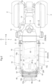
FIG. 2 is a plan view showing the entire tractor. -
FIG. 3 is a side view showing an upper guard section in a closed posture, a front engine bonnet in a closed state, and a ROPS in a stowed posture. -
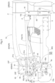
FIG. 4 is a side view of a motive section while the upper guard section is in an open posture and the front engine bonnet open. -
FIG. 5 is a plan view showing a reducing agent tank, a locking mechanism, and a positioning mechanism. -
FIG. 6 is a front view of a front guard. -
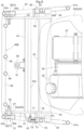
FIG. 7 is a plan view of the front guard. -
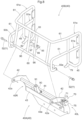
FIG. 8 is a perspective view of a lower guard section and the upper guard section when separated from each other. -
FIG. 9 is a cross-sectional view showing a coupling structure of a left coupling section and a vertically-oriented guard section. -
FIG. 10 is a side view showing a positioning mechanism. -
FIG. 11 is a plan view of the locking mechanism. -
FIG. 12 is a side view of the locking mechanism. -
FIG. 13 is a rear view showing a ROPS receiving section and a ROPS pressing section. -
FIG. 14 is a rear view showing a ROPS receiving section and a ROPS pressing section of another embodiment. - Hereinafter, an example embodiment of the present invention will be described with reference to the drawings.
- Note that, in the following description, in relation to the travel body of a tractor (example of "work vehicle"), the direction of the F arrow in
FIGS. 1 ,2 and10 indicates "body front", the direction of the B arrow inFIGS. 1 ,2 and10 indicates "body back", the direction of the U arrow inFIGS. 1 and10 indicates "body up", the direction of the D arrow inFIGS. 1 and10 indicates "body down", the direction of the L arrow inFIG. 2 indicates "body left", and the direction of the R arrow inFIG. 2 indicates "body right". - As shown in
FIGS. 1 and2 , the tractor includes a travel body 3 supported by a pair of left and rightfront wheels 1 that are steerable and drivable and a pair of left and rightrear wheels 2 that are drivable. The travel body 3 includes abody frame 4 constituted by anengine 5, aflywheel housing 6 provided in a rear section of theengine 5, aclutch housing 7 coupled to a rear section of theflywheel housing 6, atransmission case 8 coupled to a rear section of theclutch housing 7, and afront frame 9 coupled to a lower section of theengine 5. In a front section of the travel body 3 are provided amotive section 10 including theengine 5, aweight support 11, and afront guard 40. In a rear section of the travel body 3 is formed adriving section 12. The drivingsection 12 includes a driver'sseat 13, asteering wheel 14 for steering thefront wheels 1, and aROPS 15. In a rear section of thetransmission case 8 are provided alink mechanism 16 for coupling work machinery such as a rotary tiller (not shown) in such a manner as to be liftable and lowerable, and apower takeoff shaft 17 that takes power from theengine 5 and outputs power to the coupled work machinery. - As shown in
FIGS. 2 and4 , themotive section 10 includes anengine compartment 21 formed by anengine bonnet 20. Theengine 5 is provided in theengine compartment 21. Theengine 5 is a diesel engine whose crankshaft (not shown) extends in the front-rear direction of the body. Upward of a rear section of theengine 5 is provided a first exhaustgas treatment device 22 for purifying exhaust gas emitted by theengine 5. On the rearward side of theengine 5 is provided a second exhaustgas treatment device 23 for purifying exhaust gas emitted by theengine 5. On the forward side of theengine 5 in a front section of theengine compartment 21 are provided aradiator 24 for cooling theengine 5, a reducingagent tank 25, a reducingagent pump 26 and abattery 27. As shown inFIGS. 2 ,4 and5 , the reducingagent tank 25, the reducingagent pump 26 and thebattery 27 are arranged alongside each other in the width direction of the body on the forward side of theradiator 24. The reducingagent tank 25, the reducingagent pump 26 and thebattery 27 are arranged alongside each other in the width direction of the body with the reducingagent pump 26 located between the reducingagent tank 25 and thebattery 27. - The first exhaust
gas treatment device 22 performs exhaust gas purification treatment that involves collecting diesel particulates contained in the exhaust gas emitted from theengine 5 with a collection filter (not shown) and reducing the diesel particulates. The second exhaustgas treatment device 23 performs exhaust gas purification treatment that involves injecting a urea solution serving as a reducing agent into the exhaust gas emitted from the first exhaustgas treatment device 22 to promote hydrolysis, and reducing the nitrogen oxide content of the exhaust gas. - The reducing
agent tank 25 stores the urea solution serving as a reducing agent to be supplied to the second exhaustgas treatment device 23. The reducingagent pump 26 is driven by power from thebattery 27, and functions to extract urea solution from the reducingagent tank 25 and supply the extracted urea solution to the second exhaustgas treatment device 23. - As shown in
FIGS. 1 ,2 and4 , theengine bonnet 20 forms a front portion of theengine compartment 21 and is divided into a front engine bonnet 20Athat covers the reducingagent tank 25, theradiator 24 and the like and arear engine bonnet 20B that is on the rearward side of thefront engine bonnet 20A and covers the second exhaustgas treatment device 23. As shown inFIG. 4 , thefront engine bonnet 20A is supported by therear engine bonnet 20B in such a manner as to be swingably openable and closable in an up-down direction of the body with an opening and closing axis P that extends in the width direction of the body in a rear section of thefront engine bonnet 20A as the swing fulcrum. Therear engine bonnet 20B supports thefront engine bonnet 20A by means of asupport shaft 28 that supports thefront engine bonnet 20A in such a manner as to be swingable up and down being provided in asupport frame 29 coupled to therear engine bonnet 20B. Attached to extend from the inside of thefront engine bonnet 20A to asupport arm 30 that extends forward and upward from theengine 5 is adamper 31 that urges thefront engine bonnet 20A open. Thesupport arm 30 is supported by thesupport frame 29 via acoupling rod 32 coupled to acoupling section 29a of thesupport frame 29 and thesupport arm 30. - As shown in
FIG. 3 , theweight support 11 protrudes forward from afront section 9a of thefront frame 9 of thebody frame 4 and supports acounter weight 33. - The
counter weight 33 is divided into a plurality ofsplit weights 33a in the width direction of the body, and thesplit weights 33a are each supported by theweight support 11 by being latched to theweight support 11. As shown inFIG. 3 , theweight support 11 includes anupper latching section 11a on an upper front section of theweight support 11 and alower latching section 11b provided on the downward side of theupper latching section 11a. Thesplit weights 33a are each supported by theweight support 11 as a result of a hook section formed on an upper rear section of thesplit weight 33a being latched onto theupper latching section 11a, and a coupling hole provided on the downward side of the hook section being latched onto thelower latching section 11b. - As shown in
FIGS. 3 ,6 and the like, thefront guard 40 includes alower guard section 40A fixedly supported by thebody frame 4 and anupper guard section 40B supported by thelower guard section 40A. - In
FIGS. 6 and7 , theweight support 11 has been removed. As shown inFIGS. 3 ,6 and7 , thelower guard section 40A is fixedly supported by thefront frame 9 of thebody frame 4, as a result of a lower section of thelower guard section 40A being coupled to thefront section 9a of thefront frame 9. Thelower guard section 40A is coupled to thefront frame 9 by coupling bolts 41 (seeFIG. 6 ). Thelower guard section 40A extends forward and upward from thefront section 9a of thefront frame 9 while passing above thecounter weight 33 latched onto theweight support 11. - Specifically, as shown in
FIGS. 3 ,6 ,7 and8 , thelower guard section 40A includes a pair of left and right vertically-oriented guard sections (i.e., sections extending in the up-down direction of the body) 42 that are arc-shaped in side view in such a manner as to pass above thecounter weight 33 latched onto theweight support 11, a lower laterally-orientedguard section 43 that bridges between a lower end section of the right vertically-orientedguard section 42 and a lower end section of the left vertically-orientedguard section 42, an upper laterally-orientedguard section 44 that bridges between an intermediate section of the right vertically-orientedguard section 42 in the up-down direction and an intermediate section of the left vertically-orientedguard section 42 in the up-down direction. - The
lower guard section 40A includes anattachment section 43a on a lower section of the lower laterally-orientedguard section 43, and is fixedly supported by thefront frame 9 as a result of theattachment section 43a being coupled to thefront section 9a of thefront frame 9. Theattachment section 43a is coupled to thefront frame 9 by the coupling bolts 41 (seeFIG. 6 ). - As shown in
FIGS. 3 and4 , theupper guard section 40B is coupled to thelower guard section 40A via a coupling axis Y that extends in the width direction of the body in a lower front section of theupper guard section 40B, and is supported by thelower guard section 40A in such a manner as to be changeable between a closed posture (seeFIG. 3 ) in which theupper guard section 40B covers afront portion 20F of the closedfront engine bonnet 20A and an open posture (seeFIG. 4 ) in which theupper guard section 40B is swung on the forward side of the body from the closed posture to open up the front of thefront engine bonnet 20A with the coupling axis Y as the swing fulcrum. - The coupling axis Y of the
front guard 40 is forward of thefront engine bonnet 20A. A large open space can thus be created between the openupper guard section 40B and theengine compartment 21. - In the
front guard 40, the coupling axis Y coincides positionally in the up-down direction of the body with an intermediate point 20C (seeFIG. 4 ), in the up-down direction of the body, of thefront section 20F of the closedfront engine bonnet 20A. This enables the ground height of the coupling axis Y to be raised, and theupper guard section 40B in the open posture to be supported in a forward leaning state (seeFIG. 4 ). - The
lower guard section 40A supports theupper guard section 40B as a result of aleft coupling section 50a (seeFIG. 8 ) on a left lower front section of theupper guard section 40B being coupled to adistal end 42a of the left vertically-orientedguard section 42 of thelower guard section 40A, and aright coupling section 50b (seeFIG. 8 ) on a right lower front section of theupper guard section 40B being coupled to adistal end 42a of the right vertically-orientedguard section 42 of thelower guard section 40A. - As shown in
FIG. 9 , acoupling structure 51 coupling theleft coupling section 50a and the left vertically-orientedguard section 42 is constituted by afulcrum shaft 52 that includes the coupling axis Y and a pressingmember 53. Thefulcrum shaft 52 is inserted through theleft coupling section 50a and thedistal end 42a of the vertically-orientedguard section 42 and couples theleft coupling section 50a to the vertically-orientedguard section 42 in a swingable manner, and the pressingmember 53 is fitted onto thefulcrum shaft 52 on the opposite side to theleft coupling section 50a with respect to thedistal end 42a. Afriction plate 54 is interposed both between theleft coupling section 50a and thedistal end section 42a and between thedistal end 42a and the pressingmember 53. - On a bent end section of the pressing
member 53 is arotation stopper 53a that covers theleft coupling section 50a from above. Bringing therotation stopper 53a into contact with theleft coupling section 50a to stop rotation of the pressingmember 53 relative to theleft coupling section 50a allows the pressingmember 53 to swing together with theleft coupling section 50a relative to the vertically-orientedguard section 42 with the coupling axis Y as the swing fulcrum. Therotation stopper 53a being slidable along the coupling axis Y relative to theleft coupling section 50a allows the pressingmember 53 to move along the coupling axis Y relative to the vertically-orientedguard section 42. - On the opposite side to the
friction plate 54 relative to the pressingmember 53, two plate springs 55, an annularpressing plate 56 and acap 57 that covers the plate springs 55 and thepressing plate 56 are fitted onto thefulcrum shaft 52. By tightening threadedhole members 58 that engage a threaded shaft section of thefulcrum shaft 52, thepressing plate 56 is pushed toward the plate springs 55 by the threadedhole members 58, and the two plate springs 55 are elastically deformed as a result of being pressed by thepressing plate 56 against the pressingmember 53 together with thecap 57. The pressingmember 53 is pressed toward theleft coupling section 50a by the elastic restoring force of the plate springs 55, resulting in one of thefriction plates 54 being sandwiched between theleft coupling section 50a and thedistal end section 42a and theother friction plate 54 being sandwiched between the pressingmember 53 and thedistal end section 42a, and thefriction plates 54 thereby applying frictional resistance to swinging of theleft coupling section 50a relative to the vertically-orientedguard section 42. Thefriction plates 54 apply frictional resistance to swinging of theupper guard section 40B, when changing the posture of theupper guard section 40B. Theright coupling section 50b is coupled to thefront end 42a of the right vertically-orientedguard section 42 by thefulcrum shaft 52.Friction plates 54 are not interposed in the coupling structure of theright coupling section 50b and the right vertically-orientedguard section 42. - As shown in
FIGS. 6 ,7 and8 , theupper guard section 40B includes a laterally-oriented section (i.e., section extending in the left-right direction (width direction) of the body) 60 extending in the width direction of the body at two (upper and lower) places in the front section of theupper guard section 40B, a pair of left and right upper longitudinally-oriented sections (i.e., sections extending in the front-rear direction of the body) 61 respectively coupled at the front end to the left and right ends of the upper laterally-orientedsection 60, and a pair of left and right lower longitudinally-orientedsections 61 respectively coupled at the front end to the left and right ends of the lower laterally-orientedsection 60. - As shown in
FIGS. 3 ,6 and7 , the two (upper and lower) laterally-orientedsections 60 are forward of thefront engine bonnet 20A and upward of thecounter weight 33 latched onto theweight support 11. While theupper guard section 40B is in the closed posture, the pair of left and right upper longitudinally-orientedsections 61 respectively extend rearward in the front-rear direction of the body from the left end and right end of the upper laterally-orientedsection 60, andrear sections 61a of the upper longitudinally-orientedsections 61 are lateral of thefront portion 20F of the closedfront engine bonnet 20A. While theupper guard section 40B is in the closed posture, the pair of left and right lower longitudinally-orientedsections 61 respectively extend rearward in the front-rear direction of the body from the left end and right end of the lower laterally-orientedsection 60, andrear sections 61a of the lower longitudinally-orientedsections 61 are lateral of thefront portion 20F of the closedfront engine bonnet 20A. - As shown in
FIGS. 2 and7 , while theupper guard section 40B is in the closed posture, the pair of left and right upper longitudinally-orientedsections 61 and the pair of left and right lower longitudinally-orientedsections 61 are outwardly oriented laterally to the rear in such a manner that an interval K between a center C in a left-right direction of the body in plan view of the body and each longitudinally-orientedsection 61 widens as the longitudinally-orientedsection 61 extend rearward. - In the present embodiment, two laterally-oriented
sections 60 are provided, and two pairs of left and right longitudinally-orientedsections 61 are provided, but only one laterally-orientedsection 60 or three or more laterally-orientedsections 60 may be provided, and only one pair of longitudinally-orientedsections 61 or three or more pairs of longitudinally-orientedsections 61 may be provided. - As shown in
FIG. 8 , theupper guard section 40B combines a bent round steel pipe constituting the upper laterally-orientedsection 60, the left and right upper longitudinally-orientedsections 61 and the like, a straight round steel pipe constituting the lower laterally-orientedsection 60, bent round steel pipes constituting the left and right lower longitudinally-orientedsections 61, round steel pipes coupling the upper bent round steel pipe to the straight round steel pipe, and round steel pipes coupling the upper bent round steel pipe to the lower bent round steel pipes. In the present embodiment, theupper guard section 40B is made of round steel pipes, but various members other than round steel pipes, such as round steel members, square steel rods, square steel pipes and steel strips, can be employed for theupper guard section 40B. - As shown in
FIGS. 5 and7 , thelower guard section 40A includesside sections side section 40L being provided with alocking mechanism 70 capable of fixing theupper guard section 40B in the closed posture, and theside section 40R being provided with apositioning mechanism 80 capable of positioning theupper guard section 40B in the closed posture. - In the present embodiment, as shown in
FIGS. 5 and7 , thelocking mechanism 70 is provided on theleft side section 40L of thelower guard section 40A. Thelocking mechanism 70 may also be provided on theright side section 40R of thelower guard section 40A instead of theleft side section 40L. As shown inFIGS. 5 ,11 and 12 , thelocking mechanism 70 includes a lockingshaft 71 for fixing theupper guard section 40B in the closed posture, anoperation tool 72 for releasing fixing of theupper guard section 40B in the closed posture, and a lock-urgingspring 73. - As shown in
FIGS. 11 and 12 , the lockingshaft 71 is supported by asupport hole 74 provided in the front-rear direction in the left vertically-orientedguard section 42 and asupport hole 76 provided in the front-rear direction in afirst support 75a on the lateral outer side of the body relative to the vertically-orientedguard section 42. Thefirst support 75a is provided on asupport 75 that protrudes laterally outward of the body from the vertically-orientedguard section 42, and is supported by the vertically-orientedguard section 42. The lockingshaft 71 is supported in such a manner as to be slidable between a locked position in the rear section of the support holes 74 and 76 and an unlocked position in the front section of the support holes 74 and 76. Theoperation tool 72 extends forward from the lockingshaft 71, and is supported in such a manner as to be slidable back and forth by a cutaway section provided in asecond support 75b of thesupport 75 and a through hole provided in asupport 77 of thesupport 75. Thespring 73 is fitted onto theoperation tool 72 and disposed between twospring retainers 78 provided on theoperation tool 72 between the lockingshaft 71 and thesecond support 75b, and urges the lockingshaft 71 to slide to the locked position. - As shown in
FIG. 8 , a lockingarm 79 is provided on a left rear section of theupper guard section 40B. Specifically, the lockingarm 79 extends from a bentround steel pipe 45 constituting the left upper longitudinally-orientedsection 61 of theupper guard section 40B. - The
lock mechanism 70 is locked as a result of the lockingshaft 71 being pushed from above by acam section 79a formed on a lower section of the distal end side of the lockingarm 79 and sliding toward the unlocked position from locked position against thespring 73 when theupper guard section 40B is swung toward the closed posture, allowing the lockingarm 79 to move downward below the lockingshaft 71, and the lockingshaft 71 then being returned to the locked position by thespring 73 and engaging an upper section of the distal end side of the lockingarm 79 when theupper guard section 40B achieves the closed posture, as shown inFIG. 12 , thereby fixing theupper guard section 40B in the closed posture. - The
lock mechanism 70 is unlocked as a result of the lockingshaft 71 being operated by theoperation tool 72 to slide from the locked position to the unlocked position and disengage forward from the lockingarm 79 when theoperation tool 72 is operated to slide forward against thespring 73, thereby releasing fixing of theupper guard section 40B in the closed posture. - In the present embodiment, as shown in
FIGS. 5 and7 , thepositioning mechanism 80 is provided on theright side section 40R of thelower guard section 40A. Thepositioning mechanism 80 may also be provided on theleft side section 40L of thelower guard section 40A instead of theright side section 40R. As shown inFIGS. 8 and10 , thepositioning mechanism 80 includes apositioning section 81 provided on the right vertically-orientedguard section 42. - As shown in
FIGS. 8 and10 , acontact section 82 that is contactable with thepositioning section 81 is provided on a right rear section of theupper guard section 40B. Specifically, thecontact section 82 extends from a bentround steel pipe 46 constituting the right upper longitudinally-orientedsection 61 of theupper guard section 40B. - The
positioning mechanism 80 positions theupper guard section 40B in the closed posture, as shown inFIG. 10 , as a result of thecontact section 82 of theupper guard section 40B coming into contact with thepositioning section 81 from above when theupper guard section 40B is swung to the closed posture, and thepositioning section 81 receiving and supporting thecontact section 82 from below. - The
positioning mechanism 80 releases positioning of theupper guard section 40B in the closed posture as a result of thecontact section 82 separating upward from thepositioning section 81 when theupper guard section 40B is swung toward the open posture from the closed posture. - As shown in
FIGS. 1 and2 , theROPS 15 includes a pair of left andright posts 15a and atop section 15b that extends from an upper section of one of theposts 15a toward an upper section of theother post 15a and is coupled to the upper section of theleft post 15a. Thetop section 15b is laterally-oriented in the width direction of the body. - As a result of lower sections of the left and
right posts 15a being respectively coupled to a pair of left andright supports 85 of thebody frame 4 via a coupling axis Z that extends in the width direction of the body, theROPS 15 is supported by thebody frame 4 in such a manner as to be uprightly swingable with the coupling axis Z as the swing fulcrum. TheROPS 15 is changeable between a use posture in which theROPS 15 stands upright in a front section of the drivingsection 12 as shown inFIG. 1 , and a stowed posture in which theROPS 15 lies down in such a manner that the pair of left andright posts 15a are lateral of thefront engine bonnet 20A and thetop section 15b is on the rearward side of the coupling axis Y of theupper guard section 40B and on the forward side of thefront engine bonnet 20A as shown inFIGS. 2 and3 . TheROPS 15 is fixed in the use posture by attaching a locking pin to a pin hole 18 (seeFIG. 3 ) provided in thesupport 85 and apin hole 15c provided in thesupport 15a. - As shown in
FIGS. 2 and3 , when theROPS 15 is stowed and theupper guard section 40B is closed, thetop section 15b is lower than both the upper and lower longitudinally-orientedsections 61. By closing theupper guard section 40B after stowing theROPS 15, the posture of theupper guard section 40B can be changed from open to closed without the longitudinally-orientedsections 61 hitting thetop section 15b. The posture of theupper guard section 40B can be changed from closed to open with theROPS 15 in the stowed posture. - As shown in
FIG. 3 , when theROPS 15 is stowed and theupper guard section 40B is closed, thetop section 15b sits on aROPS receiving section 90 provided on thelower guard section 40A and is pressed against theROPS receiving section 90 by aROPS pressing section 95 provided on theupper guard section 40B, thereby sandwiching thetop section 15b from above and below by theROPS receiving section 90 and theROPS pressing section 95. - As shown in
FIGS. 6 ,8 and13 , theROPS receiving section 90 protrudes upward from the upper laterally-orientedguard section 44 of thelower guard section 40A. TheROPS receiving section 90 includes acushioning section 91 protruding upward from the upper 90a of theROPS receiving section 90, and receives thetop section 15b with thecushioning section 91. - As shown in
FIGS. 6 ,8 and13 , theROPS pressing section 95 is supported by the upper and lower laterally-orientedsections 60 of theupper guard section 40B. Specifically, the upper laterally-orientedsection 60 is coupled to the lower laterally-orientedsection 60 by a pair of vertically-orientedround steel pipes 96 to which asupport 97 is coupled, and theROPS pressing section 95 is coupled to thesupport 97 by couplingbolts 98. The ROPSpressing section 95 includes acushioning section 99 protruding downward from apressing side 95a of theROPS pressing section 95, and presses thetop section 15b toward theROPS receiving section 90 with thecushioning section 99. In the present embodiment, thecushioning sections ROPS receiving section 90 and theROPS pressing section 95 are made of rubber. Leather, springs or the like can be employed as thecushioning sections - Rattling of the
upper guard section 40B in the closed posture when theROPS 15 is not stowed can be prevented by theROPS pressing section 95. This similarly applies to work vehicles not equipped with theROPS 15. Specifically, theROPS pressing section 95 is changed from the laterally-oriented posture for pressing thetop section 15b in which thepressing side 95a faces downward to a vertically-oriented posture (posture indicated by two-dot chain line A inFIG. 13 ) in which thepressing side 95a faces laterally and is coupled to thesupport 97. Alateral side 95b of theROPS pressing section 95 thus protrudes downward from thesupport 97 and is pressed against thecushioning section 91 of theROPS receiving section 90, thereby enabling rattling of the closedupper guard section 40B to be prevented. - When working in an orchard, for example, the
ROPS 15 is stowed and theupper guard section 40B is closed, as shown inFIGS. 2 and3 . In the case where, however, theROPS 15 is changed from the use posture to the stowed posture when theupper guard section 40B is closed, theROPS 15 is stowed after opening theupper guard section 40B so that thetop section 15b does not hit the longitudinally-orientedsections 61, and theupper guard section 40B is then returned to the closed posture. Theupper guard section 40B is thus positioned in the closed posture by thepositioning mechanism 80. Also, theupper guard section 40B is securely fixed in the closed posture by thelocking mechanism 70. Branches or the like can be blocked by the upper and lower longitudinally-orientedsections 61 in such a manner as to not get between thefront guard 40 and thefront engine bonnet 20A, while protecting thefront engine bonnet 20A with thefront guard 40 from being hit by branches or the like. Furthermore, the tractor can travel while pushing branches toward the lateral outer side of the body with the upper and lower longitudinally-orientedsections 61 that are outwardly oriented laterally to the rear. Also, since thetop section 15b of theROPS 15 is sandwiched by theROPS receiving section 90 and theROPS pressing section 95, theROPS 15 can be held in the stowed posture. TheROPS 15 can thereby be prevented from hitting branches or the like. Also, rattling of theROPS 15 during travel can be suppressed. - When carrying out work on the
engine compartment 21, such as refilling the reducingagent tank 25 with urea solution, both theupper guard section 40B and thefront engine bonnet 20A are opened, as shown inFIG. 4 . Theupper guard section 40B can be opened with theupper guard section 40B stowed, without the upper and lower longitudinally-orientedsections 61 hitting thetop section 15b of the stowedROPS 15 when opening theupper guard section 40B. Theengine compartment 21 can be opened up wide, and a large work space can be created between the openupper guard section 40B and theengine compartment 21, facilitating work carried out on theengine compartment 21. The structure of the present invention facilitates refilling of the reducingagent tank 25. - When the posture of the
upper guard section 40B is changed from open to closed, thefriction plates 54 apply frictional resistance to theupper guard section 40B. Theupper guard section 40B can thereby be prevented from swinging vigorously due to the weight of theupper guard section 40B. - When refilling the reducing
agent tank 25 with urea solution, a refill tank (not shown) can be easily supported by latching a lower section of the refill tank onto alatching section 44a (seeFIG. 7 ) provided on the upper laterally-orientedguard section 44 of thelower guard section 40A, thereby facilitating refilling. -
- (1)
FIG. 14 is a front view showing theROPS receiving section 90 andROPS pressing section 95 of another embodiment. TheROPS receiving section 90 of this other embodiment is supported by the upper laterally-orientedguard section 44 via asupport 92 that stands up from the upper laterally-orientedguard section 44 of thelower guard section 40A, a pair ofcoupling bolts 93 that couple anupper section 92a of thesupport 92 to theROPS receiving section 90, and the like. - Attachment of the
ROPS receiving section 90 to the pair ofcoupling bolts 93 is achieved by thecoupling bolts 93 protruding upward from thesupport 92 and being inserted through anupper section 90a of theROPS receiving section 90, and respective pairs oftreaded hole members 94 that sandwich theupper section 90a from above and below engaging thecoupling bolts 93. In each of the pair ofcoupling bolts 93, the attachment position of theROPS receiving section 90 on thecoupling bolt 93 is changed up and down, by rotating the pair of threadedhole members 94 to change the attachment position of the pair of threadedhole members 94 on thecoupling bolt 93, thereby enabling the attachment height of theROPS receiving section 90 relative to thelower guard section 40A to be adjusted. - As shown in
FIG. 14 , theROPS pressing section 95 of this other embodiment is supported by the upper and lower laterally-orientedsections 60 as a result of a support structure having a similar configuration to the support structure of theROPS pusher 95 shown inFIG. 13 . - Rattling of the
upper guard section 40B in the closed posture when theROPS 15 is not stowed can be prevented by theROPS pressing section 95. This similarly applies to work vehicles not equipped with theROPS 15. Specifically, theROPS pressing section 95 is changed from the laterally-oriented posture for pressing thetop section 15b to a vertically-oriented posture and is coupled to thesupport 97. Thelateral side 95b of theROPS pressing section 95 thus protrudes downward from thesupport 97 and is pressed against thecushioning section 91 of theROPS receiving section 90, thereby preventing rattling of the closedupper guard section 40B. - (2) In the above embodiment, an example is illustrated in which the reducing
agent tank 25 is provided in a front section of theengine compartment 21, but the present invention is not limited thereto, and a fuel tank (not shown) for the engine or both the fuel tank and the reducingagent tank 25 may be provided in a front section of theengine compartment 21. The structure of the present invention facilitates refilling of the fuel tank. - (3) In the above embodiment, the
locking mechanism 70 is provided on theleft side section 40L of thelower guard section 40A and thepositioning mechanism 80 is provided on theright side section 40R of thelower guard section 40A, but thelocking mechanism 70 may be provided on theright side section 40R of thelower guard section 40A and thepositioning mechanism 80 may be provided on theleft side section 40L of thelower guard section 40A. - (4) In the above embodiment, an example is illustrated in which the
front engine bonnet 20A and therear engine bonnet 20B are provided, but only one engine bonnet openable and closable up and down may be provided. - (5) In the above embodiment, an example is illustrated in which the coupling axis Y coincides positionally in the up-down direction of the body with the intermediate point 20C, in the up-down direction of the body, of the
front section 20F of thefront engine bonnet 20A, but the invention is not limited thereto, and the coupling axis Y may be downward or upward of the intermediate point 20C. - (6) In the above embodiment, an example is illustrated in which two (upper and lower) pairs of longitudinally-oriented
sections 61 are provided, but only one pair of longitudinally-orientedsections 61 or three or more pairs of longitudinally-orientedsections 61 may be provided. - (7) In the above embodiment, an example is illustrated in which the
weight support 11 is provided, but theweight support 11 need not be provided. - (8) In the above embodiment, an example is illustrated in which the
ROPS 15 is provided, but theROPS 15 need not be provided. - (9) In the above embodiment, an example is illustrated in which the
ROPS receiving section 90 and theROPS pressing section 95 are provided, but theROPS receiving section 90 and theROPS pressing section 95 need not be provided, or only theROPS receiving section 90 may be provided. - (10) In the above embodiment, an example is illustrated in which the
latching section 44a is provided, but thelatching section 44a need not be provided. - (11) The present invention can, for example, be applied to various work vehicles provided with an engine bonnet and a front guard.
-
- 4
- Body frame
- 5
- Engine
- 9
- Front frame (body frame)
- 11
- Weight support
- 12
- Driving section
- 15
- ROPS
- 15a
- Post
- 15b
- Top section
- 20A
- Front engine bonnet (engine bonnet)
- 20F
- Front portion
- 20C
- Intermediate point
- 21
- Engine compartment
- 23
- Second exhaust gas treatment device
- 25
- Reducing agent tank
- 33
- Counter weight
- 40
- Front guard
- 40A
- Lower guard section
- 40B
- Upper guard section
- 40L
- Left side section (first side section)
- 40R
- Right side section (second side section)
- 44a
- Latching section
- 60
- Laterally-oriented section
- 61
- Longitudinally-oriented section
- 61a
- Rear section
- 70
- Locking mechanism
- 80
- Positioning mechanism
- 81
- Positioning section
- 82
- Contact section
- 90
- ROPS receiving section
- 95
- ROPS pressing section
- C
- Center
- K
- Interval
- P
- Opening and closing shaft
Claims (13)
- A work vehicle comprising:an engine bonnet in a front section of a body of the work vehicle and forming an engine compartment, the engine bonnet being swingably openable and closable in an up-down direction of the body with an opening and closing axis extending in a width direction of the body in a rear section of the engine bonnet as a swing fulcrum; anda front guard covering a front portion of the engine bonnet and including a lower guard section fixedly supported by a body frame and an upper guard section supported by the lower guard section, wherein:the upper guard section is coupled to the lower guard section via a coupling axis lying in the width direction of the body, and is supported in such a manner as to be changeable between a (i) closed posture, in which the upper guard section covers the front portion, and (ii) an open posture, in which the upper guard section is swung on a forward side of the body with the coupling shaft as the swing fulcrum,the coupling axis is forward of the engine bonnet, andthe upper guard section includes:a laterally-oriented section forward of the engine bonnet and extending in the width direction of the body; andlongitudinally-oriented sections extending rearward in a front-rear direction of the body respectively from left and right ends of the laterally-oriented section while the upper guard section is in the closed posture.
- The work vehicle according to claim 1, wherein:
the coupling axis coincides positionally in the up-down direction of the body with an intermediate point, in the up-down direction of the body, of the front portion of the engine bonnet in a closed state. - The work vehicle according to claim 1 or 2, wherein:
the longitudinally-oriented sections each include a rear section that is lateral of the engine bonnet in a closed state. - The work vehicle according to claim 3, wherein:
each of the longitudinally-oriented sections is separated from a center of the body in a left-right direction of the body in plan view of the body by an interval that widens as the longitudinally-oriented section extends rearward while the upper guard section is in the closed posture. - The work vehicle according to any one of claims 1 to 4, further comprising:
a weight support protruding forward from the body frame and to which a counter weight is latched, wherein:
the lower guard section extends diagonally forward and upward from the body frame in such a manner as to pass above the counter weight latched to the weight support. - The work vehicle according to any one of claims 1 to 5, further comprising:a lock mechanism provided on a first side section out of two side sections of the lower guard section, and switchable between (i) a locked state, in which the upper guard section is fixed in the closed posture, and (ii) an unlocked state, in which fixing of the upper guard section in the closed posture is released; anda positioning mechanism provided on a second side section out of the two side sections of the lower guard section, and including (i) a positioning section provided on the lower guard section and (ii) a contact section provided on the upper guard section and configured to come into contact with and separate from the positioning section, the positioning mechanism being configured to position the lower guard section in the closed posture with the positioning section and the contact section.
- The work vehicle according to any one of claims 1 to 6, further comprising:
a fuel tank in a front section of the engine compartment. - The work vehicle according to any one of claims 1 to 7, further comprising:an engine;an exhaust gas treatment device configured to purify exhaust gas emitted from the engine; anda reducing agent tank in a front section of the engine compartment and configured to store a reducing agent to be supplied to the exhaust gas treatment device.
- The work vehicle according to claim 8, further comprising:
a latching section on the lower guard section and configured to latch onto a refill tank configured to refill the reducing agent tank with the reducing agent. - The work vehicle according to any one of claims 1 to 9, further comprising:a driving section in a rear section of the body; anda ROPS provided in the driving section and including a post and a top section extending laterally from an upper section of the post, the ROPS being coupled to the body frame in such a manner as to be uprightly swingable, and being supported in such a manner as to be changeable between a (i) use posture, in which the ROPS stands upright, and (ii) a stowed posture, in which the ROPS lies down in such a manner that the post is located laterally of the engine bonnet and the top section is located behind the coupling shaft and in front of the engine bonnet.
- The work vehicle according to claim 10, wherein:
while the ROPS is in the stowed posture, the top section is lower than the longitudinally-oriented sections. - The work vehicle according to claim 10 or 11, further comprising:
a ROPS receiving section on the lower guard section, and on which the top section placeable while the ROPS is in the stowed posture. - The work vehicle according to claim 12, further comprising:
a ROPS pressing section on the upper guard section and configured to press the top section against the ROPS receiving section while the upper guard section is in the closed posture.
Applications Claiming Priority (1)
| Application Number | Priority Date | Filing Date | Title |
|---|---|---|---|
| JP2022101356A JP7770262B2 (en) | 2022-06-23 | 2022-06-23 | Work vehicle |
Publications (1)
| Publication Number | Publication Date |
|---|---|
| EP4296144A1 true EP4296144A1 (en) | 2023-12-27 |
Family
ID=86497940
Family Applications (1)
| Application Number | Title | Priority Date | Filing Date |
|---|---|---|---|
| EP23174543.1A Pending EP4296144A1 (en) | 2022-06-23 | 2023-05-22 | Work vehicle |
Country Status (3)
| Country | Link |
|---|---|
| US (1) | US12534034B2 (en) |
| EP (1) | EP4296144A1 (en) |
| JP (1) | JP7770262B2 (en) |
Cited By (1)
| Publication number | Priority date | Publication date | Assignee | Title |
|---|---|---|---|---|
| US20230415688A1 (en) * | 2022-06-23 | 2023-12-28 | Kubota Corporation | Work vehicle |
Families Citing this family (1)
| Publication number | Priority date | Publication date | Assignee | Title |
|---|---|---|---|---|
| US12391316B2 (en) * | 2022-11-30 | 2025-08-19 | Cnh Industrial America Llc | Hood assembly for a work vehicle |
Citations (5)
| Publication number | Priority date | Publication date | Assignee | Title |
|---|---|---|---|---|
| US20080292435A1 (en) * | 2007-05-22 | 2008-11-27 | Turner Gary D | Atv loading device |
| JP2013018324A (en) * | 2011-07-08 | 2013-01-31 | Kubota Corp | Front guard of working vehicle |
| JP2017087904A (en) * | 2015-11-06 | 2017-05-25 | 株式会社クボタ | Work vehicle |
| JP2019108004A (en) * | 2017-12-18 | 2019-07-04 | 株式会社クボタ | Tractor |
| JP2021014191A (en) | 2019-07-12 | 2021-02-12 | 株式会社クボタ | Work vehicle front guard |
Family Cites Families (8)
| Publication number | Priority date | Publication date | Assignee | Title |
|---|---|---|---|---|
| JPS544223Y2 (en) * | 1974-07-24 | 1979-02-24 | ||
| JPS53158030U (en) * | 1977-05-17 | 1978-12-11 | ||
| JPH061491Y2 (en) * | 1988-02-09 | 1994-01-12 | 株式会社クボタ | Vehicle front protector device |
| JP2014189184A (en) | 2013-03-27 | 2014-10-06 | Iseki & Co Ltd | Tractor |
| US9914487B2 (en) * | 2015-11-06 | 2018-03-13 | Kubota Corporation | Work vehicle |
| JP6877259B2 (en) | 2017-06-21 | 2021-05-26 | 株式会社クボタ | Harvester |
| JP7500398B2 (en) | 2020-11-17 | 2024-06-17 | ヤンマーホールディングス株式会社 | Tractor |
| JP7770262B2 (en) * | 2022-06-23 | 2025-11-14 | 株式会社クボタ | Work vehicle |
-
2022
- 2022-06-23 JP JP2022101356A patent/JP7770262B2/en active Active
-
2023
- 2023-05-18 US US18/198,893 patent/US12534034B2/en active Active
- 2023-05-22 EP EP23174543.1A patent/EP4296144A1/en active Pending
Patent Citations (5)
| Publication number | Priority date | Publication date | Assignee | Title |
|---|---|---|---|---|
| US20080292435A1 (en) * | 2007-05-22 | 2008-11-27 | Turner Gary D | Atv loading device |
| JP2013018324A (en) * | 2011-07-08 | 2013-01-31 | Kubota Corp | Front guard of working vehicle |
| JP2017087904A (en) * | 2015-11-06 | 2017-05-25 | 株式会社クボタ | Work vehicle |
| JP2019108004A (en) * | 2017-12-18 | 2019-07-04 | 株式会社クボタ | Tractor |
| JP2021014191A (en) | 2019-07-12 | 2021-02-12 | 株式会社クボタ | Work vehicle front guard |
Cited By (2)
| Publication number | Priority date | Publication date | Assignee | Title |
|---|---|---|---|---|
| US20230415688A1 (en) * | 2022-06-23 | 2023-12-28 | Kubota Corporation | Work vehicle |
| US12534034B2 (en) * | 2022-06-23 | 2026-01-27 | Kubota Corporation | Work vehicle |
Also Published As
| Publication number | Publication date |
|---|---|
| JP7770262B2 (en) | 2025-11-14 |
| US12534034B2 (en) | 2026-01-27 |
| JP2024002265A (en) | 2024-01-11 |
| US20230415688A1 (en) | 2023-12-28 |
Similar Documents
| Publication | Publication Date | Title |
|---|---|---|
| US12534034B2 (en) | Work vehicle | |
| US2699223A (en) | Cab over engine vehicle | |
| US7845711B2 (en) | Quick-attach/detach cab for vehicle | |
| GB2063195A (en) | Motor vehicle having windshield unit | |
| DE102014210022A1 (en) | fuel cell vehicle | |
| CN102892612B (en) | Work vehicle | |
| JP2017196987A (en) | Work vehicle | |
| JP2013018324A (en) | Front guard of working vehicle | |
| JP3289327B2 (en) | Tractor safety frame | |
| EP4385861A1 (en) | Off-road vehicle with a dual-hinge hood assembly | |
| US10099640B1 (en) | Pivoting bumper for vehicle | |
| CN109424279B (en) | Latch mechanism for vehicle | |
| JPH11227658A (en) | Fuel lid device for scooter type vehicle | |
| JP2779874B2 (en) | Front grill guard | |
| JP4161593B2 (en) | Passenger management machine | |
| JP2013247904A (en) | Pto shaft cover of agricultural tractor | |
| JPH08113043A (en) | Agricultural tractor | |
| EP3623232B1 (en) | Vehicle security apparatus | |
| JPH0798495B2 (en) | Work vehicle bonnet structure | |
| US20260109211A1 (en) | Modular canopy | |
| EP4368430A1 (en) | Work vehicle | |
| EP4368431A1 (en) | Work vehicle | |
| JPH11127638A (en) | Rice transplanter folding device | |
| JPH0285041A (en) | Work vehicle battery stand mounting structure | |
| JP3492471B2 (en) | Canopy mounting structure for work vehicles |
Legal Events
| Date | Code | Title | Description |
|---|---|---|---|
| PUAI | Public reference made under article 153(3) epc to a published international application that has entered the european phase |
Free format text: ORIGINAL CODE: 0009012 |
|
| STAA | Information on the status of an ep patent application or granted ep patent |
Free format text: STATUS: REQUEST FOR EXAMINATION WAS MADE |
|
| 17P | Request for examination filed |
Effective date: 20230525 |
|
| AK | Designated contracting states |
Kind code of ref document: A1 Designated state(s): AL AT BE BG CH CY CZ DE DK EE ES FI FR GB GR HR HU IE IS IT LI LT LU LV MC ME MK MT NL NO PL PT RO RS SE SI SK SM TR |
|
| RBV | Designated contracting states (corrected) |
Designated state(s): AL AT BE BG CH CY CZ DE DK EE ES FI FR GB GR HR HU IE IS IT LI LT LU LV MC ME MK MT NL NO PL PT RO RS SE SI SK SM TR |