EP4296100A1 - Control system for hybrid vehicle - Google Patents
Control system for hybrid vehicle Download PDFInfo
- Publication number
- EP4296100A1 EP4296100A1 EP23164255.4A EP23164255A EP4296100A1 EP 4296100 A1 EP4296100 A1 EP 4296100A1 EP 23164255 A EP23164255 A EP 23164255A EP 4296100 A1 EP4296100 A1 EP 4296100A1
- Authority
- EP
- European Patent Office
- Prior art keywords
- engine
- motor
- clutch
- control
- hybrid vehicle
- Prior art date
- Legal status (The legal status is an assumption and is not a legal conclusion. Google has not performed a legal analysis and makes no representation as to the accuracy of the status listed.)
- Pending
Links
Images


Classifications
-
- B—PERFORMING OPERATIONS; TRANSPORTING
- B60—VEHICLES IN GENERAL
- B60W—CONJOINT CONTROL OF VEHICLE SUB-UNITS OF DIFFERENT TYPE OR DIFFERENT FUNCTION; CONTROL SYSTEMS SPECIALLY ADAPTED FOR HYBRID VEHICLES; ROAD VEHICLE DRIVE CONTROL SYSTEMS FOR PURPOSES NOT RELATED TO THE CONTROL OF A PARTICULAR SUB-UNIT
- B60W20/00—Control systems specially adapted for hybrid vehicles
- B60W20/10—Controlling the power contribution of each of the prime movers to meet required power demand
- B60W20/15—Control strategies specially adapted for achieving a particular effect
-
- B—PERFORMING OPERATIONS; TRANSPORTING
- B60—VEHICLES IN GENERAL
- B60K—ARRANGEMENT OR MOUNTING OF PROPULSION UNITS OR OF TRANSMISSIONS IN VEHICLES; ARRANGEMENT OR MOUNTING OF PLURAL DIVERSE PRIME-MOVERS IN VEHICLES; AUXILIARY DRIVES FOR VEHICLES; INSTRUMENTATION OR DASHBOARDS FOR VEHICLES; ARRANGEMENTS IN CONNECTION WITH COOLING, AIR INTAKE, GAS EXHAUST OR FUEL SUPPLY OF PROPULSION UNITS IN VEHICLES
- B60K6/00—Arrangement or mounting of plural diverse prime-movers for mutual or common propulsion, e.g. hybrid propulsion systems comprising electric motors and internal combustion engines
- B60K6/20—Arrangement or mounting of plural diverse prime-movers for mutual or common propulsion, e.g. hybrid propulsion systems comprising electric motors and internal combustion engines the prime-movers consisting of electric motors and internal combustion engines, e.g. HEVs
- B60K6/22—Arrangement or mounting of plural diverse prime-movers for mutual or common propulsion, e.g. hybrid propulsion systems comprising electric motors and internal combustion engines the prime-movers consisting of electric motors and internal combustion engines, e.g. HEVs characterised by apparatus, components or means specially adapted for HEVs
- B60K6/38—Arrangement or mounting of plural diverse prime-movers for mutual or common propulsion, e.g. hybrid propulsion systems comprising electric motors and internal combustion engines the prime-movers consisting of electric motors and internal combustion engines, e.g. HEVs characterised by apparatus, components or means specially adapted for HEVs characterised by the driveline clutches
- B60K6/387—Actuated clutches, i.e. clutches engaged or disengaged by electric, hydraulic or mechanical actuating means
-
- B—PERFORMING OPERATIONS; TRANSPORTING
- B60—VEHICLES IN GENERAL
- B60K—ARRANGEMENT OR MOUNTING OF PROPULSION UNITS OR OF TRANSMISSIONS IN VEHICLES; ARRANGEMENT OR MOUNTING OF PLURAL DIVERSE PRIME-MOVERS IN VEHICLES; AUXILIARY DRIVES FOR VEHICLES; INSTRUMENTATION OR DASHBOARDS FOR VEHICLES; ARRANGEMENTS IN CONNECTION WITH COOLING, AIR INTAKE, GAS EXHAUST OR FUEL SUPPLY OF PROPULSION UNITS IN VEHICLES
- B60K6/00—Arrangement or mounting of plural diverse prime-movers for mutual or common propulsion, e.g. hybrid propulsion systems comprising electric motors and internal combustion engines
- B60K6/20—Arrangement or mounting of plural diverse prime-movers for mutual or common propulsion, e.g. hybrid propulsion systems comprising electric motors and internal combustion engines the prime-movers consisting of electric motors and internal combustion engines, e.g. HEVs
- B60K6/50—Architecture of the driveline characterised by arrangement or kind of transmission units
- B60K6/54—Transmission for changing ratio
- B60K6/547—Transmission for changing ratio the transmission being a stepped gearing
-
- B—PERFORMING OPERATIONS; TRANSPORTING
- B60—VEHICLES IN GENERAL
- B60W—CONJOINT CONTROL OF VEHICLE SUB-UNITS OF DIFFERENT TYPE OR DIFFERENT FUNCTION; CONTROL SYSTEMS SPECIALLY ADAPTED FOR HYBRID VEHICLES; ROAD VEHICLE DRIVE CONTROL SYSTEMS FOR PURPOSES NOT RELATED TO THE CONTROL OF A PARTICULAR SUB-UNIT
- B60W10/00—Conjoint control of vehicle sub-units of different type or different function
- B60W10/02—Conjoint control of vehicle sub-units of different type or different function including control of driveline clutches
- B60W10/023—Fluid clutches
-
- B—PERFORMING OPERATIONS; TRANSPORTING
- B60—VEHICLES IN GENERAL
- B60W—CONJOINT CONTROL OF VEHICLE SUB-UNITS OF DIFFERENT TYPE OR DIFFERENT FUNCTION; CONTROL SYSTEMS SPECIALLY ADAPTED FOR HYBRID VEHICLES; ROAD VEHICLE DRIVE CONTROL SYSTEMS FOR PURPOSES NOT RELATED TO THE CONTROL OF A PARTICULAR SUB-UNIT
- B60W10/00—Conjoint control of vehicle sub-units of different type or different function
- B60W10/04—Conjoint control of vehicle sub-units of different type or different function including control of propulsion units
- B60W10/06—Conjoint control of vehicle sub-units of different type or different function including control of propulsion units including control of combustion engines
-
- B—PERFORMING OPERATIONS; TRANSPORTING
- B60—VEHICLES IN GENERAL
- B60W—CONJOINT CONTROL OF VEHICLE SUB-UNITS OF DIFFERENT TYPE OR DIFFERENT FUNCTION; CONTROL SYSTEMS SPECIALLY ADAPTED FOR HYBRID VEHICLES; ROAD VEHICLE DRIVE CONTROL SYSTEMS FOR PURPOSES NOT RELATED TO THE CONTROL OF A PARTICULAR SUB-UNIT
- B60W10/00—Conjoint control of vehicle sub-units of different type or different function
- B60W10/04—Conjoint control of vehicle sub-units of different type or different function including control of propulsion units
- B60W10/08—Conjoint control of vehicle sub-units of different type or different function including control of propulsion units including control of electric propulsion units, e.g. motors or generators
-
- B—PERFORMING OPERATIONS; TRANSPORTING
- B60—VEHICLES IN GENERAL
- B60W—CONJOINT CONTROL OF VEHICLE SUB-UNITS OF DIFFERENT TYPE OR DIFFERENT FUNCTION; CONTROL SYSTEMS SPECIALLY ADAPTED FOR HYBRID VEHICLES; ROAD VEHICLE DRIVE CONTROL SYSTEMS FOR PURPOSES NOT RELATED TO THE CONTROL OF A PARTICULAR SUB-UNIT
- B60W10/00—Conjoint control of vehicle sub-units of different type or different function
- B60W10/10—Conjoint control of vehicle sub-units of different type or different function including control of change-speed gearings
- B60W10/11—Stepped gearings
- B60W10/111—Stepped gearings with separate change-speed gear trains arranged in series
-
- B—PERFORMING OPERATIONS; TRANSPORTING
- B60—VEHICLES IN GENERAL
- B60W—CONJOINT CONTROL OF VEHICLE SUB-UNITS OF DIFFERENT TYPE OR DIFFERENT FUNCTION; CONTROL SYSTEMS SPECIALLY ADAPTED FOR HYBRID VEHICLES; ROAD VEHICLE DRIVE CONTROL SYSTEMS FOR PURPOSES NOT RELATED TO THE CONTROL OF A PARTICULAR SUB-UNIT
- B60W10/00—Conjoint control of vehicle sub-units of different type or different function
- B60W10/18—Conjoint control of vehicle sub-units of different type or different function including control of braking systems
- B60W10/184—Conjoint control of vehicle sub-units of different type or different function including control of braking systems with wheel brakes
- B60W10/188—Conjoint control of vehicle sub-units of different type or different function including control of braking systems with wheel brakes hydraulic brakes
-
- B—PERFORMING OPERATIONS; TRANSPORTING
- B60—VEHICLES IN GENERAL
- B60W—CONJOINT CONTROL OF VEHICLE SUB-UNITS OF DIFFERENT TYPE OR DIFFERENT FUNCTION; CONTROL SYSTEMS SPECIALLY ADAPTED FOR HYBRID VEHICLES; ROAD VEHICLE DRIVE CONTROL SYSTEMS FOR PURPOSES NOT RELATED TO THE CONTROL OF A PARTICULAR SUB-UNIT
- B60W10/00—Conjoint control of vehicle sub-units of different type or different function
- B60W10/20—Conjoint control of vehicle sub-units of different type or different function including control of steering systems
-
- B—PERFORMING OPERATIONS; TRANSPORTING
- B60—VEHICLES IN GENERAL
- B60W—CONJOINT CONTROL OF VEHICLE SUB-UNITS OF DIFFERENT TYPE OR DIFFERENT FUNCTION; CONTROL SYSTEMS SPECIALLY ADAPTED FOR HYBRID VEHICLES; ROAD VEHICLE DRIVE CONTROL SYSTEMS FOR PURPOSES NOT RELATED TO THE CONTROL OF A PARTICULAR SUB-UNIT
- B60W10/00—Conjoint control of vehicle sub-units of different type or different function
- B60W10/30—Conjoint control of vehicle sub-units of different type or different function including control of auxiliary equipment, e.g. air-conditioning compressors or oil pumps
-
- B—PERFORMING OPERATIONS; TRANSPORTING
- B60—VEHICLES IN GENERAL
- B60W—CONJOINT CONTROL OF VEHICLE SUB-UNITS OF DIFFERENT TYPE OR DIFFERENT FUNCTION; CONTROL SYSTEMS SPECIALLY ADAPTED FOR HYBRID VEHICLES; ROAD VEHICLE DRIVE CONTROL SYSTEMS FOR PURPOSES NOT RELATED TO THE CONTROL OF A PARTICULAR SUB-UNIT
- B60W20/00—Control systems specially adapted for hybrid vehicles
- B60W20/10—Controlling the power contribution of each of the prime movers to meet required power demand
- B60W20/13—Controlling the power contribution of each of the prime movers to meet required power demand in order to stay within battery power input or output limits; in order to prevent overcharging or battery depletion
- B60W20/14—Controlling the power contribution of each of the prime movers to meet required power demand in order to stay within battery power input or output limits; in order to prevent overcharging or battery depletion in conjunction with braking regeneration
-
- B—PERFORMING OPERATIONS; TRANSPORTING
- B60—VEHICLES IN GENERAL
- B60W—CONJOINT CONTROL OF VEHICLE SUB-UNITS OF DIFFERENT TYPE OR DIFFERENT FUNCTION; CONTROL SYSTEMS SPECIALLY ADAPTED FOR HYBRID VEHICLES; ROAD VEHICLE DRIVE CONTROL SYSTEMS FOR PURPOSES NOT RELATED TO THE CONTROL OF A PARTICULAR SUB-UNIT
- B60W20/00—Control systems specially adapted for hybrid vehicles
- B60W20/40—Controlling the engagement or disengagement of prime movers, e.g. for transition between prime movers
-
- B—PERFORMING OPERATIONS; TRANSPORTING
- B60—VEHICLES IN GENERAL
- B60W—CONJOINT CONTROL OF VEHICLE SUB-UNITS OF DIFFERENT TYPE OR DIFFERENT FUNCTION; CONTROL SYSTEMS SPECIALLY ADAPTED FOR HYBRID VEHICLES; ROAD VEHICLE DRIVE CONTROL SYSTEMS FOR PURPOSES NOT RELATED TO THE CONTROL OF A PARTICULAR SUB-UNIT
- B60W30/00—Purposes of road vehicle drive control systems not related to the control of a particular sub-unit, e.g. of systems using conjoint control of vehicle sub-units
- B60W30/18—Propelling the vehicle
- B60W30/18009—Propelling the vehicle related to particular drive situations
- B60W30/18109—Braking
- B60W30/18127—Regenerative braking
-
- B—PERFORMING OPERATIONS; TRANSPORTING
- B60—VEHICLES IN GENERAL
- B60W—CONJOINT CONTROL OF VEHICLE SUB-UNITS OF DIFFERENT TYPE OR DIFFERENT FUNCTION; CONTROL SYSTEMS SPECIALLY ADAPTED FOR HYBRID VEHICLES; ROAD VEHICLE DRIVE CONTROL SYSTEMS FOR PURPOSES NOT RELATED TO THE CONTROL OF A PARTICULAR SUB-UNIT
- B60W30/00—Purposes of road vehicle drive control systems not related to the control of a particular sub-unit, e.g. of systems using conjoint control of vehicle sub-units
- B60W30/18—Propelling the vehicle
- B60W30/188—Controlling power parameters of the driveline, e.g. determining the required power
- B60W30/1884—Avoiding stall or overspeed of the engine
-
- B—PERFORMING OPERATIONS; TRANSPORTING
- B60—VEHICLES IN GENERAL
- B60W—CONJOINT CONTROL OF VEHICLE SUB-UNITS OF DIFFERENT TYPE OR DIFFERENT FUNCTION; CONTROL SYSTEMS SPECIALLY ADAPTED FOR HYBRID VEHICLES; ROAD VEHICLE DRIVE CONTROL SYSTEMS FOR PURPOSES NOT RELATED TO THE CONTROL OF A PARTICULAR SUB-UNIT
- B60W30/00—Purposes of road vehicle drive control systems not related to the control of a particular sub-unit, e.g. of systems using conjoint control of vehicle sub-units
- B60W30/18—Propelling the vehicle
- B60W30/192—Mitigating problems related to power-up or power-down of the driveline, e.g. start-up of a cold engine
-
- B—PERFORMING OPERATIONS; TRANSPORTING
- B60—VEHICLES IN GENERAL
- B60W—CONJOINT CONTROL OF VEHICLE SUB-UNITS OF DIFFERENT TYPE OR DIFFERENT FUNCTION; CONTROL SYSTEMS SPECIALLY ADAPTED FOR HYBRID VEHICLES; ROAD VEHICLE DRIVE CONTROL SYSTEMS FOR PURPOSES NOT RELATED TO THE CONTROL OF A PARTICULAR SUB-UNIT
- B60W30/00—Purposes of road vehicle drive control systems not related to the control of a particular sub-unit, e.g. of systems using conjoint control of vehicle sub-units
- B60W30/18—Propelling the vehicle
- B60W30/20—Reducing vibrations in the driveline
-
- B—PERFORMING OPERATIONS; TRANSPORTING
- B60—VEHICLES IN GENERAL
- B60W—CONJOINT CONTROL OF VEHICLE SUB-UNITS OF DIFFERENT TYPE OR DIFFERENT FUNCTION; CONTROL SYSTEMS SPECIALLY ADAPTED FOR HYBRID VEHICLES; ROAD VEHICLE DRIVE CONTROL SYSTEMS FOR PURPOSES NOT RELATED TO THE CONTROL OF A PARTICULAR SUB-UNIT
- B60W40/00—Estimation or calculation of non-directly measurable driving parameters for road vehicle drive control systems not related to the control of a particular sub unit, e.g. by using mathematical models
- B60W40/10—Estimation or calculation of non-directly measurable driving parameters for road vehicle drive control systems not related to the control of a particular sub unit, e.g. by using mathematical models related to vehicle motion
- B60W40/105—Speed
-
- B—PERFORMING OPERATIONS; TRANSPORTING
- B60—VEHICLES IN GENERAL
- B60K—ARRANGEMENT OR MOUNTING OF PROPULSION UNITS OR OF TRANSMISSIONS IN VEHICLES; ARRANGEMENT OR MOUNTING OF PLURAL DIVERSE PRIME-MOVERS IN VEHICLES; AUXILIARY DRIVES FOR VEHICLES; INSTRUMENTATION OR DASHBOARDS FOR VEHICLES; ARRANGEMENTS IN CONNECTION WITH COOLING, AIR INTAKE, GAS EXHAUST OR FUEL SUPPLY OF PROPULSION UNITS IN VEHICLES
- B60K6/00—Arrangement or mounting of plural diverse prime-movers for mutual or common propulsion, e.g. hybrid propulsion systems comprising electric motors and internal combustion engines
- B60K6/20—Arrangement or mounting of plural diverse prime-movers for mutual or common propulsion, e.g. hybrid propulsion systems comprising electric motors and internal combustion engines the prime-movers consisting of electric motors and internal combustion engines, e.g. HEVs
- B60K6/42—Arrangement or mounting of plural diverse prime-movers for mutual or common propulsion, e.g. hybrid propulsion systems comprising electric motors and internal combustion engines the prime-movers consisting of electric motors and internal combustion engines, e.g. HEVs characterised by the architecture of the hybrid electric vehicle
- B60K6/48—Parallel type
- B60K2006/4825—Electric machine connected or connectable to gearbox input shaft
-
- B—PERFORMING OPERATIONS; TRANSPORTING
- B60—VEHICLES IN GENERAL
- B60W—CONJOINT CONTROL OF VEHICLE SUB-UNITS OF DIFFERENT TYPE OR DIFFERENT FUNCTION; CONTROL SYSTEMS SPECIALLY ADAPTED FOR HYBRID VEHICLES; ROAD VEHICLE DRIVE CONTROL SYSTEMS FOR PURPOSES NOT RELATED TO THE CONTROL OF A PARTICULAR SUB-UNIT
- B60W30/00—Purposes of road vehicle drive control systems not related to the control of a particular sub-unit, e.g. of systems using conjoint control of vehicle sub-units
- B60W30/18—Propelling the vehicle
- B60W30/20—Reducing vibrations in the driveline
- B60W2030/206—Reducing vibrations in the driveline related or induced by the engine
-
- B—PERFORMING OPERATIONS; TRANSPORTING
- B60—VEHICLES IN GENERAL
- B60W—CONJOINT CONTROL OF VEHICLE SUB-UNITS OF DIFFERENT TYPE OR DIFFERENT FUNCTION; CONTROL SYSTEMS SPECIALLY ADAPTED FOR HYBRID VEHICLES; ROAD VEHICLE DRIVE CONTROL SYSTEMS FOR PURPOSES NOT RELATED TO THE CONTROL OF A PARTICULAR SUB-UNIT
- B60W2422/00—Indexing codes relating to the special location or mounting of sensors
- B60W2422/50—Indexing codes relating to the special location or mounting of sensors on a steering column
-
- B—PERFORMING OPERATIONS; TRANSPORTING
- B60—VEHICLES IN GENERAL
- B60W—CONJOINT CONTROL OF VEHICLE SUB-UNITS OF DIFFERENT TYPE OR DIFFERENT FUNCTION; CONTROL SYSTEMS SPECIALLY ADAPTED FOR HYBRID VEHICLES; ROAD VEHICLE DRIVE CONTROL SYSTEMS FOR PURPOSES NOT RELATED TO THE CONTROL OF A PARTICULAR SUB-UNIT
- B60W2510/00—Input parameters relating to a particular sub-units
- B60W2510/06—Combustion engines, Gas turbines
- B60W2510/0638—Engine speed
-
- B—PERFORMING OPERATIONS; TRANSPORTING
- B60—VEHICLES IN GENERAL
- B60W—CONJOINT CONTROL OF VEHICLE SUB-UNITS OF DIFFERENT TYPE OR DIFFERENT FUNCTION; CONTROL SYSTEMS SPECIALLY ADAPTED FOR HYBRID VEHICLES; ROAD VEHICLE DRIVE CONTROL SYSTEMS FOR PURPOSES NOT RELATED TO THE CONTROL OF A PARTICULAR SUB-UNIT
- B60W2510/00—Input parameters relating to a particular sub-units
- B60W2510/08—Electric propulsion units
- B60W2510/081—Speed
-
- B—PERFORMING OPERATIONS; TRANSPORTING
- B60—VEHICLES IN GENERAL
- B60W—CONJOINT CONTROL OF VEHICLE SUB-UNITS OF DIFFERENT TYPE OR DIFFERENT FUNCTION; CONTROL SYSTEMS SPECIALLY ADAPTED FOR HYBRID VEHICLES; ROAD VEHICLE DRIVE CONTROL SYSTEMS FOR PURPOSES NOT RELATED TO THE CONTROL OF A PARTICULAR SUB-UNIT
- B60W2510/00—Input parameters relating to a particular sub-units
- B60W2510/20—Steering systems
-
- B—PERFORMING OPERATIONS; TRANSPORTING
- B60—VEHICLES IN GENERAL
- B60W—CONJOINT CONTROL OF VEHICLE SUB-UNITS OF DIFFERENT TYPE OR DIFFERENT FUNCTION; CONTROL SYSTEMS SPECIALLY ADAPTED FOR HYBRID VEHICLES; ROAD VEHICLE DRIVE CONTROL SYSTEMS FOR PURPOSES NOT RELATED TO THE CONTROL OF A PARTICULAR SUB-UNIT
- B60W2510/00—Input parameters relating to a particular sub-units
- B60W2510/30—Auxiliary equipments
- B60W2510/305—Power absorbed by auxiliaries
-
- B—PERFORMING OPERATIONS; TRANSPORTING
- B60—VEHICLES IN GENERAL
- B60W—CONJOINT CONTROL OF VEHICLE SUB-UNITS OF DIFFERENT TYPE OR DIFFERENT FUNCTION; CONTROL SYSTEMS SPECIALLY ADAPTED FOR HYBRID VEHICLES; ROAD VEHICLE DRIVE CONTROL SYSTEMS FOR PURPOSES NOT RELATED TO THE CONTROL OF A PARTICULAR SUB-UNIT
- B60W2520/00—Input parameters relating to overall vehicle dynamics
- B60W2520/10—Longitudinal speed
-
- B—PERFORMING OPERATIONS; TRANSPORTING
- B60—VEHICLES IN GENERAL
- B60W—CONJOINT CONTROL OF VEHICLE SUB-UNITS OF DIFFERENT TYPE OR DIFFERENT FUNCTION; CONTROL SYSTEMS SPECIALLY ADAPTED FOR HYBRID VEHICLES; ROAD VEHICLE DRIVE CONTROL SYSTEMS FOR PURPOSES NOT RELATED TO THE CONTROL OF A PARTICULAR SUB-UNIT
- B60W2540/00—Input parameters relating to occupants
- B60W2540/10—Accelerator pedal position
-
- B—PERFORMING OPERATIONS; TRANSPORTING
- B60—VEHICLES IN GENERAL
- B60W—CONJOINT CONTROL OF VEHICLE SUB-UNITS OF DIFFERENT TYPE OR DIFFERENT FUNCTION; CONTROL SYSTEMS SPECIALLY ADAPTED FOR HYBRID VEHICLES; ROAD VEHICLE DRIVE CONTROL SYSTEMS FOR PURPOSES NOT RELATED TO THE CONTROL OF A PARTICULAR SUB-UNIT
- B60W2540/00—Input parameters relating to occupants
- B60W2540/12—Brake pedal position
-
- B—PERFORMING OPERATIONS; TRANSPORTING
- B60—VEHICLES IN GENERAL
- B60W—CONJOINT CONTROL OF VEHICLE SUB-UNITS OF DIFFERENT TYPE OR DIFFERENT FUNCTION; CONTROL SYSTEMS SPECIALLY ADAPTED FOR HYBRID VEHICLES; ROAD VEHICLE DRIVE CONTROL SYSTEMS FOR PURPOSES NOT RELATED TO THE CONTROL OF A PARTICULAR SUB-UNIT
- B60W2540/00—Input parameters relating to occupants
- B60W2540/18—Steering angle
-
- B—PERFORMING OPERATIONS; TRANSPORTING
- B60—VEHICLES IN GENERAL
- B60W—CONJOINT CONTROL OF VEHICLE SUB-UNITS OF DIFFERENT TYPE OR DIFFERENT FUNCTION; CONTROL SYSTEMS SPECIALLY ADAPTED FOR HYBRID VEHICLES; ROAD VEHICLE DRIVE CONTROL SYSTEMS FOR PURPOSES NOT RELATED TO THE CONTROL OF A PARTICULAR SUB-UNIT
- B60W2710/00—Output or target parameters relating to a particular sub-units
- B60W2710/02—Clutches
- B60W2710/021—Clutch engagement state
-
- B—PERFORMING OPERATIONS; TRANSPORTING
- B60—VEHICLES IN GENERAL
- B60W—CONJOINT CONTROL OF VEHICLE SUB-UNITS OF DIFFERENT TYPE OR DIFFERENT FUNCTION; CONTROL SYSTEMS SPECIALLY ADAPTED FOR HYBRID VEHICLES; ROAD VEHICLE DRIVE CONTROL SYSTEMS FOR PURPOSES NOT RELATED TO THE CONTROL OF A PARTICULAR SUB-UNIT
- B60W2710/00—Output or target parameters relating to a particular sub-units
- B60W2710/02—Clutches
- B60W2710/025—Clutch slip, i.e. difference between input and output speeds
-
- B—PERFORMING OPERATIONS; TRANSPORTING
- B60—VEHICLES IN GENERAL
- B60W—CONJOINT CONTROL OF VEHICLE SUB-UNITS OF DIFFERENT TYPE OR DIFFERENT FUNCTION; CONTROL SYSTEMS SPECIALLY ADAPTED FOR HYBRID VEHICLES; ROAD VEHICLE DRIVE CONTROL SYSTEMS FOR PURPOSES NOT RELATED TO THE CONTROL OF A PARTICULAR SUB-UNIT
- B60W2710/00—Output or target parameters relating to a particular sub-units
- B60W2710/02—Clutches
- B60W2710/027—Clutch torque
-
- B—PERFORMING OPERATIONS; TRANSPORTING
- B60—VEHICLES IN GENERAL
- B60W—CONJOINT CONTROL OF VEHICLE SUB-UNITS OF DIFFERENT TYPE OR DIFFERENT FUNCTION; CONTROL SYSTEMS SPECIALLY ADAPTED FOR HYBRID VEHICLES; ROAD VEHICLE DRIVE CONTROL SYSTEMS FOR PURPOSES NOT RELATED TO THE CONTROL OF A PARTICULAR SUB-UNIT
- B60W2710/00—Output or target parameters relating to a particular sub-units
- B60W2710/06—Combustion engines, Gas turbines
- B60W2710/0616—Position of fuel or air injector
- B60W2710/0627—Fuel flow rate
-
- B—PERFORMING OPERATIONS; TRANSPORTING
- B60—VEHICLES IN GENERAL
- B60W—CONJOINT CONTROL OF VEHICLE SUB-UNITS OF DIFFERENT TYPE OR DIFFERENT FUNCTION; CONTROL SYSTEMS SPECIALLY ADAPTED FOR HYBRID VEHICLES; ROAD VEHICLE DRIVE CONTROL SYSTEMS FOR PURPOSES NOT RELATED TO THE CONTROL OF A PARTICULAR SUB-UNIT
- B60W2710/00—Output or target parameters relating to a particular sub-units
- B60W2710/06—Combustion engines, Gas turbines
- B60W2710/0644—Engine speed
-
- B—PERFORMING OPERATIONS; TRANSPORTING
- B60—VEHICLES IN GENERAL
- B60W—CONJOINT CONTROL OF VEHICLE SUB-UNITS OF DIFFERENT TYPE OR DIFFERENT FUNCTION; CONTROL SYSTEMS SPECIALLY ADAPTED FOR HYBRID VEHICLES; ROAD VEHICLE DRIVE CONTROL SYSTEMS FOR PURPOSES NOT RELATED TO THE CONTROL OF A PARTICULAR SUB-UNIT
- B60W2710/00—Output or target parameters relating to a particular sub-units
- B60W2710/08—Electric propulsion units
- B60W2710/081—Speed
-
- B—PERFORMING OPERATIONS; TRANSPORTING
- B60—VEHICLES IN GENERAL
- B60W—CONJOINT CONTROL OF VEHICLE SUB-UNITS OF DIFFERENT TYPE OR DIFFERENT FUNCTION; CONTROL SYSTEMS SPECIALLY ADAPTED FOR HYBRID VEHICLES; ROAD VEHICLE DRIVE CONTROL SYSTEMS FOR PURPOSES NOT RELATED TO THE CONTROL OF A PARTICULAR SUB-UNIT
- B60W2710/00—Output or target parameters relating to a particular sub-units
- B60W2710/08—Electric propulsion units
- B60W2710/083—Torque
-
- B—PERFORMING OPERATIONS; TRANSPORTING
- B60—VEHICLES IN GENERAL
- B60W—CONJOINT CONTROL OF VEHICLE SUB-UNITS OF DIFFERENT TYPE OR DIFFERENT FUNCTION; CONTROL SYSTEMS SPECIALLY ADAPTED FOR HYBRID VEHICLES; ROAD VEHICLE DRIVE CONTROL SYSTEMS FOR PURPOSES NOT RELATED TO THE CONTROL OF A PARTICULAR SUB-UNIT
- B60W2710/00—Output or target parameters relating to a particular sub-units
- B60W2710/18—Braking system
- B60W2710/182—Brake pressure, e.g. of fluid or between pad and disc
-
- Y—GENERAL TAGGING OF NEW TECHNOLOGICAL DEVELOPMENTS; GENERAL TAGGING OF CROSS-SECTIONAL TECHNOLOGIES SPANNING OVER SEVERAL SECTIONS OF THE IPC; TECHNICAL SUBJECTS COVERED BY FORMER USPC CROSS-REFERENCE ART COLLECTIONS [XRACs] AND DIGESTS
- Y02—TECHNOLOGIES OR APPLICATIONS FOR MITIGATION OR ADAPTATION AGAINST CLIMATE CHANGE
- Y02T—CLIMATE CHANGE MITIGATION TECHNOLOGIES RELATED TO TRANSPORTATION
- Y02T10/00—Road transport of goods or passengers
- Y02T10/60—Other road transportation technologies with climate change mitigation effect
- Y02T10/62—Hybrid vehicles
Definitions
- the present invention relates to a control system for a hybrid vehicle.
- Patent Document 1 discloses a control system for a hybrid vehicle.
- This hybrid vehicle is a vehicle having a so-called P2 module onboard.
- the hybrid vehicle disclosed in Patent Document 1 includes an engine, a first friction clutch element, a motor generator engaged with the engine via the first friction clutch element, a second friction clutch element that lies between the motor generator and driving wheels, and a cooperative regenerative braking control execution unit.
- the cooperative regenerative braking control execution unit disclosed in Patent Document 1 prohibits a regenerative torque from increasing until predetermined time passes since engaging the friction clutch element when a mechanical brake is operated and the friction clutch element is in a state of slipping (e.g., at a time of start of the engine). According to Patent Document 1, the prohibition of the increase of the regenerative torque enables the prevention of occurrence of a shock caused by an unintended slippage.
- the cooperative regenerative braking control is normally performed in a state of releasing a clutch that lies between the engine and the motor during the operation of the brake pedal.
- This cooperative regenerative braking control is to brake the driving wheels by cooperation between application of a braking force from a brake system and a regenerative operation by the motor.
- the present invention has been made in light of these problems and an object of the present invention is to inhibit clutch engagement at the time of restart of an engine from affecting cooperative regenerative braking control and switching of braking in a hybrid vehicle having a P2 module onboard.
- the present invention relates to a control system for a hybrid vehicle including: an engine that generates a vehicle running driving force of the hybrid vehicle; a motor capable of performing a powering operation and a regenerative operation; a first clutch that lies between the engine and the motor and that is switched between a connection state of mutual engagement between the engine and the motor and a separation state of releasing the engagement; and an axle that lies between the motor and driving wheels of the vehicle.
- This control system includes: a hydraulic frictional brake system that distributes a braking force to the driving wheels in response to driver's operating a brake pedal; and a control unit capable of performing cooperative regenerative braking control for braking the hybrid vehicle by cooperation between distribution of the braking force by the frictional brake system and application of a regenerative braking torque to the driving wheels by controlling the motor to perform the regenerative operation in a state of disengaging the first clutch during deceleration of the vehicle when operating the brake pedal.
- the control unit when start of the engine is requested during the cooperative regenerative braking control, the control unit performs: a first process of transitioning braking by the cooperative regenerative braking control to braking only by the frictional brake system; a second process of raising an output revolution speed of the engine by controlling the motor to perform either the powering operation or the regenerative operation while initiating engagement of the first clutch after completion of transitioning to the braking only by the frictional brake system; and a third process of controlling the engine to resume operating at timing after the output revolution speed of the engine rises to match an output revolution speed of the motor after the engagement of the first clutch is initiated.
- the hybrid vehicle is a hybrid vehicle having a so-called P2 module onboard in which the engine, the first clutch, the motor, a second clutch, the axle, and the driving wheels are coupled to transmit the running driving force thereto in this order.
- the motor performs the regenerative operation.
- This control is the cooperative regenerative braking control between the frictional brake system and the motor.
- the cooperative regenerative braking control increases regenerative energy accumulated in a battery or the like.
- the regenerative braking torque by the motor is applied to the driving wheels.
- the frictional brake system distributes the braking force to the driving wheels in consideration of the regenerative braking torque applied to the driving wheels.
- the braking acting on the hybrid vehicle is braking responsive to driver's operating the brake pedal.
- control unit raises the output revolution speed of the engine after completion of transitioning from the braking by the cooperative regenerative braking control to the braking only by the frictional brake system when the start of the engine is requested during the cooperative regenerative braking control.
- the control system for the hybrid vehicle may include a second clutch that lies between the motor and the axle and that is switched between a connection state of mutual engagement between the motor and the axle and a separation state of releasing the engagement, the second clutch may be engaged when the cooperative regenerative braking control is performed, and the control unit may control the second clutch to slip when the output revolution speed of the motor falls below a predetermined revolution speed after the engagement of the first clutch is initiated in the second process.
- the second clutch is made to slip when a predetermined condition is satisfied.
- Making the second clutch to slip can reduce a rotational resistance of the motor. This, in turn, can inhibit a reduction in the output revolution speed of the motor.
- the second clutch may be made to slip while the switching of the braking is not completed yet.
- the regenerative operation is performed in a state of suppressing power transmission between the motor and the driving wheels.
- the regenerative braking torque applied from the motor is insufficiently transmitted to the driving wheels, possibly causing a G drop.
- the second clutch is made to slip after finishing the switching of the braking.
- slipping of the second clutch is initiated in a state in which the regenerative braking torque has been applied to the driving wheels (e.g., in a state of reducing the regenerative braking torque to nearly zero). This can inhibit the occurrence of the G drop.
- control unit may control the second clutch to be released or slip and control the engine to raise the output revolution speed of the engine to be equal to or higher than a predetermined idle revolution speed when the output revolution speeds of the engine and the motor fall below the idle revolution speed after the output revolution speed of the engine is made to match the output revolution speed of the motor in the third process.
- the output revolution speeds of the engine and the motor can be kept equal to or higher than the idle revolution speed after the engine restarts. This enables smooth acceleration of the hybrid vehicle when the hybrid vehicle is requested to accelerate such as when depression of the brake pedal is transitioned to depression of an accelerator pedal.
- control unit may determine that the start of the engine is requested when a steering angle exceeds a predetermined value during the cooperative regenerative braking control.
- the control unit performs the first process, the second process, and the third process when a steering wheel is operated during deceleration when the brake pedal is depressed (that is, while the cooperative regenerative braking control is being performed).
- This enables smooth restart of the engine without causing a problem such as the G drop when, for example, the hybrid vehicle enters a corner with the brake pedal depressed. That can realize so-called slow-in fast-out more smoothly than conventional hybrid vehicles. Operability of the hybrid vehicle can be thereby enhanced.
- control unit may determine that the start of the engine is requested when an air conditioner switch accepts an ON-operation during the cooperative regenerative braking control.
- the control unit performs the first process, the second process, and the third process when the air conditioner switch is operated during deceleration when the brake pedal is depressed (that is, while the cooperative regenerative braking control is being performed).
- This enables smooth restart of the engine without causing a problem such as the G drop when, for example, an air conditioner is desired to be driven during the depression of the brake pedal. That can inhibit the occurrence of a shock when the engine restarts. Ride quality of the hybrid vehicle can be thereby enhanced.
- Fig. 1 illustrates a motor vehicle 1 (an example of a vehicle and a hybrid vehicle) to which the present invention is applied.
- This motor vehicle 1 is a hybrid vehicle capable of running using electricity.
- the motor vehicle 1 has front wheels 2F and rear wheels 2R, i.e., four wheels in total.
- a friction brake 31 is attached to each of the front wheels 2F and the rear wheels 2R for braking a rotation thereof.
- an engine 4 generating a running driving force of the motor vehicle 1 and a motor 5 are onboard the motor vehicle 1. These work together to drive the rear wheels 2R.
- the motor vehicle 1 thereby runs.
- the motor vehicle 1 is a rear-wheel drive vehicle.
- the motor 5 is used not only as the drive source but also as an electric generator during regeneration. That is, the motor 5 according to the present embodiment can perform a powering operation for generating the running driving force of the motor vehicle 1 and a regenerative operation for supplying regenerative energy to a battery (high-voltage battery 9 to be described later) when decelerating the motor vehicle 1.
- This motor vehicle 1 has the high-voltage battery 9 at a rated voltage equal to or lower than 50V onboard, as described later.
- the electricity is supplied to the motor from the high-voltage battery 9, and the motor 5 functions to allow the motor vehicle 5 to run mainly in the way of assisting the engine 4.
- the motor vehicle 1 is a so-called mild hybrid vehicle. It is noted that the motor vehicle 1 may be a so-called plug-in hybrid vehicle to which the electricity can be supplied from an external power supply.
- the motor vehicle 1 is a hybrid vehicle having a so-called P2 module onboard so that the engine 4, a first clutch (K0 clutch 6), the motor 5, a second clutch (K1 clutch 8d), an axle (drive shafts 17), and driving wheels (rear wheels 2R) are coupled to transmit the running driving force thereto in this order.
- this motor vehicle 1 is a so-called FR vehicle.
- the K0 clutch 6, an inverter 7, and an automatic transmission 8, as well as the engine 4 and the motor 5, are onboard the motor vehicle 1.
- a controller 20 as a device in a control system is onboard the motor vehicle 1.
- a hydraulic friction brake system 3 including the friction brakes 31 is onboard the motor vehicle 1 as a device in a braking system.
- the engine 4 is, for example, an internal combustion engine that burns a fossil fuel.
- the engine 4 is also a so-called four-cycle engine in which rotational power is generated by repeating cycles of intake, compression, expansion, and exhaust. While being configured as a diesel engine classified into a compression-ignition engine, the engine 4 may be of various types in various forms, such as a spark-ignition engine and other compression-ignition engines.
- the engine 4 operates by injecting a fuel such as fossil fuel and burning the fuel in cylinders.
- a crankshaft 4a that outputs rotational power is disposed in a nearly central portion in a vehicle width direction of the engine 4 in a state of being oriented to a front-rear direction of the vehicle body.
- the motor 5 is a permanent magnet-type synchronous motor driven by a three-phase alternating-current.
- the motor 5 is disposed in the rear of the engine 4 in series via the K0 clutch 6.
- the motor 5 is also disposed in front of the automatic transmission 8 in series.
- the K0 clutch 6 lies between the engine 4 and the motor 5. More specifically, the K0 clutch 6 is installed to lie between a front end portion of a shaft 5a of the motor 5 and the crankshaft 4a of the engine 4. The K0 clutch 6 is switched between a state (connection state) in which the crankshaft 4a is coupled to the shaft 5a and a state (separation state) in which the crankshaft 4a is separate from the shaft 5a.
- the connection state of the K0 clutch 6 is a state in which the engine 4 is engaged with the motor 5 are engaged.
- the separation state of the K0 clutch 6 is a state in which the engagement between the engine 4 and the motor 5 is released (disengagement state).
- the K0 clutch 6 functions as a "first clutch” in the present embodiment.
- the switching of the K0 clutch 6, which serves as the first clutch, between the connection state and the separation state is performed under hydraulic control of a first hydraulic circuit 13 (illustrated only in Fig. 3A ).
- a rear end portion of the shaft 5a of the motor 5 is coupled to an input shaft 8a of the automatic transmission 8. Therefore, the engine 4 is coupled to the automatic transmission 8 via the K0 clutch 6 and the shaft 5a. Setting the K0 clutch 6 into the separation state causes the engine 4 to be disengaged from the automatic transmission 8.
- the K0 clutch 6 is switched between the connection state and the separation state. For example, when the motor vehicle 1 decelerates, the K0 clutch 6 is switched to the separation state to often perform regeneration in a state of disengaging the engine 4. For example, in cooperative regenerative braking control to be described later, the motor 5 can perform a regenerative operation in a state of disengaging the K0 clutch 6 serving as the first clutch.
- the K1 clutch 8d serving as a second clutch is designed to be engaged when the cooperative regenerative braking control is performed.
- the motor 5 is connected to the high-voltage battery 9 onboard as a driving power supply via the inverter 7 and a high-voltage cable 40.
- the high-voltage battery 9 is a direct-current battery at a rated voltage equal to or lower than 50V, specifically, 48V.
- the high-voltage battery 9 supplies a high-voltage direct current to the inverter 7.
- the inverter 7 converts the direct-current electric power into a three-phase alternating current to energize the motor 5.
- the motor 5 is thereby driven to rotate. Furthermore, the motor 5 supplies regenerative energy to the high-voltage battery 9.
- the high-voltage battery 9 is also connected to a DCDC converter 10 via the high-voltage cable 40.
- the DCDC converter 10 converts high-voltage direct-current electric power of 48V into low-voltage direct-current electric power of 12V and outputs the low-voltage direct-current electric power of 12V. (An output side) of the DCDC converter 10 is connected to a low-voltage battery 11 (so-called lead storage battery) via a low-voltage cable 41.
- the low-voltage battery 11 is connected to various electric components via the low-voltage cable 41.
- the DCDC converter 10 is also connected to a CAN (Controller Area Network) 12 via the low-voltage cable 41.
- the DCDC converter 10 thereby supplies low-voltage direct-current electric power to the CAN 12.
- the automatic transmission 8 is a hydraulically controlled, multi-stage automatic transmission (so-called AT).
- This automatic transmission 8 has the input shaft 8a connected to the engine 4 and an output shaft 8b connected to the driving wheels (rear wheels 2R) of the motor vehicle 1.
- This automatic transmission 8 can shift a rotation input to the input shaft 8a at a gear ratio corresponding to a gear position selected by a passenger and output the rotation.
- the input shaft 8a is disposed in a front end portion of the automatic transmission 8. As described above, this input shaft 8a is coupled with the shaft 5a of the motor 5.
- the output shaft 8b is disposed in a rear end portion of the automatic transmission 8. This output shaft 8b rotates in a state of being independent of the input shaft 8a.
- a transmission mechanism including a torque converter 8c, a plurality of planetary gear mechanisms, a plurality of friction clutch elements, and the like is incorporated between the input shaft 8a and the output shaft 8b.
- Each friction clutch element is hydraulically switched between an engagement state and a disengagement state.
- Fig. 2 illustrates a engagement table of this automatic transmission 8.
- circles indicate engagement.
- the automatic transmission 8 also has a second hydraulic circuit 8e (illustrated only in Fig. 3A ) for switching these friction clutch elements between the engaged state (connection state) and the disengaged state (separation state).
- the automatic transmission 8 selects and engages three elements from among the three clutches and the two brakes under the hydraulic control of the second hydraulic circuit 8e.
- the gear position of the automatic transmission 8 is thereby switched to any of gear positions from a first gear to an eighth gear for forward driving and a gear position (reverse gear) for backward driving.
- the first clutch CL1, the first brake BR1, and the second brake BR2 are engaged to form the first gear.
- the second clutch CL2, the first brake BR1, and the second brake BR2 are engaged to form the second gear.
- the first clutch CL1, the second clutch CL2, and the second brake BR2 are engaged to form the third gear.
- the second clutch CL2, the third clutch CL3, and the second brake BR2 are engaged to form the fourth gear.
- the first clutch CL1, the third clutch CL3, and the second brake BR2 are engaged to form the fifth gear.
- the first clutch CL1, the second clutch CL2, and the third clutch CL3 are engaged to form the sixth gear.
- the first clutch CL1, the third clutch CL3, and the first brake BR1 are engaged to form the seventh gear.
- the second clutch CL2, the third clutch CL3, and the first brake BR1 are engaged to form the eighth gear.
- the third clutch CL3, the first brake BR1, and the second brake BR2 are engaged to form the reverse gear.
- the second clutch CL2 is engaged as an alternative to the first clutch CL1 to switch the gear position from the first gear to the second gear.
- the first clutch CL1 is engaged as an alternative to the first brake BR1 to switch the gear position from the second gear to the third gear.
- the third clutch CL3 is engaged as an alternative to the first clutch CL1 to switch the gear position from the third gear to the fourth gear.
- Up-shifting to the fifth and higher gears is performed similarly to the above. Down-shifting is performed in opposite procedures to those in the switching for up-shifting.
- the automatic transmission 8 may be put into neutral by releasing the second clutch CL2 or the third clutch CL3 during the deceleration of the motor vehicle 1. Specifically, when the automatic transmission 8 is in a state of the second gear, third gear, or fourth gear, the automatic transmission 8 is put into neutral by releasing the second clutch CL2. In addition, when the automatic transmission 8 is in a state of the fifth gear, sixth gear, seventh gear, or eighth gear, the automatic transmission 8 is put into neutral by releasing the third clutch CL3.
- the second clutch CL2 and the third clutch CL3 are often referred to as "K1 clutch 8d" collectively (refer to Fig. 3A ). Releasing the K1 clutch 8d during the deceleration of the motor vehicle 1 means that power transmission between the input shaft 8a and the output shaft 8b of the automatic transmission 8 is interrupted to put the automatic transmission 8 into neutral.
- the output shaft 8b of the automatic transmission 8 is coupled to a differential gear 16 via a propeller shaft extending in the front-rear direction of the vehicle body.
- a pair of drive shafts 17, 17 extending in the vehicle width direction and coupled to the left and right rear wheels 2R, 2R are coupled to the differential gear 16.
- the rotational power output through the propeller shaft 15 is sorted out by the differential gear 16 and transmitted to the rear wheels 2R through the pair of drive shafts 17, 17.
- the pair of drive shafts 17, 17 function as an "axle" that lies between the motor 5 and the driving wheels (left and right rear wheels 2R, 2R).
- connection state of the K1 clutch 8d is a state in which the motor 5 is engaged with the pair of drive shafts 17, 17 serving as the axle coupled to the driving wheels.
- separation state of the K1 clutch 8d is a state in which the engagement between the motor 5 and the pair of drive shafts 17, 17 is released (disengagement state).
- the K1 clutch 8d functions as the "second clutch" in the present embodiment.
- the switching between the connection state and the separation state of the K1 clutch 8d serving as the second clutch is performed under the hydraulic control of the second hydraulic circuit 8e, as described above.
- Fig. 3A is a block diagram of a control system for the hybrid vehicle.
- the controller 20 described above is installed for controlling the engine 4, the motor 5, the K0 clutch 6, the automatic transmission 8, the friction brake system 3, and the like in response to a driver's operation and controlling the motor vehicle 1 to run.
- the controller 20 is configured with hardware such as a processor, a memory, and an interface and software such as a database and a control program. It is noted that while one controller 20 is illustrated in the control system of Fig. 3A , the controller of the control system may be divided into a unit (PCM) mainly controlling actuation of the drive sources (the engine 4 and the motor 5) and a unit (TCM) mainly controlling actuation of the K0 clutch 6 and the automatic transmission 8.
- the PCM and the TCM are connected by the CAN 12 and configured to be capable of electrically communicating with each other.
- the PCM also functions as a brake ECU for controlling the friction brake system 3. It is noted that the brake ECU may be separated from the PCM.
- the controller 20 functions as a "control unit" in the present embodiment.
- the control system for the hybrid vehicle includes sensors that measure various parameters related to the running of the vehicle and a switch detecting a driver's operation.
- the control system i.e., transmission control system includes a vehicle velocity sensor 51, a steering angle sensor 52, a brake pedal sensor 53, an accelerator opening degree sensor 54, an engine revolution sensor 55, a motor revolution sensor 56, and an A/C switch 71.
- the vehicle velocity sensor 51 outputs a signal corresponding to a vehicle velocity of the motor vehicle 1.
- the steering angle sensor 52 outputs a signal corresponding to a rotational angle, that is, a steering angle of a steering wheel 110 (refer to Fig. 1 ) operated by a driver.
- the brake pedal sensor 53 outputs a signal corresponding to depression of a brake pedal 19 (refer to Fig. 1 ) operated by the driver.
- the accelerator opening degree sensor 54 outputs a signal corresponding to depression of an accelerator pedal 18 (refer to Fig. 1 ) operated by the driver.
- the engine revolution sensor 55 outputs a signal corresponding to the output revolution speed of the engine 4 (engine revolution speed), that is, corresponding to a revolving speed of the crankshaft 4a.
- the motor revolution sensor 56 outputs a signal corresponding to the output revolution speed of the motor 5 (motor revolution speed), i.e., corresponding to a revolution speed of the shaft 5a of the motor 5 and a revolution speed of the input shaft 8a of the automatic transmission 8.
- the A/C switch 71 is a switch for switching an air conditioner 72 illustrated only in Fig. 3A between an ON-state and an OFF-state. When being operated to be turned on to set the air conditioner 72 into the ON-state by the driver, the A/C switch 71 outputs a signal corresponding to the on operation.
- the controller 20 receives the signals output from the sensors and the switch via the CAN 12.
- the controller 20 outputs control signals to the engine 4, the inverter 7, the first hydraulic circuit 13, the second hydraulic circuit 8e, the air conditioner 72, and the friction brake system 3 through the CAN 12.
- the controller 20 thereby controls the engine 4, the motor 5, the K0 clutch 6, the automatic transmission 8, the air conditioner 72, and the friction brake system 3.
- the controller 20 actuates a compressor of the air conditioner 72 using a driving force of the engine 4.
- Fig. 3B is a block diagram of the friction brake system 3.
- the friction brake system 3 illustrated in Fig. 3B distributes the braking force to the front wheels 2F and the rear wheels 2R of the motor vehicle 1 in response to the operation of the brake pedal 19 so that braking can be realized when the driver operates the brake pedal 19.
- This friction brake system 3 is a hydraulically controlled friction brake system.
- the friction brake system 3 includes the four friction brakes 31 described above (only one of which is illustrated in Fig. 3B ), a master cylinder 32, and a brake mechanism 33.
- the master cylinder 32 transmits a pedal force acting on the brake pedal 19 to a brake fluid and converts the pedal force into a hydraulic pressure of the brake fluid.
- the brake mechanism 33 switches a hydraulic circuit in response to an electric signal from the controller 20 to be described later.
- the brake mechanism 33 switches the hydraulic circuits, controlling a hydraulic pressure acting on the front and rear friction brakes 31.
- the high and low of the hydraulic pressure correspond to that of the braking force distributed by each friction brake 31. That is, when the hydraulic pressure is low, the braking force is low, compared with when the hydraulic pressure is high.
- a brake fluid pressure sensor 57 (illustrated only in Fig. 3A ) is electrically connected to the controller 20 according to the present embodiment. This brake fluid pressure sensor 57 detects a fluid pressure in the friction brake system 3 and inputs signals indicating a detection results to the controller 20.
- the controller 20 performs cooperative regenerative braking control (first regenerative braking control) that the regenerative braking torque of the motor 5 makes up for part of a driver's requested braking force during the vehicle deceleration when the brake pedal 19 is operated.
- first regenerative braking control cooperative regenerative braking control
- the fluid pressure of each friction brake 31 is reduced by an amount of the regenerative braking torque of the motor 5.
- This cooperative regenerative braking control is configured to brake the hybrid vehicle 1 by a cooperation between the distribution of the braking force by the friction brake system 3 and the regenerative operation by the motor 5 (more specifically, the application of the regenerative braking torque to the rear wheels 2R by causing the motor 5 to perform the regenerative operation).
- the cooperative regenerative braking control can be performed in a state of disengaging the K0 clutch 6. Performing the cooperative regenerative braking control in the state of disengaging the K0 clutch 6 enables the motor 5 to perform the regenerative operation without disturbance of engine braking. This can ensure more electricity generated by the motor 5.
- controller 20 can perform restart control configured from a plurality of processes when the engine 4 is requested to restart during the cooperative regenerative braking control.
- General processes, including the processes associated with this restart control, performed by the controller 20 will be described hereinafter.
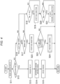
- Fig. 4 is a flowchart illustrating processes related to the engine 4.
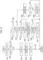
- Fig. 5 is a flowchart illustrating processes related to the motor 5 and the brakes (friction brake system 3). The control process of Fig. 4 and the control process of Fig. 5 are not performed one at a time in sequential order but so that proceed nearly simultaneously.
- Step S11 of Fig. 4 the controller 20 reads inputs from the various sensors and the switch.
- Step S12 the controller 20 determines whether the driver is depressing the accelerator pedal 18. This determination is performed on the basis of the signal of the accelerator opening degree sensor 54.
- Step S12 When a determination result of Step S12 is Yes, that is, when the driver is depressing the accelerator pedal 18, the controller 20 causes the control process to go to Step S13.
- Step S12 When the determination result of Step S12 is No, that is, when the driver is not depressing the accelerator pedal 18, the controller 20 causes the control process to go to Step S16.
- Step S11 is identical to that of Step S31 of Fig. 5 .
- a content of Step S12 is identical to that of Step S32 of Fig. 5 .
- Step S11 and Step S31, and Step S12 and Step S32 are illustrated in independent flowcharts. However, the steps are performed not as independent steps but as common processes to the engine 4, the motor 5, and the friction brake system 3.
- Step S32 determines whether the driver is depressing the accelerator pedal 18 is the driver is depressing the accelerator pedal 18.
- the controller 20 causes the control process to go to Step S33.
- Step S36 determines whether the driver is not depressing the accelerator pedal 18.
- Steps S13 to S15 of Fig. 4 and Steps S31 to S33 of Fig. 5 are processes mainly performed during an acceleration request to the motor vehicle 1. That is, when moving to Step S13 and Step S33, the controller 20 determines to accelerate the motor vehicle 1 and performs control corresponding to the determination.
- Step S13 of Fig. 4 the controller 20 engages both the K0 clutch 6 and the K1 clutch 8d.
- the controller 20 performs this engagement by controlling the first hydraulic circuit 13 and the second hydraulic circuit 8e. It is noted that when both the K0 clutch 6 and the K1 clutch 8d are already engaged, the controller 20 maintains the engagement.
- Step S14 the controller 20 determines a driving force exerted on the engine 4 and the motor 5 entirely on the basis of a depression amount of the accelerator pedal 18, the vehicle velocity at a current moment, and the like. This determination is performed on the basis of the signal of the accelerator opening degree sensor 54, the signal of the vehicle velocity sensor 51, and the like. The controller 20 further determines a driving force to be exerted on the engine 4 on the basis of the driving force determined as described above.
- Step S15 the controller 20 determines a fuel injection amount and the like for realizing the driving force determined in Step S14 and controls the engine 4 on the basis of various parameters determined in that way.
- Step S33 in Fig. 5 a content of Step S33 in Fig. 5 is identical to that of Step S13 described above.
- Step S33 and Step S13 are illustrated in the independent flowcharts. However, the steps are performed not as independent steps but as common processes to the engine 4, the motor 5, and the friction brake system 3.
- Step S14 the controller 20 determines the driving force exerted on the engine 4 and the motor 5 entirely on the basis of the depression amount of the accelerator pedal 18, the vehicle velocity at the current moment, and the like. This process is performed commonly to the process of Step S14 described above.
- the controller 20 further determines a driving force to be exerted on the motor 5 on the basis of the driving force determined as described above.
- Step S35 the controller 20 determines control parameters of the motor 5 for realizing the driving force determined in Step S34 and controls the motor 5 to perform the powering operation on the basis of the various parameters determined in that way.
- Steps S16 to S24 of Fig. 4 and Steps S36 to S45 of Fig. 5 are processes mainly performed during a non-acceleration request to the motor vehicle 1 (particularly during vehicle deceleration).
- the controller 20 performs a process in response to a situation of operating the brake pedal 19 and the like. Processes performed during the non-acceleration request when the brake pedal 19 is not depressed (when the brake pedal 19 is not operated) will be mainly described.
- Step S16 the controller 20 determines whether the air conditioner 72 is turned off. This determination is performed on the basis of the signal of the A/C switch 71.
- Step S16 When a determination result of Step S16 is Yes, that is, when the air conditioner 72 is turned off (when the air conditioner 72 is not driven), the controller 20 causes the control process to go to Step S17.
- Step S16 When the determination result of Step S16 is No, that is, when the air conditioner 72 is turned on, the controller 20 goes to the control process in Step S18.
- Step S17 the controller 20 determines whether the drives is depressing the brake pedal 19. This determination is performed on the basis of the signal of the brake pedal sensor 53.
- Step S17 a determination result of Step S17 is Yes, that is, when the driver is depressing the brake pedal 19, the controller 20 causes the control process to go to Step S22.
- Step S17 No, that is, when the driver is not depressing the brake pedal 19, the controller 20 causes the control process to go to Step S18.
- Step S22 When the controller 20 goes to Step S22, then fuel injection is stopped in the engine 4, and the cooperative regenerative braking control is performed in the motor 5 and the friction brake system 3 depending on the vehicle velocity. This control is performed in a state of releasing the K0 clutch 6, depending on a situation of operating the A/C switch 71.
- Step S18 the motor vehicle 1 decelerates more slowly than when the brake pedal 19 is operated.
- the controller 20 performs a process considering inhibition of engine stalling or the like.
- Step S18 the controller 20 determines whether the engine revolution speed (Ne) is higher than a predetermined first threshold (N1) (Ne > N1?). This determination is performed on the basis of the signal of the engine revolution sensor 55.
- Step S18 When a determination result of Step S18 is Yes, that is, when the engine revolution speed is higher than the first threshold, the controller 20 goes to the control process in Step S19.
- Step S19 the controller 20 stops the fuel injection of the engine 4 and then causes the control process to go to Step S20.
- Step S18 determines whether the engine revolution speed is equal to or lower than the first threshold.
- the controller 20 causes the control process to skip Step S19 and to go to the control process in Step S20.
- the controller 20 controls the fuel injection of the engine 4 to continue. This can inhibit the engine stalling accompanying the deceleration.
- Step S20 the controller 20 determines whether the motor revolution speed (Nm) is lower than a predetermined second threshold (N2) (Nm ⁇ N2?). This determination is performed on the basis of the signal of the motor revolution sensor 56.
- Step S20 When a determination result of Step S20 is Yes, that is, when the motor revolution speed is lower than the second threshold, the controller 20 causes the control process to go to Step S21.
- Step S21 When the controller 20 goes to Step S21 and the fuel injection is stopped in Step S19 described above, the controller 20 also resumes the fuel injection.
- Step S40 of Fig. 5 the controller 20 controls the K1 clutch 8d to slip along with the resume of the fuel injection. By controlling in this way, the engine stalling can be inhibited.
- Step S20 when the determination result of Step S20 is No, that is, when the motor revolution speed is equal to or higher than the second threshold, the controller 20 causes the control process to skip Step S21 and to return to the control processes.
- Step S36 the controller 20 determines whether the vehicle velocity (Vv) of the motor vehicle 1 is higher than a predetermined first velocity (V1) (Vv ⁇ V1?). This determination is performed on the basis of the signal of the vehicle velocity sensor 51.
- Step S36 When a determination result of Step S36 is No, that is, when the vehicle velocity is equal to or lower than the first velocity, the controller 20 causes the control process to go to a point after Step S35. In this case, the controller 20 causes the control process to return without performing special processes.
- Step S36 determines whether the driver is depressing the brake pedal 19. This determination is performed on the basis of the signal of the brake pedal sensor 53.
- Step S37 When a determination result of Step S37 is Yes, that is, when the driver is depressing the brake pedal 19, the controller 20 causes the control process to go to Step S41.
- Step S37 When the determination result of Step S37 is No, that is, when the driver is not depressing the brake pedal 19, the controller 20 causes the control process to go to Step S38.
- Step S41 When the controller 20 goes to Step S41, then the cooperative regenerative braking control is performed in the motor 5 and the friction brake system 3, and fuel injection is stopped in the engine 4 depending on the situation of operating the A/C switch 71. These pieces of control can be performed in the state of releasing the K0 clutch 6.
- Step S42 when the controller 20 goes not to Step S42 but to Step S38, the motor vehicle 1 decelerates more slowly than when the brake pedal 19 is operated. In this case, the controller 20 performs a process considering inhibition of engine stalling or the like.
- Step S38 the controller 20 initiates second regenerative braking control for performing regenerative braking corresponding to the engine braking.
- This second regenerative braking control is the regenerative braking control performed during the deceleration of the motor vehicle 1 when the friction brake system 3 does not apply the braking force to the front wheels 2F and the rear wheels 2R, and is so-called "motor regeneration" for applying a regenerative braking torque to the rear wheels 2R by causing the motor 5 to perform the regenerative operation.
- Step S38 After initiating the second regenerative braking control in Step S38, the controller 20 monitors the motor revolution speed. In Step S39 following Step S38, the controller 20 determines whether the motor revolution speed (Nm) is lower than the predetermined second threshold (N2) (Nm ⁇ N2?). This determination is performed on the basis of the signal of the motor revolution sensor 56.
- Step S39 When a determination result of Step S39 is Yes, that is, when the motor revolution speed is lower than the second threshold, the controller 20 causes the control process to go to Step S40.
- the controller 20 controls the K1 clutch 8d to slip (K1 slip).
- the controller 20 ends the second regenerative braking control (motor regeneration) initiated in Step S38 described above. By controlling in this way, the engine stalling can be avoided.
- Step S39 determines whether the motor revolution speed is equal to or higher than the second threshold.
- Step S22 of Fig. 4 the controller 20 causes the control process to go to Step S22 of Fig. 4 and that in Step S41 of Fig. 5 . Processes in these cases will be described hereinafter.
- Step S22 corresponding to the control process associated with the engine 4, the controller 20 stops the fuel injection of the engine 4.
- the engine revolution speed thereby reaches zero.
- the controller 20 performs the cooperative regenerative braking control described above via the motor 5 and the friction brake system 3 in the state of releasing the K0 clutch 6 as needed.
- the controller 20 stops the fuel injection of the engine 4 while controlling the motor 5 and the friction brake system 3 to continue the cooperative regenerative braking control.
- Step S23 the controller 20 determines whether the start of the engine 4 is requested during the cooperative regenerative braking control.
- the controller 20 determines that the start of the engine 4 is requested when the steering angle exceeds a predetermined value ( ⁇ ) during the cooperative regenerative braking control or when the A/C switch (air conditioner switch) 71 is turned on during the cooperative regenerative braking control.
- the former determination is performed on the basis of the signal of the steering angle sensor 52.
- Step S23 when a determination result of Step S23 is Yes, the controller 20 causes the control process to go to Step S24.
- the controller 20 causes the control process associated with the motor 5 and the friction brake system 3 to go to Step S45 of Fig. 5 corresponding to Step S24.
- Step S24 the controller 20 performs restart control under which the engine 4, the motor 5, and the friction brake system 3 work together.
- the controller 20 returns to the control processes upon completion of this restart control.
- Step S23 when the determination result of Step S23 is No, the controller 20 causes the control process to skip Step S24 and to return. In this case, the controller 20 does not perform the restart control.
- Step S41 corresponding to the control process associated with the motor 5 and the friction brake system 3, the controller 20 determines whether the air conditioner 72 is turned off. This determination is performed on the basis of whether the A/C switch 71 accepts the ON-operation and eventually on the basis of the signal of the A/C switch 71.
- Step S41 determines whether the air conditioner 72 is turned off (when the air conditioner 72 is not driven).
- the controller 20 causes the control process to go to Step S42.
- Step S42 the controller 20 releases the K0 clutch 6.
- the power transmission between the engine 4 and the motor 5 is thereby interrupted.
- the controller causes the control process to go to Step S43 to initiate the cooperative regenerative braking control.
- Step S41 determines whether the air conditioner 72 is turned on (when the A/C switch 71 accepts the ON-operation).
- the controller 20 skips Step S42 and goes to the control process in Step S43. That is, when the brake pedal 19 is depressed and the A/C switch 71 accepts the ON-operation, the controller 20 initiates the cooperative regenerative braking control without releasing the K0 clutch 6.
- Step S43 the controller 20 performs the cooperative regenerative braking control that the regenerative braking torque of the motor 5 makes up for part of the driver's requested braking force. It is noted that the fluid pressure of each friction brake 31 is reduced by as the amount of the regenerative braking torque of the motor 5. The braking force resulting from the friction brake system 3 is reduced by as much as the reduction in the fluid pressure of the friction brakes 31.
- Step S44 the controller 20 determines whether the start of the engine 4 is requested during the cooperative regenerative braking control.
- Step S44 is identical to that of Step S23 of Fig. 4 .
- Step S44 and Step S23 are illustrated in the independent flowcharts. However, the steps are performed not as independent steps but as common processes to the engine 4, the motor 5, and the friction brake system 3.
- Step S44 when a determination result of Step S44 is Yes, the controller 20 causes the control process to go to Step S45 to perform the restart control. The controller 20 causes the control process to return upon completion of this restart control.
- Step S44 determines whether the determination result of Step S44 is No.
- the controller 20 causes the control process to skip Step S45 and to return. In this case, the controller 20 does not perform the restart control.
- Fig. 6 is a flowchart illustrating processes associated with the restart control.
- the controller 20 performs a first process of transitioning from braking by the cooperative regenerative braking control to braking only by the friction brake system 3.
- the controller 20 switches from the braking by the cooperative regenerative braking control to the braking only by the friction brake 31.
- the requested braking force including the braking force the regenerative braking torque of the motor 5 makes up for so far, is made up for entirely by the friction brake system 3.
- Step S51 the controller 20 increases the braking force by the friction brakes 31 to make up for the braking force the regenerative braking torque of the motor 5 makes up for so far.
- the controller 20 increases the fluid pressure of each friction brake 31 by as the amount of the regenerative braking torque of the motor 5.
- the braking force resulting from the friction brake system 3 is increased by as much as the increase in the fluid pressure of the friction brakes 31.
- Step S52 following Step S51 the controller 20 determines whether the transition to the braking only by the friction brake system 3 is completed. This determination is performed on the basis of the signal of the brake fluid pressure sensor 57.
- Steps S53 to 55 the controller 20 performs, after the completion of the transition to the braking only by the friction brake system 3, a second process of increasing the engine revolution speed by controlling the motor 5 to perform the powering operation or the regenerative operation while initiating the engagement of the K0 clutch 6.
- Step S53 the controller 20 determines whether the K0 clutch 6 is released.
- Step S53 determines whether the K0 clutch 6 is released.
- the controller 20 causes the control process to go to Step S55 by way of Step S54.
- the controller 20 causes the control process to skip Step S54 and to go to Step S55.
- Step S54 the controller 20 initiates the engagement of the K0 clutch 6 by hydraulically controlling the first hydraulic circuit 13.
- the K0 clutch 6 is engaged while slipping.
- the K0 clutch 6 is gradually engaged via Step S54, or the K0 clutch 6 is already engaged as in the case of skipping Step S54, whereby the motor 5 drives the crankshaft 4a to rotate.
- the engine revolution speed may be increased by transmitting the regenerative operation of the motor 5 to the crankshaft 4a or by transmitting the powering operation of the motor 5 to the crankshaft 4a.
- the engagement with the engine 4 is a rotational resistance for the motor 5. This is why, when the K0 clutch 6 is engaged to initiate the rise of the engine revolution speed, the motor revolution speed and eventually the vehicle velocity are gradually reduced. To address this, an output torque of the motor 5 may be gradually increased by causing the motor 5 to perform the powering operation as the engine revolution speed increases.
- Step S55 start of the engine 4 (an increase in the engine revolution speed) is initiated by transmitting the rotation of the motor 5 to the engine 4. It is noted that in Step S55, the motor 5 is used not for control over the driving force for outputting the running driving force of the motor vehicle 1 but for the start control of the increase of the engine revolution speed.
- the controller 20 performs a third process of controlling the engine 4 to resume operating at the timing after the engine revolution speed rises to match the motor revolution speed after the engagement of the K0 clutch 6 is initiated.
- Step S56 When a determination result of Step S56 is Yes, the controller 20 causes the control process to go to Step S59. In Step S59, the controller 20 determines that the start of the engine 4 is completed.
- Step S56 the controller 20 causes the control process to go to Step S57.
- Step S57 the controller 20 determines whether the motor revolution speed is below the predetermined second threshold (N2) (Nm ⁇ N2?). This determination is performed on the basis of the signal of the motor revolution sensor 56.
- Step S57 When a determination result of Step S57 is No, the controller 20 causes the control process to skip subsequent Step S58 and to go back to Step S56. That is, the determination of Step S57 is repeatedly performed until the engine revolution speed matches the motor revolution speed.
- Step S57 the controller 20 causes the control process to go to Step S58.
- Step S58 the controller 20 controls the K1 clutch 8d to slip (K1 slip) for interrupting or relaxing the power transmission between the axle and the motor 5.
- controller 20 is configured to control the K1 clutch 8d to slip when the output revolution speed of the motor 5 falls to be lower than the second threshold that is the predetermined revolution speed after the engagement of the K0 clutch 6 is initiated in the second process.
- Step S59 following the case where the determination result of Step S56 is Yes, the controller 20 determines that the start of the engine 4 is completed as described above. Therefore, in subsequent Step S60, the controller 20 resumes the fuel injection of the engine 4. The engine 4 thereby resumes operating.
- Step S60 the engine 4 and the motor 5 work together to output the running driving force of the motor vehicle 1.
- the controller 20 controls the engine 4 and the motor 5 so that the deceleration corresponding to the depression amount of the brake pedal 19 can be realized. Nevertheless, the transient or long-term deceleration possibly causes the engine stalling.
- Step S61 the controller 20 determines whether the engine revolution speed and the motor revolution speed are lower than a predetermined idle revolution speed (e.g., the second threshold) (Ne ⁇ N2? or Nm ⁇ N2?).
- a predetermined idle revolution speed e.g., the second threshold
- Step S61 the controller 20 controls the K1 clutch 8d to be released or slip.
- the controller 20 adjusts output torques of the engine 4 and the motor 5 in addition to controlling the K1 clutch 8d to be released or slip, maintaining the engine revolution speed or the motor revolution speed to be equal to or higher than the predetermined revolution speed.
- the controller 20 may increase a fuel injection amount of the engine 4.
- the controller 20 may assist the idle control by strengthening the powering operation of the motor 5 or weakening the regenerative operation of the motor 5.
- the controller 20 performs the idle control over the engine 4 so that the output revolution speeds of the engine 4 and the motor 5 rise to be equal to or higher than the idle revolution speed along with the release or the slip of the K1 clutch 8d.
- This time chart contains a cooperative regeneration flag, a steering angle flag, a restart flag, a situation of operating the accelerator pedal 18, a situation of operating the brake pedal 19, a change in the vehicle velocity, a change in the motor revolution speed, and a change in the engine revolution speed.
- the cooperative regeneration flag is set to 1 when it is determined to perform the cooperative regenerative braking control.
- the steering angle flag is set to 1 when the signal of the steering angle sensor 52 is detected (when the steering wheel 110 is operated).
- the restart flag is set to 1 when it is determined to perform the restart control.
- the situation of operating the accelerator pedal 18 is set to ON when the accelerator pedal 18 is operated and to OFF when the accelerator pedal 18 is not operated.
- the situation of operating the brake pedal 19 is set to ON when the brake pedal 19 is operated and to OFF when the brake pedal 19 is not operated.
- the vehicle velocity falls relatively abruptly since the engine 4 is stopped and the brake pedal 19 is depressed.
- the cooperative regeneration flag is set to 1 to initiate the cooperative regenerative braking control.
- the entire requested braking force is realized by cooperation between the motor 5 and the friction brake system 3. At the same time, the motor 5 generates electric power.
- the driver operates the steering wheel 110 at a time t1. It is determined from this operation that the restart of the engine 4 was requested.
- the steering angle flag is set to 1 on the basis of this determination, and the braking by the cooperation between the motor 5 and the friction brake system 3 is switched to the braking only by the friction brake system 3 (first process).
- the restart flag is set to 1 in response to the switching completion.
- the restart flag is set to 1 to initiate the engagement of the K0 clutch 6, the rise of the engine revolution speed is initiated by receiving the power from the motor 5 (second process). As the engine revolution speed rises, the motor revolution speed continues to fall.
- the K1 clutch 8d is made to slip. Slipping of the K1 clutch 8d causes the motor revolution speed to start rising to be kept equal to or higher than the second threshold.
- the slipping of the K1 clutch 8d is performed after the completion of the switching to the braking only by the friction brake system 3 in the present embodiment.
- the K1 clutch 8d When the timing of slipping the K1 clutch 8d is not associated with the timing of switching of braking as in the conventionally known configurations, the K1 clutch 8d may be caused to slip while the switching of the braking is not completed yet. In this case, the regenerative operation is performed in a state of inhibiting the power transmission between the motor 5 and the rear wheels 2R. As a result, the output torque (regenerative braking torque) of the motor 5 may be transmitted to the rear wheels 2R insufficiently, and the G drop possibly occurs.
- the K1 clutch 8d is made to slip after the completion of the switching of braking.
- the slipping of the K1 clutch 8d is thereby initiated in a state of finishing applying the regenerative braking torque (e.g., in a state of reducing the regenerative braking torque to nearly zero). This can inhibit the occurrence of the G drop.
- the controller 20 completes the restart of the engine 4.
- the controller 20 then resumes the fuel injection of the engine 4, allowing the engine 4 to resume operating (third process).
- the motor 5 performs the regenerative operation during the deceleration of the motor vehicle 1 when the friction brake system 3 distributes the braking force to the rear wheels 2R.
- This control is the cooperative regenerative braking control by the friction brake system 3 and the motor 5.
- the cooperative regenerative braking control increases the regenerative energy accumulated in the high-voltage battery 9.
- the regenerative braking torque by the motor 5 is applied to the rear wheels 2R serving as the driving wheels.
- the friction brake system 3 distributes the braking force to the rear wheels 2R in consideration of the regenerative braking torque applied to the rear wheels 2R.
- the braking acting on the motor vehicle 1 is in response to the driver's operating the brake pedal 19.
- the controller 20 controls the distribution of the braking force so that desired braking (braking in response to the operation of the brake pedal 19) can be realized by the regenerative braking torque and the braking force.
- Steps S52 and S55 of Fig. 6 when the start of the engine 4 is requested during the cooperative regenerative braking control, the controller 20 raises the output revolution speed of the engine 4 after the completion of the transition from the braking by the cooperative regenerative braking control to the braking only by the friction brake system 3.
- Step S61 of Fig. 6 the engine revolution speed is, possibly, continuously controlled by the idle control or the like even after being adjusted. Therefore, controlling the start of the engine 4 to be initiated after switching the braking can separate the processes associated with the output revolution speeds such as the idle control from the processes associated with the switching of the braking. The processes such as the idle control can be thereby inhibited from affecting the switching of the braking.
- the controller 20 controls the K1 clutch 8d to slip when the predetermined condition is satisfied.
- Making the K1 clutch 8d to slip can reduce the rotational resistance of the motor 5. This can inhibit the reduction in the output revolution speed of the motor 5.
- the K1 clutch 8d may be slipped while the switching of the braking is not completed yet.
- the regenerative operation is performed in the state of inhibiting the power transmission between the motor 5 and the rear wheels 2R.
- the regenerative braking torque applied by the motor 5 may be transmitted to the rear wheels 2R insufficiently, and the G drop possibly occurs.
- the K1 clutch 8d is made to slip after the switching of the braking ends, as illustrated in the temporal relationship between Steps S52 and S58 of Fig. 6 and the temporal relationship between the times t2 and t3 of Fig. 7 .
- the slipping of the K1 clutch 8d is thereby initiated in a state of finishing applying the regenerative braking torque (e.g., in a state of reducing the regenerative braking torque to nearly zero). This can inhibit the occurrence of the G drop.
- the output revolution speeds of the engine 4 and the motor 5 can be kept equal to or higher than the idle revolution speed after the engine 4 restarts. This enables smooth acceleration of the motor vehicle 1 when the motor vehicle 1 is requested to accelerate such as when the depression of the brake pedal 19 is transitioned to the depression of the accelerator pedal 18.
- the controller 20 performs the first process, the second process, and the third process described above when the steering wheel 110 is operated during the deceleration when the brake pedal 19 is depressed (that is, while the cooperative regenerative braking control is being performed).
- This enables smooth restart of the engine 4 without causing a problem such as the G drop when, for example, the motor vehicle 1 enters a corner with the brake pedal 19 depressed. That can realize so-called slow-in fast-out more smoothly than conventional hybrid vehicles. Operability of the hybrid vehicle can be thereby enhanced.
- the controller 20 performs the first process, the second process, and the third process described above when the A/C switch 71 is operated during the deceleration when the brake pedal 19 is depressed (that is, while the cooperative regenerative braking control is being performed).
- This enables the smooth restart of the engine 4 without causing a problem such as the G drop when, for example, the air conditioner 72 is desired to be driven during the depression of the brake pedal 19. That can inhibit the occurrence of a shock when the engine restarts. Ride quality of the hybrid vehicle can be thereby enhanced.
Landscapes
- Engineering & Computer Science (AREA)
- Transportation (AREA)
- Mechanical Engineering (AREA)
- Chemical & Material Sciences (AREA)
- Combustion & Propulsion (AREA)
- Automation & Control Theory (AREA)
- Physics & Mathematics (AREA)
- Mathematical Physics (AREA)
- Hybrid Electric Vehicles (AREA)
- Electric Propulsion And Braking For Vehicles (AREA)
Abstract
Description
- The present invention relates to a control system for a hybrid vehicle.
- For example,
Patent Document 1 discloses a control system for a hybrid vehicle. This hybrid vehicle is a vehicle having a so-called P2 module onboard. - Specifically, the hybrid vehicle disclosed in
Patent Document 1 includes an engine, a first friction clutch element, a motor generator engaged with the engine via the first friction clutch element, a second friction clutch element that lies between the motor generator and driving wheels, and a cooperative regenerative braking control execution unit. - The cooperative regenerative braking control execution unit disclosed in
Patent Document 1 prohibits a regenerative torque from increasing until predetermined time passes since engaging the friction clutch element when a mechanical brake is operated and the friction clutch element is in a state of slipping (e.g., at a time of start of the engine). According toPatent Document 1, the prohibition of the increase of the regenerative torque enables the prevention of occurrence of a shock caused by an unintended slippage. - [Patent document 1]
JP-A-2012-091551 - Meanwhile, for the hybrid vehicle having the P2 module onboard as disclosed in
Patent Document 1, the cooperative regenerative braking control is normally performed in a state of releasing a clutch that lies between the engine and the motor during the operation of the brake pedal. This cooperative regenerative braking control is to brake the driving wheels by cooperation between application of a braking force from a brake system and a regenerative operation by the motor. - Subsequently, when the vehicle enters a curve, it is often requested to restart the engine despite operating the brake pedal (that is, during the cooperative regenerative braking control), such as when an air conditioner is actuated during deceleration.
- In this case, it is considered to switch from braking by the cooperative regenerative braking control to braking using only the brake system and couple the engine to the motor by engaging the clutch for increasing an output revolution speed of the engine.
- However, when a hydraulic brake system is used, the switching of the braking cannot be performed momentarily. Furthermore, it takes some time to couple the engine to the motor since the engagement of the clutch until the output revolution speed of the engine matches that of the motor.
- Therefore, if the switching of the braking and the clutch engagement are initiated nearly simultaneously, two processes proceed nearly simultaneously. In this case, a situation of adjusting the output revolution speeds, such as a change in the regenerative operation of the motor when the output revolution speed of the engine does not have a smooth transition, may affect the cooperative regenerative braking control and the switching of the braking from the cooperative regenerative braking control.
- For example, when the rise of the output revolution speed of the engine delays, it is required to cause the motor in the regenerative operation to perform a powering operation and to weaken a regenerative force (regenerative braking torque) by the motor. These types of processing inconveniently complicate the cooperative regenerative braking control.
- The present invention has been made in light of these problems and an object of the present invention is to inhibit clutch engagement at the time of restart of an engine from affecting cooperative regenerative braking control and switching of braking in a hybrid vehicle having a P2 module onboard.
- The present invention relates to a control system for a hybrid vehicle including: an engine that generates a vehicle running driving force of the hybrid vehicle; a motor capable of performing a powering operation and a regenerative operation; a first clutch that lies between the engine and the motor and that is switched between a connection state of mutual engagement between the engine and the motor and a separation state of releasing the engagement; and an axle that lies between the motor and driving wheels of the vehicle. This control system includes: a hydraulic frictional brake system that distributes a braking force to the driving wheels in response to driver's operating a brake pedal; and a control unit capable of performing cooperative regenerative braking control for braking the hybrid vehicle by cooperation between distribution of the braking force by the frictional brake system and application of a regenerative braking torque to the driving wheels by controlling the motor to perform the regenerative operation in a state of disengaging the first clutch during deceleration of the vehicle when operating the brake pedal.
- Furthermore, according to one aspect of the present invention, when start of the engine is requested during the cooperative regenerative braking control, the control unit performs: a first process of transitioning braking by the cooperative regenerative braking control to braking only by the frictional brake system; a second process of raising an output revolution speed of the engine by controlling the motor to perform either the powering operation or the regenerative operation while initiating engagement of the first clutch after completion of transitioning to the braking only by the frictional brake system; and a third process of controlling the engine to resume operating at timing after the output revolution speed of the engine rises to match an output revolution speed of the motor after the engagement of the first clutch is initiated.
- According to these configurations, the hybrid vehicle is a hybrid vehicle having a so-called P2 module onboard in which the engine, the first clutch, the motor, a second clutch, the axle, and the driving wheels are coupled to transmit the running driving force thereto in this order.
- Furthermore, during deceleration of the hybrid vehicle in which the frictional brake system is distributing the braking force to the driving wheels, the motor performs the regenerative operation. This control is the cooperative regenerative braking control between the frictional brake system and the motor. The cooperative regenerative braking control increases regenerative energy accumulated in a battery or the like. The regenerative braking torque by the motor is applied to the driving wheels. The frictional brake system distributes the braking force to the driving wheels in consideration of the regenerative braking torque applied to the driving wheels. As a result, the braking acting on the hybrid vehicle is braking responsive to driver's operating the brake pedal.
- Here, the control unit raises the output revolution speed of the engine after completion of transitioning from the braking by the cooperative regenerative braking control to the braking only by the frictional brake system when the start of the engine is requested during the cooperative regenerative braking control.
- Therefore, when adjustment of the output revolution speed of the engine is initiated, switching of the braking is already completed. As a result, it is possible to inhibit the situation of adjusting the output revolution speeds from affecting the cooperative regenerative braking control and the switching of the braking from the cooperative regenerative braking control.
- Moreover, according to one aspect of the present invention, the control system for the hybrid vehicle may include a second clutch that lies between the motor and the axle and that is switched between a connection state of mutual engagement between the motor and the axle and a separation state of releasing the engagement, the second clutch may be engaged when the cooperative regenerative braking control is performed, and the control unit may control the second clutch to slip when the output revolution speed of the motor falls below a predetermined revolution speed after the engagement of the first clutch is initiated in the second process.
- According to these configurations, the second clutch is made to slip when a predetermined condition is satisfied. Making the second clutch to slip can reduce a rotational resistance of the motor. This, in turn, can inhibit a reduction in the output revolution speed of the motor.
- Here, when the timing of slipping the second clutch is not associated with the timing of switching to the braking only by the frictional brake system as in conventionally known configurations (e.g., when two processes are initiated simultaneously), the second clutch may be made to slip while the switching of the braking is not completed yet.
- In this case, the regenerative operation is performed in a state of suppressing power transmission between the motor and the driving wheels. As a result, the regenerative braking torque applied from the motor is insufficiently transmitted to the driving wheels, possibly causing a G drop.
- On the other hand, with the configurations described above, the second clutch is made to slip after finishing the switching of the braking. As a result, slipping of the second clutch is initiated in a state in which the regenerative braking torque has been applied to the driving wheels (e.g., in a state of reducing the regenerative braking torque to nearly zero). This can inhibit the occurrence of the G drop.
- Furthermore, according to one aspect of the present invention, the control unit may control the second clutch to be released or slip and control the engine to raise the output revolution speed of the engine to be equal to or higher than a predetermined idle revolution speed when the output revolution speeds of the engine and the motor fall below the idle revolution speed after the output revolution speed of the engine is made to match the output revolution speed of the motor in the third process.
- According to the configurations, the output revolution speeds of the engine and the motor can be kept equal to or higher than the idle revolution speed after the engine restarts. This enables smooth acceleration of the hybrid vehicle when the hybrid vehicle is requested to accelerate such as when depression of the brake pedal is transitioned to depression of an accelerator pedal.
- Moreover, according to one aspect of the present invention, the control unit may determine that the start of the engine is requested when a steering angle exceeds a predetermined value during the cooperative regenerative braking control.
- According to the configurations, the control unit performs the first process, the second process, and the third process when a steering wheel is operated during deceleration when the brake pedal is depressed (that is, while the cooperative regenerative braking control is being performed). This enables smooth restart of the engine without causing a problem such as the G drop when, for example, the hybrid vehicle enters a corner with the brake pedal depressed. That can realize so-called slow-in fast-out more smoothly than conventional hybrid vehicles. Operability of the hybrid vehicle can be thereby enhanced.
- Furthermore, according to one aspect of the present invention, the control unit may determine that the start of the engine is requested when an air conditioner switch accepts an ON-operation during the cooperative regenerative braking control.
- According to the configurations, the control unit performs the first process, the second process, and the third process when the air conditioner switch is operated during deceleration when the brake pedal is depressed (that is, while the cooperative regenerative braking control is being performed). This enables smooth restart of the engine without causing a problem such as the G drop when, for example, an air conditioner is desired to be driven during the depression of the brake pedal. That can inhibit the occurrence of a shock when the engine restarts. Ride quality of the hybrid vehicle can be thereby enhanced.
- As described so far, according to the present invention, it is possible to inhibit the clutch engagement during the engine restart from affecting the cooperative regenerative braking control and the switching of the braking in the hybrid vehicle with the P2 module onboard.
-
- [
Fig. 1] Fig. 1 illustrates a hybrid vehicle. - [
Fig. 2] Fig. 2 illustrates an automatic transmission engagement table. - [
Fig. 3A] Fig. 3A is a block diagram of a control system for the hybrid vehicle. - [
Fig. 3B] Fig. 3B is a block diagram of a friction brake system. - [
Fig. 4] Fig. 4 is a flowchart illustrating processes related to an engine. - [
Fig. 5] Fig. 5 is a flowchart illustrating processes related to a motor and brakes. - [
Fig. 6] Fig. 6 is a flowchart illustrating processes related to restart control. - [
Fig. 7] Fig. 7 is a time chart of a first process, a second process, and a third process. - Embodiments of a control system for a hybrid vehicle will be described hereinafter. The following descriptions are given by way of example.
-
Fig. 1 illustrates a motor vehicle 1 (an example of a vehicle and a hybrid vehicle) to which the present invention is applied. Thismotor vehicle 1 is a hybrid vehicle capable of running using electricity. Themotor vehicle 1 hasfront wheels 2F andrear wheels 2R, i.e., four wheels in total. Afriction brake 31 is attached to each of thefront wheels 2F and therear wheels 2R for braking a rotation thereof. - As drive sources, an
engine 4 generating a running driving force of themotor vehicle 1 and amotor 5 are onboard themotor vehicle 1. These work together to drive therear wheels 2R. Themotor vehicle 1 thereby runs. Themotor vehicle 1 is a rear-wheel drive vehicle. Themotor 5 is used not only as the drive source but also as an electric generator during regeneration. That is, themotor 5 according to the present embodiment can perform a powering operation for generating the running driving force of themotor vehicle 1 and a regenerative operation for supplying regenerative energy to a battery (high-voltage battery 9 to be described later) when decelerating themotor vehicle 1. - This
motor vehicle 1 has the high-voltage battery 9 at a rated voltage equal to or lower than 50V onboard, as described later. The electricity is supplied to the motor from the high-voltage battery 9, and themotor 5 functions to allow themotor vehicle 5 to run mainly in the way of assisting theengine 4. Themotor vehicle 1 is a so-called mild hybrid vehicle. It is noted that themotor vehicle 1 may be a so-called plug-in hybrid vehicle to which the electricity can be supplied from an external power supply. - Furthermore, the
motor vehicle 1 is a hybrid vehicle having a so-called P2 module onboard so that theengine 4, a first clutch (K0 clutch 6), themotor 5, a second clutch (K1 clutch 8d), an axle (drive shafts 17), and driving wheels (rear wheels 2R) are coupled to transmit the running driving force thereto in this order. - In the case of this
motor vehicle 1, theengine 4 is disposed on a front side of a vehicle body, and the driving wheels are disposed on a rear side of the vehicle body. That is, thismotor vehicle 1 is a so-called FR vehicle. - As devices in a driving system, the
K0 clutch 6, aninverter 7, and anautomatic transmission 8, as well as theengine 4 and themotor 5, are onboard themotor vehicle 1. In addition, acontroller 20 as a device in a control system is onboard themotor vehicle 1. Furthermore, a hydraulicfriction brake system 3 including thefriction brakes 31 is onboard themotor vehicle 1 as a device in a braking system. - The
engine 4 is, for example, an internal combustion engine that burns a fossil fuel. Theengine 4 is also a so-called four-cycle engine in which rotational power is generated by repeating cycles of intake, compression, expansion, and exhaust. While being configured as a diesel engine classified into a compression-ignition engine, theengine 4 may be of various types in various forms, such as a spark-ignition engine and other compression-ignition engines. Theengine 4 operates by injecting a fuel such as fossil fuel and burning the fuel in cylinders. - In this
motor vehicle 1, acrankshaft 4a that outputs rotational power is disposed in a nearly central portion in a vehicle width direction of theengine 4 in a state of being oriented to a front-rear direction of the vehicle body. Various devices and mechanisms associated with theengine 4, such as an intake system, an exhaust system, and a fuel supply system, are installed in themotor vehicle 1. - The
motor 5 is a permanent magnet-type synchronous motor driven by a three-phase alternating-current. Themotor 5 is disposed in the rear of theengine 4 in series via theK0 clutch 6. Themotor 5 is also disposed in front of theautomatic transmission 8 in series. - The
K0 clutch 6 lies between theengine 4 and themotor 5. More specifically, theK0 clutch 6 is installed to lie between a front end portion of ashaft 5a of themotor 5 and thecrankshaft 4a of theengine 4. TheK0 clutch 6 is switched between a state (connection state) in which thecrankshaft 4a is coupled to theshaft 5a and a state (separation state) in which thecrankshaft 4a is separate from theshaft 5a. - The connection state of the
K0 clutch 6 is a state in which theengine 4 is engaged with themotor 5 are engaged. The separation state of theK0 clutch 6 is a state in which the engagement between theengine 4 and themotor 5 is released (disengagement state). The K0 clutch 6 functions as a "first clutch" in the present embodiment. The switching of theK0 clutch 6, which serves as the first clutch, between the connection state and the separation state is performed under hydraulic control of a first hydraulic circuit 13 (illustrated only inFig. 3A ). - A rear end portion of the
shaft 5a of themotor 5 is coupled to aninput shaft 8a of theautomatic transmission 8. Therefore, theengine 4 is coupled to theautomatic transmission 8 via theK0 clutch 6 and theshaft 5a. Setting theK0 clutch 6 into the separation state causes theengine 4 to be disengaged from theautomatic transmission 8. - While the
motor vehicle 1 is on the run, theK0 clutch 6 is switched between the connection state and the separation state. For example, when themotor vehicle 1 decelerates, theK0 clutch 6 is switched to the separation state to often perform regeneration in a state of disengaging theengine 4. For example, in cooperative regenerative braking control to be described later, themotor 5 can perform a regenerative operation in a state of disengaging theK0 clutch 6 serving as the first clutch. In addition, the K1 clutch 8d serving as a second clutch is designed to be engaged when the cooperative regenerative braking control is performed. - The
motor 5 is connected to the high-voltage battery 9 onboard as a driving power supply via theinverter 7 and a high-voltage cable 40. In the case of thismotor vehicle 1, the high-voltage battery 9 is a direct-current battery at a rated voltage equal to or lower than 50V, specifically, 48V. - The high-
voltage battery 9 supplies a high-voltage direct current to theinverter 7. Theinverter 7 converts the direct-current electric power into a three-phase alternating current to energize themotor 5. Themotor 5 is thereby driven to rotate. Furthermore, themotor 5 supplies regenerative energy to the high-voltage battery 9. - The high-
voltage battery 9 is also connected to aDCDC converter 10 via the high-voltage cable 40. TheDCDC converter 10 converts high-voltage direct-current electric power of 48V into low-voltage direct-current electric power of 12V and outputs the low-voltage direct-current electric power of 12V. (An output side) of theDCDC converter 10 is connected to a low-voltage battery 11 (so-called lead storage battery) via a low-voltage cable 41. - The low-
voltage battery 11 is connected to various electric components via the low-voltage cable 41. TheDCDC converter 10 is also connected to a CAN (Controller Area Network) 12 via the low-voltage cable 41. TheDCDC converter 10 thereby supplies low-voltage direct-current electric power to theCAN 12. - The
automatic transmission 8 is a hydraulically controlled, multi-stage automatic transmission (so-called AT). Thisautomatic transmission 8 has theinput shaft 8a connected to theengine 4 and anoutput shaft 8b connected to the driving wheels (rear wheels 2R) of themotor vehicle 1. Thisautomatic transmission 8 can shift a rotation input to theinput shaft 8a at a gear ratio corresponding to a gear position selected by a passenger and output the rotation. - Specifically, the
input shaft 8a is disposed in a front end portion of theautomatic transmission 8. As described above, thisinput shaft 8a is coupled with theshaft 5a of themotor 5. Theoutput shaft 8b is disposed in a rear end portion of theautomatic transmission 8. Thisoutput shaft 8b rotates in a state of being independent of theinput shaft 8a. - A transmission mechanism including a
torque converter 8c, a plurality of planetary gear mechanisms, a plurality of friction clutch elements, and the like is incorporated between theinput shaft 8a and theoutput shaft 8b. Each friction clutch element is hydraulically switched between an engagement state and a disengagement state. -
Fig. 2 illustrates a engagement table of thisautomatic transmission 8. In the table, circles indicate engagement. As the friction clutch elements, three clutches including a first clutch CL1, a second clutch CL2, and a third clutch CL3 and two brakes including a first brake BR1 and a second brake BR2 are incorporated into thisautomatic transmission 8. Theautomatic transmission 8 also has a secondhydraulic circuit 8e (illustrated only inFig. 3A ) for switching these friction clutch elements between the engaged state (connection state) and the disengaged state (separation state). - The
automatic transmission 8 selects and engages three elements from among the three clutches and the two brakes under the hydraulic control of the secondhydraulic circuit 8e. The gear position of theautomatic transmission 8 is thereby switched to any of gear positions from a first gear to an eighth gear for forward driving and a gear position (reverse gear) for backward driving. - Specifically, the first clutch CL1, the first brake BR1, and the second brake BR2 are engaged to form the first gear. The second clutch CL2, the first brake BR1, and the second brake BR2 are engaged to form the second gear. The first clutch CL1, the second clutch CL2, and the second brake BR2 are engaged to form the third gear. The second clutch CL2, the third clutch CL3, and the second brake BR2 are engaged to form the fourth gear. The first clutch CL1, the third clutch CL3, and the second brake BR2 are engaged to form the fifth gear. The first clutch CL1, the second clutch CL2, and the third clutch CL3 are engaged to form the sixth gear. The first clutch CL1, the third clutch CL3, and the first brake BR1 are engaged to form the seventh gear. The second clutch CL2, the third clutch CL3, and the first brake BR1 are engaged to form the eighth gear. The third clutch CL3, the first brake BR1, and the second brake BR2 are engaged to form the reverse gear.
- Then, when up-shifting from, for example, the first gear, the second clutch CL2 is engaged as an alternative to the first clutch CL1 to switch the gear position from the first gear to the second gear. The first clutch CL1 is engaged as an alternative to the first brake BR1 to switch the gear position from the second gear to the third gear. The third clutch CL3 is engaged as an alternative to the first clutch CL1 to switch the gear position from the third gear to the fourth gear.
- Up-shifting to the fifth and higher gears is performed similarly to the above. Down-shifting is performed in opposite procedures to those in the switching for up-shifting.
- When the elements to be engaged are not engaged in each gear position, the
input shaft 8a and theoutput shaft 8b are in a separated state (so-called neutral). Even when the rotational power is input to theautomatic transmission 8 from the drive source, the rotational power is not output from theautomatic transmission 8. - In the present embodiment, the
automatic transmission 8 may be put into neutral by releasing the second clutch CL2 or the third clutch CL3 during the deceleration of themotor vehicle 1. Specifically, when theautomatic transmission 8 is in a state of the second gear, third gear, or fourth gear, theautomatic transmission 8 is put into neutral by releasing the second clutch CL2. In addition, when theautomatic transmission 8 is in a state of the fifth gear, sixth gear, seventh gear, or eighth gear, theautomatic transmission 8 is put into neutral by releasing the third clutch CL3. - In the following descriptions, the second clutch CL2 and the third clutch CL3 are often referred to as "K1 clutch 8d" collectively (refer to
Fig. 3A ). Releasing the K1 clutch 8d during the deceleration of themotor vehicle 1 means that power transmission between theinput shaft 8a and theoutput shaft 8b of theautomatic transmission 8 is interrupted to put theautomatic transmission 8 into neutral. - As illustrated in
Fig. 1 , theoutput shaft 8b of theautomatic transmission 8 is coupled to adifferential gear 16 via a propeller shaft extending in the front-rear direction of the vehicle body. A pair ofdrive shafts rear wheels differential gear 16. The rotational power output through thepropeller shaft 15 is sorted out by thedifferential gear 16 and transmitted to therear wheels 2R through the pair ofdrive shafts drive shafts motor 5 and the driving wheels (left and rightrear wheels - While the
motor vehicle 1 is on the run, the K1 clutch 8d is switched between the connection state and the separation state. Here, the connection state of the K1 clutch 8d is a state in which themotor 5 is engaged with the pair ofdrive shafts motor 5 and the pair ofdrive shafts - The K1 clutch 8d functions as the "second clutch" in the present embodiment. The switching between the connection state and the separation state of the K1 clutch 8d serving as the second clutch is performed under the hydraulic control of the second
hydraulic circuit 8e, as described above. -
Fig. 3A is a block diagram of a control system for the hybrid vehicle. In themotor vehicle 1, thecontroller 20 described above is installed for controlling theengine 4, themotor 5, theK0 clutch 6, theautomatic transmission 8, thefriction brake system 3, and the like in response to a driver's operation and controlling themotor vehicle 1 to run. - The
controller 20 is configured with hardware such as a processor, a memory, and an interface and software such as a database and a control program. It is noted that while onecontroller 20 is illustrated in the control system ofFig. 3A , the controller of the control system may be divided into a unit (PCM) mainly controlling actuation of the drive sources (theengine 4 and the motor 5) and a unit (TCM) mainly controlling actuation of theK0 clutch 6 and theautomatic transmission 8. The PCM and the TCM are connected by theCAN 12 and configured to be capable of electrically communicating with each other. The PCM also functions as a brake ECU for controlling thefriction brake system 3. It is noted that the brake ECU may be separated from the PCM. Thecontroller 20 functions as a "control unit" in the present embodiment. - The control system for the hybrid vehicle includes sensors that measure various parameters related to the running of the vehicle and a switch detecting a driver's operation. Specifically, the control system, i.e., transmission control system includes a
vehicle velocity sensor 51, asteering angle sensor 52, abrake pedal sensor 53, an acceleratoropening degree sensor 54, anengine revolution sensor 55, amotor revolution sensor 56, and an A/C switch 71. - The
vehicle velocity sensor 51 outputs a signal corresponding to a vehicle velocity of themotor vehicle 1. Thesteering angle sensor 52 outputs a signal corresponding to a rotational angle, that is, a steering angle of a steering wheel 110 (refer toFig. 1 ) operated by a driver. - The
brake pedal sensor 53 outputs a signal corresponding to depression of a brake pedal 19 (refer toFig. 1 ) operated by the driver. The acceleratoropening degree sensor 54 outputs a signal corresponding to depression of an accelerator pedal 18 (refer toFig. 1 ) operated by the driver. - The
engine revolution sensor 55 outputs a signal corresponding to the output revolution speed of the engine 4 (engine revolution speed), that is, corresponding to a revolving speed of thecrankshaft 4a. Themotor revolution sensor 56 outputs a signal corresponding to the output revolution speed of the motor 5 (motor revolution speed), i.e., corresponding to a revolution speed of theshaft 5a of themotor 5 and a revolution speed of theinput shaft 8a of theautomatic transmission 8. - The A/
C switch 71 is a switch for switching anair conditioner 72 illustrated only inFig. 3A between an ON-state and an OFF-state. When being operated to be turned on to set theair conditioner 72 into the ON-state by the driver, the A/C switch 71 outputs a signal corresponding to the on operation. - The
controller 20 receives the signals output from the sensors and the switch via theCAN 12. Thecontroller 20 outputs control signals to theengine 4, theinverter 7, the firsthydraulic circuit 13, the secondhydraulic circuit 8e, theair conditioner 72, and thefriction brake system 3 through theCAN 12. Thecontroller 20 thereby controls theengine 4, themotor 5, theK0 clutch 6, theautomatic transmission 8, theair conditioner 72, and thefriction brake system 3. - For example, when the driver performs the ON-operation on the A/
C switch 71 to turn on theair conditioner 72, thecontroller 20 actuates a compressor of theair conditioner 72 using a driving force of theengine 4. - Furthermore, the
controller 20 controls thefriction brake system 3 for controlling themotor vehicle 1.Fig. 3B is a block diagram of thefriction brake system 3. Thefriction brake system 3 illustrated inFig. 3B distributes the braking force to thefront wheels 2F and therear wheels 2R of themotor vehicle 1 in response to the operation of thebrake pedal 19 so that braking can be realized when the driver operates thebrake pedal 19. Thisfriction brake system 3 is a hydraulically controlled friction brake system. - As illustrated in
Fig. 3B , thefriction brake system 3 includes the fourfriction brakes 31 described above (only one of which is illustrated inFig. 3B ), amaster cylinder 32, and abrake mechanism 33. - The
master cylinder 32 transmits a pedal force acting on thebrake pedal 19 to a brake fluid and converts the pedal force into a hydraulic pressure of the brake fluid. Thebrake mechanism 33 switches a hydraulic circuit in response to an electric signal from thecontroller 20 to be described later. - Then, the
brake mechanism 33 switches the hydraulic circuits, controlling a hydraulic pressure acting on the front andrear friction brakes 31. The high and low of the hydraulic pressure correspond to that of the braking force distributed by eachfriction brake 31. That is, when the hydraulic pressure is low, the braking force is low, compared with when the hydraulic pressure is high. - To determine whether the hydraulic pressure is high or low in the
friction brake system 3, a brake fluid pressure sensor 57 (illustrated only inFig. 3A ) is electrically connected to thecontroller 20 according to the present embodiment. This brakefluid pressure sensor 57 detects a fluid pressure in thefriction brake system 3 and inputs signals indicating a detection results to thecontroller 20. - Then, the
controller 20 according to the present embodiment performs cooperative regenerative braking control (first regenerative braking control) that the regenerative braking torque of themotor 5 makes up for part of a driver's requested braking force during the vehicle deceleration when thebrake pedal 19 is operated. In this case, the fluid pressure of eachfriction brake 31 is reduced by an amount of the regenerative braking torque of themotor 5. - This cooperative regenerative braking control is configured to brake the
hybrid vehicle 1 by a cooperation between the distribution of the braking force by thefriction brake system 3 and the regenerative operation by the motor 5 (more specifically, the application of the regenerative braking torque to therear wheels 2R by causing themotor 5 to perform the regenerative operation). - The cooperative regenerative braking control can be performed in a state of disengaging the
K0 clutch 6. Performing the cooperative regenerative braking control in the state of disengaging theK0 clutch 6 enables themotor 5 to perform the regenerative operation without disturbance of engine braking. This can ensure more electricity generated by themotor 5. - Furthermore, the
controller 20 according to the present embodiment can perform restart control configured from a plurality of processes when theengine 4 is requested to restart during the cooperative regenerative braking control. General processes, including the processes associated with this restart control, performed by thecontroller 20 will be described hereinafter. -
Fig. 4 is a flowchart illustrating processes related to theengine 4. In addition,Fig. 5 is a flowchart illustrating processes related to themotor 5 and the brakes (friction brake system 3). The control process ofFig. 4 and the control process ofFig. 5 are not performed one at a time in sequential order but so that proceed nearly simultaneously. - First, in Step S11 of
Fig. 4 , thecontroller 20 reads inputs from the various sensors and the switch. In subsequent Step S12, thecontroller 20 determines whether the driver is depressing theaccelerator pedal 18. This determination is performed on the basis of the signal of the acceleratoropening degree sensor 54. - When a determination result of Step S12 is Yes, that is, when the driver is depressing the
accelerator pedal 18, thecontroller 20 causes the control process to go to Step S13. When the determination result of Step S12 is No, that is, when the driver is not depressing theaccelerator pedal 18, thecontroller 20 causes the control process to go to Step S16. - It is noted that a content of Step S11 is identical to that of Step S31 of
Fig. 5 . A content of Step S12 is identical to that of Step S32 ofFig. 5 . For the sake of convenience of description, Step S11 and Step S31, and Step S12 and Step S32 are illustrated in independent flowcharts. However, the steps are performed not as independent steps but as common processes to theengine 4, themotor 5, and thefriction brake system 3. - For example, when a determination result of Step S32 is Yes, that is, when the driver is depressing the
accelerator pedal 18, thecontroller 20 causes the control process to go to Step S33. When the determination result of Step S32 is No, that is, when the driver is not depressing theaccelerator pedal 18, thecontroller 20 causes the control process to go to Step S36. - Steps S13 to S15 of
Fig. 4 and Steps S31 to S33 ofFig. 5 are processes mainly performed during an acceleration request to themotor vehicle 1. That is, when moving to Step S13 and Step S33, thecontroller 20 determines to accelerate themotor vehicle 1 and performs control corresponding to the determination. - Specifically, in Step S13 of
Fig. 4 , thecontroller 20 engages both theK0 clutch 6 and the K1 clutch 8d. Thecontroller 20 performs this engagement by controlling the firsthydraulic circuit 13 and the secondhydraulic circuit 8e. It is noted that when both theK0 clutch 6 and the K1 clutch 8d are already engaged, thecontroller 20 maintains the engagement. - In Step S14, the
controller 20 determines a driving force exerted on theengine 4 and themotor 5 entirely on the basis of a depression amount of theaccelerator pedal 18, the vehicle velocity at a current moment, and the like. This determination is performed on the basis of the signal of the acceleratoropening degree sensor 54, the signal of thevehicle velocity sensor 51, and the like. Thecontroller 20 further determines a driving force to be exerted on theengine 4 on the basis of the driving force determined as described above. - Subsequently, in Step S15, the
controller 20 determines a fuel injection amount and the like for realizing the driving force determined in Step S14 and controls theengine 4 on the basis of various parameters determined in that way. - On the other hand, a content of Step S33 in
Fig. 5 is identical to that of Step S13 described above. For the sake of convenience of description, Step S33 and Step S13 are illustrated in the independent flowcharts. However, the steps are performed not as independent steps but as common processes to theengine 4, themotor 5, and thefriction brake system 3. - Subsequently, in Step S14 following Step S33, the
controller 20 determines the driving force exerted on theengine 4 and themotor 5 entirely on the basis of the depression amount of theaccelerator pedal 18, the vehicle velocity at the current moment, and the like. This process is performed commonly to the process of Step S14 described above. Thecontroller 20 further determines a driving force to be exerted on themotor 5 on the basis of the driving force determined as described above. - Subsequently, in Step S35, the
controller 20 determines control parameters of themotor 5 for realizing the driving force determined in Step S34 and controls themotor 5 to perform the powering operation on the basis of the various parameters determined in that way. - Steps S16 to S24 of
Fig. 4 and Steps S36 to S45 ofFig. 5 are processes mainly performed during a non-acceleration request to the motor vehicle 1 (particularly during vehicle deceleration). When going to Step S16 and Step S36, thecontroller 20 performs a process in response to a situation of operating thebrake pedal 19 and the like. Processes performed during the non-acceleration request when thebrake pedal 19 is not depressed (when thebrake pedal 19 is not operated) will be mainly described. - First, in the control processes associated with the
engine 4 goes to Step S16 ofFig. 4 during the non-acceleration request when theaccelerator pedal 18 is not depressed. In this Step S16, thecontroller 20 determines whether theair conditioner 72 is turned off. This determination is performed on the basis of the signal of the A/C switch 71. - When a determination result of Step S16 is Yes, that is, when the
air conditioner 72 is turned off (when theair conditioner 72 is not driven), thecontroller 20 causes the control process to go to Step S17. When the determination result of Step S16 is No, that is, when theair conditioner 72 is turned on, thecontroller 20 goes to the control process in Step S18. - In Step S17 following Step S16, the
controller 20 determines whether the drives is depressing thebrake pedal 19. This determination is performed on the basis of the signal of thebrake pedal sensor 53. When a determination result of Step S17 is Yes, that is, when the driver is depressing thebrake pedal 19, thecontroller 20 causes the control process to go to Step S22. When the determination result of Step S17 is No, that is, when the driver is not depressing thebrake pedal 19, thecontroller 20 causes the control process to go to Step S18. - When the
controller 20 goes to Step S22, then fuel injection is stopped in theengine 4, and the cooperative regenerative braking control is performed in themotor 5 and thefriction brake system 3 depending on the vehicle velocity. This control is performed in a state of releasing theK0 clutch 6, depending on a situation of operating the A/C switch 71. - On the other hand, when the
controller 20 goes not to Step S22 but to Step S18, themotor vehicle 1 decelerates more slowly than when thebrake pedal 19 is operated. In this case, thecontroller 20 performs a process considering inhibition of engine stalling or the like. - Specifically, in Step S18, the
controller 20 determines whether the engine revolution speed (Ne) is higher than a predetermined first threshold (N1) (Ne > N1?). This determination is performed on the basis of the signal of theengine revolution sensor 55. - When a determination result of Step S18 is Yes, that is, when the engine revolution speed is higher than the first threshold, the
controller 20 goes to the control process in Step S19. When going to Step S19, thecontroller 20 stops the fuel injection of theengine 4 and then causes the control process to go to Step S20. - On the other hand, when the determination result of Step S18 is No, that is, when the engine revolution speed is equal to or lower than the first threshold, the
controller 20 causes the control process to skip Step S19 and to go to the control process in Step S20. In this case, thecontroller 20 controls the fuel injection of theengine 4 to continue. This can inhibit the engine stalling accompanying the deceleration. - In Step S20, the
controller 20 determines whether the motor revolution speed (Nm) is lower than a predetermined second threshold (N2) (Nm < N2?). This determination is performed on the basis of the signal of themotor revolution sensor 56. - When a determination result of Step S20 is Yes, that is, when the motor revolution speed is lower than the second threshold, the
controller 20 causes the control process to go to Step S21. When thecontroller 20 goes to Step S21 and the fuel injection is stopped in Step S19 described above, thecontroller 20 also resumes the fuel injection. As also illustrated in Step S40 ofFig. 5 , thecontroller 20 controls the K1 clutch 8d to slip along with the resume of the fuel injection. By controlling in this way, the engine stalling can be inhibited. - On the other hand, when the determination result of Step S20 is No, that is, when the motor revolution speed is equal to or higher than the second threshold, the
controller 20 causes the control process to skip Step S21 and to return to the control processes. - On the other hand, the control processes associated with the
motor 5 and thefriction brake system 3 goes to Step S36 ofFig. 5 during the non-acceleration request. In this Step S36, thecontroller 20 determines whether the vehicle velocity (Vv) of themotor vehicle 1 is higher than a predetermined first velocity (V1) (Vv < V1?). This determination is performed on the basis of the signal of thevehicle velocity sensor 51. - When a determination result of Step S36 is No, that is, when the vehicle velocity is equal to or lower than the first velocity, the
controller 20 causes the control process to go to a point after Step S35. In this case, thecontroller 20 causes the control process to return without performing special processes. - On the other hand, when the determination result of Step S36 is Yes, the
controller 20 causes the control process to go to Step S37. In this Step S37, thecontroller 20 determines whether the driver is depressing thebrake pedal 19. This determination is performed on the basis of the signal of thebrake pedal sensor 53. - When a determination result of Step S37 is Yes, that is, when the driver is depressing the
brake pedal 19, thecontroller 20 causes the control process to go to Step S41. When the determination result of Step S37 is No, that is, when the driver is not depressing thebrake pedal 19, thecontroller 20 causes the control process to go to Step S38. - When the
controller 20 goes to Step S41, then the cooperative regenerative braking control is performed in themotor 5 and thefriction brake system 3, and fuel injection is stopped in theengine 4 depending on the situation of operating the A/C switch 71. These pieces of control can be performed in the state of releasing theK0 clutch 6. - On the other hand, when the
controller 20 goes not to Step S42 but to Step S38, themotor vehicle 1 decelerates more slowly than when thebrake pedal 19 is operated. In this case, thecontroller 20 performs a process considering inhibition of engine stalling or the like. - Specifically, in Step S38 to which the
controller 20 goes when the driver is not depressing thebrake pedal 19, thecontroller 20 initiates second regenerative braking control for performing regenerative braking corresponding to the engine braking. - This second regenerative braking control is the regenerative braking control performed during the deceleration of the
motor vehicle 1 when thefriction brake system 3 does not apply the braking force to thefront wheels 2F and therear wheels 2R, and is so-called "motor regeneration" for applying a regenerative braking torque to therear wheels 2R by causing themotor 5 to perform the regenerative operation. - After initiating the second regenerative braking control in Step S38, the
controller 20 monitors the motor revolution speed. In Step S39 following Step S38, thecontroller 20 determines whether the motor revolution speed (Nm) is lower than the predetermined second threshold (N2) (Nm < N2?). This determination is performed on the basis of the signal of themotor revolution sensor 56. - When a determination result of Step S39 is Yes, that is, when the motor revolution speed is lower than the second threshold, the
controller 20 causes the control process to go to Step S40. When going to Step S40, thecontroller 20 controls the K1 clutch 8d to slip (K1 slip). In addition, thecontroller 20 ends the second regenerative braking control (motor regeneration) initiated in Step S38 described above. By controlling in this way, the engine stalling can be avoided. - On the other hand, when the determination result of Step S39 is No, that is, when the motor revolution speed is equal to or higher than the second threshold, the
controller 20 causes the control process to skip Step S40 and to return. - During the non-acceleration request when the driver is depressing the brake pedal 19 (when the
brake pedal 19 is operated), thecontroller 20 causes the control process to go to Step S22 ofFig. 4 and that in Step S41 ofFig. 5 . Processes in these cases will be described hereinafter. - First, in Step S22 corresponding to the control process associated with the
engine 4, thecontroller 20 stops the fuel injection of theengine 4. The engine revolution speed thereby reaches zero. In parallel to stopping the fuel injection, thecontroller 20 performs the cooperative regenerative braking control described above via themotor 5 and thefriction brake system 3 in the state of releasing theK0 clutch 6 as needed. - Subsequently, the
controller 20 stops the fuel injection of theengine 4 while controlling themotor 5 and thefriction brake system 3 to continue the cooperative regenerative braking control. - Subsequently, in Step S23 following Step S22, the
controller 20 determines whether the start of theengine 4 is requested during the cooperative regenerative braking control. - Specifically, the
controller 20 according to the present embodiment determines that the start of theengine 4 is requested when the steering angle exceeds a predetermined value (α) during the cooperative regenerative braking control or when the A/C switch (air conditioner switch) 71 is turned on during the cooperative regenerative braking control. The former determination is performed on the basis of the signal of thesteering angle sensor 52. - Here, when a determination result of Step S23 is Yes, the
controller 20 causes the control process to go to Step S24. In this case, thecontroller 20 causes the control process associated with themotor 5 and thefriction brake system 3 to go to Step S45 ofFig. 5 corresponding to Step S24. - In Step S24, the
controller 20 performs restart control under which theengine 4, themotor 5, and thefriction brake system 3 work together. Thecontroller 20 returns to the control processes upon completion of this restart control. - On the other hand, when the determination result of Step S23 is No, the
controller 20 causes the control process to skip Step S24 and to return. In this case, thecontroller 20 does not perform the restart control. - On the other hand, in Step S41 corresponding to the control process associated with the
motor 5 and thefriction brake system 3, thecontroller 20 determines whether theair conditioner 72 is turned off. This determination is performed on the basis of whether the A/C switch 71 accepts the ON-operation and eventually on the basis of the signal of the A/C switch 71. - When a determination result of Step S41 is Yes, that is, when the
air conditioner 72 is turned off (when theair conditioner 72 is not driven), thecontroller 20 causes the control process to go to Step S42. In this Step S42, thecontroller 20 releases theK0 clutch 6. The power transmission between theengine 4 and themotor 5 is thereby interrupted. Upon completion of the process related to Step S42, the controller causes the control process to go to Step S43 to initiate the cooperative regenerative braking control. - On the other hand, when the determination result of Step S41 is No, that is, when the
air conditioner 72 is turned on (when the A/C switch 71 accepts the ON-operation), thecontroller 20 skips Step S42 and goes to the control process in Step S43. That is, when thebrake pedal 19 is depressed and the A/C switch 71 accepts the ON-operation, thecontroller 20 initiates the cooperative regenerative braking control without releasing theK0 clutch 6. - In Step S43, the
controller 20 performs the cooperative regenerative braking control that the regenerative braking torque of themotor 5 makes up for part of the driver's requested braking force. It is noted that the fluid pressure of eachfriction brake 31 is reduced by as the amount of the regenerative braking torque of themotor 5. The braking force resulting from thefriction brake system 3 is reduced by as much as the reduction in the fluid pressure of thefriction brakes 31. - Subsequently, in Step S44 following Step S43, the
controller 20 determines whether the start of theengine 4 is requested during the cooperative regenerative braking control. - It is noted that a content of Step S44 is identical to that of Step S23 of
Fig. 4 . For the sake of convenience of description, Step S44 and Step S23 are illustrated in the independent flowcharts. However, the steps are performed not as independent steps but as common processes to theengine 4, themotor 5, and thefriction brake system 3. - Here, when a determination result of Step S44 is Yes, the
controller 20 causes the control process to go to Step S45 to perform the restart control. Thecontroller 20 causes the control process to return upon completion of this restart control. - On the other hand, when the determination result of Step S44 is No, the
controller 20 causes the control process to skip Step S45 and to return. In this case, thecontroller 20 does not perform the restart control. -
Fig. 6 is a flowchart illustrating processes associated with the restart control. First, in Step S51 ofFig. 6 , thecontroller 20 performs a first process of transitioning from braking by the cooperative regenerative braking control to braking only by thefriction brake system 3. Thecontroller 20 switches from the braking by the cooperative regenerative braking control to the braking only by thefriction brake 31. When this switching is performed, the requested braking force, including the braking force the regenerative braking torque of themotor 5 makes up for so far, is made up for entirely by thefriction brake system 3. - Specifically, in Step S51, the
controller 20 increases the braking force by thefriction brakes 31 to make up for the braking force the regenerative braking torque of themotor 5 makes up for so far. Thecontroller 20 increases the fluid pressure of eachfriction brake 31 by as the amount of the regenerative braking torque of themotor 5. The braking force resulting from thefriction brake system 3 is increased by as much as the increase in the fluid pressure of thefriction brakes 31. - However, the fluid pressure of each
friction brake 31 is not adjusted momentarily. Therefore, in Step S52 following Step S51, thecontroller 20 determines whether the transition to the braking only by thefriction brake system 3 is completed. This determination is performed on the basis of the signal of the brakefluid pressure sensor 57. - In subsequent Steps S53 to 55, the
controller 20 performs, after the completion of the transition to the braking only by thefriction brake system 3, a second process of increasing the engine revolution speed by controlling themotor 5 to perform the powering operation or the regenerative operation while initiating the engagement of theK0 clutch 6. - Specifically, in Step S53, the
controller 20 determines whether theK0 clutch 6 is released. When a determination result of Step S53 is Yes, thecontroller 20 causes the control process to go to Step S55 by way of Step S54. On the other hand, when the determination result of Step S53 is No, thecontroller 20 causes the control process to skip Step S54 and to go to Step S55. - In Step S54, the
controller 20 initiates the engagement of theK0 clutch 6 by hydraulically controlling the firsthydraulic circuit 13. TheK0 clutch 6 is engaged while slipping. - The
K0 clutch 6 is gradually engaged via Step S54, or theK0 clutch 6 is already engaged as in the case of skipping Step S54, whereby themotor 5 drives thecrankshaft 4a to rotate. At that time, the engine revolution speed may be increased by transmitting the regenerative operation of themotor 5 to thecrankshaft 4a or by transmitting the powering operation of themotor 5 to thecrankshaft 4a. - It is noted that the engagement with the
engine 4 is a rotational resistance for themotor 5. This is why, when theK0 clutch 6 is engaged to initiate the rise of the engine revolution speed, the motor revolution speed and eventually the vehicle velocity are gradually reduced. To address this, an output torque of themotor 5 may be gradually increased by causing themotor 5 to perform the powering operation as the engine revolution speed increases. - As a result, as illustrated in Step S55 following Step S54, start of the engine 4 (an increase in the engine revolution speed) is initiated by transmitting the rotation of the
motor 5 to theengine 4. It is noted that in Step S55, themotor 5 is used not for control over the driving force for outputting the running driving force of themotor vehicle 1 but for the start control of the increase of the engine revolution speed. - Subsequently, the
controller 20 performs a third process of controlling theengine 4 to resume operating at the timing after the engine revolution speed rises to match the motor revolution speed after the engagement of theK0 clutch 6 is initiated. - Specifically, in Step S56 following Step S55, the
controller 20 determines whether the engine revolution speed has matched the motor revolution speed (Ne = Nm?). This determination is performed on the basis of the signals of theengine revolution sensor 55 and themotor revolution sensor 56. - When a determination result of Step S56 is Yes, the
controller 20 causes the control process to go to Step S59. In Step S59, thecontroller 20 determines that the start of theengine 4 is completed. - On the other hand, when the determination result of Step S56 is No, the
controller 20 causes the control process to go to Step S57. In Step S57, thecontroller 20 determines whether the motor revolution speed is below the predetermined second threshold (N2) (Nm < N2?). This determination is performed on the basis of the signal of themotor revolution sensor 56. - When a determination result of Step S57 is No, the
controller 20 causes the control process to skip subsequent Step S58 and to go back to Step S56. That is, the determination of Step S57 is repeatedly performed until the engine revolution speed matches the motor revolution speed. - On the other hand, when the determination result of Step S57 is Yes, the
controller 20 causes the control process to go to Step S58. In Step S58, thecontroller 20 controls the K1 clutch 8d to slip (K1 slip) for interrupting or relaxing the power transmission between the axle and themotor 5. - In this way, the
controller 20 is configured to control the K1 clutch 8d to slip when the output revolution speed of themotor 5 falls to be lower than the second threshold that is the predetermined revolution speed after the engagement of theK0 clutch 6 is initiated in the second process. - In Step S59 following the case where the determination result of Step S56 is Yes, the
controller 20 determines that the start of theengine 4 is completed as described above. Therefore, in subsequent Step S60, thecontroller 20 resumes the fuel injection of theengine 4. Theengine 4 thereby resumes operating. - In Step S60, the
engine 4 and themotor 5 work together to output the running driving force of themotor vehicle 1. At that time, thecontroller 20 controls theengine 4 and themotor 5 so that the deceleration corresponding to the depression amount of thebrake pedal 19 can be realized. Nevertheless, the transient or long-term deceleration possibly causes the engine stalling. - To prevent the engine stalling, the
controller 20 performs idle control over themotor vehicle 1 in Step S61 following Step S60. Specifically, in this Step S61, thecontroller 20 determines whether the engine revolution speed and the motor revolution speed are lower than a predetermined idle revolution speed (e.g., the second threshold) (Ne < N2? or Nm<N2?). When a determination result of Step S61 is Yes, thecontroller 20 controls the K1 clutch 8d to be released or slip. - Furthermore, the
controller 20 adjusts output torques of theengine 4 and themotor 5 in addition to controlling the K1 clutch 8d to be released or slip, maintaining the engine revolution speed or the motor revolution speed to be equal to or higher than the predetermined revolution speed. At the time, thecontroller 20 may increase a fuel injection amount of theengine 4. Furthermore, in addition to increasing the fuel injection amount, thecontroller 20 may assist the idle control by strengthening the powering operation of themotor 5 or weakening the regenerative operation of themotor 5. - In this way, in the third process, when the output revolution speed of the
engine 4 matches the output revolution speed of the motor 5 (for example, after theengine 4 resumes operating) and then the output revolution speeds of theengine 4 and themotor 5 fall below the predetermined idle revolution speed, thecontroller 20 performs the idle control over theengine 4 so that the output revolution speeds of theengine 4 and themotor 5 rise to be equal to or higher than the idle revolution speed along with the release or the slip of the K1 clutch 8d. - Next, the first process, the second process, and the third process will be described with reference to the time chart of
Fig. 7 . This time chart contains a cooperative regeneration flag, a steering angle flag, a restart flag, a situation of operating theaccelerator pedal 18, a situation of operating thebrake pedal 19, a change in the vehicle velocity, a change in the motor revolution speed, and a change in the engine revolution speed. - Here, the cooperative regeneration flag is set to 1 when it is determined to perform the cooperative regenerative braking control. The steering angle flag is set to 1 when the signal of the
steering angle sensor 52 is detected (when thesteering wheel 110 is operated). The restart flag is set to 1 when it is determined to perform the restart control. The situation of operating theaccelerator pedal 18 is set to ON when theaccelerator pedal 18 is operated and to OFF when theaccelerator pedal 18 is not operated. The situation of operating thebrake pedal 19 is set to ON when thebrake pedal 19 is operated and to OFF when thebrake pedal 19 is not operated. - First, when the
accelerator pedal 18 is not operated (that is, when themotor vehicle 1 decelerates), it is assumed that thebrake pedal 19 is depressed at a time t0. In this case, at times before the time t0, theengine 4 is stopped (the fuel injection is stopped) and the engine revolution speed is, therefore, zero. - Furthermore, the vehicle velocity falls relatively abruptly since the
engine 4 is stopped and thebrake pedal 19 is depressed. In this case, the cooperative regeneration flag is set to 1 to initiate the cooperative regenerative braking control. The entire requested braking force is realized by cooperation between themotor 5 and thefriction brake system 3. At the same time, themotor 5 generates electric power. - Subsequently, it is assumed that the driver operates the
steering wheel 110 at a time t1. It is determined from this operation that the restart of theengine 4 was requested. The steering angle flag is set to 1 on the basis of this determination, and the braking by the cooperation between themotor 5 and thefriction brake system 3 is switched to the braking only by the friction brake system 3 (first process). - It is assumed that subsequently, the switching of the braking is completed at a time t2. The restart flag is set to 1 in response to the switching completion. When the restart flag is set to 1 to initiate the engagement of the
K0 clutch 6, the rise of the engine revolution speed is initiated by receiving the power from the motor 5 (second process). As the engine revolution speed rises, the motor revolution speed continues to fall. - Subsequently, when the motor revolution speed falls below the second threshold at a time t3, the K1 clutch 8d is made to slip. Slipping of the K1 clutch 8d causes the motor revolution speed to start rising to be kept equal to or higher than the second threshold.
- Here, as evident from a temporal relationship between the times t2 and t3, the slipping of the K1 clutch 8d is performed after the completion of the switching to the braking only by the
friction brake system 3 in the present embodiment. - When the timing of slipping the K1 clutch 8d is not associated with the timing of switching of braking as in the conventionally known configurations, the K1 clutch 8d may be caused to slip while the switching of the braking is not completed yet. In this case, the regenerative operation is performed in a state of inhibiting the power transmission between the
motor 5 and therear wheels 2R. As a result, the output torque (regenerative braking torque) of themotor 5 may be transmitted to therear wheels 2R insufficiently, and the G drop possibly occurs. - On the other hand, according to the present embodiment, the K1 clutch 8d is made to slip after the completion of the switching of braking. The slipping of the K1 clutch 8d is thereby initiated in a state of finishing applying the regenerative braking torque (e.g., in a state of reducing the regenerative braking torque to nearly zero). This can inhibit the occurrence of the G drop.
- Subsequently, when the engine revolution speed matches the motor revolution speed at a time t4, the
controller 20 completes the restart of theengine 4. Thecontroller 20 then resumes the fuel injection of theengine 4, allowing theengine 4 to resume operating (third process). - As described so far, according to the present embodiment, the
motor 5 performs the regenerative operation during the deceleration of themotor vehicle 1 when thefriction brake system 3 distributes the braking force to therear wheels 2R. This control is the cooperative regenerative braking control by thefriction brake system 3 and themotor 5. The cooperative regenerative braking control increases the regenerative energy accumulated in the high-voltage battery 9. The regenerative braking torque by themotor 5 is applied to therear wheels 2R serving as the driving wheels. Thefriction brake system 3 distributes the braking force to therear wheels 2R in consideration of the regenerative braking torque applied to therear wheels 2R. As a result, the braking acting on themotor vehicle 1 is in response to the driver's operating thebrake pedal 19. Thecontroller 20 controls the distribution of the braking force so that desired braking (braking in response to the operation of the brake pedal 19) can be realized by the regenerative braking torque and the braking force. - Here, as illustrated in a temporal relationship between Steps S52 and S55 of
Fig. 6 , when the start of theengine 4 is requested during the cooperative regenerative braking control, thecontroller 20 raises the output revolution speed of theengine 4 after the completion of the transition from the braking by the cooperative regenerative braking control to the braking only by thefriction brake system 3. - Therefore, as illustrated in the time t2 of
Fig. 7 , when the adjustment of the engine revolution speed is initiated, the switching of the braking is already completed. As a result, it is possible to inhibit the situation of adjusting the output revolution speeds from affecting the cooperative regenerative braking control and the switching of the braking from the cooperative regenerative braking control. - Furthermore, as illustrated in Step S61 of
Fig. 6 , the engine revolution speed is, possibly, continuously controlled by the idle control or the like even after being adjusted. Therefore, controlling the start of theengine 4 to be initiated after switching the braking can separate the processes associated with the output revolution speeds such as the idle control from the processes associated with the switching of the braking. The processes such as the idle control can be thereby inhibited from affecting the switching of the braking. - Moreover, as illustrated in Steps S57 and S58 of
Fig. 6 , thecontroller 20 controls the K1 clutch 8d to slip when the predetermined condition is satisfied. Making the K1 clutch 8d to slip can reduce the rotational resistance of themotor 5. This can inhibit the reduction in the output revolution speed of themotor 5. - Here, when the timing of slipping the K1 clutch 8d is not associated with the timing of switching to the braking only by the
frictional brake system 3 as in conventionally known configurations (e.g., when two processes are initiated simultaneously), the K1 clutch 8d may be slipped while the switching of the braking is not completed yet. - In this case, the regenerative operation is performed in the state of inhibiting the power transmission between the
motor 5 and therear wheels 2R. As a result, the regenerative braking torque applied by themotor 5 may be transmitted to therear wheels 2R insufficiently, and the G drop possibly occurs. - On the other hand, in the present embodiment, the K1 clutch 8d is made to slip after the switching of the braking ends, as illustrated in the temporal relationship between Steps S52 and S58 of
Fig. 6 and the temporal relationship between the times t2 and t3 ofFig. 7 . The slipping of the K1 clutch 8d is thereby initiated in a state of finishing applying the regenerative braking torque (e.g., in a state of reducing the regenerative braking torque to nearly zero). This can inhibit the occurrence of the G drop. - Furthermore, by performing the idle control illustrated in Step S61 of
Fig. 6 , the output revolution speeds of theengine 4 and themotor 5 can be kept equal to or higher than the idle revolution speed after theengine 4 restarts. This enables smooth acceleration of themotor vehicle 1 when themotor vehicle 1 is requested to accelerate such as when the depression of thebrake pedal 19 is transitioned to the depression of theaccelerator pedal 18. - Moreover, as illustrated in Step S23 of
Fig. 4 and Step S44 ofFig. 5 , thecontroller 20 performs the first process, the second process, and the third process described above when thesteering wheel 110 is operated during the deceleration when thebrake pedal 19 is depressed (that is, while the cooperative regenerative braking control is being performed). This enables smooth restart of theengine 4 without causing a problem such as the G drop when, for example, themotor vehicle 1 enters a corner with thebrake pedal 19 depressed. That can realize so-called slow-in fast-out more smoothly than conventional hybrid vehicles. Operability of the hybrid vehicle can be thereby enhanced. - Moreover, as illustrated in Step S23 of
Fig. 4 and Step S44 ofFig. 5 , thecontroller 20 performs the first process, the second process, and the third process described above when the A/C switch 71 is operated during the deceleration when thebrake pedal 19 is depressed (that is, while the cooperative regenerative braking control is being performed). This enables the smooth restart of theengine 4 without causing a problem such as the G drop when, for example, theair conditioner 72 is desired to be driven during the depression of thebrake pedal 19. That can inhibit the occurrence of a shock when the engine restarts. Ride quality of the hybrid vehicle can be thereby enhanced. -
- 1
- Motor vehicle (vehicle, hybrid vehicle)
- 17
- Drive shaft (axle)
- 19
- Brake pedal
- 20
- Controller (control unit)
- 2R
- Rear wheel (driving wheel)
- 3
- Friction brake system
- 4
- Engine
- 5
- Motor
- 6
- K0 clutch (first clutch)
- 8
- Automatic transmission
- 8d
- K1 clutch (second clutch)
- 8e
- Second hydraulic circuit
- 13
- First hydraulic circuit
- 52
- Steering angle sensor
- 55
- Engine revolution sensor
- 56
- Motor revolution sensor
- 71
- A/C switch (air conditioner switch)
- 72
- Air conditioner
- 110
- Steering wheel
Claims (14)
- A control system for a hybrid vehicle [1], comprising:an engine [4] that generates a running driving force of the hybrid vehicle;a motor [5] capable of performing a powering operation and a regenerative operation;a first clutch [6] that lies between the engine and the motor [5] and that is switched between a connection state of mutual engagement between the engine and the motor [5] and a separation state of releasing the engagement; andan axle that lies between the motor [5] and driving wheels [2R] of the hybrid vehicle, wherein the control system comprises:a hydraulic friction brake system [3] that distributes a braking force to the driving wheels [2R] in response to driver's operating a brake pedal [19]; anda control unit [20] capable of performing cooperative regenerative braking control for braking the hybrid vehicle by cooperation between distribution of the braking force by the friction brake system [3] and application of a regenerative braking torque to the driving wheels [2R] by controlling the motor [5] to perform the regenerative operation in a state of releasing the first clutch [6] during deceleration of the vehicle when operating the brake pedal [19], and whereinwhen start of the engine [4] is requested during the cooperative regenerative braking control, the control unit performs:
a first process of transitioning braking by the cooperative regenerative braking control to braking only by the friction brake system [3];a second process of raising an output revolution speed of the engine [4] by controlling the motor [5] to perform either the powering operation or the regenerative operation while initiating engagement of the first clutch [6] after completion of transitioning to the braking only by the friction brake system [3]; and
a third process of controlling the engine [4] to resume operating at timing after the output revolution speed of the engine [4] rises to match an output revolution speed of the motor [5] after the engagement of the first clutch [6] is initiated. - The control system for the hybrid vehicle [1] according to claim 1, comprisinga second clutch [8d] that lies between the motor [5] and the axle and that is switched between a connection state of mutual engagement between the motor [5] and the axle and a separation state of releasing the engagement, whereinthe second clutch [8d] is engaged when the cooperative regenerative braking control is performed, andthe control unit [20] controls the second clutch [8d] to slip when the output revolution speed of the motor [5] falls to be lower than a predetermined revolution speed after the engagement of the first clutch [6] is initiated in the second process.
- The control system for the hybrid vehicle [1] according to claim 2, wherein
the control unit [20] controls the second clutch [8d] to be released or slip and controls the engine [4] to raise the output revolution speed of the engine [4] to be equal to or higher than a predetermined idle revolution speed when the output revolution speeds of the engine [4] and the motor [5] fall below the idle revolution speed after the output revolution speed of the engine [4] is made to match the output revolution speed of the motor [5] in the third process. - The control system for the hybrid vehicle [1] according to claim 2, wherein
the control unit [20] determines that the start of the engine [4] is requested when a steering angle exceeds a predetermined value during the cooperative regenerative braking control. - The control system for the hybrid vehicle [1] according to claim 2, wherein
the control unit [20] determines that the start of the engine [4] is requested when an air conditioner [72] accepts an ON-operation during the cooperative regenerative braking control. - The control system for the hybrid vehicle [1] according to anyone of the preceeding claims, wherein
the control unit [20] is configured to raise the output revolution speed of the engine [4] after completion of transitioning from the braking by the cooperative regenerative braking control to the braking only by the frictional brake system when the start of the engine [4] is requested during the cooperative regenerative braking control. - The control system for the hybrid vehicle [1] according to anyone of the preceedings claims, wherein
the control unit [20] is configured, that when adjustment of the output revolution speed of the engine [4] is initiated, switching of the braking is already completed, in order to inhibit the situation of adjusting the output revolution speeds from affecting the cooperative regenerative braking control and the switching of the braking from the cooperative regenerative braking control. - The control system for the hybrid vehicle [1] according to anyone of claims 2 to 7, wherein
the control unit [20] is configured that the second clutch [8d] is made to slip when a predetermined condition is satisfied. - The control system for the hybrid vehicle [1] according to anyone of claims 2 to 8, wherein
the control unit [20] is configured that the second clutch [8d] is made to slip while the switching of the braking is not completed yet. - A hybrid vehicle [1] comprising a control system according to any one of claims 1 to 9.
- A hybrid vehicle [1] according to claim 10, wherein
the vehicle is configured in that slipping of the second clutch [8d] is initiated in a state in which the regenerative braking torque has been applied to the driving wheels [2R]. - A hybrid vehicle [1] according to claim 10 or 11, wherein
the hybrid vehicle is a hybrid vehicle having a so-called P2 module onboard in which the engine, the first clutch [6], the motor [5], a second clutch [8d], the axle, and the driving wheels [2R] are coupled to transmit the running driving force thereto in this order. - A hybrid vehicle [1] according to any one of claims 10 to 12, wherein
the vehicle is configurerd that during deceleration of the hybrid vehicle in which the frictional brake system is distributing the braking force to the driving wheels [2R], the motor [5] performs the regenerative operation. - The hybrid vehicle [1] according to any one of claims 10 to 13, wherein
the vehicle is configured so that the frictional brake system distributes the braking force to the driving wheels [2R] in consideration of the regenerative braking torque applied to the driving wheels [2R].
Applications Claiming Priority (1)
| Application Number | Priority Date | Filing Date | Title |
|---|---|---|---|
| JP2022099650A JP2024000762A (en) | 2022-06-21 | 2022-06-21 | Hybrid vehicle control device |
Publications (1)
| Publication Number | Publication Date |
|---|---|
| EP4296100A1 true EP4296100A1 (en) | 2023-12-27 |
Family
ID=85776007
Family Applications (1)
| Application Number | Title | Priority Date | Filing Date |
|---|---|---|---|
| EP23164255.4A Pending EP4296100A1 (en) | 2022-06-21 | 2023-03-27 | Control system for hybrid vehicle |
Country Status (4)
| Country | Link |
|---|---|
| US (1) | US12434685B2 (en) |
| EP (1) | EP4296100A1 (en) |
| JP (1) | JP2024000762A (en) |
| CN (1) | CN117261891A (en) |
Citations (4)
| Publication number | Priority date | Publication date | Assignee | Title |
|---|---|---|---|---|
| JP2012091551A (en) | 2010-10-25 | 2012-05-17 | Nissan Motor Co Ltd | Hybrid vehicle control device |
| US20130296119A1 (en) * | 2012-05-04 | 2013-11-07 | Ford Global Technologies, Llc | Methods and systems for conditionally entering a driveline sailing mode |
| US9533677B2 (en) * | 2014-08-26 | 2017-01-03 | Ford Global Technologies, Llc | Method of transitioning among shift schedules |
| US20170232959A1 (en) * | 2011-11-22 | 2017-08-17 | Jaguar Land Rover Limited | Hybrid electric vehicle and method of control thereof |
Family Cites Families (9)
| Publication number | Priority date | Publication date | Assignee | Title |
|---|---|---|---|---|
| JP4265568B2 (en) * | 2005-04-28 | 2009-05-20 | 日産自動車株式会社 | Mode transition control device for hybrid vehicle |
| JP5231747B2 (en) * | 2007-03-08 | 2013-07-10 | 日産自動車株式会社 | Braking control device for hybrid vehicle |
| CN103534156B (en) * | 2011-06-30 | 2016-08-31 | 日产自动车株式会社 | The control device of motor vehicle driven by mixed power |
| JP2014118079A (en) * | 2012-12-18 | 2014-06-30 | Mitsubishi Motors Corp | Charge control unit for hybrid vehicle |
| US9776635B2 (en) * | 2015-02-09 | 2017-10-03 | Ford Global Technologies, Llc | Apparatus and method to maximize vehicle functionality and fuel economy with improved drivability during engine auto stop-start operations |
| WO2016151663A1 (en) * | 2015-03-20 | 2016-09-29 | 日産自動車株式会社 | Vehicle regenerative speed control device |
| JP6394676B2 (en) * | 2016-10-21 | 2018-09-26 | トヨタ自動車株式会社 | Hybrid car |
| JP7230836B2 (en) * | 2020-01-31 | 2023-03-01 | トヨタ自動車株式会社 | four wheel drive vehicle |
| KR20210155637A (en) * | 2020-06-16 | 2021-12-23 | 현대자동차주식회사 | Apparatus for controlling engine according controlling air conditioning of eco-friendly vehicle, system having the same and method thereof |
-
2022
- 2022-06-21 JP JP2022099650A patent/JP2024000762A/en active Pending
-
2023
- 2023-03-13 CN CN202310234478.XA patent/CN117261891A/en active Pending
- 2023-03-27 US US18/190,773 patent/US12434685B2/en active Active
- 2023-03-27 EP EP23164255.4A patent/EP4296100A1/en active Pending
Patent Citations (4)
| Publication number | Priority date | Publication date | Assignee | Title |
|---|---|---|---|---|
| JP2012091551A (en) | 2010-10-25 | 2012-05-17 | Nissan Motor Co Ltd | Hybrid vehicle control device |
| US20170232959A1 (en) * | 2011-11-22 | 2017-08-17 | Jaguar Land Rover Limited | Hybrid electric vehicle and method of control thereof |
| US20130296119A1 (en) * | 2012-05-04 | 2013-11-07 | Ford Global Technologies, Llc | Methods and systems for conditionally entering a driveline sailing mode |
| US9533677B2 (en) * | 2014-08-26 | 2017-01-03 | Ford Global Technologies, Llc | Method of transitioning among shift schedules |
Non-Patent Citations (1)
| Title |
|---|
| ANONYMOUS: "JP3890472B2 - Engine automatic stop / restart device for hybrid vehicle - Google Patents", 7 March 2007 (2007-03-07), XP093097659, Retrieved from the Internet <URL:https://patents.google.com/patent/JP3890472B2/en?q=(hybrid+engine+restart+steering)&oq=hybrid+engine+restart+with+steering+&page=1> [retrieved on 20231102] * |
Also Published As
| Publication number | Publication date |
|---|---|
| US12434685B2 (en) | 2025-10-07 |
| US20230406284A1 (en) | 2023-12-21 |
| JP2024000762A (en) | 2024-01-09 |
| CN117261891A (en) | 2023-12-22 |
Similar Documents
| Publication | Publication Date | Title |
|---|---|---|
| US8798837B2 (en) | Vehicle hybrid drive device | |
| JP3542932B2 (en) | Method and apparatus for judging permission of deceleration regeneration / charging of hybrid vehicle | |
| EP2636554B1 (en) | Hybrid drive device for vehicle | |
| US7498757B2 (en) | Control device for a hybrid electric vehicle | |
| US8132635B2 (en) | Motor lock prevention control for hybrid electric vehicle | |
| US20120101678A1 (en) | Control apparatus for vehicle | |
| US7615950B2 (en) | Control device for hybrid electric vehicle | |
| CN103221287A (en) | Device for controlling power transmission of vehicle | |
| JP5447073B2 (en) | Vehicle drive control device | |
| KR20200117113A (en) | Active shift control method for power-off downshift of hybrid electric vehicle | |
| JP5794318B2 (en) | Engine start control device for hybrid vehicle | |
| JP2011201413A5 (en) | ||
| JP2012126319A (en) | Power transmission control device for vehicle | |
| JP2018052320A (en) | Control device and control method for hybrid vehicle system | |
| JP2011201415A (en) | Vehicle drive controller | |
| JP2011201415A5 (en) | ||
| JP3675469B2 (en) | Control device for hybrid vehicle | |
| US8419591B2 (en) | Vehicle drive system | |
| US7510500B2 (en) | Method for controlling a drive of a hybrid vehicle | |
| EP4296100A1 (en) | Control system for hybrid vehicle | |
| JP2004308913A (en) | Hybrid vehicle control device | |
| JP4227830B2 (en) | Internal combustion engine stop and start control system | |
| JP4680365B2 (en) | Vehicle drive control device | |
| JP2006194263A (en) | Automobile and control method thereof | |
| JP2004257259A (en) | Hybrid car |
Legal Events
| Date | Code | Title | Description |
|---|---|---|---|
| PUAI | Public reference made under article 153(3) epc to a published international application that has entered the european phase |
Free format text: ORIGINAL CODE: 0009012 |
|
| STAA | Information on the status of an ep patent application or granted ep patent |
Free format text: STATUS: THE APPLICATION HAS BEEN PUBLISHED |
|
| AK | Designated contracting states |
Kind code of ref document: A1 Designated state(s): AL AT BE BG CH CY CZ DE DK EE ES FI FR GB GR HR HU IE IS IT LI LT LU LV MC ME MK MT NL NO PL PT RO RS SE SI SK SM TR |
|
| STAA | Information on the status of an ep patent application or granted ep patent |
Free format text: STATUS: REQUEST FOR EXAMINATION WAS MADE |
|
| 17P | Request for examination filed |
Effective date: 20240619 |
|
| RBV | Designated contracting states (corrected) |
Designated state(s): AL AT BE BG CH CY CZ DE DK EE ES FI FR GB GR HR HU IE IS IT LI LT LU LV MC ME MK MT NL NO PL PT RO RS SE SI SK SM TR |
|
| STAA | Information on the status of an ep patent application or granted ep patent |
Free format text: STATUS: EXAMINATION IS IN PROGRESS |
|
| 17Q | First examination report despatched |
Effective date: 20250917 |