EP4296025A1 - A method for transverse cutting of a water-soluble tape - Google Patents
A method for transverse cutting of a water-soluble tape Download PDFInfo
- Publication number
- EP4296025A1 EP4296025A1 EP23178466.1A EP23178466A EP4296025A1 EP 4296025 A1 EP4296025 A1 EP 4296025A1 EP 23178466 A EP23178466 A EP 23178466A EP 4296025 A1 EP4296025 A1 EP 4296025A1
- Authority
- EP
- European Patent Office
- Prior art keywords
- water
- soluble
- tape
- cutting
- anvil
- Prior art date
- Legal status (The legal status is an assumption and is not a legal conclusion. Google has not performed a legal analysis and makes no representation as to the accuracy of the status listed.)
- Granted
Links
Images

Classifications
-
- B—PERFORMING OPERATIONS; TRANSPORTING
- B26—HAND CUTTING TOOLS; CUTTING; SEVERING
- B26D—CUTTING; DETAILS COMMON TO MACHINES FOR PERFORATING, PUNCHING, CUTTING-OUT, STAMPING-OUT OR SEVERING
- B26D1/00—Cutting through work characterised by the nature or movement of the cutting member or particular materials not otherwise provided for; Apparatus or machines therefor; Cutting members therefor
- B26D1/01—Cutting through work characterised by the nature or movement of the cutting member or particular materials not otherwise provided for; Apparatus or machines therefor; Cutting members therefor involving a cutting member which does not travel with the work
- B26D1/12—Cutting through work characterised by the nature or movement of the cutting member or particular materials not otherwise provided for; Apparatus or machines therefor; Cutting members therefor involving a cutting member which does not travel with the work having a cutting member moving about an axis
- B26D1/14—Cutting through work characterised by the nature or movement of the cutting member or particular materials not otherwise provided for; Apparatus or machines therefor; Cutting members therefor involving a cutting member which does not travel with the work having a cutting member moving about an axis with a circular cutting member, e.g. disc cutter
- B26D1/143—Cutting through work characterised by the nature or movement of the cutting member or particular materials not otherwise provided for; Apparatus or machines therefor; Cutting members therefor involving a cutting member which does not travel with the work having a cutting member moving about an axis with a circular cutting member, e.g. disc cutter rotating about a stationary axis
- B26D1/147—Cutting through work characterised by the nature or movement of the cutting member or particular materials not otherwise provided for; Apparatus or machines therefor; Cutting members therefor involving a cutting member which does not travel with the work having a cutting member moving about an axis with a circular cutting member, e.g. disc cutter rotating about a stationary axis with horizontal cutting member
- B26D1/1475—Cutting through work characterised by the nature or movement of the cutting member or particular materials not otherwise provided for; Apparatus or machines therefor; Cutting members therefor involving a cutting member which does not travel with the work having a cutting member moving about an axis with a circular cutting member, e.g. disc cutter rotating about a stationary axis with horizontal cutting member for thin material, e.g. for sheets, strips or the like
-
- B—PERFORMING OPERATIONS; TRANSPORTING
- B26—HAND CUTTING TOOLS; CUTTING; SEVERING
- B26D—CUTTING; DETAILS COMMON TO MACHINES FOR PERFORATING, PUNCHING, CUTTING-OUT, STAMPING-OUT OR SEVERING
- B26D1/00—Cutting through work characterised by the nature or movement of the cutting member or particular materials not otherwise provided for; Apparatus or machines therefor; Cutting members therefor
- B26D1/01—Cutting through work characterised by the nature or movement of the cutting member or particular materials not otherwise provided for; Apparatus or machines therefor; Cutting members therefor involving a cutting member which does not travel with the work
- B26D1/12—Cutting through work characterised by the nature or movement of the cutting member or particular materials not otherwise provided for; Apparatus or machines therefor; Cutting members therefor involving a cutting member which does not travel with the work having a cutting member moving about an axis
- B26D1/25—Cutting through work characterised by the nature or movement of the cutting member or particular materials not otherwise provided for; Apparatus or machines therefor; Cutting members therefor involving a cutting member which does not travel with the work having a cutting member moving about an axis with a non-circular cutting member
- B26D1/34—Cutting through work characterised by the nature or movement of the cutting member or particular materials not otherwise provided for; Apparatus or machines therefor; Cutting members therefor involving a cutting member which does not travel with the work having a cutting member moving about an axis with a non-circular cutting member moving about an axis parallel to the line of cut
- B26D1/40—Cutting through work characterised by the nature or movement of the cutting member or particular materials not otherwise provided for; Apparatus or machines therefor; Cutting members therefor involving a cutting member which does not travel with the work having a cutting member moving about an axis with a non-circular cutting member moving about an axis parallel to the line of cut and coacting with a rotary member
- B26D1/405—Cutting through work characterised by the nature or movement of the cutting member or particular materials not otherwise provided for; Apparatus or machines therefor; Cutting members therefor involving a cutting member which does not travel with the work having a cutting member moving about an axis with a non-circular cutting member moving about an axis parallel to the line of cut and coacting with a rotary member for thin material, e.g. for sheets, strips or the like
-
- B—PERFORMING OPERATIONS; TRANSPORTING
- B26—HAND CUTTING TOOLS; CUTTING; SEVERING
- B26D—CUTTING; DETAILS COMMON TO MACHINES FOR PERFORATING, PUNCHING, CUTTING-OUT, STAMPING-OUT OR SEVERING
- B26D1/00—Cutting through work characterised by the nature or movement of the cutting member or particular materials not otherwise provided for; Apparatus or machines therefor; Cutting members therefor
- B26D1/01—Cutting through work characterised by the nature or movement of the cutting member or particular materials not otherwise provided for; Apparatus or machines therefor; Cutting members therefor involving a cutting member which does not travel with the work
- B26D1/12—Cutting through work characterised by the nature or movement of the cutting member or particular materials not otherwise provided for; Apparatus or machines therefor; Cutting members therefor involving a cutting member which does not travel with the work having a cutting member moving about an axis
- B26D1/14—Cutting through work characterised by the nature or movement of the cutting member or particular materials not otherwise provided for; Apparatus or machines therefor; Cutting members therefor involving a cutting member which does not travel with the work having a cutting member moving about an axis with a circular cutting member, e.g. disc cutter
- B26D1/20—Cutting through work characterised by the nature or movement of the cutting member or particular materials not otherwise provided for; Apparatus or machines therefor; Cutting members therefor involving a cutting member which does not travel with the work having a cutting member moving about an axis with a circular cutting member, e.g. disc cutter coacting with a fixed member
- B26D1/205—Cutting through work characterised by the nature or movement of the cutting member or particular materials not otherwise provided for; Apparatus or machines therefor; Cutting members therefor involving a cutting member which does not travel with the work having a cutting member moving about an axis with a circular cutting member, e.g. disc cutter coacting with a fixed member for thin material, e.g. for sheets, strips or the like
-
- B—PERFORMING OPERATIONS; TRANSPORTING
- B26—HAND CUTTING TOOLS; CUTTING; SEVERING
- B26D—CUTTING; DETAILS COMMON TO MACHINES FOR PERFORATING, PUNCHING, CUTTING-OUT, STAMPING-OUT OR SEVERING
- B26D5/00—Arrangements for operating and controlling machines or devices for cutting, cutting-out, stamping-out, punching, perforating, or severing by means other than cutting
-
- B—PERFORMING OPERATIONS; TRANSPORTING
- B29—WORKING OF PLASTICS; WORKING OF SUBSTANCES IN A PLASTIC STATE IN GENERAL
- B29C—SHAPING OR JOINING OF PLASTICS; SHAPING OF MATERIAL IN A PLASTIC STATE, NOT OTHERWISE PROVIDED FOR; AFTER-TREATMENT OF THE SHAPED PRODUCTS, e.g. REPAIRING
- B29C51/00—Shaping by thermoforming, i.e. shaping sheets or sheet like preforms after heating, e.g. shaping sheets in matched moulds or by deep-drawing; Apparatus therefor
- B29C51/26—Component parts, details or accessories; Auxiliary operations
- B29C51/266—Auxiliary operations after the thermoforming operation
- B29C51/268—Cutting, rearranging and joining the cut parts
-
- B—PERFORMING OPERATIONS; TRANSPORTING
- B26—HAND CUTTING TOOLS; CUTTING; SEVERING
- B26D—CUTTING; DETAILS COMMON TO MACHINES FOR PERFORATING, PUNCHING, CUTTING-OUT, STAMPING-OUT OR SEVERING
- B26D1/00—Cutting through work characterised by the nature or movement of the cutting member or particular materials not otherwise provided for; Apparatus or machines therefor; Cutting members therefor
- B26D1/0006—Cutting members therefor
- B26D2001/0046—Cutting members therefor rotating continuously about an axis perpendicular to the edge
-
- B—PERFORMING OPERATIONS; TRANSPORTING
- B29—WORKING OF PLASTICS; WORKING OF SUBSTANCES IN A PLASTIC STATE IN GENERAL
- B29C—SHAPING OR JOINING OF PLASTICS; SHAPING OF MATERIAL IN A PLASTIC STATE, NOT OTHERWISE PROVIDED FOR; AFTER-TREATMENT OF THE SHAPED PRODUCTS, e.g. REPAIRING
- B29C51/00—Shaping by thermoforming, i.e. shaping sheets or sheet like preforms after heating, e.g. shaping sheets in matched moulds or by deep-drawing; Apparatus therefor
- B29C51/10—Forming by pressure difference, e.g. vacuum
-
- B—PERFORMING OPERATIONS; TRANSPORTING
- B29—WORKING OF PLASTICS; WORKING OF SUBSTANCES IN A PLASTIC STATE IN GENERAL
- B29K—INDEXING SCHEME ASSOCIATED WITH SUBCLASSES B29B, B29C OR B29D, RELATING TO MOULDING MATERIALS OR TO MATERIALS FOR MOULDS, REINFORCEMENTS, FILLERS OR PREFORMED PARTS, e.g. INSERTS
- B29K2995/00—Properties of moulding materials, reinforcements, fillers, preformed parts or moulds
- B29K2995/0037—Other properties
- B29K2995/0059—Degradable
- B29K2995/0062—Degradable water-soluble
-
- B—PERFORMING OPERATIONS; TRANSPORTING
- B29—WORKING OF PLASTICS; WORKING OF SUBSTANCES IN A PLASTIC STATE IN GENERAL
- B29L—INDEXING SCHEME ASSOCIATED WITH SUBCLASS B29C, RELATING TO PARTICULAR ARTICLES
- B29L2031/00—Other particular articles
- B29L2031/712—Containers; Packaging elements or accessories, Packages
- B29L2031/7174—Capsules
Definitions
- the present invention relates to the production of single-dose capsules, for example, single-dose capsules containing home-care compositions, such as laundry detergents, dishwasher detergents, fabric softeners and other compositions used in household appliances.
- home-care compositions such as laundry detergents, dishwasher detergents, fabric softeners and other compositions used in household appliances.
- the invention relates to a method for transverse cutting of a water-soluble tape.
- Single-dose capsules are water-soluble sachets containing laundry or dishwasher detergents, fabric softeners or other products for household appliances. Single-dose capsules are becoming increasingly popular due to the ease of use for the user. Single-dose detergent capsules also have a positive impact on sustainability as they contain the precise dose of detergent for one load and are a way to reduce waste.
- Single-dose capsules are generally produced by forming recesses in a first water-soluble film, filling the recesses with fluid or powder compositions, applying a second water-soluble film over the first water-soluble film, and binding the first and second water-soluble films together to seal the compositions between the two water-soluble films.
- Machines for producing single-dose capsules generally form a water-soluble tape movable in a machine direction, comprising a plurality of single-dose capsules joined together by flat areas in which the first and second water-soluble films are joined in contact with each other.
- the single-dose capsules are arranged in a plurality of transverse rows and in a plurality of longitudinal rows.
- the water-soluble tape is then cut transversely and in a longitudinal direction along the flat areas to form individual single-dose capsules.
- US11124326B2 discloses a method for cutting a water-soluble tape in the transverse direction, said tape being formed by transverse and longitudinal rows of single-dose capsules joined together.
- the transverse cut is carried out by a cutting unit comprising an anvil and a knife roller rotating around respective parallel axes.
- the water-soluble tape moves in a machine direction at a speed V1, and is passed between the anvil and the knife roller.
- the speed V1 may be constant.
- the knife roller comprises one or more blades and rotates at a variable speed. When cutting the water-soluble tape, the knife roller blades move at the same speed as the water-soluble tape.
- the cutting of the water-soluble film by means of a knife roller equipped with blades that act on an anvil requires mechanical interference between the blades and the anvil.
- the interference value necessary for the system to be able to cut the water-soluble film depends on many factors, linked both to the properties of the material to be cut and to the cutting technology used.
- the interference between the blades and the anvil generates mechanical stresses, so that it would be desirable to reduce the degree of interference as much as possible, without however affecting the ability to effectively make the cut.
- the cutting units to reduce to a minimum the interference values, must be made with particular constructive attention in terms of precision and stiffness.
- a high construction accuracy may reduce but hardly eliminate alignment errors, concentricity, or defects of the knife blades, which require greater interference and cutting forces to be compensated for.
- the object of the present invention is to provide a method for transverse cutting of a water-soluble tape that overcomes the problems of the prior art.
- this object is achieved by a method having the characteristics of claim 1.
- the machine 10 comprises a forming surface 12 having a plurality of cavities 14, continuously movable in a machine direction MD.
- the forming surface 12 is the outer cylindrical surface of a wheel 16 rotating about a horizontal axis A.
- the forming surface 12 may be the outer surface of a closed-loop belt.
- the machine 10 comprises a first feeding unit 18 configured to feed a first continuous water-soluble film 20 onto the forming surface 12.
- the first continuous water-soluble film 20 is unwound from a first reel 22 and is fed to the forming surface 12 at a first position 24.
- the machine 10 may comprise a heating device 25 arranged to heat the first continuous water-soluble film 20 upstream of the forming surface 12.
- the heating device 25 may comprise a heated roller 27, which is in contact with the first continuous water-soluble film 20 upstream of the first position 24.
- the first continuous water-soluble film 20 is retained on the forming surface 12 while moving in the machine direction MD.
- the first continuous water-soluble film 20 may be retained on the forming surface 12 by mechanical retaining elements, which act on the lateral edges of the first continuous water-soluble film 20, for example, by belts which hold the lateral edges of the first continuous water-soluble film 20 on the outer surface of the wheel 16.
- the first continuous water-soluble film 20 deforms in the cavities 14 of the forming surface 12 while moving in the machine direction MD.
- the deformation of the first continuous water-soluble film 20 at the cavities 14 may be obtained by a suction system comprising a plurality of holes opened on the surfaces of the cavities 14 and fluidly connected to a stationary suction chamber connected to a subatmospheric pressure source.
- the first continuous water-soluble film 20 is kept adherent to the walls of the cavities 14 by said suction system, so that a plurality of recesses are formed in the first continuous water-soluble film 20, having the same shape as the cavities 14.
- the machine 10 comprises a second feeding unit 28 configured to feed a second continuous water-soluble film 30 onto the forming surface 12 at a second position 32 located downstream of the first position 24 with respect to the machine direction MD.
- the second continuous water-soluble film 30 is unwound from a second reel 34.
- the machine 10 comprises a dosing apparatus 36 configured to dispense metered quantities of at least one composition into the recesses of the first continuous water-soluble film 20, which are arranged at the cavities 14 of the forming surface 12.
- the dosing apparatus 36 is arranged in an intermediate position between the first position 24 and the second position 32.
- the dosing apparatus 36 fills the recesses of the first continuous water-soluble film 20 with one or more compositions.
- the second continuous water-soluble film 30 is applied onto the first continuous water-soluble film 20, so as to enclose the metered amounts of compositions contained in the recesses between the first and the second continuous water-soluble film 20, 30.
- the machine 10 comprises a wetting unit 38 configured to wet a surface of the second continuous water-soluble film 30 upstream of the second position 32.
- the wetting unit 38 comprises a wetting roller 39 that is in contact with the surface of the second continuous water-soluble film 30, which will be placed in contact with the first continuous water-soluble film 20.
- the machine 10 may comprise a pressure roller 40 configured to press the first and second continuous water-soluble films 20, 30 against the forming surface 12 in the contact areas surrounding the cavities 14 containing the metered compositions.
- the first and second continuous water-soluble films 20, 30 are waterbonded to each other at respective contact areas surrounding the recesses containing the metered compositions.
- a water-soluble tape 44 is formed.
- single-dose capsules 46 are formed, connected and separated from each other by flat areas 52, 54 comprising a first side 21 and a second side 31.
- the single-dose capsules 46 are arranged in transverse rows 48 and longitudinal rows 50.
- the single-dose capsules 46 of the transverse rows 48 are joined together by transverse flat areas 52, and the single-dose capsules 46 of the longitudinal rows 50 are joined together by longitudinal flat areas 54.
- the first and second continuous water-soluble films 20, 30 are joined in contact with each other.
- the flat areas 52, 54 may have a thickness of between 50 microns and 400 microns.
- the single-dose capsules 46 protrude outwards from the first side 21, i.e. from the side of the first water-soluble film 20.
- the single-dose capsules 46 protrude outwards from the second side 31, i.e. from the side of the second water-soluble film 30.
- the machine 10 comprises a longitudinal cutting unit 60 and a transverse cutting unit 62, which cut the water-soluble tape 44 along the longitudinal flat areas 54, and along the transverse flat areas 52, so as to form individual single-dose capsules 46.
- the longitudinal cutting unit 60 is arranged upstream of the transverse cutting unit 62 with reference to the machine direction MD.
- the longitudinal cutting unit 60 may comprise a plurality of discs 61 cooperating with the forming surface 12 and arranged to cut the water-soluble tape 44 along the longitudinal flat areas 54.
- the transverse cutting unit 62 comprises an anvil 64 and a knife roller 66, rotating around respective rotation axes A and B, parallel to each other and perpendicular to the machine direction MD.
- the water-soluble tape 44 passes between the anvil 64 and the knife roller 66.
- the knife roller 66 cuts the water-soluble tape 44 along the transverse flat areas 52.
- the machine 10 may comprise an inlet transfer roller 68, which transfers the water-soluble tape 44 from the forming surface 12 to the anvil 64, and an outlet transfer roller 70, which receives the individual single-doses capsules 46 from the anvil 64 and transfers them to an outlet conveyor 72.
- the longitudinal cutting unit 60 may be arranged downstream of the transverse cutting unit 62 with reference to the machine direction MD, so that the cutting of the transverse flat areas 52 is carried out before the cutting of the longitudinal flat areas 54.
- the knife roller 66 comprises one or more knives 74 mounted on the rotating knife roller 66 and having respective cutting edges 76 movable along a circular path 78.
- the number of knives 74 may vary from 1 to 10 according to the dimensions of the knife roller 66. If several knives 74 are provided, the respective cutting edges 76 are spaced apart from each other in an angular direction by an equal distance.
- the anvil 64 may have a plurality of seats 80 configured to receive respective single-dose capsules 46.
- the seats 80 may be configured to retain the single-dose capsules 46, for example, by suction.
- the anvil 64 may have a plurality of contrast elements 82 that cooperate with the cutting edges 76 of the knives 74 to cut the transverse flat areas 52 of the water-soluble tape 44.
- the contrast elements 82 are arranged between two transverse rows of seats 80 adjacent to each other.
- the anvil 64 and the knife roller 66 are driven in rotation around the respective rotation axes A and B by respective electric motors 84, 86 controlled by a control unit 88.
- the control unit 88 rotates the anvil 64 with a peripheral speed V1 equal to the feed rate of the water-soluble tape 44 in the machine direction MD.
- the peripheral speed V1 of the anvil 64 is the linear speed of the outer surfaces 84 of the contrast elements 82, which is equal to the angular velocity W1 of the anvil 64 multiplied by the radial distance R1 between the outer surfaces 84 of the contrast elements 82 and the rotation axis A of the anvil 64.
- the control unit 88 rotates the knife roller 66 with a variable peripheral speed V2 along the trajectory 78.
- the peripheral speed V2 of the knife roller 66 is the linear speed of the cutting edges 76 of the knives 74, which is equal to the angular speed W2 of the knife roller 66 multiplied by the radial distance R2 between the cutting edges 76 of the knives 74 and the rotation axis B of the knife roller 66.
- the rotating knife roller 66 rotates with at least one first peripheral speed V2' and with a second peripheral speed V2".
- the first peripheral speed V2' is greater than the peripheral speed V1 of the anvil 64.
- the second peripheral speed V2" is at least 15% faster than the first peripheral speed V2'.
- the rotating knife roller 66 rotates at the speed V2' when each individual knife 74 cuts the water-soluble tape 44 in a direction transverse to the machine direction MD.
- the peripheral speed V2' of the knife roller 66 is greater than the peripheral speed V1 of the anvil 64.
- the ratio V2'/V1 is between 1.1 and 1.25. In a possible embodiment, the speed ratio V2'/V1 is between 1.1 and 1.2.
- the speed ratio V2'/V1 does not drop to the value 1 because - in this way - it is not necessary to slow down the knife roller 66 to the peripheral speed V1 and then accelerate it again.
- the ratio between the first peripheral speed V2' and the speed V1 is between 1.1 and 1.12. In this range, there are no incomplete cuts, broken capsules, snags in the line or malformations of the cutting profile along the flat areas. Compared to the wider range, in this case, the risks of malfunctions are absent, while with the wider range malfunctions are possible, although with a very low probability (about 2%).
- the peripheral speed V2 of the knife roller 66 increases to the value V2" to align the knife 74, or a subsequent knife 74, with the successive contrast element 82 in a subsequent cutting step.
- FIGs of Figures 5 and 6 show the variation of the ratio V2/V1 during a complete rotation of the knife roller 66.
- Figure 5 refers to a knife roller 66 having four knives 74 and
- Figure 6 refers to a knife roller 66 having six knives 74.
- the areas of the graphs wherein the V2/V1 ratio is minimum are the instants wherein the transverse cuts of the water-soluble tape 44 take place.
- the difference between the peripheral speed V2' of the cutting edge 76 of the knife roller 66 and the peripheral speed of the anvil 64 during the cutting of the water-soluble tape 44 causes the point of contact between the cutting edge 76 and the anvil 64 to move between the instant of starting the cut and the instant of ending the cut. Since, during the cutting step, the peripheral speed V2' of the knife roller 66 is higher than the peripheral speed V1 of the anvil 64, the knife roller 66 disengages from the anvil 64 into a more advanced relative position than the relative position in which it was engaged. This relative displacement creates a detachment and a consequent spacing apart between the two cut edges of the first and second water-soluble films 20, 30.
Landscapes
- Engineering & Computer Science (AREA)
- Mechanical Engineering (AREA)
- Life Sciences & Earth Sciences (AREA)
- Forests & Forestry (AREA)
- Perforating, Stamping-Out Or Severing By Means Other Than Cutting (AREA)
Abstract
Description
- The present invention relates to the production of single-dose capsules, for example, single-dose capsules containing home-care compositions, such as laundry detergents, dishwasher detergents, fabric softeners and other compositions used in household appliances.
- More precisely, the invention relates to a method for transverse cutting of a water-soluble tape.
- Single-dose capsules are water-soluble sachets containing laundry or dishwasher detergents, fabric softeners or other products for household appliances. Single-dose capsules are becoming increasingly popular due to the ease of use for the user. Single-dose detergent capsules also have a positive impact on sustainability as they contain the precise dose of detergent for one load and are a way to reduce waste.
- Single-dose capsules are generally produced by forming recesses in a first water-soluble film, filling the recesses with fluid or powder compositions, applying a second water-soluble film over the first water-soluble film, and binding the first and second water-soluble films together to seal the compositions between the two water-soluble films.
- Machines for producing single-dose capsules generally form a water-soluble tape movable in a machine direction, comprising a plurality of single-dose capsules joined together by flat areas in which the first and second water-soluble films are joined in contact with each other. In the water-soluble tape, the single-dose capsules are arranged in a plurality of transverse rows and in a plurality of longitudinal rows. The water-soluble tape is then cut transversely and in a longitudinal direction along the flat areas to form individual single-dose capsules.
-
US11124326B2 - The knife roller comprises one or more blades and rotates at a variable speed. When cutting the water-soluble tape, the knife roller blades move at the same speed as the water-soluble tape.
- The cutting of the water-soluble film by means of a knife roller equipped with blades that act on an anvil requires mechanical interference between the blades and the anvil. The interference value necessary for the system to be able to cut the water-soluble film depends on many factors, linked both to the properties of the material to be cut and to the cutting technology used. The interference between the blades and the anvil generates mechanical stresses, so that it would be desirable to reduce the degree of interference as much as possible, without however affecting the ability to effectively make the cut.
- The cutting units, to reduce to a minimum the interference values, must be made with particular constructive attention in terms of precision and stiffness. A high construction accuracy may reduce but hardly eliminate alignment errors, concentricity, or defects of the knife blades, which require greater interference and cutting forces to be compensated for.
- The object of the present invention is to provide a method for transverse cutting of a water-soluble tape that overcomes the problems of the prior art.
- According to the present invention, this object is achieved by a method having the characteristics of claim 1.
- Optional characteristics of the invention form the subject of the dependent claims.
- The claims form an integral part of the disclosure provided here in relation to the invention.
- Further characteristics and advantages of the invention will become clear from the detailed description that follows, given purely by way of nonlimiting example, with reference to the attached drawings, in which:
-
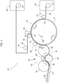
Figure 1 is a schematic view of a machine for producing single-dose capsules, -
Figure 2 is a schematic perspective view showing a water-soluble tape, -
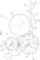
Figure 3 is a schematic view of a transverse cutting unit indicated by the arrow III inFigure 1 , -
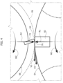
Figure 4 is a schematic view on an enlarged scale of the detail indicated by the arrow IV inFigure 3 , -
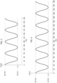
Figures 5 and 6 are graphs showing the variation of the peripheral speed of two embodiments of the knife roller during a complete rotation. - It will be appreciated that the accompanying drawings are schematic and that some components may not be for a better understanding of the figures. It will be appreciated that the various figures may also not be represented on the same scale.
- With reference to
Figure 1 , a machine for producing single-dose capsules is indicated by thereference number 10. - The
machine 10 comprises a formingsurface 12 having a plurality ofcavities 14, continuously movable in a machine direction MD. In the embodiment shown inFigure 1 , the formingsurface 12 is the outer cylindrical surface of awheel 16 rotating about a horizontal axis A. In a possible embodiment, the formingsurface 12 may be the outer surface of a closed-loop belt. - The
machine 10 comprises afirst feeding unit 18 configured to feed a first continuous water-soluble film 20 onto the formingsurface 12. The first continuous water-soluble film 20 is unwound from afirst reel 22 and is fed to the formingsurface 12 at afirst position 24. - The
machine 10 may comprise aheating device 25 arranged to heat the first continuous water-soluble film 20 upstream of the formingsurface 12. Theheating device 25 may comprise a heatedroller 27, which is in contact with the first continuous water-soluble film 20 upstream of thefirst position 24. - The first continuous water-
soluble film 20 is retained on the formingsurface 12 while moving in the machine direction MD. The first continuous water-soluble film 20 may be retained on the formingsurface 12 by mechanical retaining elements, which act on the lateral edges of the first continuous water-soluble film 20, for example, by belts which hold the lateral edges of the first continuous water-soluble film 20 on the outer surface of thewheel 16. - The first continuous water-
soluble film 20 deforms in thecavities 14 of the formingsurface 12 while moving in the machine direction MD. The deformation of the first continuous water-soluble film 20 at thecavities 14 may be obtained by a suction system comprising a plurality of holes opened on the surfaces of thecavities 14 and fluidly connected to a stationary suction chamber connected to a subatmospheric pressure source. The first continuous water-soluble film 20 is kept adherent to the walls of thecavities 14 by said suction system, so that a plurality of recesses are formed in the first continuous water-soluble film 20, having the same shape as thecavities 14. - The
machine 10 comprises asecond feeding unit 28 configured to feed a second continuous water-soluble film 30 onto the formingsurface 12 at asecond position 32 located downstream of thefirst position 24 with respect to the machine direction MD. The second continuous water-soluble film 30 is unwound from asecond reel 34. - The
machine 10 comprises adosing apparatus 36 configured to dispense metered quantities of at least one composition into the recesses of the first continuous water-soluble film 20, which are arranged at thecavities 14 of the formingsurface 12. Thedosing apparatus 36 is arranged in an intermediate position between thefirst position 24 and thesecond position 32. Thedosing apparatus 36 fills the recesses of the first continuous water-soluble film 20 with one or more compositions. After the recesses of the first continuous water-soluble film 20 have been filled with the compositions, the second continuous water-soluble film 30 is applied onto the first continuous water-soluble film 20, so as to enclose the metered amounts of compositions contained in the recesses between the first and the second continuous water-soluble film - The
machine 10 comprises awetting unit 38 configured to wet a surface of the second continuous water-soluble film 30 upstream of thesecond position 32. Thewetting unit 38 comprises awetting roller 39 that is in contact with the surface of the second continuous water-soluble film 30, which will be placed in contact with the first continuous water-soluble film 20. - The
machine 10 may comprise apressure roller 40 configured to press the first and second continuous water-soluble films surface 12 in the contact areas surrounding thecavities 14 containing the metered compositions. The first and second continuous water-soluble films - With reference to
Figure 2 , after the reciprocal bonding between the first and second continuous water-soluble films soluble tape 44 is formed. Within the water-soluble tape 44, single-dose capsules 46 are formed, connected and separated from each other byflat areas first side 21 and asecond side 31. - The single-
dose capsules 46 are arranged intransverse rows 48 andlongitudinal rows 50. The single-dose capsules 46 of thetransverse rows 48 are joined together by transverseflat areas 52, and the single-dose capsules 46 of thelongitudinal rows 50 are joined together by longitudinalflat areas 54. In theflat areas soluble films - The
flat areas - In a possible embodiment, the single-
dose capsules 46 protrude outwards from thefirst side 21, i.e. from the side of the first water-soluble film 20. - In a possible embodiment, the single-
dose capsules 46 protrude outwards from thesecond side 31, i.e. from the side of the second water-soluble film 30. - The
machine 10 comprises alongitudinal cutting unit 60 and atransverse cutting unit 62, which cut the water-soluble tape 44 along the longitudinalflat areas 54, and along the transverseflat areas 52, so as to form individual single-dose capsules 46. - In the embodiment illustrated in
Figure 1 , thelongitudinal cutting unit 60 is arranged upstream of thetransverse cutting unit 62 with reference to the machine direction MD. In this embodiment, thelongitudinal cutting unit 60 may comprise a plurality ofdiscs 61 cooperating with the formingsurface 12 and arranged to cut the water-soluble tape 44 along the longitudinalflat areas 54. - With reference to
Figures 1 and3 , thetransverse cutting unit 62 comprises ananvil 64 and aknife roller 66, rotating around respective rotation axes A and B, parallel to each other and perpendicular to the machine direction MD. The water-soluble tape 44 passes between theanvil 64 and theknife roller 66. Theknife roller 66 cuts the water-soluble tape 44 along the transverseflat areas 52. - With reference to
Figure 1 , themachine 10 may comprise aninlet transfer roller 68, which transfers the water-soluble tape 44 from the formingsurface 12 to theanvil 64, and anoutlet transfer roller 70, which receives the individual single-doses capsules 46 from theanvil 64 and transfers them to anoutlet conveyor 72. - In a possible embodiment (not shown) the
longitudinal cutting unit 60 may be arranged downstream of thetransverse cutting unit 62 with reference to the machine direction MD, so that the cutting of the transverseflat areas 52 is carried out before the cutting of the longitudinalflat areas 54. - With reference to
Figure 3 , theknife roller 66 comprises one ormore knives 74 mounted on therotating knife roller 66 and havingrespective cutting edges 76 movable along acircular path 78. The number ofknives 74 may vary from 1 to 10 according to the dimensions of theknife roller 66. Ifseveral knives 74 are provided, therespective cutting edges 76 are spaced apart from each other in an angular direction by an equal distance. - The
anvil 64 may have a plurality ofseats 80 configured to receive respective single-dose capsules 46. Theseats 80 may be configured to retain the single-dose capsules 46, for example, by suction. Theanvil 64 may have a plurality ofcontrast elements 82 that cooperate with the cutting edges 76 of theknives 74 to cut the transverseflat areas 52 of the water-soluble tape 44. Thecontrast elements 82 are arranged between two transverse rows ofseats 80 adjacent to each other. - The
anvil 64 and theknife roller 66 are driven in rotation around the respective rotation axes A and B by respectiveelectric motors 84, 86 controlled by a control unit 88. - With reference to
Figure 4 , the control unit 88 rotates theanvil 64 with a peripheral speed V1 equal to the feed rate of the water-soluble tape 44 in the machine direction MD. The peripheral speed V1 of theanvil 64 is the linear speed of theouter surfaces 84 of thecontrast elements 82, which is equal to the angular velocity W1 of theanvil 64 multiplied by the radial distance R1 between theouter surfaces 84 of thecontrast elements 82 and the rotation axis A of theanvil 64. - The control unit 88 rotates the
knife roller 66 with a variable peripheral speed V2 along thetrajectory 78. The peripheral speed V2 of theknife roller 66 is the linear speed of the cutting edges 76 of theknives 74, which is equal to the angular speed W2 of theknife roller 66 multiplied by the radial distance R2 between the cutting edges 76 of theknives 74 and the rotation axis B of theknife roller 66. - During a single cutting cycle, the
rotating knife roller 66 rotates with at least one first peripheral speed V2' and with a second peripheral speed V2". - The first peripheral speed V2' is greater than the peripheral speed V1 of the
anvil 64. The second peripheral speed V2" is at least 15% faster than the first peripheral speed V2'. - The
rotating knife roller 66 rotates at the speed V2' when eachindividual knife 74 cuts the water-soluble tape 44 in a direction transverse to the machine direction MD. - In one complete rotation of the
rotating knife roller 66, a number of cutting cycles equal to the number ofknives 74 on therotating knife roller 66 are performed. Each cut of the water-soluble tape 44 is carried out only one at a time by theknives 74. - In the instants wherein the
cutting edge 76 of aknife 74 comes into contact with arespective contrast element 82 of theanvil 64, the peripheral speed V2' of theknife roller 66 is greater than the peripheral speed V1 of theanvil 64. - In the instants wherein the
cutting edge 76 of aknife 74 comes into contact with arespective contrast element 82 of theanvil 64, the ratio V2'/V1 is between 1.1 and 1.25. In a possible embodiment, the speed ratio V2'/V1 is between 1.1 and 1.2. - It is advantageous that the speed ratio V2'/V1 does not drop to the value 1 because - in this way - it is not necessary to slow down the
knife roller 66 to the peripheral speed V1 and then accelerate it again. - It is also advantageous to avoid the speed ratio V2'/V1 from exceeding 1.25 to avoid risks of incomplete cuts, breakage of the capsules, snags in the line, and malformations of the cutting profile along the flat areas.
- In a possible embodiment, the ratio between the first peripheral speed V2' and the speed V1 is between 1.1 and 1.12. In this range, there are no incomplete cuts, broken capsules, snags in the line or malformations of the cutting profile along the flat areas. Compared to the wider range, in this case, the risks of malfunctions are absent, while with the wider range malfunctions are possible, although with a very low probability (about 2%).
- After having performed a cut, the peripheral speed V2 of the
knife roller 66 increases to the value V2" to align theknife 74, or asubsequent knife 74, with thesuccessive contrast element 82 in a subsequent cutting step. - The graphs of
Figures 5 and 6 show the variation of the ratio V2/V1 during a complete rotation of theknife roller 66.Figure 5 refers to aknife roller 66 having fourknives 74 andFigure 6 refers to aknife roller 66 having sixknives 74. The areas of the graphs wherein the V2/V1 ratio is minimum (equal to approximately 1.1) are the instants wherein the transverse cuts of the water-soluble tape 44 take place. - The difference between the peripheral speed V2' of the
cutting edge 76 of theknife roller 66 and the peripheral speed of theanvil 64 during the cutting of the water-soluble tape 44 causes the point of contact between the cuttingedge 76 and theanvil 64 to move between the instant of starting the cut and the instant of ending the cut. Since, during the cutting step, the peripheral speed V2' of theknife roller 66 is higher than the peripheral speed V1 of theanvil 64, theknife roller 66 disengages from theanvil 64 into a more advanced relative position than the relative position in which it was engaged. This relative displacement creates a detachment and a consequent spacing apart between the two cut edges of the first and second water-soluble films - The fact that during cutting a distance is formed between the cut edges of the water-
soluble films respective contrast elements 82. This leads to a consequent reduction in the stresses to which the cutting system is subjected (blades, shafts, bearings and motors). - The higher peripheral speed of the
knife roller 66 with respect to that of theanvil 64, other conditions being equal, also reduces the contact time between the cuttingedge 76 and theanvil 66. - Of course, without prejudice to the principle of the invention, the details of construction and the embodiments can be widely varied with respect to those described and illustrated, without thereby departing from the scope of the invention as defined by the claims that follow.
Claims (10)
- A method for cutting a water-soluble tape (44) comprising the steps of:- providing an anvil (64),- providing a rotating knife roller (66) comprising at least one knife (74) having a cutting edge (76) extending outwards from said rotating knife roller (66),- providing a water-soluble tape (44) comprising flat areas (52, 54) comprising a first side (21) and a second side (31), and single-dose capsules (46) formed inside the water-soluble tape (44), wherein the single-dose capsules (46) are connected and separated from each other by the flat areas (52, 54),- advancing said water-soluble tape (44) in a machine direction (MD) at a speed (V1) between said anvil (64) and said rotating knife roller (66) with said first side (21) of the water-soluble tape (44) in contact with the anvil (64),- cutting said water-soluble tape (44) with said at least one knife (74) while said water-soluble tape (44) passes between said anvil (64) and said rotating knife roller (66), wherein, during a single cutting cycle, the rotating knife roller (66) rotates with at least one first peripheral speed (V2') and a second peripheral speed (V2"), wherein the second peripheral speed (V2") is at least 15% faster than the first peripheral speed (V2') and wherein the rotating knife roller (66) rotates at the first peripheral speed (V2') when a knife (74) cuts said water-soluble tape (44) in a direction transverse to the machine direction (MD), wherein said method is characterized in that the ratio between the first peripheral speed (V2') and the speed (V1) is comprised between 1.1 and 1.25.
- The method of claim 1, wherein the ratio between the first peripheral speed (V2') and the speed (V1) is comprised between 1.1 and 1.12.
- The method of claim 1 or claim 2, wherein said rotating knife roller (66) comprises from one to ten knives (74).
- The method of any of the preceding claims, wherein said flat areas (52, 54) have a thickness of between 50 microns and 400 microns.
- The method of any of the preceding claims, wherein the single-dose capsules (46) project outwards from said first side (21).
- The method of any of claims 1-4, wherein the single-dose capsules (46) project outwards from said second side (31).
- The method of any of the preceding claims, comprising cutting the longitudinal flat areas (54) before cutting the transverse flat areas (52) of said water-soluble tape (44).
- The method of any of the preceding claims, wherein providing said water-soluble tape (44) comprises:- providing a forming surface (12) having a plurality of cavities (14), continuously movable in a machine direction (MD),- feeding a first continuous water-soluble film (20) onto said forming surface (12) in a first position (24),- retaining said first continuous water-soluble film (20) on said forming surface (12) while it moves in said machine direction (MD) and forming a plurality of recesses in said first continuous water-soluble film (20), while maintaining the first continuous water-soluble film (20) adherent to said cavities (14),- dispensing metered quantities of compositions into said recesses,- applying a second continuous water-soluble film (30) onto said first continuous water-soluble film (20) and connecting said first and second continuous water-soluble films (20, 22) together by water sealing around said recesses so as to enclose said metered quantities of compositions between said first and second continuous water-soluble films (20, 30).
- The method of any of the preceding claims, comprising receiving and holding said single-dose capsules (46) of said water-soluble tape (44) within the respective seats (80) of said anvil (64).
- The method of any one of the preceding claims, wherein each cut of the water-soluble tape (44) is carried out only one at a time of the knives (74).
Applications Claiming Priority (1)
| Application Number | Priority Date | Filing Date | Title |
|---|---|---|---|
| IT102022000013189A IT202200013189A1 (en) | 2022-06-22 | 2022-06-22 | Procedure for the transverse cutting of a water-soluble tape |
Publications (3)
| Publication Number | Publication Date |
|---|---|
| EP4296025A1 true EP4296025A1 (en) | 2023-12-27 |
| EP4296025B1 EP4296025B1 (en) | 2025-08-13 |
| EP4296025C0 EP4296025C0 (en) | 2025-08-13 |
Family
ID=83188909
Family Applications (1)
| Application Number | Title | Priority Date | Filing Date |
|---|---|---|---|
| EP23178466.1A Active EP4296025B1 (en) | 2022-06-22 | 2023-06-09 | A method for transverse cutting of a water-soluble tape |
Country Status (3)
| Country | Link |
|---|---|
| US (1) | US20230415367A1 (en) |
| EP (1) | EP4296025B1 (en) |
| IT (1) | IT202200013189A1 (en) |
Citations (5)
| Publication number | Priority date | Publication date | Assignee | Title |
|---|---|---|---|---|
| US20090321021A1 (en) * | 2008-06-30 | 2009-12-31 | Uni-Charm Corporation | Intermittent cutting transferring device |
| CN105438558A (en) * | 2015-12-15 | 2016-03-30 | 佛山市博维环保材料有限公司 | Continuous sealing structure of water-soluble film packaging machine |
| CN105539902A (en) * | 2016-02-16 | 2016-05-04 | 常州绿之源高分子材料有限公司 | Washing capsule production equipment adopting wet sealing method |
| US20170101204A1 (en) * | 2015-10-07 | 2017-04-13 | Cloud Packaging Solutions, LLC | System for Forming Packages From Film Material |
| US11124326B2 (en) | 2019-05-21 | 2021-09-21 | The Procter & Gamble Company | Process for cutting a water-soluble web |
Family Cites Families (8)
| Publication number | Priority date | Publication date | Assignee | Title |
|---|---|---|---|---|
| US3899945A (en) * | 1972-12-29 | 1975-08-19 | Koppers Co Inc | Method and apparatus for accurate die-cutting |
| US5151636A (en) * | 1990-03-12 | 1992-09-29 | Winebarger Kennith N | Rotary die cutting apparatus and method with disconnect |
| US6428001B1 (en) * | 2000-03-31 | 2002-08-06 | Heidelberger Druckmaschinen Ag | Signature slowdown apparatus |
| US7578501B2 (en) * | 2004-10-14 | 2009-08-25 | Muller Martini Mailroom Systems, Inc. | Product feeder with accelerator and decelerator devices |
| US8602957B2 (en) * | 2008-10-16 | 2013-12-10 | Goss International Americas, Inc. | Incremental velocity changing apparatus for transporting printed products in a printing press folder |
| US20100101386A1 (en) * | 2008-10-29 | 2010-04-29 | Goss International Americas, Inc. | Variable signature length web cutting apparatus |
| US9434083B2 (en) * | 2012-05-01 | 2016-09-06 | Goss International Americas, Inc. | Double cut folder with variable knife mounting locations on cutting cylinders |
| US20170173812A1 (en) * | 2015-12-16 | 2017-06-22 | Delta Industial Services, Inc. | Apparatus and method for rotary kiss cut liner efficiency |
-
2022
- 2022-06-22 IT IT102022000013189A patent/IT202200013189A1/en unknown
-
2023
- 2023-06-09 EP EP23178466.1A patent/EP4296025B1/en active Active
- 2023-06-21 US US18/338,445 patent/US20230415367A1/en active Pending
Patent Citations (5)
| Publication number | Priority date | Publication date | Assignee | Title |
|---|---|---|---|---|
| US20090321021A1 (en) * | 2008-06-30 | 2009-12-31 | Uni-Charm Corporation | Intermittent cutting transferring device |
| US20170101204A1 (en) * | 2015-10-07 | 2017-04-13 | Cloud Packaging Solutions, LLC | System for Forming Packages From Film Material |
| CN105438558A (en) * | 2015-12-15 | 2016-03-30 | 佛山市博维环保材料有限公司 | Continuous sealing structure of water-soluble film packaging machine |
| CN105539902A (en) * | 2016-02-16 | 2016-05-04 | 常州绿之源高分子材料有限公司 | Washing capsule production equipment adopting wet sealing method |
| US11124326B2 (en) | 2019-05-21 | 2021-09-21 | The Procter & Gamble Company | Process for cutting a water-soluble web |
Also Published As
| Publication number | Publication date |
|---|---|
| US20230415367A1 (en) | 2023-12-28 |
| IT202200013189A1 (en) | 2023-12-22 |
| EP4296025B1 (en) | 2025-08-13 |
| EP4296025C0 (en) | 2025-08-13 |
Similar Documents
| Publication | Publication Date | Title |
|---|---|---|
| EP3642007B1 (en) | Apparatus and process for forming water soluble pouches | |
| EP0061631B1 (en) | A device for packing sheet-like elements | |
| AU2004225982B2 (en) | High-speed continuous action form-fill-seal apparatus | |
| US4603540A (en) | Apparatus for making packaging bags | |
| PL161884B1 (en) | A device for the automatic production, filling and sealing of a specific number of compact packages PL PL PL PL | |
| CZ282954B6 (en) | Process for producing individually packed slices of a foodstuff article, and apparatus for making the same | |
| US4875329A (en) | Wrapping machine, particularly for blister packs and the like, with synchronized plural driving means | |
| EP4296025B1 (en) | A method for transverse cutting of a water-soluble tape | |
| JP2018524238A (en) | Package grouping unit with reduced package linear velocity | |
| EP3656534B1 (en) | A system for thermoformable film packaging of portioned products and a modular conveyor equipped with such a system | |
| EP3126119B1 (en) | Tight seal system for the packaging of products | |
| US7325386B2 (en) | Double action vertical form-fill-seal apparatus | |
| US20220332452A1 (en) | Dosing apparatus, and machine and method for producing unit dose articles | |
| US20210101704A1 (en) | Head for horizontal flow wrapper packaging machine | |
| CN112224478A (en) | A roller type water soluble film packaging machine | |
| CN217049298U (en) | Film feeding mechanism | |
| EP3663214A1 (en) | A film feeding system for a conveyor of a packaging machine, a conveyor and a machine equipped with such a system | |
| US11628956B2 (en) | Dosing unit, a dosing method, and a machine for producing unit dose articles | |
| CN213677292U (en) | Full-automatic water-soluble film packaging machine | |
| US11634245B2 (en) | Dosing unit, a dosing method, and a machine for producing unit dose articles | |
| CN112123435B (en) | Food multi-equal-division slitting and packaging equipment | |
| EP0104149A2 (en) | Device for forming, from the top downwards, articles into a stack of orderly layers | |
| ITTO960806A1 (en) | DEVICE TO APPLY TEAR BANDS | |
| CN102673012B (en) | Automatic on-line paper bag Breaching device | |
| CN109259934B (en) | System and method for manufacturing multi-connected bag sanitary products |
Legal Events
| Date | Code | Title | Description |
|---|---|---|---|
| PUAI | Public reference made under article 153(3) epc to a published international application that has entered the european phase |
Free format text: ORIGINAL CODE: 0009012 |
|
| STAA | Information on the status of an ep patent application or granted ep patent |
Free format text: STATUS: THE APPLICATION HAS BEEN PUBLISHED |
|
| AK | Designated contracting states |
Kind code of ref document: A1 Designated state(s): AL AT BE BG CH CY CZ DE DK EE ES FI FR GB GR HR HU IE IS IT LI LT LU LV MC ME MK MT NL NO PL PT RO RS SE SI SK SM TR |
|
| STAA | Information on the status of an ep patent application or granted ep patent |
Free format text: STATUS: REQUEST FOR EXAMINATION WAS MADE |
|
| 17P | Request for examination filed |
Effective date: 20240408 |
|
| RBV | Designated contracting states (corrected) |
Designated state(s): AL AT BE BG CH CY CZ DE DK EE ES FI FR GB GR HR HU IE IS IT LI LT LU LV MC ME MK MT NL NO PL PT RO RS SE SI SK SM TR |
|
| GRAP | Despatch of communication of intention to grant a patent |
Free format text: ORIGINAL CODE: EPIDOSNIGR1 |
|
| STAA | Information on the status of an ep patent application or granted ep patent |
Free format text: STATUS: GRANT OF PATENT IS INTENDED |
|
| INTG | Intention to grant announced |
Effective date: 20250409 |
|
| RIN1 | Information on inventor provided before grant (corrected) |
Inventor name: D'AURIZIO, MASSIMILIANO Inventor name: CENTORAME, OSCAR |
|
| GRAS | Grant fee paid |
Free format text: ORIGINAL CODE: EPIDOSNIGR3 |
|
| GRAA | (expected) grant |
Free format text: ORIGINAL CODE: 0009210 |
|
| STAA | Information on the status of an ep patent application or granted ep patent |
Free format text: STATUS: THE PATENT HAS BEEN GRANTED |
|
| AK | Designated contracting states |
Kind code of ref document: B1 Designated state(s): AL AT BE BG CH CY CZ DE DK EE ES FI FR GB GR HR HU IE IS IT LI LT LU LV MC ME MK MT NL NO PL PT RO RS SE SI SK SM TR |
|
| REG | Reference to a national code |
Ref country code: GB Ref legal event code: FG4D |
|
| REG | Reference to a national code |
Ref country code: CH Ref legal event code: EP |
|
| REG | Reference to a national code |
Ref country code: DE Ref legal event code: R096 Ref document number: 602023005626 Country of ref document: DE |
|
| REG | Reference to a national code |
Ref country code: IE Ref legal event code: FG4D |
|
| U01 | Request for unitary effect filed |
Effective date: 20250814 |
|
| U07 | Unitary effect registered |
Designated state(s): AT BE BG DE DK EE FI FR IT LT LU LV MT NL PT RO SE SI Effective date: 20250825 |
|
| PG25 | Lapsed in a contracting state [announced via postgrant information from national office to epo] |
Ref country code: IS Free format text: LAPSE BECAUSE OF FAILURE TO SUBMIT A TRANSLATION OF THE DESCRIPTION OR TO PAY THE FEE WITHIN THE PRESCRIBED TIME-LIMIT Effective date: 20251213 |
|
| PG25 | Lapsed in a contracting state [announced via postgrant information from national office to epo] |
Ref country code: NO Free format text: LAPSE BECAUSE OF FAILURE TO SUBMIT A TRANSLATION OF THE DESCRIPTION OR TO PAY THE FEE WITHIN THE PRESCRIBED TIME-LIMIT Effective date: 20251113 |
|
| PG25 | Lapsed in a contracting state [announced via postgrant information from national office to epo] |
Ref country code: HR Free format text: LAPSE BECAUSE OF FAILURE TO SUBMIT A TRANSLATION OF THE DESCRIPTION OR TO PAY THE FEE WITHIN THE PRESCRIBED TIME-LIMIT Effective date: 20250813 |
|
| PG25 | Lapsed in a contracting state [announced via postgrant information from national office to epo] |
Ref country code: GR Free format text: LAPSE BECAUSE OF FAILURE TO SUBMIT A TRANSLATION OF THE DESCRIPTION OR TO PAY THE FEE WITHIN THE PRESCRIBED TIME-LIMIT Effective date: 20251114 |
|
| PG25 | Lapsed in a contracting state [announced via postgrant information from national office to epo] |
Ref country code: PL Free format text: LAPSE BECAUSE OF FAILURE TO SUBMIT A TRANSLATION OF THE DESCRIPTION OR TO PAY THE FEE WITHIN THE PRESCRIBED TIME-LIMIT Effective date: 20250813 |
|
| PG25 | Lapsed in a contracting state [announced via postgrant information from national office to epo] |
Ref country code: RS Free format text: LAPSE BECAUSE OF FAILURE TO SUBMIT A TRANSLATION OF THE DESCRIPTION OR TO PAY THE FEE WITHIN THE PRESCRIBED TIME-LIMIT Effective date: 20251113 |
|
| PG25 | Lapsed in a contracting state [announced via postgrant information from national office to epo] |
Ref country code: ES Free format text: LAPSE BECAUSE OF FAILURE TO SUBMIT A TRANSLATION OF THE DESCRIPTION OR TO PAY THE FEE WITHIN THE PRESCRIBED TIME-LIMIT Effective date: 20250813 |
|
| PG25 | Lapsed in a contracting state [announced via postgrant information from national office to epo] |
Ref country code: SM Free format text: LAPSE BECAUSE OF FAILURE TO SUBMIT A TRANSLATION OF THE DESCRIPTION OR TO PAY THE FEE WITHIN THE PRESCRIBED TIME-LIMIT Effective date: 20250813 |
|
| PG25 | Lapsed in a contracting state [announced via postgrant information from national office to epo] |
Ref country code: CZ Free format text: LAPSE BECAUSE OF FAILURE TO SUBMIT A TRANSLATION OF THE DESCRIPTION OR TO PAY THE FEE WITHIN THE PRESCRIBED TIME-LIMIT Effective date: 20250813 |
|
| PG25 | Lapsed in a contracting state [announced via postgrant information from national office to epo] |
Ref country code: SK Free format text: LAPSE BECAUSE OF FAILURE TO SUBMIT A TRANSLATION OF THE DESCRIPTION OR TO PAY THE FEE WITHIN THE PRESCRIBED TIME-LIMIT Effective date: 20250813 |