EP4295981A1 - Draining mechanism - Google Patents
Draining mechanism Download PDFInfo
- Publication number
- EP4295981A1 EP4295981A1 EP22755960.6A EP22755960A EP4295981A1 EP 4295981 A1 EP4295981 A1 EP 4295981A1 EP 22755960 A EP22755960 A EP 22755960A EP 4295981 A1 EP4295981 A1 EP 4295981A1
- Authority
- EP
- European Patent Office
- Prior art keywords
- hole
- guide portion
- guide
- end portion
- wire electrode
- Prior art date
- Legal status (The legal status is an assumption and is not a legal conclusion. Google has not performed a legal analysis and makes no representation as to the accuracy of the status listed.)
- Pending
Links
- 230000005484 gravity Effects 0.000 claims abstract description 32
- 239000007788 liquid Substances 0.000 claims description 19
- 230000000149 penetrating effect Effects 0.000 claims description 4
- 239000012530 fluid Substances 0.000 description 58
- XLYOFNOQVPJJNP-UHFFFAOYSA-N water Substances O XLYOFNOQVPJJNP-UHFFFAOYSA-N 0.000 description 8
- 239000010802 sludge Substances 0.000 description 4
- 238000010586 diagram Methods 0.000 description 3
- 238000003754 machining Methods 0.000 description 3
- 239000007769 metal material Substances 0.000 description 3
- XEEYBQQBJWHFJM-UHFFFAOYSA-N Iron Chemical compound [Fe] XEEYBQQBJWHFJM-UHFFFAOYSA-N 0.000 description 2
- 238000001514 detection method Methods 0.000 description 2
- 239000000463 material Substances 0.000 description 2
- 229910001369 Brass Inorganic materials 0.000 description 1
- 229910000881 Cu alloy Inorganic materials 0.000 description 1
- 239000010951 brass Substances 0.000 description 1
- 238000001816 cooling Methods 0.000 description 1
- 239000008367 deionised water Substances 0.000 description 1
- 229910021641 deionized water Inorganic materials 0.000 description 1
- 229910052742 iron Inorganic materials 0.000 description 1
- 230000004048 modification Effects 0.000 description 1
- 238000012986 modification Methods 0.000 description 1
- WFKWXMTUELFFGS-UHFFFAOYSA-N tungsten Chemical compound [W] WFKWXMTUELFFGS-UHFFFAOYSA-N 0.000 description 1
- 229910052721 tungsten Inorganic materials 0.000 description 1
- 239000010937 tungsten Substances 0.000 description 1
Images


Classifications
-
- B—PERFORMING OPERATIONS; TRANSPORTING
- B23—MACHINE TOOLS; METAL-WORKING NOT OTHERWISE PROVIDED FOR
- B23H—WORKING OF METAL BY THE ACTION OF A HIGH CONCENTRATION OF ELECTRIC CURRENT ON A WORKPIECE USING AN ELECTRODE WHICH TAKES THE PLACE OF A TOOL; SUCH WORKING COMBINED WITH OTHER FORMS OF WORKING OF METAL
- B23H1/00—Electrical discharge machining, i.e. removing metal with a series of rapidly recurring electrical discharges between an electrode and a workpiece in the presence of a fluid dielectric
-
- B—PERFORMING OPERATIONS; TRANSPORTING
- B23—MACHINE TOOLS; METAL-WORKING NOT OTHERWISE PROVIDED FOR
- B23H—WORKING OF METAL BY THE ACTION OF A HIGH CONCENTRATION OF ELECTRIC CURRENT ON A WORKPIECE USING AN ELECTRODE WHICH TAKES THE PLACE OF A TOOL; SUCH WORKING COMBINED WITH OTHER FORMS OF WORKING OF METAL
- B23H1/00—Electrical discharge machining, i.e. removing metal with a series of rapidly recurring electrical discharges between an electrode and a workpiece in the presence of a fluid dielectric
- B23H1/10—Supply or regeneration of working media
-
- B—PERFORMING OPERATIONS; TRANSPORTING
- B23—MACHINE TOOLS; METAL-WORKING NOT OTHERWISE PROVIDED FOR
- B23H—WORKING OF METAL BY THE ACTION OF A HIGH CONCENTRATION OF ELECTRIC CURRENT ON A WORKPIECE USING AN ELECTRODE WHICH TAKES THE PLACE OF A TOOL; SUCH WORKING COMBINED WITH OTHER FORMS OF WORKING OF METAL
- B23H7/00—Processes or apparatus applicable to both electrical discharge machining and electrochemical machining
- B23H7/02—Wire-cutting
- B23H7/08—Wire electrodes
- B23H7/10—Supporting, winding or electrical connection of wire-electrode
-
- B—PERFORMING OPERATIONS; TRANSPORTING
- B23—MACHINE TOOLS; METAL-WORKING NOT OTHERWISE PROVIDED FOR
- B23H—WORKING OF METAL BY THE ACTION OF A HIGH CONCENTRATION OF ELECTRIC CURRENT ON A WORKPIECE USING AN ELECTRODE WHICH TAKES THE PLACE OF A TOOL; SUCH WORKING COMBINED WITH OTHER FORMS OF WORKING OF METAL
- B23H7/00—Processes or apparatus applicable to both electrical discharge machining and electrochemical machining
- B23H7/02—Wire-cutting
- B23H7/08—Wire electrodes
- B23H7/10—Supporting, winding or electrical connection of wire-electrode
- B23H7/101—Supply of working media
-
- B—PERFORMING OPERATIONS; TRANSPORTING
- B23—MACHINE TOOLS; METAL-WORKING NOT OTHERWISE PROVIDED FOR
- B23H—WORKING OF METAL BY THE ACTION OF A HIGH CONCENTRATION OF ELECTRIC CURRENT ON A WORKPIECE USING AN ELECTRODE WHICH TAKES THE PLACE OF A TOOL; SUCH WORKING COMBINED WITH OTHER FORMS OF WORKING OF METAL
- B23H7/00—Processes or apparatus applicable to both electrical discharge machining and electrochemical machining
- B23H7/02—Wire-cutting
- B23H7/08—Wire electrodes
- B23H7/10—Supporting, winding or electrical connection of wire-electrode
- B23H7/105—Wire guides
-
- B—PERFORMING OPERATIONS; TRANSPORTING
- B23—MACHINE TOOLS; METAL-WORKING NOT OTHERWISE PROVIDED FOR
- B23H—WORKING OF METAL BY THE ACTION OF A HIGH CONCENTRATION OF ELECTRIC CURRENT ON A WORKPIECE USING AN ELECTRODE WHICH TAKES THE PLACE OF A TOOL; SUCH WORKING COMBINED WITH OTHER FORMS OF WORKING OF METAL
- B23H7/00—Processes or apparatus applicable to both electrical discharge machining and electrochemical machining
- B23H7/02—Wire-cutting
- B23H7/08—Wire electrodes
- B23H7/10—Supporting, winding or electrical connection of wire-electrode
- B23H7/108—Used wire disposal devices
Definitions
- the present invention relates to a draining mechanism for removing, from a wire electrode, liquid flowing in a tube through which the wire electrode is inserted.
- JP H05-092322 A discloses a wire electric discharge machine provided with a guide pipe and a draining section.
- the guide pipe is a pipe for guiding water and a wire electrode.
- the draining section is provided at the discharge-side end of the guide pipe.
- the draining section is provided with a water suction section connected to an external suction device. The running water flowing through the guide pipe is sucked by the suction device from the water suction section of the draining section.
- a draining mechanism for removing liquid from a wire electrode, the liquid flowing in a tube through which a wire electrode is inserted and that guides feeding of the wire electrode includes:
- the dielectric working fluid can be removed from the wire electrode without a suction device. That is, in the embodiment of the present invention, the dielectric working fluid flowing out of the first guide portion is discharged under its own weight through the discharge hole. Further, the dielectric working fluid sticking to the wire electrode is blown off by the compressed gas introduced into the through hole between the first guide portion and the second guide portion. Thus, the dielectric working fluid can be removed from the wire electrode without a suction device.
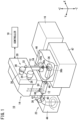
- FIG. 1 is a schematic diagram showing the configuration of a wire electric discharge machine 10 according to an embodiment.
- FIG. 1 shows an X direction, a Y direction, and a Z direction in which axes of the wire electric discharge machine 10 extends.
- the X direction and the Y direction are orthogonal to each other in a plane, and the Z direction is orthogonal to each of the X direction and the Y direction.
- the -Z direction is a direction in which gravity acts (gravity direction).
- the wire electric discharge machine 10 applies voltage between a to-be-processed object immersed in liquid and a wire electrode 12 (to a gap), thereby processing the object by electric discharge generated at the gap.
- the wire electric discharge machine 10 is provided with a machine main body 14, a dielectric fluid unit 16, and a controller 18 for controlling the machine main body 14 and the dielectric fluid unit 16.
- the wire electrode 12 is made of, for example, metal material such as tungsten-based, copper-alloy-based, or brass-based metal material.
- the object is made of, for example, metal material such as iron-based material or cemented carbide material.
- the machine main body 14 is provided with a supply system 20 for supplying a wire electrode 12 toward the object (workpiece), and a collection system 22 for collecting the wire electrode 12 that has passed through the object.
- the supply system 20 is provided with a wire bobbin 24, a torque motor 26, a brake shoe 28, a brake motor 30, a tension detection unit 32, and an upper die guide 34.
- An unused wire electrode 12 is wound around the wire bobbin 24.
- the torque motor 26 applies torque to the wire bobbin 24.
- the brake shoe 28 applies braking force of friction to the wire electrode 12.
- the brake motor 30 applies brake torque to the brake shoe 28.
- the tension detection unit 32 detects the magnitude of the tension on the wire electrode 12.
- the upper die guide 34 is a member for guiding the wire electrode 12 and is disposed above the object.
- the collection system 22 includes a lower die guide 36, a pinch roller 38 and a feed roller 40, a torque motor 42, and a collection box 44.
- the lower die guide 36 is a member for guiding the wire electrode 12 and is disposed below the object.
- the pinch roller 38 and the feed roller 40 sandwich and hold the wire electrode 12.
- the torque motor 42 applies torque to the feed roller 40.
- the collection box 44 collects the wire electrode 12 conveyed by the pinch roller 38 and the feed roller 40.
- the upper die guide 34 has a support portion 34a for supporting the wire electrode 12
- the lower die guide 36 has a support portion 36a for supporting the wire electrode 12.
- the lower die guide 36 includes a guide roller 36b for changing the direction of the wire electrode 12 and guiding the wire electrode 12 to the pinch roller 38 and the feed roller 40.
- the upper die guide 34 jets clean dielectric working fluid free from sludge (machining chips) toward the gap between the wire electrode 12 and the object.
- the gap can be filled with a clean liquid suitable for processing, and it can be prevented that sludge created in accordance with the processing lowers the processing accuracy.
- the lower die guide 36 may jet clean dielectric working fluid free from sludge (machining chips) toward the gap between the wire electrode 12 and the object.
- the machine main body 14 is provided with a work-pan 46 capable of storing dielectric working fluid.
- the dielectric working fluid is liquid used at the time of machining.
- deionized water and suchlike can be raised.
- the work-pan 46 is mounted on the base 47.
- the upper die guide 34 and a lower die guide 36 are arranged in a work-pan 46, and an object is provided between the upper die guide 34 and the lower die guide 36.
- the upper die guide 34, the lower die guide 36, and the object are immersed in the dielectric working fluid stored in the work-pan 46.
- a tube 48 for guiding the delivery of the wire electrode 12 is attached to a side wall of the work-pan 46.
- the tube 48 communicates with the work-pan 46.
- the wire electrode 12 fed through the guide roller 36b is inserted into the tube 48, and the dielectric working fluid in the work-pan 46 flows into the tube 48.
- the wire electrode 12 inserted into the tube 48 is fed toward a discharge-side end portion of the tube 48.
- the dielectric working fluid flowing into the tube 48 flows toward the discharge-side end portion of the tube 48.
- a draining mechanism 50 is provided at the discharge-side end portion of the tube 48. The draining mechanism 50 removes, from the wire electrode 12, the dielectric working fluid flowing through the tube 48.
- the wire electrode 12 fed from the draining mechanism 50 is collected into the collection box 44 via the pinch roller 38 and the feed roller 40.
- the dielectric fluid unit 16 removes sludge generated in the work-pan 46. Further, the dielectric fluid unit 16 controls the liquid quality of the dielectric working fluid by adjusting the electrical resistivity, the temperature, and suchlike. The dielectric working fluid whose liquid quality has been controlled by the dielectric fluid unit 16 is returned to the work-pan 46 and ejected from at least the upper die guide 34.
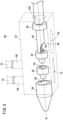
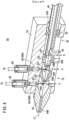
- FIG. 2 is a cross-sectional view showing the configuration of the draining mechanism 50 according to the embodiment.
- FIG. 3 is a view showing a draining mechanism 50 according to the embodiment focusing on the inside of the draining mechanism 50.
- the draining mechanism 50 includes a block 52, a first guide portion 54, a second guide portion 56, and a third guide portion 58.
- the block 52 is a base member of the water draining mechanism 50.
- the block 52 is fixed, for example, to a housing wall of the machine main body 14 (see FIG. 1 ).
- the block 52 is formed with a through hole 52H penetrating therethrough along a direction intersecting the gravity direction. In the case of the present embodiment, the through hole 52H penetrates in a direction orthogonal to the gravity direction (-Z direction).
- One end portion of the through hole 52H is an end portion on the side where the wire electrode 12 is inserted, and the other end portion of the through hole 52H is an end portion on the side where the wire electrode 12 is drawn out.
- one end of the through hole 52H is referred to as an input end portion, and the other end of the through hole 52H is referred to as an output end portion.
- a discharge side end portion of the tube 48 is disposed at the input end portion of the through hole 52H.
- the discharge-side end portion of the tube 48 is fixed to the block 52 with a fixing member 59.
- a virtual center line of the discharge side end portion of the tube 48 fixed to the block 52 substantially coincides with a virtual center line VL of the through hole 52H.
- the virtual center line VL is an imaginary line passing through the center of the cross section of the through hole 52H.
- the imaginary center line of the tube 48 is an imaginary line passing through the center of the cross section of the tube 48.
- the discharge-side end portion of the tube 48 is provided with a cut 60 for removing the dielectric working fluid that flows out of the discharge-side end portion of the tube 48.
- the cut 60 is provided in the gravity direction (-Z direction). By providing the cut 60, the inside of the discharge side end portion of the tube 48 is exposed to the through hole 52H of the block 52.
- the block 52 is provided with a drain channel 62 for guiding the dielectric working fluid that flows out of the cut 60 to the outside of the block 52 in the gravity direction (-Z direction).
- the drain channel 62 extends in the gravity direction and passes through the cut 60 and the outside of the block 52.
- the first guide portion 54 is provided between the discharge side end portion of the tube 48 and the output end portion side of the through hole 52H.
- the first guide portion 54 is formed with a guide hole 64 for guiding the wire electrode 12 from the input end portion side to the output end portion side of the through hole 52H.
- the guide hole 64 has a tapered portion 64A and an extended portion 64B. An imaginary center line passing through the center of the cross section of the guide hole 64 substantially coincides with the imaginary center line VL of the through hole 52H.
- the tapered portion 64A is formed in such a way that the hole becomes smaller from the input end portion side to the output end portion side of the through hole 52H.
- the tapered portion 64A guides the tip of the wire electrode 12 to the extended portion 64B.
- the extended portion 64B extends to the output end portion side of the through hole 52H with the size of the extended portion 64B being approximately the same as the size of the hole at the tip of the tapered portion 64A.
- the extended portion 64B is formed in the direction in which the through hole 52H penetrates. The extended portion 64B guides the feeding of the wire electrode 12 while maintaining the position of the wire electrode 12 substantially unchanged.
- the second guide portion 56 is provided at an output end portion of the through hole 52H.
- the second guide portion 56 is separated from the first guide portion 54. Part of the second guide portion 56 may extend from the output end portion of the through hole 52H to the outside of the block 52.
- the second guide portion 56 is formed with a guide hole 64.
- the extended portion 64B of the guide hole 64 in the second guide portion 56 may be longer than the extended portion 64B of the guide hole 64 in the first guide portion 54.
- the second guide portion 56 can stably guide the feeding of the wire electrode 12 in comparison with when the extended portion 64B of the second guide portion 56 is the same as the extended portion 64B of the first guide portion 54.
- the third guide portion 58 is provided in the through hole 52H between the first guide portion 54 and the second guide portion 56.
- the third guide portion 58 is separated from the first guide portion 54 and the second guide portion 56.
- the third guide portion 58 is formed with a guide hole 64.
- An outlet of a gas channel 66 of the block 52 opens on the through hole 52H between the third guide portion 58 and the first guide portion 54.
- an outlet of a gas channel 66 of the block 52 opens on the through hole 52H between the third guide portion 58 and the second guide portion 56.
- the gas channel 66 may be constituted by two channels having independent inlets for each of the two outlets or may be constituted by one channel having a common inlet for the two outlets.
- the gas channel 66 is constituted by two channels. One of the two channels constituting the gas channel 66 is referred to as a first gas channel 66A, and the other of the two channels constituting the gas channel 66 is referred to as a second gas channel 66B.
- the first gas channel 66A has the outlet connected to the through hole 52H between the third guide portion 58 and the first guide portion 54, and the inlet connected to the outside of the block 52.
- the second gas channel 66B has the outlet connected to the through hole 52H at a position between the third guide portion 58 and the second guide portion 56, and the inlet connected to the outside of the block 52.
- a joint member 68 is provided at each inlet of the first gas channel 66A and the second gas channel 66B.
- the joint member 68 connects the gas channel 66 (the first gas channel 66A or the second gas channel 66B) and a gas tube 70.
- One end of the gas tube 70 is attached to the joint member 68, and the other end of the gas tube 70 is attached to a compressor.
- the compressor may be one dedicated to the draining mechanism 50 or may be one not dedicated to the water draining mechanism 50.
- the compressor not dedicated to the draining mechanism 50 can be raised a compressor that supplies compressed gas for cooling the wire electrode 12 when the wire electrode 12 is cut.
- a compressor may be used that supplies a compressed gas for driving a cylinder bubble that controls the flow of dielectric working fluid for feeding the wire electrode 12.
- the outlets of the first gas channel 66A and the second gas channel 66B are arranged, in the direction (+Z direction) opposite to the gravity direction (-Z direction), from the path of the wire electrode 12 guided from the input end portion side to the output end portion side of the through hole 52H.
- the outlets of the first gas channel 66A and the second gas channel 66B open toward the path of the wire electrode 12.
- An inlet of a discharge hole 72 of the block 52 opens on the through hole 52H between the third guide portion 58 and the first guide portion 54 and between the third guide portion 58 and the second guide portion 56.
- the discharge hole 72 may be constituted by two passages having independent outlets for each of the two inlets or may be constituted by one passage having a common outlet for the two inlets, or may be constituted by one passage having a common inlet and outlet.
- the discharge hole 72 is constituted by one passage having a common inlet and outlet.
- the discharge hole 72 extends in the gravity direction.
- the inlet of the discharge hole 72 is connected to the through hole 52H from between the third guide portion 58 and the first guide portion 54 to between the third guide portion 58 and the second guide portion 56.
- the outlet of the discharge hole 72 is connected to the outside of the block 52.
- FIG. 4 is a view showing a state of flow of the dielectric working fluid in the draining mechanism 50.
- the wire electrode 12 fed from the discharge side end portion of the tube 48 is guided sequentially to the first guide portion 54, the third guide portion 58, and the second guide portion 56.
- the wire electrode 12 guided by the second guide portion 56 is fed out of the draining mechanism 50.
- the compressed gas supplied from the compressor to the draining mechanism 50 via the gas tube 70 is blown, via the first gas channel 66A, onto the wire electrode 12 fed from the first guide portion 54 to the third guide portion 58.
- the compressed gas supplied from the compressor to the draining mechanism 50 via the gas tube 70 is blown, via the second gas channel 66B, onto the wire electrode 12 fed from the third guide portion 58 to the second guide portion 56.
- Specific examples of the gas used for the compressed gas include air and suchlike.
- the dielectric working fluid scattered in the guide hole 64 of the first guide portion 54 moves on an inner wall surface of the first guide portion 54, which inclines so as to become lower from the output end portion side to the input end portion side of the through hole 52H, and falls down via the drain channel 62.
- the dielectric working fluid flowing out from the first guide portion 54 to the output end portion side of the through hole 52H falls under its own weight through the discharge hole 72.
- the dielectric working fluid adhering to the wire electrode 12 is scattered by the compressed gas blown thereon through the gas channel 66.
- the scattered dielectric working fluid sticks to an inner wall surface of the block 52, an inner wall surface of the third guide portion 58, or an inner wall surface of the second guide portion 56.
- the inner wall surface of the third guide portion 58 or the inner wall surface of the second guide portion 56 inclines so as to become lower from the output end portion side to the input end portion side of the through hole 52H.
- the dielectric working fluid sticking to the inner wall surface moves on the inner wall surface under its own weight and falls via the discharge hole 72.
- the block 52 of the draining mechanism 50 includes the gas channels 66 for guiding the compressed gas to part of the through hole 52H between the first guide portion 54 and the second guide portion 56. Further, the block 52 includes the discharge hole 72 connected to the through hole 52H at a position between the first guide portion 54 and the second guide portion 56, extending in the gravity direction and being connected to the outside of the block 52.
- the draining mechanism 50 can drain, via the discharge hole 72, the dielectric working fluid flowing from the first guide portion 54 to a space between the first guide portion 54 and the second guide portion 56, using the weight of the dielectric working fluid itself. Further, using by the compressed gas guided to the through hole 52H, the draining mechanism 50 can blow away the dielectric working fluid sticking to the wire electrode 12 that passes through the through hole 52H. As a result, according to the draining mechanism 50, the dielectric working fluid can be removed from the wire electrode 12 without a suction device.
- the outlets of the gas channels 66 are arranged, in the direction opposite to the gravity direction, from the path of the wire electrode 12 guided from the input end portion side to the output end portion side of the through hole 52H.
- the compressed gas can be blown onto the wire electrode 12, whereby the dielectric working fluid sticking to the wire electrode 12 can be guided to the discharge hole 72. Therefore, the dielectric working fluid can be removed more efficiently than in a case where the outlets of the gas channel 66 would not be arranged from the path of the wire electrode 12 in the direction opposite to the gravity direction.
- the cut 60 is provided at the gravity-direction wall portion of the discharge-side end portion of the tube 48.
- the block 52 of the draining mechanism 50 is formed with the drain channel 62 that guides the dielectric working fluid flowing out of the cut 60 to the outside of the block 52 in the gravity direction.
- the draining mechanism 50 can discharge, via the drain channel 62, most of the dielectric working fluid flowing in the tube 48.
- the draining mechanism 50 can shorten the length of the block 52 in the direction in which the through hole 52H penetrates.
- the draining mechanism 50 can discharge, to the outside of the block 52, most of the dielectric working fluid flowing out of the discharge-side end portion of the tube 48 without guiding it into the first guide portion 54.
- the third guide portion 58 is provided in the through hole 52H between the first guide portion 54 and the second guide portion 56, apart from the first guide portion 54 and from the second guide portion 56.
- the gas channels 66 of the draining mechanism 50 are connected to the through hole 52H at positions between the first guide portion 54 and the third guide portion 58 and between the second guide portion 56 and the third guide portion 58.
- the guide hole 64 has the tapered portion 64A.
- the tapered portion 64A is formed in such a way that the hole becomes smaller from the input end portion side to the output end portion side of the through hole 52H.
- the inner wall surfaces of the guide portions (the first guide portion 54, the second guide portion 56 and the third guide portion 58) inclines so as to become lower from the output end portion side to the input end portion side of the through hole 52H. Therefore, the dielectric working fluid scattered on the tapered portion 64A can be discharged via the drain channel 62 or the discharge hole 72.
- FIG. 5 is a cross-sectional view showing a configuration of a draining mechanism 50 according to the first modified example.
- components equivalent to those described above are denoted by the same reference numerals.
- descriptions that overlap with those described above are omitted.
- the outlet of at least one of the first gas channel 66A and the second gas channel 66B is not limited to the case where it is arranged from the path of the wire electrode 12 in the direction opposite to the gravity direction.
- the outlet of at least one of the first gas channel 66A and the second gas channel 66B may be arranged on an inner wall surface of the block 52 that is positioned from the path of the wire electrode 12 in the gravity direction.
- the outlet of at least one of the first gas channel 66A and the second gas channel 66B may be arranged on an inner wall surface of the block 52 that intersects a plane passing through the path of the wire electrode 12 in the X direction.
- the first gas channel 66A may have two or more outlets connected to the through hole 52H at positions between the first guide portion 54 and the third guide portion 58. Further, the second gas channel 66B may have two or more outlets connected to the through hole 52H at positions between the second guide portion 56 and the third guide portion 58. In these cases, in comparison with the case where the first gas channel 66A or the second gas channel 66B has only one outlet, more dielectric working fluid can be blown off the wire electrode 12.
- the third guide portion 58 may be omitted. Further, two or more third guide portions 58 may be provided in the through hole 52H between the first guide portion 54 and the second guide portion 56. When two or more third guide portions 58 are provided, an interval is provided between adjacent third guide portions 58.
- the gas channel 66 has an outlet connected to the through hole 52H between adjacent third guide portions 58. When two or more third guide portions 58 are provided, more dielectric working fluid can be removed from the wire electrode 12 than a case where only one third guide portion 58 is provided.
- the present invention is the draining mechanism (50) for removing liquid from a wire electrode, the liquid flowing in a tube (48) into which the wire electrode (12) is inserted and that guides feeding of the wire electrode, the draining mechanism (50) comprising: a block (52) that is formed with a through hole (52H) penetrating in a direction intersecting a gravity direction, wherein a discharge-side end portion of the tube is disposed at one end portion of the through hole; a first guide portion (54) that is provided between the discharge-side end portion of the tube and another end portion of the through hole and is formed with a guide hole (64) guiding the wire electrode from one end side of the through hole to another end side of the through hole; and, a second guide portion (56) that is provided at another end portion of the through hole so as to be apart from the first guide portion and is formed with the guide hole, and wherein the block includes: a gas channel (66) that is connected to the through hole between the first guide portion and the second guide portion and guides, to the through hole, compressed
- the dielectric working fluid flowing from the first guide portion to the output end portion side of the through hole can be discharged through the discharge hole under its own weight, and the dielectric working fluid sticking to the wire electrode can be blown off by the compressed gas guided to the through hole. As a result, the dielectric working fluid can be removed from the wire electrode without a suction device.
- the outlet of the gas channel may be arranged in a direction opposite to the gravity direction from a path of the wire electrode guided from the one end portion side of the through hole to the another end portion side of the through hole.
- the compressed gas can be blown onto the wire electrode and the dielectric working fluid sticking to the wire electrode can be guided to the discharge hole. Therefore, the dielectric working fluid can be removed more efficiently than in a case where the outlet of the gas channel would not be arranged from the path of the wire electrode in the direction opposite to the gravity direction.
- a wall portion of the discharge-side end portion of the tube in the gravity direction may be provided with a cut (60) that drains the liquid, and the block may include a drain channel (62) that guides, to the outside of the block in the gravity direction, the liquid flowing out from the cut.
- the first guide portion may be provided so as to be apart from the discharge side end portion of the tube, and the block may include a drain channel that guides the liquid flowing out from the discharge-side end portion of the tube to the outside of the block in the gravity direction. Thus, most of the dielectric working fluid flowing in the tube can be discharged through the drain channel.
- the draining mechanism may further include a third guide portion (58) that is provided in the through hole between the first guide portion and the second guide portion so as to be apart from the first guide portion and the second guide portion and is formed with the guide hole, wherein the gas channel may be one of a plurality of gas channels, and the plurality of gas channels are connected to the through hole at a position between the first guide portion and the third guide portion and a position between the second guide portion and the third guide portion.
- the amount of dielectric working fluid to be removed from the wire electrode can be increased in comparison with the case where the third guide portion is not provided.
- the guide hole may include a tapered portion (64A) formed so as to become smaller toward the one end portion of the through hole.
- the inner wall surface of the guide portion inclines so as to become lower from the output end portion side to the input end portion side of the through hole. Therefore, the dielectric working fluid scattered on the tapered portion can be discharged through the drain channel or the discharge hole.
Landscapes
- Engineering & Computer Science (AREA)
- Mechanical Engineering (AREA)
- Chemical & Material Sciences (AREA)
- Chemical Kinetics & Catalysis (AREA)
- Electrochemistry (AREA)
- Electrical Discharge Machining, Electrochemical Machining, And Combined Machining (AREA)
- Toys (AREA)
- Sampling And Sample Adjustment (AREA)
- X-Ray Techniques (AREA)
Abstract
Description
- The present invention relates to a draining mechanism for removing, from a wire electrode, liquid flowing in a tube through which the wire electrode is inserted.
-
JP H05-092322 A - However, there is a need for a draining mechanism for removing liquid flowing inside the tube from the wire electrode without using a suction device.
- Accordingly, it is an object of the present invention to solve the above-described problems.
- According to an aspect of the present invention,
a draining mechanism for removing liquid from a wire electrode, the liquid flowing in a tube through which a wire electrode is inserted and that guides feeding of the wire electrode, the draining mechanism includes: - a block that is formed with a through hole penetrating in a direction intersecting a gravity direction, wherein a discharge-side end portion of the tube is disposed at one end portion of the through hole;
- a first guide portion that is provided between the discharge-side end portion of the tube and another end portion of the through hole and is formed with a guide hole guiding the wire electrode from one end portion side of the through hole to another end portion side of the through hole;
- a second guide portion that is provided at another end portion of the through hole so as to be apart from the first guide portion and is formed with the guide hole; and
- wherein
- the block includes:
- a gas channel that is connected to the through hole between the first guide portion and the second guide portion and guides to the through hole compressed gas supplied from the outside; and
- a discharge hole that is connected to the through hole at a position between the first guide portion and the second guide portion, and extends in the gravity direction and is connected to the outside of the block.
- According to the aspect of the present invention, the dielectric working fluid can be removed from the wire electrode without a suction device. That is, in the embodiment of the present invention, the dielectric working fluid flowing out of the first guide portion is discharged under its own weight through the discharge hole. Further, the dielectric working fluid sticking to the wire electrode is blown off by the compressed gas introduced into the through hole between the first guide portion and the second guide portion. Thus, the dielectric working fluid can be removed from the wire electrode without a suction device.
-
-
FIG. 1 is a schematic diagram showing a configuration of a wire electric discharge machine according to an embodiment; -
FIG. 2 is a cross-sectional view showing a configuration of a draining mechanism according to an embodiment; -
FIG. 3 is a diagram showing the draining mechanism according to the embodiment focusing on the inside of the draining mechanism; -
FIG. 4 is a view showing the flow of dielectric working fluid in the draining mechanism; and -
FIG. 5 is a cross-sectional view showing a configuration of a draining mechanism according to a first modification. -
FIG. 1 is a schematic diagram showing the configuration of a wireelectric discharge machine 10 according to an embodiment.FIG. 1 shows an X direction, a Y direction, and a Z direction in which axes of the wireelectric discharge machine 10 extends. The X direction and the Y direction are orthogonal to each other in a plane, and the Z direction is orthogonal to each of the X direction and the Y direction. Note that the -Z direction is a direction in which gravity acts (gravity direction). - The wire
electric discharge machine 10 applies voltage between a to-be-processed object immersed in liquid and a wire electrode 12 (to a gap), thereby processing the object by electric discharge generated at the gap. The wireelectric discharge machine 10 is provided with a machinemain body 14, adielectric fluid unit 16, and acontroller 18 for controlling the machinemain body 14 and thedielectric fluid unit 16. - The
wire electrode 12 is made of, for example, metal material such as tungsten-based, copper-alloy-based, or brass-based metal material. On the other hand, the object is made of, for example, metal material such as iron-based material or cemented carbide material. - The machine
main body 14 is provided with asupply system 20 for supplying awire electrode 12 toward the object (workpiece), and acollection system 22 for collecting thewire electrode 12 that has passed through the object. - The
supply system 20 is provided with awire bobbin 24, atorque motor 26, abrake shoe 28, abrake motor 30, atension detection unit 32, and anupper die guide 34. Anunused wire electrode 12 is wound around thewire bobbin 24. Thetorque motor 26 applies torque to thewire bobbin 24. Thebrake shoe 28 applies braking force of friction to thewire electrode 12. Thebrake motor 30 applies brake torque to thebrake shoe 28. Thetension detection unit 32 detects the magnitude of the tension on thewire electrode 12. Theupper die guide 34 is a member for guiding thewire electrode 12 and is disposed above the object. - The
collection system 22 includes alower die guide 36, apinch roller 38 and afeed roller 40, atorque motor 42, and acollection box 44. Thelower die guide 36 is a member for guiding thewire electrode 12 and is disposed below the object. Thepinch roller 38 and thefeed roller 40 sandwich and hold thewire electrode 12. Thetorque motor 42 applies torque to thefeed roller 40. Thecollection box 44 collects thewire electrode 12 conveyed by thepinch roller 38 and thefeed roller 40. - The
upper die guide 34 has asupport portion 34a for supporting thewire electrode 12, and thelower die guide 36 has asupport portion 36a for supporting thewire electrode 12. Thelower die guide 36 includes aguide roller 36b for changing the direction of thewire electrode 12 and guiding thewire electrode 12 to thepinch roller 38 and thefeed roller 40. - The
upper die guide 34 jets clean dielectric working fluid free from sludge (machining chips) toward the gap between thewire electrode 12 and the object. As a result, the gap can be filled with a clean liquid suitable for processing, and it can be prevented that sludge created in accordance with the processing lowers the processing accuracy. As theupper die guide 34, thelower die guide 36 may jet clean dielectric working fluid free from sludge (machining chips) toward the gap between thewire electrode 12 and the object. - The machine
main body 14 is provided with a work-pan 46 capable of storing dielectric working fluid. The dielectric working fluid is liquid used at the time of machining. As examples of the dielectric working fluid, deionized water and suchlike can be raised. The work-pan 46 is mounted on thebase 47. - The
upper die guide 34 and alower die guide 36 are arranged in a work-pan 46, and an object is provided between theupper die guide 34 and thelower die guide 36. Theupper die guide 34, thelower die guide 36, and the object are immersed in the dielectric working fluid stored in the work-pan 46. - A
tube 48 for guiding the delivery of thewire electrode 12 is attached to a side wall of the work-pan 46. Thetube 48 communicates with the work-pan 46. Thewire electrode 12 fed through theguide roller 36b is inserted into thetube 48, and the dielectric working fluid in the work-pan 46 flows into thetube 48. Thewire electrode 12 inserted into thetube 48 is fed toward a discharge-side end portion of thetube 48. The dielectric working fluid flowing into thetube 48 flows toward the discharge-side end portion of thetube 48. Adraining mechanism 50 is provided at the discharge-side end portion of thetube 48. Thedraining mechanism 50 removes, from thewire electrode 12, the dielectric working fluid flowing through thetube 48. Thewire electrode 12 fed from thedraining mechanism 50 is collected into thecollection box 44 via thepinch roller 38 and thefeed roller 40. - The
dielectric fluid unit 16 removes sludge generated in the work-pan 46. Further, thedielectric fluid unit 16 controls the liquid quality of the dielectric working fluid by adjusting the electrical resistivity, the temperature, and suchlike. The dielectric working fluid whose liquid quality has been controlled by thedielectric fluid unit 16 is returned to the work-pan 46 and ejected from at least theupper die guide 34. -
FIG. 2 is a cross-sectional view showing the configuration of thedraining mechanism 50 according to the embodiment.FIG. 3 is a view showing adraining mechanism 50 according to the embodiment focusing on the inside of thedraining mechanism 50. Thedraining mechanism 50 includes ablock 52, afirst guide portion 54, asecond guide portion 56, and athird guide portion 58. - The
block 52 is a base member of thewater draining mechanism 50. Theblock 52 is fixed, for example, to a housing wall of the machine main body 14 (seeFIG. 1 ). Theblock 52 is formed with a throughhole 52H penetrating therethrough along a direction intersecting the gravity direction. In the case of the present embodiment, the throughhole 52H penetrates in a direction orthogonal to the gravity direction (-Z direction). - One end portion of the through
hole 52H is an end portion on the side where thewire electrode 12 is inserted, and the other end portion of the throughhole 52H is an end portion on the side where thewire electrode 12 is drawn out. Hereinafter, one end of the throughhole 52H is referred to as an input end portion, and the other end of the throughhole 52H is referred to as an output end portion. - A discharge side end portion of the
tube 48 is disposed at the input end portion of the throughhole 52H. The discharge-side end portion of thetube 48 is fixed to theblock 52 with a fixingmember 59. A virtual center line of the discharge side end portion of thetube 48 fixed to theblock 52 substantially coincides with a virtual center line VL of the throughhole 52H. The virtual center line VL is an imaginary line passing through the center of the cross section of the throughhole 52H. The imaginary center line of thetube 48 is an imaginary line passing through the center of the cross section of thetube 48. - The discharge-side end portion of the
tube 48 is provided with acut 60 for removing the dielectric working fluid that flows out of the discharge-side end portion of thetube 48. Thecut 60 is provided in the gravity direction (-Z direction). By providing thecut 60, the inside of the discharge side end portion of thetube 48 is exposed to the throughhole 52H of theblock 52. - The
block 52 is provided with adrain channel 62 for guiding the dielectric working fluid that flows out of thecut 60 to the outside of theblock 52 in the gravity direction (-Z direction). Thedrain channel 62 extends in the gravity direction and passes through thecut 60 and the outside of theblock 52. - The
first guide portion 54 is provided between the discharge side end portion of thetube 48 and the output end portion side of the throughhole 52H. Thefirst guide portion 54 is formed with aguide hole 64 for guiding thewire electrode 12 from the input end portion side to the output end portion side of the throughhole 52H. Theguide hole 64 has a taperedportion 64A and anextended portion 64B. An imaginary center line passing through the center of the cross section of theguide hole 64 substantially coincides with the imaginary center line VL of the throughhole 52H. - The tapered
portion 64A is formed in such a way that the hole becomes smaller from the input end portion side to the output end portion side of the throughhole 52H. The taperedportion 64A guides the tip of thewire electrode 12 to theextended portion 64B. Theextended portion 64B extends to the output end portion side of the throughhole 52H with the size of theextended portion 64B being approximately the same as the size of the hole at the tip of the taperedportion 64A. Theextended portion 64B is formed in the direction in which the throughhole 52H penetrates. Theextended portion 64B guides the feeding of thewire electrode 12 while maintaining the position of thewire electrode 12 substantially unchanged. - The
second guide portion 56 is provided at an output end portion of the throughhole 52H. Thesecond guide portion 56 is separated from thefirst guide portion 54. Part of thesecond guide portion 56 may extend from the output end portion of the throughhole 52H to the outside of theblock 52. Thesecond guide portion 56 is formed with aguide hole 64. - The
extended portion 64B of theguide hole 64 in thesecond guide portion 56 may be longer than theextended portion 64B of theguide hole 64 in thefirst guide portion 54. When theextended portion 64B of thesecond guide portion 56 is longer than theextended portion 64B of thefirst guide portion 54, thesecond guide portion 56 can stably guide the feeding of thewire electrode 12 in comparison with when theextended portion 64B of thesecond guide portion 56 is the same as theextended portion 64B of thefirst guide portion 54. - The
third guide portion 58 is provided in the throughhole 52H between thefirst guide portion 54 and thesecond guide portion 56. Thethird guide portion 58 is separated from thefirst guide portion 54 and thesecond guide portion 56. Thethird guide portion 58 is formed with aguide hole 64. - An outlet of a
gas channel 66 of theblock 52 opens on the throughhole 52H between thethird guide portion 58 and thefirst guide portion 54. In addition, an outlet of agas channel 66 of theblock 52 opens on the throughhole 52H between thethird guide portion 58 and thesecond guide portion 56. Thegas channel 66 may be constituted by two channels having independent inlets for each of the two outlets or may be constituted by one channel having a common inlet for the two outlets. In the present embodiment, thegas channel 66 is constituted by two channels. One of the two channels constituting thegas channel 66 is referred to as afirst gas channel 66A, and the other of the two channels constituting thegas channel 66 is referred to as asecond gas channel 66B. - The
first gas channel 66A has the outlet connected to the throughhole 52H between thethird guide portion 58 and thefirst guide portion 54, and the inlet connected to the outside of theblock 52. Thesecond gas channel 66B has the outlet connected to the throughhole 52H at a position between thethird guide portion 58 and thesecond guide portion 56, and the inlet connected to the outside of theblock 52. - A
joint member 68 is provided at each inlet of thefirst gas channel 66A and thesecond gas channel 66B. Thejoint member 68 connects the gas channel 66 (thefirst gas channel 66A or thesecond gas channel 66B) and agas tube 70. One end of thegas tube 70 is attached to thejoint member 68, and the other end of thegas tube 70 is attached to a compressor. The compressor may be one dedicated to thedraining mechanism 50 or may be one not dedicated to thewater draining mechanism 50. As an example of the compressor not dedicated to thedraining mechanism 50, can be raised a compressor that supplies compressed gas for cooling thewire electrode 12 when thewire electrode 12 is cut. Further, for example, a compressor may be used that supplies a compressed gas for driving a cylinder bubble that controls the flow of dielectric working fluid for feeding thewire electrode 12. - The outlets of the
first gas channel 66A and thesecond gas channel 66B are arranged, in the direction (+Z direction) opposite to the gravity direction (-Z direction), from the path of thewire electrode 12 guided from the input end portion side to the output end portion side of the throughhole 52H. The outlets of thefirst gas channel 66A and thesecond gas channel 66B open toward the path of thewire electrode 12. - An inlet of a
discharge hole 72 of theblock 52 opens on the throughhole 52H between thethird guide portion 58 and thefirst guide portion 54 and between thethird guide portion 58 and thesecond guide portion 56. Thedischarge hole 72 may be constituted by two passages having independent outlets for each of the two inlets or may be constituted by one passage having a common outlet for the two inlets, or may be constituted by one passage having a common inlet and outlet. In the present embodiment, thedischarge hole 72 is constituted by one passage having a common inlet and outlet. - The
discharge hole 72 extends in the gravity direction. The inlet of thedischarge hole 72 is connected to the throughhole 52H from between thethird guide portion 58 and thefirst guide portion 54 to between thethird guide portion 58 and thesecond guide portion 56. The outlet of thedischarge hole 72 is connected to the outside of theblock 52. -
FIG. 4 is a view showing a state of flow of the dielectric working fluid in thedraining mechanism 50. Thewire electrode 12 fed from the discharge side end portion of thetube 48 is guided sequentially to thefirst guide portion 54, thethird guide portion 58, and thesecond guide portion 56. Thewire electrode 12 guided by thesecond guide portion 56 is fed out of thedraining mechanism 50. - On the other hand, the compressed gas supplied from the compressor to the
draining mechanism 50 via thegas tube 70 is blown, via thefirst gas channel 66A, onto thewire electrode 12 fed from thefirst guide portion 54 to thethird guide portion 58. The compressed gas supplied from the compressor to thedraining mechanism 50 via thegas tube 70 is blown, via thesecond gas channel 66B, onto thewire electrode 12 fed from thethird guide portion 58 to thesecond guide portion 56. Specific examples of the gas used for the compressed gas include air and suchlike. - On the other hand, most of the dielectric working fluid flowing in the
tube 48 falls, via thedrain channel 62, from thecut 60 provided at the discharge-side end portion of thetube 48. A small portion of the dielectric working fluid flowing in thetube 48 is scattered to theguide hole 64 of thefirst guide portion 54. Alternatively, a small portion of the dielectric working fluid flowing in thetube 48 flows out from thefirst guide portion 54 to the output end portion side of the throughhole 52H. Alternatively, a small portion of the dielectric working fluid flowing in thetube 48 sticks to thewire electrode 12. - The dielectric working fluid scattered in the
guide hole 64 of thefirst guide portion 54 moves on an inner wall surface of thefirst guide portion 54, which inclines so as to become lower from the output end portion side to the input end portion side of the throughhole 52H, and falls down via thedrain channel 62. - The dielectric working fluid flowing out from the
first guide portion 54 to the output end portion side of the throughhole 52H falls under its own weight through thedischarge hole 72. - The dielectric working fluid adhering to the
wire electrode 12 is scattered by the compressed gas blown thereon through thegas channel 66. The scattered dielectric working fluid sticks to an inner wall surface of theblock 52, an inner wall surface of thethird guide portion 58, or an inner wall surface of thesecond guide portion 56. The inner wall surface of thethird guide portion 58 or the inner wall surface of thesecond guide portion 56 inclines so as to become lower from the output end portion side to the input end portion side of the throughhole 52H. The dielectric working fluid sticking to the inner wall surface moves on the inner wall surface under its own weight and falls via thedischarge hole 72. - As described above, the
block 52 of thedraining mechanism 50 according to the present embodiment includes thegas channels 66 for guiding the compressed gas to part of the throughhole 52H between thefirst guide portion 54 and thesecond guide portion 56. Further, theblock 52 includes thedischarge hole 72 connected to the throughhole 52H at a position between thefirst guide portion 54 and thesecond guide portion 56, extending in the gravity direction and being connected to the outside of theblock 52. - Thus, the
draining mechanism 50 according to the present embodiment can drain, via thedischarge hole 72, the dielectric working fluid flowing from thefirst guide portion 54 to a space between thefirst guide portion 54 and thesecond guide portion 56, using the weight of the dielectric working fluid itself. Further, using by the compressed gas guided to the throughhole 52H, thedraining mechanism 50 can blow away the dielectric working fluid sticking to thewire electrode 12 that passes through the throughhole 52H. As a result, according to thedraining mechanism 50, the dielectric working fluid can be removed from thewire electrode 12 without a suction device. - In the present embodiment, the outlets of the
gas channels 66 are arranged, in the direction opposite to the gravity direction, from the path of thewire electrode 12 guided from the input end portion side to the output end portion side of the throughhole 52H. As a result, the compressed gas can be blown onto thewire electrode 12, whereby the dielectric working fluid sticking to thewire electrode 12 can be guided to thedischarge hole 72. Therefore, the dielectric working fluid can be removed more efficiently than in a case where the outlets of thegas channel 66 would not be arranged from the path of thewire electrode 12 in the direction opposite to the gravity direction. - Further, in the present embodiment, the
cut 60 is provided at the gravity-direction wall portion of the discharge-side end portion of thetube 48. Theblock 52 of thedraining mechanism 50 is formed with thedrain channel 62 that guides the dielectric working fluid flowing out of thecut 60 to the outside of theblock 52 in the gravity direction. Thus, even when thetube 48 is brought into contact with thefirst guide portion 54, thedraining mechanism 50 can discharge, via thedrain channel 62, most of the dielectric working fluid flowing in thetube 48. As a result, thedraining mechanism 50 can shorten the length of theblock 52 in the direction in which the throughhole 52H penetrates. Further, thedraining mechanism 50 can discharge, to the outside of theblock 52, most of the dielectric working fluid flowing out of the discharge-side end portion of thetube 48 without guiding it into thefirst guide portion 54. - In addition, in the present embodiment, the
third guide portion 58 is provided in the throughhole 52H between thefirst guide portion 54 and thesecond guide portion 56, apart from thefirst guide portion 54 and from thesecond guide portion 56. In addition, thegas channels 66 of thedraining mechanism 50 are connected to the throughhole 52H at positions between thefirst guide portion 54 and thethird guide portion 58 and between thesecond guide portion 56 and thethird guide portion 58. As a result, the certainty of removing the dielectric working fluid from thewire electrode 12 can be enhanced as compared with a case where thethird guide portion 58 would not be provided. - Further, in this embodiment, the
guide hole 64 has the taperedportion 64A. The taperedportion 64A is formed in such a way that the hole becomes smaller from the input end portion side to the output end portion side of the throughhole 52H. Thus, the inner wall surfaces of the guide portions (thefirst guide portion 54, thesecond guide portion 56 and the third guide portion 58) inclines so as to become lower from the output end portion side to the input end portion side of the throughhole 52H. Therefore, the dielectric working fluid scattered on the taperedportion 64A can be discharged via thedrain channel 62 or thedischarge hole 72. - The above-described embodiment may be modified as follows.
-
FIG. 5 is a cross-sectional view showing a configuration of adraining mechanism 50 according to the first modified example. InFIG. 5 , components equivalent to those described above are denoted by the same reference numerals. In this modified example, descriptions that overlap with those described above are omitted. - In this modified example, there is no cut 60 (
FIG. 2 ) at the discharge-side end portion of thetube 48, and thefirst guide portion 54 is provided at a distance from the discharge-side end portion of thetube 48. Thus, as in the above-described embodiment, most of the dielectric working fluid flowing in thetube 48 can be discharged via thewater drain channel 62. - The outlet of at least one of the
first gas channel 66A and thesecond gas channel 66B is not limited to the case where it is arranged from the path of thewire electrode 12 in the direction opposite to the gravity direction. For example, the outlet of at least one of thefirst gas channel 66A and thesecond gas channel 66B may be arranged on an inner wall surface of theblock 52 that is positioned from the path of thewire electrode 12 in the gravity direction. Alternatively, the outlet of at least one of thefirst gas channel 66A and thesecond gas channel 66B may be arranged on an inner wall surface of theblock 52 that intersects a plane passing through the path of thewire electrode 12 in the X direction. - The
first gas channel 66A may have two or more outlets connected to the throughhole 52H at positions between thefirst guide portion 54 and thethird guide portion 58. Further, thesecond gas channel 66B may have two or more outlets connected to the throughhole 52H at positions between thesecond guide portion 56 and thethird guide portion 58. In these cases, in comparison with the case where thefirst gas channel 66A or thesecond gas channel 66B has only one outlet, more dielectric working fluid can be blown off thewire electrode 12. - The
third guide portion 58 may be omitted. Further, two or morethird guide portions 58 may be provided in the throughhole 52H between thefirst guide portion 54 and thesecond guide portion 56. When two or morethird guide portions 58 are provided, an interval is provided between adjacentthird guide portions 58. Thegas channel 66 has an outlet connected to the throughhole 52H between adjacentthird guide portions 58. When two or morethird guide portions 58 are provided, more dielectric working fluid can be removed from thewire electrode 12 than a case where only onethird guide portion 58 is provided. - Hereinafter, the invention that can be understood from the above-described embodiments and modified examples will be described.
- The present invention is the draining mechanism (50) for removing liquid from a wire electrode, the liquid flowing in a tube (48) into which the wire electrode (12) is inserted and that guides feeding of the wire electrode, the draining mechanism (50) comprising: a block (52) that is formed with a through hole (52H) penetrating in a direction intersecting a gravity direction, wherein a discharge-side end portion of the tube is disposed at one end portion of the through hole; a first guide portion (54) that is provided between the discharge-side end portion of the tube and another end portion of the through hole and is formed with a guide hole (64) guiding the wire electrode from one end side of the through hole to another end side of the through hole; and, a second guide portion (56) that is provided at another end portion of the through hole so as to be apart from the first guide portion and is formed with the guide hole, and wherein the block includes: a gas channel (66) that is connected to the through hole between the first guide portion and the second guide portion and guides, to the through hole, compressed gas supplied from an outside; and, a discharge hole (72) that is connected to the through hole at a position between the first guide portion and the second guide portion, and extends in the gravity direction and is connected to the outside of the block.
- Thus, the dielectric working fluid flowing from the first guide portion to the output end portion side of the through hole can be discharged through the discharge hole under its own weight, and the dielectric working fluid sticking to the wire electrode can be blown off by the compressed gas guided to the through hole. As a result, the dielectric working fluid can be removed from the wire electrode without a suction device.
- The outlet of the gas channel may be arranged in a direction opposite to the gravity direction from a path of the wire electrode guided from the one end portion side of the through hole to the another end portion side of the through hole. As a result, the compressed gas can be blown onto the wire electrode and the dielectric working fluid sticking to the wire electrode can be guided to the discharge hole. Therefore, the dielectric working fluid can be removed more efficiently than in a case where the outlet of the gas channel would not be arranged from the path of the wire electrode in the direction opposite to the gravity direction.
- A wall portion of the discharge-side end portion of the tube in the gravity direction may be provided with a cut (60) that drains the liquid, and the block may include a drain channel (62) that guides, to the outside of the block in the gravity direction, the liquid flowing out from the cut. Thus, even if the tube is brought into contact with the first guide portion, most of the dielectric working fluid flowing in the tube can be discharged through the drain channel. As a result, the length of the block in the direction in which the through hole penetrates can be reduced. Further, most of the dielectric working fluid flowing out from the discharge-side end portion of the tube can be discharged to the outside of the block without flowing into the first guide portion.
- The first guide portion may be provided so as to be apart from the discharge side end portion of the tube, and the block may include a drain channel that guides the liquid flowing out from the discharge-side end portion of the tube to the outside of the block in the gravity direction. Thus, most of the dielectric working fluid flowing in the tube can be discharged through the drain channel.
- The draining mechanism may further include a third guide portion (58) that is provided in the through hole between the first guide portion and the second guide portion so as to be apart from the first guide portion and the second guide portion and is formed with the guide hole, wherein the gas channel may be one of a plurality of gas channels, and the plurality of gas channels are connected to the through hole at a position between the first guide portion and the third guide portion and a position between the second guide portion and the third guide portion. As a result, the amount of dielectric working fluid to be removed from the wire electrode can be increased in comparison with the case where the third guide portion is not provided.
- The guide hole may include a tapered portion (64A) formed so as to become smaller toward the one end portion of the through hole. Thus, the inner wall surface of the guide portion inclines so as to become lower from the output end portion side to the input end portion side of the through hole. Therefore, the dielectric working fluid scattered on the tapered portion can be discharged through the drain channel or the discharge hole.
Claims (6)
- A draining mechanism (50) for removing liquid from a wire electrode, the liquid flowing in a tube (48) into which the wire electrode (12) is inserted and that guides feeding of the wire electrode, the draining mechanism (50) comprising:a block (52) that is formed with a through hole (52H) penetrating in a direction intersecting a gravity direction, wherein a discharge-side end portion of the tube is disposed at one end portion of the through hole;a first guide portion (54) that is provided between the discharge-side end portion of the tube and another end portion of the through hole and is formed with a guide hole (64) guiding the wire electrode from one end portion side of the through hole to another end portion side of the through hole; anda second guide portion (56) that is provided at the another end portion of the through hole so as to be apart from the first guide portion, and is formed with the guide hole,whereinthe block includes:a gas channel (66) that is connected to the through hole at a position between the first guide portion and the second guide portion and guides, to the through hole, compressed gas supplied from an outside; anda discharge hole (72) that is connected to the through hole at a position between the first guide portion and the second guide portion, and extends in the gravity direction and is connected to an outside of the block.
- The draining mechanism according to claim 1, wherein
an outlet of the gas channel is arranged in a direction opposite to the gravity direction from a path of the wire electrode guided from the one end portion side of the through hole to the another end portion side of the through hole. - The draining mechanism according to claim 1 or 2, whereina wall portion of the discharge-side end portion of the tube in the gravity direction is provided with a cut (60) that drains the liquid, andthe block includes a drain channel (62) that guides, to the outside of the block in the gravity direction, the liquid flowing out from the cut.
- The draining mechanism according to claim 1 or 2, whereinthe first guide portion is provided so as to be apart from the discharge side end portion of the tube, andthe block includes a drain channel that guides, to the outside of the block in the gravity direction, the liquid flowing out from the discharge-side end portion of the tube.
- The draining mechanism according to any one of claims 1 to 4,further comprising a third guide portion (58) that is provided in the through hole between the first guide portion and the second guide portion so as to be apart from the first guide portion and the second guide portion and is formed with the guide hole,whereinthe gas channel is one of a plurality of gas channels,the plurality of gas channels are connected to the through hole at a position between the first guide portion and the third guide portion and a position between the second guide portion and the third guide portion.
- The draining mechanism according to any one of claims 1 to 5, wherein
the guide hole includes a tapered portion (64A) that is formed so as to become smaller toward the one end portion of the through hole.
Applications Claiming Priority (2)
| Application Number | Priority Date | Filing Date | Title |
|---|---|---|---|
| JP2021023102 | 2021-02-17 | ||
| PCT/JP2022/004350 WO2022176639A1 (en) | 2021-02-17 | 2022-02-04 | Draining mechanism |
Publications (2)
| Publication Number | Publication Date |
|---|---|
| EP4295981A1 true EP4295981A1 (en) | 2023-12-27 |
| EP4295981A4 EP4295981A4 (en) | 2025-02-19 |
Family
ID=82932063
Family Applications (1)
| Application Number | Title | Priority Date | Filing Date |
|---|---|---|---|
| EP22755960.6A Pending EP4295981A4 (en) | 2021-02-17 | 2022-02-04 | EMPTYING DEVICE |
Country Status (7)
| Country | Link |
|---|---|
| US (1) | US20240123529A1 (en) |
| EP (1) | EP4295981A4 (en) |
| JP (1) | JP7513830B2 (en) |
| KR (1) | KR20230145350A (en) |
| CN (1) | CN116829288A (en) |
| TW (1) | TWI907647B (en) |
| WO (1) | WO2022176639A1 (en) |
Family Cites Families (8)
| Publication number | Priority date | Publication date | Assignee | Title |
|---|---|---|---|---|
| JPS6399132A (en) * | 1986-10-15 | 1988-04-30 | Fanuc Ltd | Draining device of wire cut electric discharge machine |
| JP3243570B2 (en) | 1991-09-30 | 2002-01-07 | 株式会社 アマダマシニックス | Wire electrode transfer device of wire electric discharge machine |
| JPH10180546A (en) * | 1996-12-24 | 1998-07-07 | Hitachi Cable Ltd | Method of manufacturing electrode wire for electric discharge machining |
| JP3541807B2 (en) * | 1997-12-22 | 2004-07-14 | 三菱電機株式会社 | Wire electric discharge machine |
| WO1999061191A1 (en) * | 1998-05-28 | 1999-12-02 | Mitsubishi Denki Kabushiki Kaisha | Wire electric discharge machine |
| JP4331119B2 (en) * | 2005-02-16 | 2009-09-16 | 西部電機株式会社 | Wire electrical discharge machine |
| KR20110024331A (en) * | 2009-09-02 | 2011-03-09 | 두산인프라코어 주식회사 | Wire discharge device of wire discharge machine |
| JP5622981B1 (en) * | 2014-02-20 | 2014-11-12 | 三菱電機株式会社 | Wire electrical discharge machine |
-
2022
- 2022-02-04 KR KR1020237027111A patent/KR20230145350A/en active Pending
- 2022-02-04 EP EP22755960.6A patent/EP4295981A4/en active Pending
- 2022-02-04 CN CN202280014326.2A patent/CN116829288A/en active Pending
- 2022-02-04 WO PCT/JP2022/004350 patent/WO2022176639A1/en not_active Ceased
- 2022-02-04 US US18/277,514 patent/US20240123529A1/en active Pending
- 2022-02-04 JP JP2023500714A patent/JP7513830B2/en active Active
- 2022-02-15 TW TW111105348A patent/TWI907647B/en active
Also Published As
| Publication number | Publication date |
|---|---|
| TWI907647B (en) | 2025-12-11 |
| KR20230145350A (en) | 2023-10-17 |
| EP4295981A4 (en) | 2025-02-19 |
| JPWO2022176639A1 (en) | 2022-08-25 |
| US20240123529A1 (en) | 2024-04-18 |
| CN116829288A (en) | 2023-09-29 |
| JP7513830B2 (en) | 2024-07-09 |
| TW202235189A (en) | 2022-09-16 |
| WO2022176639A1 (en) | 2022-08-25 |
Similar Documents
| Publication | Publication Date | Title |
|---|---|---|
| JP3097793B2 (en) | Wire cutting machine with wire guiding device for electric discharge machine | |
| CN106029275B (en) | Wire electric discharge machine | |
| EP0142034A1 (en) | Traveling-wire electroerosion machines with double-floating nozzle assemblies | |
| US20240123529A1 (en) | Draining mechanism | |
| JP4331119B2 (en) | Wire electrical discharge machine | |
| JPS62130129A (en) | Wire electrode set device for wire cut electric discharge machining | |
| JP5225516B1 (en) | Wire electrode feeder and wire electric discharge machine | |
| JP3563690B2 (en) | Apparatus and method for introducing machining electrode of electric discharge machine | |
| CN1137010C (en) | Wire cut electric discharge machining device | |
| CN109834348B (en) | Wire electric discharge machining apparatus | |
| JP3623363B2 (en) | Wire feeding device in wire electric discharge machine | |
| JPS62188627A (en) | Wire electric discharge machine | |
| JP2000296416A (en) | Wire feeder in wire electric discharge machine | |
| JP3922974B2 (en) | Automatic wire feeder for wire electric discharge machine | |
| JPH09262721A (en) | Wire feeder for wire electric discharge machine | |
| JP2005125413A (en) | Device for collecting cut piece of wire electrode | |
| JPS6214374B2 (en) | ||
| JPH10151527A (en) | Wire direction changing device of electrical discharge machine | |
| JPH0248122A (en) | Wire electric spark machine | |
| JP3968578B2 (en) | Wire electrode guide device in wire electric discharge machine | |
| EP4368327A1 (en) | Wire electric discharge machining apparatus | |
| JP3572133B2 (en) | Wire feeder for immersion type wire electric discharge machine | |
| JPH01321126A (en) | Wiring device for wire type electric discharge machine | |
| CN115666837B (en) | Wire electrode recovery device and wire electric discharge machining device | |
| TWI676514B (en) | Automatic elimination device for waste line electrodes |
Legal Events
| Date | Code | Title | Description |
|---|---|---|---|
| STAA | Information on the status of an ep patent application or granted ep patent |
Free format text: STATUS: THE INTERNATIONAL PUBLICATION HAS BEEN MADE |
|
| PUAI | Public reference made under article 153(3) epc to a published international application that has entered the european phase |
Free format text: ORIGINAL CODE: 0009012 |
|
| STAA | Information on the status of an ep patent application or granted ep patent |
Free format text: STATUS: REQUEST FOR EXAMINATION WAS MADE |
|
| 17P | Request for examination filed |
Effective date: 20230810 |
|
| AK | Designated contracting states |
Kind code of ref document: A1 Designated state(s): AL AT BE BG CH CY CZ DE DK EE ES FI FR GB GR HR HU IE IS IT LI LT LU LV MC MK MT NL NO PL PT RO RS SE SI SK SM TR |
|
| DAV | Request for validation of the european patent (deleted) | ||
| DAX | Request for extension of the european patent (deleted) | ||
| A4 | Supplementary search report drawn up and despatched |
Effective date: 20250122 |
|
| RIC1 | Information provided on ipc code assigned before grant |
Ipc: B23H 1/10 20060101ALI20250116BHEP Ipc: B23H 7/10 20060101AFI20250116BHEP |