EP4295878A2 - Electronic aerosol provision system and method - Google Patents
Electronic aerosol provision system and method Download PDFInfo
- Publication number
- EP4295878A2 EP4295878A2 EP23196391.9A EP23196391A EP4295878A2 EP 4295878 A2 EP4295878 A2 EP 4295878A2 EP 23196391 A EP23196391 A EP 23196391A EP 4295878 A2 EP4295878 A2 EP 4295878A2
- Authority
- EP
- European Patent Office
- Prior art keywords
- inhalation
- airflow
- aerosol
- user
- phase
- Prior art date
- Legal status (The legal status is an assumption and is not a legal conclusion. Google has not performed a legal analysis and makes no representation as to the accuracy of the status listed.)
- Pending
Links
- 239000000443 aerosol Substances 0.000 title claims abstract description 179
- 238000000034 method Methods 0.000 title claims abstract description 44
- 238000005259 measurement Methods 0.000 claims description 21
- 238000004891 communication Methods 0.000 claims description 2
- 238000001514 detection method Methods 0.000 abstract description 18
- 230000004044 response Effects 0.000 abstract description 13
- 239000003571 electronic cigarette Substances 0.000 description 33
- 239000000463 material Substances 0.000 description 27
- 239000002245 particle Substances 0.000 description 27
- 239000007788 liquid Substances 0.000 description 16
- SNICXCGAKADSCV-JTQLQIEISA-N (-)-Nicotine Chemical compound CN1CCC[C@H]1C1=CC=CN=C1 SNICXCGAKADSCV-JTQLQIEISA-N 0.000 description 13
- 229960002715 nicotine Drugs 0.000 description 13
- SNICXCGAKADSCV-UHFFFAOYSA-N nicotine Natural products CN1CCCC1C1=CC=CN=C1 SNICXCGAKADSCV-UHFFFAOYSA-N 0.000 description 13
- 230000004913 activation Effects 0.000 description 12
- 238000001994 activation Methods 0.000 description 12
- 238000010586 diagram Methods 0.000 description 11
- 238000010438 heat treatment Methods 0.000 description 9
- 239000004480 active ingredient Substances 0.000 description 8
- 239000000796 flavoring agent Substances 0.000 description 8
- 235000019634 flavors Nutrition 0.000 description 8
- 210000004072 lung Anatomy 0.000 description 8
- 230000000694 effects Effects 0.000 description 7
- 241000208125 Nicotiana Species 0.000 description 6
- 235000002637 Nicotiana tabacum Nutrition 0.000 description 6
- 239000000203 mixture Substances 0.000 description 6
- PEDCQBHIVMGVHV-UHFFFAOYSA-N Glycerine Chemical compound OCC(O)CO PEDCQBHIVMGVHV-UHFFFAOYSA-N 0.000 description 5
- 230000008859 change Effects 0.000 description 5
- 239000000470 constituent Substances 0.000 description 5
- 230000003213 activating effect Effects 0.000 description 4
- 239000011149 active material Substances 0.000 description 4
- 239000000499 gel Substances 0.000 description 4
- 239000004615 ingredient Substances 0.000 description 4
- 238000010295 mobile communication Methods 0.000 description 4
- 238000003860 storage Methods 0.000 description 4
- 238000009834 vaporization Methods 0.000 description 4
- DNIAPMSPPWPWGF-UHFFFAOYSA-N Propylene glycol Chemical compound CC(O)CO DNIAPMSPPWPWGF-UHFFFAOYSA-N 0.000 description 3
- 230000006399 behavior Effects 0.000 description 3
- MTHSVFCYNBDYFN-UHFFFAOYSA-N diethylene glycol Chemical compound OCCOCCO MTHSVFCYNBDYFN-UHFFFAOYSA-N 0.000 description 3
- 239000007787 solid Substances 0.000 description 3
- 230000007704 transition Effects 0.000 description 3
- PUPZLCDOIYMWBV-UHFFFAOYSA-N (+/-)-1,3-Butanediol Chemical compound CC(O)CCO PUPZLCDOIYMWBV-UHFFFAOYSA-N 0.000 description 2
- VZWGRQBCURJOMT-UHFFFAOYSA-N Dodecyl acetate Chemical compound CCCCCCCCCCCCOC(C)=O VZWGRQBCURJOMT-UHFFFAOYSA-N 0.000 description 2
- MWAYRGBWOVHDDZ-UHFFFAOYSA-N Ethyl vanillate Chemical compound CCOC(=O)C1=CC=C(O)C(OC)=C1 MWAYRGBWOVHDDZ-UHFFFAOYSA-N 0.000 description 2
- UYXTWWCETRIEDR-UHFFFAOYSA-N Tributyrin Chemical compound CCCC(=O)OCC(OC(=O)CCC)COC(=O)CCC UYXTWWCETRIEDR-UHFFFAOYSA-N 0.000 description 2
- 238000013459 approach Methods 0.000 description 2
- SESFRYSPDFLNCH-UHFFFAOYSA-N benzyl benzoate Chemical compound C=1C=CC=CC=1C(=O)OCC1=CC=CC=C1 SESFRYSPDFLNCH-UHFFFAOYSA-N 0.000 description 2
- -1 botanical matter Substances 0.000 description 2
- 238000004590 computer program Methods 0.000 description 2
- 239000004020 conductor Substances 0.000 description 2
- 230000008094 contradictory effect Effects 0.000 description 2
- 238000013500 data storage Methods 0.000 description 2
- POULHZVOKOAJMA-UHFFFAOYSA-N dodecanoic acid Chemical compound CCCCCCCCCCCC(O)=O POULHZVOKOAJMA-UHFFFAOYSA-N 0.000 description 2
- MMXKVMNBHPAILY-UHFFFAOYSA-N ethyl laurate Chemical compound CCCCCCCCCCCC(=O)OCC MMXKVMNBHPAILY-UHFFFAOYSA-N 0.000 description 2
- 239000006260 foam Substances 0.000 description 2
- 238000009472 formulation Methods 0.000 description 2
- 235000011187 glycerol Nutrition 0.000 description 2
- 238000005304 joining Methods 0.000 description 2
- 238000004519 manufacturing process Methods 0.000 description 2
- 239000008204 material by function Substances 0.000 description 2
- 230000007246 mechanism Effects 0.000 description 2
- 239000007769 metal material Substances 0.000 description 2
- 230000004048 modification Effects 0.000 description 2
- 238000012986 modification Methods 0.000 description 2
- 239000004033 plastic Substances 0.000 description 2
- 230000001007 puffing effect Effects 0.000 description 2
- 230000000717 retained effect Effects 0.000 description 2
- 238000007493 shaping process Methods 0.000 description 2
- 230000008685 targeting Effects 0.000 description 2
- 238000012549 training Methods 0.000 description 2
- URAYPUMNDPQOKB-UHFFFAOYSA-N triacetin Chemical compound CC(=O)OCC(OC(C)=O)COC(C)=O URAYPUMNDPQOKB-UHFFFAOYSA-N 0.000 description 2
- 229940058015 1,3-butylene glycol Drugs 0.000 description 1
- OKTJSMMVPCPJKN-UHFFFAOYSA-N Carbon Chemical compound [C] OKTJSMMVPCPJKN-UHFFFAOYSA-N 0.000 description 1
- 229920000742 Cotton Polymers 0.000 description 1
- 239000004348 Glyceryl diacetate Substances 0.000 description 1
- 239000005639 Lauric acid Substances 0.000 description 1
- MIYFJEKZLFWKLZ-UHFFFAOYSA-N Phenylmethyl benzeneacetate Chemical compound C=1C=CC=CC=1COC(=O)CC1=CC=CC=C1 MIYFJEKZLFWKLZ-UHFFFAOYSA-N 0.000 description 1
- UWHCKJMYHZGTIT-UHFFFAOYSA-N Tetraethylene glycol, Natural products OCCOCCOCCOCCO UWHCKJMYHZGTIT-UHFFFAOYSA-N 0.000 description 1
- DOOTYTYQINUNNV-UHFFFAOYSA-N Triethyl citrate Chemical compound CCOC(=O)CC(O)(C(=O)OCC)CC(=O)OCC DOOTYTYQINUNNV-UHFFFAOYSA-N 0.000 description 1
- 230000009471 action Effects 0.000 description 1
- 230000006978 adaptation Effects 0.000 description 1
- 239000003963 antioxidant agent Substances 0.000 description 1
- 230000008901 benefit Effects 0.000 description 1
- 229960002903 benzyl benzoate Drugs 0.000 description 1
- 230000015572 biosynthetic process Effects 0.000 description 1
- 235000019437 butane-1,3-diol Nutrition 0.000 description 1
- 229910052799 carbon Inorganic materials 0.000 description 1
- 239000000969 carrier Substances 0.000 description 1
- 235000019504 cigarettes Nutrition 0.000 description 1
- 238000004581 coalescence Methods 0.000 description 1
- 238000007906 compression Methods 0.000 description 1
- 230000006835 compression Effects 0.000 description 1
- 230000001186 cumulative effect Effects 0.000 description 1
- 230000003247 decreasing effect Effects 0.000 description 1
- PEUGOJXLBSIJQS-UHFFFAOYSA-N diethyl octanedioate Chemical compound CCOC(=O)CCCCCCC(=O)OCC PEUGOJXLBSIJQS-UHFFFAOYSA-N 0.000 description 1
- UNXHWFMMPAWVPI-ZXZARUISSA-N erythritol Chemical compound OC[C@H](O)[C@H](O)CO UNXHWFMMPAWVPI-ZXZARUISSA-N 0.000 description 1
- 230000006870 function Effects 0.000 description 1
- 235000019443 glyceryl diacetate Nutrition 0.000 description 1
- 239000001087 glyceryl triacetate Substances 0.000 description 1
- 235000013773 glyceryl triacetate Nutrition 0.000 description 1
- 238000003780 insertion Methods 0.000 description 1
- 230000037431 insertion Effects 0.000 description 1
- 238000009413 insulation Methods 0.000 description 1
- 230000000670 limiting effect Effects 0.000 description 1
- 239000011159 matrix material Substances 0.000 description 1
- 239000002184 metal Substances 0.000 description 1
- 230000007935 neutral effect Effects 0.000 description 1
- 239000000615 nonconductor Substances 0.000 description 1
- 230000003287 optical effect Effects 0.000 description 1
- 230000037361 pathway Effects 0.000 description 1
- 230000008447 perception Effects 0.000 description 1
- 230000006461 physiological response Effects 0.000 description 1
- 229920001296 polysiloxane Polymers 0.000 description 1
- RUOJZAUFBMNUDX-UHFFFAOYSA-N propylene carbonate Chemical compound CC1COC(=O)O1 RUOJZAUFBMNUDX-UHFFFAOYSA-N 0.000 description 1
- 235000013772 propylene glycol Nutrition 0.000 description 1
- 230000002441 reversible effect Effects 0.000 description 1
- 238000005096 rolling process Methods 0.000 description 1
- 230000035807 sensation Effects 0.000 description 1
- 235000019615 sensations Nutrition 0.000 description 1
- 239000003381 stabilizer Substances 0.000 description 1
- 238000006467 substitution reaction Methods 0.000 description 1
- 239000000758 substrate Substances 0.000 description 1
- TUNFSRHWOTWDNC-HKGQFRNVSA-N tetradecanoic acid Chemical compound CCCCCCCCCCCCC[14C](O)=O TUNFSRHWOTWDNC-HKGQFRNVSA-N 0.000 description 1
- 235000019505 tobacco product Nutrition 0.000 description 1
- 238000012546 transfer Methods 0.000 description 1
- 229960002622 triacetin Drugs 0.000 description 1
- 239000001069 triethyl citrate Substances 0.000 description 1
- VMYFZRTXGLUXMZ-UHFFFAOYSA-N triethyl citrate Natural products CCOC(=O)C(O)(C(=O)OCC)C(=O)OCC VMYFZRTXGLUXMZ-UHFFFAOYSA-N 0.000 description 1
- 235000013769 triethyl citrate Nutrition 0.000 description 1
- ZIBGPFATKBEMQZ-UHFFFAOYSA-N triethylene glycol Chemical compound OCCOCCOCCO ZIBGPFATKBEMQZ-UHFFFAOYSA-N 0.000 description 1
- 239000003039 volatile agent Substances 0.000 description 1
Images


Classifications
-
- A—HUMAN NECESSITIES
- A24—TOBACCO; CIGARS; CIGARETTES; SIMULATED SMOKING DEVICES; SMOKERS' REQUISITES
- A24F—SMOKERS' REQUISITES; MATCH BOXES; SIMULATED SMOKING DEVICES
- A24F40/00—Electrically operated smoking devices; Component parts thereof; Manufacture thereof; Maintenance or testing thereof; Charging means specially adapted therefor
- A24F40/50—Control or monitoring
- A24F40/53—Monitoring, e.g. fault detection
-
- A—HUMAN NECESSITIES
- A24—TOBACCO; CIGARS; CIGARETTES; SIMULATED SMOKING DEVICES; SMOKERS' REQUISITES
- A24F—SMOKERS' REQUISITES; MATCH BOXES; SIMULATED SMOKING DEVICES
- A24F40/00—Electrically operated smoking devices; Component parts thereof; Manufacture thereof; Maintenance or testing thereof; Charging means specially adapted therefor
- A24F40/05—Devices without heating means
-
- A—HUMAN NECESSITIES
- A24—TOBACCO; CIGARS; CIGARETTES; SIMULATED SMOKING DEVICES; SMOKERS' REQUISITES
- A24F—SMOKERS' REQUISITES; MATCH BOXES; SIMULATED SMOKING DEVICES
- A24F40/00—Electrically operated smoking devices; Component parts thereof; Manufacture thereof; Maintenance or testing thereof; Charging means specially adapted therefor
- A24F40/10—Devices using liquid inhalable precursors
-
- A—HUMAN NECESSITIES
- A24—TOBACCO; CIGARS; CIGARETTES; SIMULATED SMOKING DEVICES; SMOKERS' REQUISITES
- A24F—SMOKERS' REQUISITES; MATCH BOXES; SIMULATED SMOKING DEVICES
- A24F40/00—Electrically operated smoking devices; Component parts thereof; Manufacture thereof; Maintenance or testing thereof; Charging means specially adapted therefor
- A24F40/30—Devices using two or more structurally separated inhalable precursors, e.g. using two liquid precursors in two cartridges
-
- A—HUMAN NECESSITIES
- A24—TOBACCO; CIGARS; CIGARETTES; SIMULATED SMOKING DEVICES; SMOKERS' REQUISITES
- A24F—SMOKERS' REQUISITES; MATCH BOXES; SIMULATED SMOKING DEVICES
- A24F40/00—Electrically operated smoking devices; Component parts thereof; Manufacture thereof; Maintenance or testing thereof; Charging means specially adapted therefor
- A24F40/40—Constructional details, e.g. connection of cartridges and battery parts
- A24F40/46—Shape or structure of electric heating means
-
- A—HUMAN NECESSITIES
- A24—TOBACCO; CIGARS; CIGARETTES; SIMULATED SMOKING DEVICES; SMOKERS' REQUISITES
- A24F—SMOKERS' REQUISITES; MATCH BOXES; SIMULATED SMOKING DEVICES
- A24F40/00—Electrically operated smoking devices; Component parts thereof; Manufacture thereof; Maintenance or testing thereof; Charging means specially adapted therefor
- A24F40/50—Control or monitoring
- A24F40/51—Arrangement of sensors
-
- A—HUMAN NECESSITIES
- A24—TOBACCO; CIGARS; CIGARETTES; SIMULATED SMOKING DEVICES; SMOKERS' REQUISITES
- A24F—SMOKERS' REQUISITES; MATCH BOXES; SIMULATED SMOKING DEVICES
- A24F40/00—Electrically operated smoking devices; Component parts thereof; Manufacture thereof; Maintenance or testing thereof; Charging means specially adapted therefor
- A24F40/65—Devices with integrated communication means, e.g. wireless communication means
-
- A—HUMAN NECESSITIES
- A24—TOBACCO; CIGARS; CIGARETTES; SIMULATED SMOKING DEVICES; SMOKERS' REQUISITES
- A24F—SMOKERS' REQUISITES; MATCH BOXES; SIMULATED SMOKING DEVICES
- A24F40/00—Electrically operated smoking devices; Component parts thereof; Manufacture thereof; Maintenance or testing thereof; Charging means specially adapted therefor
- A24F40/50—Control or monitoring
- A24F40/57—Temperature control
Definitions
- the present disclosure relates to electronic aerosol provision systems such as nicotine delivery systems (e.g. electronic cigarettes and the like) and a corresponding method of aerosol provision.
- nicotine delivery systems e.g. electronic cigarettes and the like
- Electronic aerosol provision systems such as electronic cigarettes (e-cigarettes) generally contain a reservoir of a source liquid containing a formulation, typically including nicotine, from which an aerosol is generated, e.g. through heat vaporisation.
- An aerosol source for an aerosol provision system may thus comprise a heater having a heating element arranged to receive source liquid from the reservoir, for example through wicking / capillary action.
- Other source materials may be similarly heated to create an aerosol, such as botanical matter, or a gel comprising an active ingredient and/or flavouring.
- the e-cigarette may be thought of as comprising or receiving a payload for heat vaporisation.
- Such devices are usually provided with one or more air inlet holes located away from a mouthpiece end of the system.
- air inlet holes located away from a mouthpiece end of the system.
- a user sucks on a mouthpiece connected to the mouthpiece end of the system, air is drawn in through the inlet holes and past the aerosol source.
- There is a flow path connecting between the aerosol source and an opening in the mouthpiece so that air drawn past the aerosol source continues along the flow path to the mouthpiece opening, carrying some of the aerosol from the aerosol source with it.
- the aerosol-carrying air exits the aerosol provision system through the mouthpiece opening for inhalation by the user.
- an electric current is supplied to the heater when a user is drawing/ puffing on the device.
- the electric current is supplied to the heater, e.g. resistance heating element, in response to either the activation of an airflow sensor along the flow path as the user inhales/draw/puffs or in response to the activation of a button by the user.
- the heat generated by the heating element is used to vaporise a formulation.
- the released vapour mixes with air drawn through the device by the puffing consumer and forms an aerosol.
- the heating element is used to heat but typically not burn a botanical such as tobacco, to release active ingredients thereof as a vapour / aerosol.
- the amount of active ingredient that successfully reaches the user's bloodstream will depend on how well the vaporised / aerosolised payload reaches the user's lungs; meanwhile the flavour experienced by the user will depend on how well the aerosolised payload interacts with the user's mouth. These are potentially contradictory requirements for the payload and/or the providing device.
- an aerosol delivery system is provided in accordance with claim 17.
- an aerosol provision system e.g. a non-combustible aerosol provision system
- EVPS electronic vapour provision system
- e-cigarette e.g. a non-combustible aerosol provision system
- EVPS electronic vapour provision system
- e-cigarette e.g. a non-combustible aerosol provision system
- EVPS electronic vapour provision system
- e-cigarette e.g. a non-combustible aerosol provision system
- EVPS electronic vapour provision system
- e-cigarette is sometimes used but this term may be used interchangeably with (electronic) aerosol/vapour provision system.
- ⁇ vapour' and 'aerosol' are referred to equivalently herein.
- the electronic vapour / aerosol provision system may be an electronic cigarette, also known as a vaping device or electronic nicotine delivery system (END), although it is noted that the presence of nicotine in the aerosolisable material is not a requirement.
- a non-combustible aerosol provision system is a tobacco heating system, also known as a heat-not-burn system.
- the non-combustible aerosol provision system is a hybrid system to generate aerosol using a combination of aerosolisable materials, one or a plurality of which may be heated.
- Each of the aerosolisable materials may be, for example, in the form of a solid, liquid or gel and may or may not contain nicotine.
- the hybrid system comprises a liquid or gel aerosolisable material and a solid aerosolisable material.
- the solid aerosolisable material may comprise, for example, tobacco or a non-tobacco product.
- the non-combustible aerosol provision system generates a vapour / aerosol from one or more such aerosolisable materials.
- the non-combustible aerosol provision system may comprise a non-combustible aerosol provision device and an article for use with the non-combustible aerosol provision system.
- articles which themselves comprise a means for powering an aerosol generating component may themselves form the non-combustible aerosol provision system.
- the non-combustible aerosol provision device may comprise a power source and a controller.
- the power source may be an electric power source or an exothermic power source.
- the exothermic power source comprises a carbon substrate which may be energised so as to distribute power in the form of heat to an aerosolisable material or heat transfer material in proximity to the exothermic power source.
- the power source such as an exothermic power source
- the article for use with the non-combustible aerosol provision device may comprise an aerosolisable material.
- the aerosol generating component is a heater capable of interacting with the aerosolisable material so as to release one or more volatiles from the aerosolisable material to form an aerosol.
- the aerosol generating component is capable of generating an aerosol from the aerosolisable material without heating.
- the aerosol generating component may be capable of generating an aerosol from the aerosolisable material without applying heat thereto, for example via one or more of vibrational, mechanical, pressurisation or electrostatic means.
- the aerosolisable material may comprise an active material, an aerosol forming material and optionally one or more functional materials.
- the active material may comprise nicotine (optionally contained in tobacco or a tobacco derivative) or one or more other non-olfactory physiologically active materials.
- a non-olfactory physiologically active material is a material which is included in the aerosolisable material in order to achieve a physiological response other than olfactory perception.
- the aerosol forming material may comprise one or more of glycerine, glycerol, propylene glycol, diethylene glycol, triethylene glycol, tetraethylene glycol, 1,3-butylene glycol, erythritol, meso-Erythritol, ethyl vanillate, ethyl laurate, a diethyl suberate, triethyl citrate, triacetin, a diacetin mixture, benzyl benzoate, benzyl phenyl acetate, tributyrin, lauryl acetate, lauric acid, myristic acid, and propylene carbonate.
- the one or more functional materials may comprise one or more of flavours, carriers, pH regulators, stabilizers, and/or antioxidants.
- the article for use with the non-combustible aerosol provision device may comprise aerosolisable material or an area for receiving aerosolisable material.
- the article for use with the non-combustible aerosol provision device may comprise a mouthpiece.
- the area for receiving aerosolisable material may be a storage area for storing aerosolisable material.
- the storage area may be a reservoir.
- the area for receiving aerosolisable material may be separate from, or combined with, an aerosol generating area.
- FIG. 1 is a schematic diagram of an electronic vapour /aerosol provision system such as an e-cigarette 10 in accordance with some embodiments of the invention (not to scale).
- the e-cigarette has a generally cylindrical shape, extending along a longitudinal axis indicated by dashed line LA, and comprises two main components, namely a body 20 and a cartomiser 30.
- the cartomiser includes an internal chamber containing a reservoir of a payload such as for example a liquid comprising nicotine, a vaporiser (such as a heater), and a mouthpiece 35.
- a payload such as for example a liquid comprising nicotine
- a vaporiser such as a heater
- References to 'nicotine' hereafter will be understood to be merely exemplary and can be substituted with any suitable active ingredient.
- references to ⁇ liquid' as a payload hereafter will be understood to be merely exemplary and can be substituted with any suitable payload such as botanical matter (for example tobacco that is to be heated rather than burned), or a gel comprising an active ingredient and/or flavouring.
- the reservoir may be a foam matrix or any other structure for retaining the liquid until such time that it is required to be delivered to the vaporiser.
- the vaporiser is for vaporising the liquid
- the cartomiser 30 may further include a wick or similar facility to transport a small amount of liquid from the reservoir to a vaporising location on or adjacent the vaporiser.
- a heater is used as a specific example of a vaporiser.
- other forms of vaporiser for example, those which utilise ultrasonic waves
- the type of vaporiser used may also depend on the type of payload to be vaporised.
- the body 20 includes a re-chargeable cell or battery to provide power to the e-cigarette 10 and a circuit board for generally controlling the e-cigarette.
- the heater receives power from the battery, as controlled by the circuit board, the heater vaporises the liquid and this vapour is then inhaled by a user through the mouthpiece 35.
- the body is further provided with a manual activation device 265, e.g. a button, switch, or touch sensor located on the outside of the body.
- the body 20 and cartomiser 30 may be detachable from one another by separating in a direction parallel to the longitudinal axis LA, as shown in Figure 1 , but are joined together when the device 10 is in use by a connection, indicated schematically in Figure 1 as 25A and 25B, to provide mechanical and electrical connectivity between the body 20 and the cartomiser 30.
- the electrical connector 25B on the body 20 that is used to connect to the cartomiser 30 also serves as a socket for connecting a charging device (not shown) when the body 20 is detached from the cartomiser 30.
- the other end of the charging device may be plugged into a USB socket to recharge the cell in the body 20 of the e-cigarette 10.
- a cable may be provided for direct connection between the electrical connector 25B on the body 20 and a USB socket.
- the e-cigarette 10 is provided with one or more holes (not shown in Figure 1 ) for air inlets. These holes connect to an air passage through the e-cigarette 10 to the mouthpiece 35.
- air inlet holes which are suitably located on the outside of the e-cigarette.
- the heater is activated to vaporise the nicotine from the cartridge, the airflow passes through, and combines with, the generated vapour, and this combination of airflow and generated vapour then passes out of the mouthpiece 35 to be inhaled by a user.
- the cartomiser 30 may be detached from the body 20 and disposed of when the supply of liquid is exhausted (and replaced with another cartomiser if so desired).
- the e-cigarette 10 shown in Figure 1 is presented by way of example, and various other implementations can be adopted.
- the cartomiser 30 is provided as two separable components, namely a cartridge comprising the liquid reservoir and mouthpiece (which can be replaced when the liquid from the reservoir is exhausted), and a vaporiser comprising a heater (which is generally retained).
- the charging facility may connect to an additional or alternative power source, such as a car cigarette lighter.
- Figure 2 is a schematic (simplified) diagram of the body 20 of the e-cigarette 10 of Figure 1 in accordance with some embodiments of the invention.
- Figure 2 can generally be regarded as a cross-section in a plane through the longitudinal axis LA of the e-cigarette 10. Note that various components and details of the body, e.g. such as wiring and more complex shaping, have been omitted from Figure 2 for reasons of clarity.
- the body 20 includes a battery or cell 210 for powering the e-cigarette 10 in response to a user activation of the device. Additionally, the body 20 includes a control unit (not shown in Figure 2 ), for example a chip such as an application specific integrated circuit (ASIC) or microcontroller, for controlling the e-cigarette 10.
- the microcontroller or ASIC includes a CPU or micro-processor. The operations of the CPU and other electronic components are generally controlled at least in part by software programs running on the CPU (or other component). Such software programs may be stored in non-volatile memory, such as ROM, which can be integrated into the microcontroller itself, or provided as a separate component. The CPU may access the ROM to load and execute individual software programs as and when required.
- the microcontroller also contains appropriate communications interfaces (and control software) for communicating as appropriate with other devices in the body 10.
- the body 20 further includes a cap 225 to seal and protect the far (distal) end of the e-cigarette 10.
- a cap 225 to seal and protect the far (distal) end of the e-cigarette 10.
- the control unit or ASIC may be positioned alongside or at one end of the battery 210.
- the ASIC is attached to a sensor unit 215 to detect an inhalation on mouthpiece 35 (or alternatively the sensor unit 215 may be provided on the ASIC itself).
- An air path is provided from the air inlet through the e-cigarette, past the airflow sensor 215 and the heater (in the vaporiser or cartomiser 30), to the mouthpiece 35.
- the CPU detects such inhalation based on information from the airflow sensor 215.
- the connector 25B for joining the body 20 to the cartomiser 30.
- the connector 25B provides mechanical and electrical connectivity between the body 20 and the cartomiser 30.
- the connector 25B includes a body connector 240, which is metallic (silver-plated in some embodiments) to serve as one terminal for electrical connection (positive or negative) to the cartomiser 30.
- the connector 25B further includes an electrical contact 250 to provide a second terminal for electrical connection to the cartomiser 30 of opposite polarity to the first terminal, namely body connector 240.
- the electrical contact 250 is mounted on a coil spring 255.
- the connector 25A on the cartomiser 30 pushes against the electrical contact 250 in such a manner as to compress the coil spring in an axial direction, i.e. in a direction parallel to (co-aligned with) the longitudinal axis LA.
- this compression biases the spring 255 to expand, which has the effect of pushing the electrical contact 250 firmly against connector 25A of the cartomiser 30, thereby helping to ensure good electrical connectivity between the body 20 and the cartomiser 30.
- the body connector 240 and the electrical contact 250 are separated by a trestle 260, which is made of a non-conductor (such as plastic) to provide good insulation between the two electrical terminals.
- the trestle 260 is shaped to assist with the mutual mechanical engagement of connectors 25A and 25B.
- a button 265, which represents a form of manual activation device 265, may be located on the outer housing of the body 20.
- the button 265 may be implemented using any appropriate mechanism which is operable to be manually activated by the user - for example, as a mechanical button or switch, a capacitive or resistive touch sensor, and so on. It will also be appreciated that the manual activation device 265 may be located on the outer housing of the cartomiser 30, rather than the outer housing of the body 20, in which case, the manual activation device 265 may be attached to the ASIC via the connections 25A, 25B.
- the button 265 might also be located at the end of the body 20, in place of (or in addition to) cap 225.
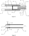
- Figure 3 is a schematic diagram of the cartomiser 30 of the e-cigarette 10 of Figure 1 in accordance with some embodiments of the invention.
- Figure 3 can generally be regarded as a cross-section in a plane through the longitudinal axis LA of the e-cigarette 10. Note that various components and details of the cartomiser 30, such as wiring and more complex shaping, have been omitted from Figure 3 for reasons of clarity.
- the cartomiser 30 includes an air passage 355 extending along the central (longitudinal) axis of the cartomiser 30 from the mouthpiece 35 to the connector 25A for joining the cartomiser 30 to the body 20.
- a reservoir of liquid 360 is provided around the air passage 335. This reservoir 360 may be implemented, for example, by providing cotton or foam soaked in liquid.
- the cartomiser 30 also includes a heater 365 for heating liquid from reservoir 360 to generate vapour to flow through air passage 355 and out through mouthpiece 35 in response to a user inhaling on the e-cigarette 10.
- the heater 365 is powered through lines 366 and 367, which are in turn connected to opposing polarities (positive and negative, or vice versa) of the battery 210 of the main body 20 via connector 25A (the details of the wiring between the power lines 366 and 367 and connector 25A are omitted from Figure 3 ).
- the connector 25A includes an inner electrode 375, which may be silver-plated or made of some other suitable metal or conducting material.
- the inner electrode 375 contacts the electrical contact 250 of the body 20 to provide a first electrical path between the cartomiser 30 and the body 20.
- the inner electrode 375 pushes against the electrical contact 250 so as to compress the coil spring 255, thereby helping to ensure good electrical contact between the inner electrode 375 and the electrical contact 250.
- the inner electrode 375 is surrounded by an insulating ring 372, which may be made of plastic, rubber, silicone, or any other suitable material.
- the insulating ring is surrounded by the cartomiser connector 370, which may be silver-plated or made of some other suitable metal or conducting material.
- the cartomiser connector 370 contacts the body connector 240 of the body 20 to provide a second electrical path between the cartomiser 30 and the body 20.
- the inner electrode 375 and the cartomiser connector 370 serve as positive and negative terminals (or vice versa) for supplying power from the battery 210 in the body 20 to the heater 365 in the cartomiser 30 via supply lines 366 and 367 as appropriate.
- the cartomiser connector 370 is provided with two lugs or tabs 380A, 380B, which extend in opposite directions away from the longitudinal axis of the e-cigarette 10. These tabs are used to provide a bayonet fitting in conjunction with the body connector 240 for connecting the cartomiser 30 to the body 20.
- This bayonet fitting provides a secure and robust connection between the cartomiser 30 and the body 20, so that the cartomiser and body are held in a fixed position relative to one another, with minimal wobble or flexing, and the likelihood of any accidental disconnection is very small.
- the bayonet fitting provides simple and rapid connection and disconnection by an insertion followed by a rotation for connection, and a rotation (in the reverse direction) followed by withdrawal for disconnection. It will be appreciated that other embodiments may use a different form of connection between the body 20 and the cartomiser 30, such as a snap fit or a screw connection.
- Figure 4 is a schematic diagram of certain details of the connector 25B at the end of the body 20 in accordance with some embodiments of the invention (but omitting for clarity most of the internal structure of the connector as shown in Figure 2 , such as trestle 260).
- Figure 4 shows the external housing 201 of the body 20, which generally has the form of a cylindrical tube.
- This external housing 201 may comprise, for example, an inner tube of metal with an outer covering of paper or similar.
- the external housing 201 may also comprise the manual activation device 265 (not shown in Figure 4 ) so that the manual activation device 265 is easily accessible to the user.
- the body connector 240 extends from this external housing 201 of the body 20.
- the body connector 240 as shown in Figure 4 comprises two main portions, a shaft portion 241 in the shape of a hollow cylindrical tube, which is sized to fit just inside the external housing 201 of the body 20, and a lip portion 242 which is directed in a radially outward direction, away from the main longitudinal axis (LA) of the e-cigarette.
- a collar or sleeve 290 Surrounding the shaft portion 241 of the body connector 240, where the shaft portion does not overlap with the external housing 201, is a collar or sleeve 290, which is again in a shape of a cylindrical tube.
- the collar 290 is retained between the lip portion 242 of the body connector 240 and the external housing 201 of the body, which together prevent movement of the collar 290 in an axial direction (i.e. parallel to axis LA). However, collar 290 is free to rotate around the shaft portion 241 (and hence also axis LA).
- the cap 225 is provided with an air inlet hole to allow air to flow when a user inhales on the mouthpiece 35.
- the majority of air that enters the device when a user inhales flows through collar 290 and body connector 240 as indicated by the two arrows in Figure 4 .
- an electronic vapour provision system (EVPS) 10 or ⁇ aerosol delivery device' such as one of those described previously herein is adapted to provide plural versions of an aerosol.
- the aerosol delivery device comprises a detection processor (such as the control unit mentioned previously, operating under suitable software instructions).
- this detection processor is configured to detect a first phase of an inhalation by a user upon the aerosol delivery device, as will be described in more detail later herein.
- this first phase may be simply assumed, for example upon triggering delivery of vapour by the EVPS (e.g. activation of the EVPS by inhalation).
- the aerosol delivery device also comprises a control processor 62 (such as again the control unit mentioned previously, or a separate processor, operating under suitable software instructions) configured to generate a first version of an aerosol having at least a first property modified to a first version, within this first phase of the inhalation.
- This version of the aerosol may form an initial default output for the EVPS, particularly if the first phase is simply assumed. The first property and the modification will be discussed later herein.
- the detection processor is configured to detect a second phase of the inhalation, as described later herein, and the control processor is configured to generate a second version of the aerosol having at least the first property modified to a second, different version in response to detection of the second phase of the inhalation.
- the first property is aerosol particle size, and typically the aerosol particle size of the first version of the aerosol is smaller than the second version of the aerosol. The reason for this arrangement is described later herein.
- the aerosol particle size can be changed by in turn changing a property of the aerosol generator. Depending on the type of generator, this may either involve changing a temperature of a heater used to generate the aerosol, or changing a frequency of a vibrator used to generate the aerosol.
- the temperature of the heater can increase the rate of vaporisation and this results in larger aerosol particle sizes.
- potentially decreasing the temperature of the heater may cause more rapid droplet formation and coalescence out of pure vapour form, resulting in larger aerosol particle sizes within the EVPS.
- the approach that is more appropriate for the payload used by the EVPS may therefore be selected, for example at manufacture, automatically (where payloads are interchangeable and detectable) or via a suitable user interface (as described later herein).
- inhalation by the user is detected using an airflow detector 215, or equivalently by a detector for any suitable proxy for airflow such as air speed or dynamic pressure.
- the first phase of the inhalation occurs until the airflow is above a first threshold level (Th1), and/or the airflow reaches a peak level (Peak).
- Th1 first threshold level
- Paak peak level
- the first phase assumes relatively strong or high initial airflow, which will typically (but not necessarily) reach an empirically determined threshold level indicative of this strong initial phase. Meanwhile, whether this threshold is met (or detected for), the airflow from the inhalation will, at some point, peak; this may be an instantaneous peak or a smoothed peak (as a non-limiting example, averaged over a rolling window of 0.1 or 0.2 seconds).
- the second phase of the inhalation occurs after airflow drops below a second threshold level (Th2), and/or the airflow reaches a peak level (Peak). Again if used, then the peak may be instantaneous or smoothed, as above.
- the first phase can be assumed until the second phase is detected, and as such optionally the completion of the first phase need not be separately detected at all.
- the transition is clear and in effect instantaneous.
- the EVPS may either continue in the first phase, or use this intervening time to transition towards or into the second phase (e.g. by moving to a neutral or transitional heater temperature, or vibration frequency).
- Various possible intervening times are represented in Figure 5 by horizontal arrowed lines.
- the effect of these embodiments is that a first version of the aerosol with typically smaller aerosol particles is produced during a first detected or assumed inhalation phase, and then in response to detection of the second inhalation phase a second version of the aerosol with typically larger aerosol particles is produced.
- the air inhaled during the initial part of the inhalation may have relatively higher velocity particles and will tend to reach the lungs during an inhalation whilst the air inhaled during the latter part of the inhalation may have relatively lower velocity particles and will tend to reach the mouth.
- different versions of aerosols adapted for delivery to the lungs or to the mouth can be delivered during different phases of the inhalation to increase the effectiveness of the delivery (for example including / increasing the proportion of nicotine in the first phase, and including / increasing the proportion of flavouring in the second phase, and/or excluding / reducing the proportion of flavour in the first phase, and excluding / reducing the proportion of nicotine in the second phase).
- smaller particles will tend to reach the lungs (and particularly the deep lungs where the air pathways narrow) whilst larger particles will tend to reach the mouth.
- providing smaller particles during the higher velocity first phase of inhalation will improve delivery of vapour to the lungs, and hence delivery of an active ingredient into the bloodstream, whilst providing larger particles during the lower velocity second phase of inhalation will improve delivery of vapour to the mouth, and hence delivery of flavour.
- embodiments of the present invention differentiate the generated aerosol during different phases of inhalation, targeting the lungs during the initial high velocity part of the inhalation, and targeting the mouth during the lower velocity end part of the inhalation.
- this can be done by controlling the heater temperature to create smaller and then larger particle sizes (or equally by control of a vibration atomiser), but potentially also or instead by switching between payloads during the inhalation (for example with a nicotine payload first, then a flavour payload second) by having two wicks, heaters or the like.
- different payloads may be used for the first and second inhalation phases to exploit the existing tendency toward delivery to the lungs in the first phase, and delivery to the mouth in the second phase, and may optionally also be differentiated by particle size to increase this tendency further, as explained previously herein.
- the first property is the payload that is being aerosolised and hence the constituents of the aeosol. It will be appreciated that when this is in addition to differentiating aerosol size, this would be a second property or a parallel first property, but otherwise may be considered the same.
- the EVPS comprises two aerosol generators each in connection to a respective one of two payload sources, and the control processor is configured to generate the first and second versions of the aerosol by selectively activating each of the aerosol generators to generate a respective aerosol comprising a respective payload (e.g. different constituents and/or ratios of constituents, for example changing the presence or level of nicotine and flavouring).
- a respective payload e.g. different constituents and/or ratios of constituents, for example changing the presence or level of nicotine and flavouring.
- control processor is then configured to effectively change the balance of the mix in response to detection of the second phase, and optionally in response to detection of completion of the first phase (for example by transitioning to a more even mix in a transitional period between phases, where one occurs).
- the two aerosol generators may not necessarily use the same generation mechanism, but that where at least a first aerosol generator is a heater it is in thermal connection with at least a portion of the respective payload, and where at least a first aerosol generator is a vibrator it is in mechanical connection with at least a portion of the respective payload.
- control processor is configured to measure airflow during a plurality of inhalations of the user, and the control processor is configured to model one or more inhalation airflow profiles of the user based upon these measurements.
- the or each profile is indicative of the typical behaviour of the user of the EVPS during inhalation.
- An inhalation airflow profile describes the velocity and/or amount of air inhaled through the electronic cigarette of the EVPS over the course of a puff by the user.
- An inhalation airflow profile may optionally be defined parametrically, to varying degrees of approximation.
- a profile may thus define a target shape of an inhalation as a time history or curve, or may define the peak airflow (or a similar measure of intensity) and the duration for the inhalation profile, or may define the integral of the airflow and the time, in either case optionally together with one or more further parameters responsive to the inhalation curve (such as a timing for a peak within the inhalation).
- Such profiles may thus characterise a short, low-dosage puff, or a long, higher dosage puff, or any other type or style of inhalation by the user.
- the profiles may vary depending on whether the user's inhalation is shallow or deep.
- the profile may be of arbitrary length, depending on the corresponding inhalation behaviour, and the airflow parameter described by the profile may vary over that time as the characteristics of the user's inhalation varies.
- a profile may be predefined at manufacture or by a distributor, or may be loaded later by a user (as described later herein).
- Profile data may be stored in a local data storage such as RAM or flash memory.
- the inhalation performed by a user may thus be compared to the profile description, whether this is by tracing an inhalation with respect to a time history or curve, or comparing the difference between a target profile position on an inhalation intensity / time plot and the user's current position, either after an inhalation is complete, or as it progresses.
- control processor is configured to compare airflow measurements to the one or more modelled inhalation airflow profiles, and if the measurement matches a modelled inhalation airflow profile to within a predetermined tolerance, then the control processor is configured to predict one or more of the start of the second phase of inhalation, and the end of the first phase of inhalation, based on that modelled inhalation airflow profile.
- the closest existing model could be selected.
- this could itself be subject to matching to a predetermined tolerance, outside which either a default behaviour is used or an additional model is initiated using the current measurements, thereby adapting to different styles of the user.
- the integral under the graph represents the amount of air inhaled, and hence over time is indicative of cumulative inhalation and hence the speed and depth of inhalation. Consequently any of the timing at which Th1 is met, and/or the level of the peak and/or the timing of the peak, and/or the integral itself, and/or initial the gradient of the airflow, and/or the timing at which Th2 is met may be used to characterise a profile and select a closest modelled profile and/or (in a training mode) to select or create a profile to update with this new data.
- the system as described herein may be a self-contained system in which an aerosol delivery device such as an e-cigarette comprises the detection and control processors and any required data storage, but optionally the system may comprise two components, such as an aerosol delivery device 10 and a mobile phone or similar device (such as a tablet) 100 operable to communicate with the e-cigarette, for example via a Bluetooth ® scheme.
- an aerosol delivery device such as an e-cigarette
- a mobile phone or similar device such as a tablet
- the mobile phone may then comprise one or more of the profile storage / selection / training means (e.g. suitable RAM, flash memory and processor), the detection processor, and the control processor, with input measurement data and output commands as appropriate being communicated by the Bluetooth ® scheme between the e-cigarette and mobile phone.
- the profile storage / selection / training means e.g. suitable RAM, flash memory and processor
- the detection processor e.g., the detection processor
- the control processor e.g. suitable RAM, flash memory and processor
- inhalation profiles may also be downloaded, or optionally created and/or curated, using a suitable interface on the mobile phone.
- an aerosol delivery system comprises a mobile communications device operable to wirelessly communicate with the aerosol delivery device, the mobile communications device comprising one or more of the detection processor and the control processor.
- the detection processor and/or control processor may be provided by a CPU of the mobile device operating under suitable software instruction. It will also be appreciated that the role of either the detection processor and/or the control processor may be shared between multiple CPUs, either in the phone, in the EVPS or distributed between the two.
- a method of control for an aerosol delivery system comprises:
- a conventional equivalent device may be implemented in the form of a computer program product comprising processor implementable instructions stored on a non-transitory machine-readable medium such as a floppy disk, optical disk, hard disk, PROM, RAM, flash memory or any combination of these or other storage media, or realised in hardware as an ASIC (application specific integrated circuit) or an FPGA (field programmable gate array) or other configurable circuit suitable to use in adapting the conventional equivalent device.
- a computer program may be transmitted via data signals on a network such as an Ethernet, a wireless network, the Internet, or any combination of these or other networks.
Landscapes
- Engineering & Computer Science (AREA)
- Computer Networks & Wireless Communication (AREA)
- Medicinal Preparation (AREA)
- Pharmaceuticals Containing Other Organic And Inorganic Compounds (AREA)
Abstract
Description
- The present disclosure relates to electronic aerosol provision systems such as nicotine delivery systems (e.g. electronic cigarettes and the like) and a corresponding method of aerosol provision.
- Electronic aerosol provision systems such as electronic cigarettes (e-cigarettes) generally contain a reservoir of a source liquid containing a formulation, typically including nicotine, from which an aerosol is generated, e.g. through heat vaporisation. An aerosol source for an aerosol provision system may thus comprise a heater having a heating element arranged to receive source liquid from the reservoir, for example through wicking / capillary action. Other source materials may be similarly heated to create an aerosol, such as botanical matter, or a gel comprising an active ingredient and/or flavouring. Hence more generally, the e-cigarette may be thought of as comprising or receiving a payload for heat vaporisation.
- While a user inhales on the device, electrical power is supplied to the heating element to vaporise the aerosol source (a portion of the payload) in the vicinity of the heating element, to generate an aerosol for inhalation by the user. Such devices are usually provided with one or more air inlet holes located away from a mouthpiece end of the system. When a user sucks on a mouthpiece connected to the mouthpiece end of the system, air is drawn in through the inlet holes and past the aerosol source. There is a flow path connecting between the aerosol source and an opening in the mouthpiece so that air drawn past the aerosol source continues along the flow path to the mouthpiece opening, carrying some of the aerosol from the aerosol source with it. The aerosol-carrying air exits the aerosol provision system through the mouthpiece opening for inhalation by the user.
- Usually an electric current is supplied to the heater when a user is drawing/ puffing on the device. Typically, the electric current is supplied to the heater, e.g. resistance heating element, in response to either the activation of an airflow sensor along the flow path as the user inhales/draw/puffs or in response to the activation of a button by the user. The heat generated by the heating element is used to vaporise a formulation. The released vapour mixes with air drawn through the device by the puffing consumer and forms an aerosol.. Alternatively or in addition, the heating element is used to heat but typically not burn a botanical such as tobacco, to release active ingredients thereof as a vapour / aerosol.
- The amount of active ingredient that successfully reaches the user's bloodstream will depend on how well the vaporised / aerosolised payload reaches the user's lungs; meanwhile the flavour experienced by the user will depend on how well the aerosolised payload interacts with the user's mouth. These are potentially contradictory requirements for the payload and/or the providing device.
- Various approaches are described herein which seek to help address or mitigate this contradictory requirement.
- In a first aspect, method of control for an aerosol delivery system is provided in accordance with
claim 1. - In another aspect, an aerosol delivery system is provided in accordance with claim 17.
- Further respective aspects and features of the invention are defined in the appended claims.
- Embodiments of the present invention will now be described by way of example with reference to the accompanying drawings, in which:
-
Figure 1 is a schematic diagram of an aerosol delivery device in accordance with an embodiment of the present invention. -
Figure 2 is a schematic diagram of an aerosol delivery device in accordance with an embodiment of the present invention. -
Figure 3 is a schematic diagram of an aerosol delivery device in accordance with an embodiment of the present invention. -
Figure 4 is a schematic diagram of an aerosol delivery device in accordance with an embodiment of the present invention. -
Figure 5 is a schematic diagram of measured airflow in accordance with an embodiment of the present invention. -
Figure 6 is a schematic diagram of an aerosol delivery system in accordance with an embodiment of the present invention. -
Figure 7 is a flow diagram of a method of control for an aerosol delivery system in accordance with an embodiment of the present invention. - An electronic aerosol provision system and method are disclosed. In the following description, a number of specific details are presented in order to provide a thorough understanding of the embodiments of the present invention. It will be apparent, however, to a person skilled in the art that these specific details need not be employed to practice the present invention. Conversely, specific details known to the person skilled in the art are omitted for the purposes of clarity where appropriate.
- As described above, the present disclosure relates to an aerosol provision system (e.g. a non-combustible aerosol provision system) or electronic vapour provision system (EVPS), such as an e-cigarette. Throughout the following description the term "e-cigarette" is sometimes used but this term may be used interchangeably with (electronic) aerosol/vapour provision system. Similarly the terms `vapour' and 'aerosol' are referred to equivalently herein.
- Generally, the electronic vapour / aerosol provision system may be an electronic cigarette, also known as a vaping device or electronic nicotine delivery system (END), although it is noted that the presence of nicotine in the aerosolisable material is not a requirement. In some embodiments, a non-combustible aerosol provision system is a tobacco heating system, also known as a heat-not-burn system. In some embodiments, the non-combustible aerosol provision system is a hybrid system to generate aerosol using a combination of aerosolisable materials, one or a plurality of which may be heated. Each of the aerosolisable materials may be, for example, in the form of a solid, liquid or gel and may or may not contain nicotine. In some embodiments, the hybrid system comprises a liquid or gel aerosolisable material and a solid aerosolisable material. The solid aerosolisable material may comprise, for example, tobacco or a non-tobacco product. Meanwhile in some embodiments, the non-combustible aerosol provision system generates a vapour / aerosol from one or more such aerosolisable materials.
- Typically, the non-combustible aerosol provision system may comprise a non-combustible aerosol provision device and an article for use with the non-combustible aerosol provision system. However, it is envisaged that articles which themselves comprise a means for powering an aerosol generating component may themselves form the non-combustible aerosol provision system. In one embodiment, the non-combustible aerosol provision device may comprise a power source and a controller. The power source may be an electric power source or an exothermic power source. In one embodiment, the exothermic power source comprises a carbon substrate which may be energised so as to distribute power in the form of heat to an aerosolisable material or heat transfer material in proximity to the exothermic power source. In one embodiment, the power source, such as an exothermic power source, is provided in the article so as to form the non-combustible aerosol provision. In one embodiment, the article for use with the non-combustible aerosol provision device may comprise an aerosolisable material.
- In some embodiments, the aerosol generating component is a heater capable of interacting with the aerosolisable material so as to release one or more volatiles from the aerosolisable material to form an aerosol. In one embodiment, the aerosol generating component is capable of generating an aerosol from the aerosolisable material without heating. For example, the aerosol generating component may be capable of generating an aerosol from the aerosolisable material without applying heat thereto, for example via one or more of vibrational, mechanical, pressurisation or electrostatic means.
- In some embodiments, the aerosolisable material may comprise an active material, an aerosol forming material and optionally one or more functional materials. The active material may comprise nicotine (optionally contained in tobacco or a tobacco derivative) or one or more other non-olfactory physiologically active materials. A non-olfactory physiologically active material is a material which is included in the aerosolisable material in order to achieve a physiological response other than olfactory perception. The aerosol forming material may comprise one or more of glycerine, glycerol, propylene glycol, diethylene glycol, triethylene glycol, tetraethylene glycol, 1,3-butylene glycol, erythritol, meso-Erythritol, ethyl vanillate, ethyl laurate, a diethyl suberate, triethyl citrate, triacetin, a diacetin mixture, benzyl benzoate, benzyl phenyl acetate, tributyrin, lauryl acetate, lauric acid, myristic acid, and propylene carbonate. The one or more functional materials may comprise one or more of flavours, carriers, pH regulators, stabilizers, and/or antioxidants.
- In some embodiments, the article for use with the non-combustible aerosol provision device may comprise aerosolisable material or an area for receiving aerosolisable material. In one embodiment, the article for use with the non-combustible aerosol provision device may comprise a mouthpiece. The area for receiving aerosolisable material may be a storage area for storing aerosolisable material. For example, the storage area may be a reservoir. In one embodiment, the area for receiving aerosolisable material may be separate from, or combined with, an aerosol generating area.
-
Figure 1 is a schematic diagram of an electronic vapour /aerosol provision system such as an e-cigarette 10 in accordance with some embodiments of the invention (not to scale). The e-cigarette has a generally cylindrical shape, extending along a longitudinal axis indicated by dashed line LA, and comprises two main components, namely abody 20 and acartomiser 30. The cartomiser includes an internal chamber containing a reservoir of a payload such as for example a liquid comprising nicotine, a vaporiser (such as a heater), and amouthpiece 35. References to 'nicotine' hereafter will be understood to be merely exemplary and can be substituted with any suitable active ingredient. References to `liquid' as a payload hereafter will be understood to be merely exemplary and can be substituted with any suitable payload such as botanical matter (for example tobacco that is to be heated rather than burned), or a gel comprising an active ingredient and/or flavouring. The reservoir may be a foam matrix or any other structure for retaining the liquid until such time that it is required to be delivered to the vaporiser. In the case of a liquid / flowing payload, the vaporiser is for vaporising the liquid, and thecartomiser 30 may further include a wick or similar facility to transport a small amount of liquid from the reservoir to a vaporising location on or adjacent the vaporiser. In the following, a heater is used as a specific example of a vaporiser. However, it will be appreciated that other forms of vaporiser (for example, those which utilise ultrasonic waves) could also be used and it will also be appreciated that the type of vaporiser used may also depend on the type of payload to be vaporised. - The
body 20 includes a re-chargeable cell or battery to provide power to thee-cigarette 10 and a circuit board for generally controlling the e-cigarette. When the heater receives power from the battery, as controlled by the circuit board, the heater vaporises the liquid and this vapour is then inhaled by a user through themouthpiece 35. In some specific embodiments the body is further provided with amanual activation device 265, e.g. a button, switch, or touch sensor located on the outside of the body. - The
body 20 andcartomiser 30 may be detachable from one another by separating in a direction parallel to the longitudinal axis LA, as shown inFigure 1 , but are joined together when thedevice 10 is in use by a connection, indicated schematically inFigure 1 as 25A and 25B, to provide mechanical and electrical connectivity between thebody 20 and thecartomiser 30. Theelectrical connector 25B on thebody 20 that is used to connect to thecartomiser 30 also serves as a socket for connecting a charging device (not shown) when thebody 20 is detached from thecartomiser 30. The other end of the charging device may be plugged into a USB socket to recharge the cell in thebody 20 of thee-cigarette 10. In other implementations, a cable may be provided for direct connection between theelectrical connector 25B on thebody 20 and a USB socket. - The
e-cigarette 10 is provided with one or more holes (not shown inFigure 1 ) for air inlets. These holes connect to an air passage through the e-cigarette 10 to themouthpiece 35. When a user inhales through themouthpiece 35, air is drawn into this air passage through the one or more air inlet holes, which are suitably located on the outside of the e-cigarette. When the heater is activated to vaporise the nicotine from the cartridge, the airflow passes through, and combines with, the generated vapour, and this combination of airflow and generated vapour then passes out of themouthpiece 35 to be inhaled by a user. Except in single-use devices, thecartomiser 30 may be detached from thebody 20 and disposed of when the supply of liquid is exhausted (and replaced with another cartomiser if so desired). - It will be appreciated that the e-cigarette 10 shown in
Figure 1 is presented by way of example, and various other implementations can be adopted. For example, in some embodiments, thecartomiser 30 is provided as two separable components, namely a cartridge comprising the liquid reservoir and mouthpiece (which can be replaced when the liquid from the reservoir is exhausted), and a vaporiser comprising a heater (which is generally retained). As another example, the charging facility may connect to an additional or alternative power source, such as a car cigarette lighter. -
Figure 2 is a schematic (simplified) diagram of thebody 20 of thee-cigarette 10 ofFigure 1 in accordance with some embodiments of the invention.Figure 2 can generally be regarded as a cross-section in a plane through the longitudinal axis LA of thee-cigarette 10. Note that various components and details of the body, e.g. such as wiring and more complex shaping, have been omitted fromFigure 2 for reasons of clarity. - The
body 20 includes a battery orcell 210 for powering the e-cigarette 10 in response to a user activation of the device. Additionally, thebody 20 includes a control unit (not shown inFigure 2 ), for example a chip such as an application specific integrated circuit (ASIC) or microcontroller, for controlling thee-cigarette 10. The microcontroller or ASIC includes a CPU or micro-processor. The operations of the CPU and other electronic components are generally controlled at least in part by software programs running on the CPU (or other component). Such software programs may be stored in non-volatile memory, such as ROM, which can be integrated into the microcontroller itself, or provided as a separate component. The CPU may access the ROM to load and execute individual software programs as and when required. The microcontroller also contains appropriate communications interfaces (and control software) for communicating as appropriate with other devices in thebody 10. - The
body 20 further includes acap 225 to seal and protect the far (distal) end of thee-cigarette 10. Typically there is an air inlet hole provided in or adjacent to thecap 225 to allow air to enter thebody 20 when a user inhales on themouthpiece 35. The control unit or ASIC may be positioned alongside or at one end of thebattery 210. In some embodiments, the ASIC is attached to asensor unit 215 to detect an inhalation on mouthpiece 35 (or alternatively thesensor unit 215 may be provided on the ASIC itself). An air path is provided from the air inlet through the e-cigarette, past theairflow sensor 215 and the heater (in the vaporiser or cartomiser 30), to themouthpiece 35. Thus when a user inhales on the mouthpiece of the e-cigarette, the CPU detects such inhalation based on information from theairflow sensor 215. - At the opposite end of the
body 20 from thecap 225 is theconnector 25B for joining thebody 20 to thecartomiser 30. Theconnector 25B provides mechanical and electrical connectivity between thebody 20 and thecartomiser 30. Theconnector 25B includes abody connector 240, which is metallic (silver-plated in some embodiments) to serve as one terminal for electrical connection (positive or negative) to thecartomiser 30. Theconnector 25B further includes anelectrical contact 250 to provide a second terminal for electrical connection to thecartomiser 30 of opposite polarity to the first terminal, namelybody connector 240. Theelectrical contact 250 is mounted on acoil spring 255. When the body20 is attached to thecartomiser 30, theconnector 25A on thecartomiser 30 pushes against theelectrical contact 250 in such a manner as to compress the coil spring in an axial direction, i.e. in a direction parallel to (co-aligned with) the longitudinal axis LA. In view of the resilient nature of thespring 255, this compression biases thespring 255 to expand, which has the effect of pushing theelectrical contact 250 firmly againstconnector 25A of thecartomiser 30, thereby helping to ensure good electrical connectivity between thebody 20 and thecartomiser 30. Thebody connector 240 and theelectrical contact 250 are separated by atrestle 260, which is made of a non-conductor (such as plastic) to provide good insulation between the two electrical terminals. Thetrestle 260 is shaped to assist with the mutual mechanical engagement ofconnectors - As mentioned above, a
button 265, which represents a form ofmanual activation device 265, may be located on the outer housing of thebody 20. Thebutton 265 may be implemented using any appropriate mechanism which is operable to be manually activated by the user - for example, as a mechanical button or switch, a capacitive or resistive touch sensor, and so on. It will also be appreciated that themanual activation device 265 may be located on the outer housing of thecartomiser 30, rather than the outer housing of thebody 20, in which case, themanual activation device 265 may be attached to the ASIC via theconnections button 265 might also be located at the end of thebody 20, in place of (or in addition to)cap 225. -
Figure 3 is a schematic diagram of thecartomiser 30 of thee-cigarette 10 ofFigure 1 in accordance with some embodiments of the invention.Figure 3 can generally be regarded as a cross-section in a plane through the longitudinal axis LA of thee-cigarette 10. Note that various components and details of thecartomiser 30, such as wiring and more complex shaping, have been omitted fromFigure 3 for reasons of clarity. - The
cartomiser 30 includes anair passage 355 extending along the central (longitudinal) axis of the cartomiser 30 from themouthpiece 35 to theconnector 25A for joining thecartomiser 30 to thebody 20. A reservoir ofliquid 360 is provided around the air passage 335. Thisreservoir 360 may be implemented, for example, by providing cotton or foam soaked in liquid. Thecartomiser 30 also includes aheater 365 for heating liquid fromreservoir 360 to generate vapour to flow throughair passage 355 and out throughmouthpiece 35 in response to a user inhaling on thee-cigarette 10. Theheater 365 is powered throughlines battery 210 of themain body 20 viaconnector 25A (the details of the wiring between thepower lines connector 25A are omitted fromFigure 3 ). - The
connector 25A includes aninner electrode 375, which may be silver-plated or made of some other suitable metal or conducting material. When thecartomiser 30 is connected to thebody 20, theinner electrode 375 contacts theelectrical contact 250 of thebody 20 to provide a first electrical path between the cartomiser 30 and thebody 20. In particular, as theconnectors inner electrode 375 pushes against theelectrical contact 250 so as to compress thecoil spring 255, thereby helping to ensure good electrical contact between theinner electrode 375 and theelectrical contact 250. - The
inner electrode 375 is surrounded by an insulatingring 372, which may be made of plastic, rubber, silicone, or any other suitable material. The insulating ring is surrounded by thecartomiser connector 370, which may be silver-plated or made of some other suitable metal or conducting material. When thecartomiser 30 is connected to thebody 20, thecartomiser connector 370 contacts thebody connector 240 of thebody 20 to provide a second electrical path between the cartomiser 30 and thebody 20. In other words, theinner electrode 375 and thecartomiser connector 370 serve as positive and negative terminals (or vice versa) for supplying power from thebattery 210 in thebody 20 to theheater 365 in thecartomiser 30 viasupply lines - The
cartomiser connector 370 is provided with two lugs ortabs e-cigarette 10. These tabs are used to provide a bayonet fitting in conjunction with thebody connector 240 for connecting thecartomiser 30 to thebody 20. This bayonet fitting provides a secure and robust connection between the cartomiser 30 and thebody 20, so that the cartomiser and body are held in a fixed position relative to one another, with minimal wobble or flexing, and the likelihood of any accidental disconnection is very small. At the same time, the bayonet fitting provides simple and rapid connection and disconnection by an insertion followed by a rotation for connection, and a rotation (in the reverse direction) followed by withdrawal for disconnection. It will be appreciated that other embodiments may use a different form of connection between thebody 20 and thecartomiser 30, such as a snap fit or a screw connection. -
Figure 4 is a schematic diagram of certain details of theconnector 25B at the end of thebody 20 in accordance with some embodiments of the invention (but omitting for clarity most of the internal structure of the connector as shown inFigure 2 , such as trestle 260). In particular,Figure 4 shows the external housing 201 of thebody 20, which generally has the form of a cylindrical tube. This external housing 201 may comprise, for example, an inner tube of metal with an outer covering of paper or similar. The external housing 201 may also comprise the manual activation device 265 (not shown inFigure 4 ) so that themanual activation device 265 is easily accessible to the user. - The
body connector 240 extends from this external housing 201 of thebody 20. Thebody connector 240 as shown inFigure 4 comprises two main portions, ashaft portion 241 in the shape of a hollow cylindrical tube, which is sized to fit just inside the external housing 201 of thebody 20, and alip portion 242 which is directed in a radially outward direction, away from the main longitudinal axis (LA) of the e-cigarette. Surrounding theshaft portion 241 of thebody connector 240, where the shaft portion does not overlap with the external housing 201, is a collar orsleeve 290, which is again in a shape of a cylindrical tube. Thecollar 290 is retained between thelip portion 242 of thebody connector 240 and the external housing 201 of the body, which together prevent movement of thecollar 290 in an axial direction (i.e. parallel to axis LA). However,collar 290 is free to rotate around the shaft portion 241 (and hence also axis LA). - As mentioned above, the
cap 225 is provided with an air inlet hole to allow air to flow when a user inhales on themouthpiece 35. However, in some embodiments the majority of air that enters the device when a user inhales flows throughcollar 290 andbody connector 240 as indicated by the two arrows inFigure 4 . - Referring again to
Figures 1 and 2 , in an embodiment of the present invention, an electronic vapour provision system (EVPS) 10 or `aerosol delivery device' such as one of those described previously herein is adapted to provide plural versions of an aerosol. - Accordingly, in embodiments of the present invention, the aerosol delivery device comprises a detection processor (such as the control unit mentioned previously, operating under suitable software instructions). Optionally, this detection processor is configured to detect a first phase of an inhalation by a user upon the aerosol delivery device, as will be described in more detail later herein. Alternatively this first phase may be simply assumed, for example upon triggering delivery of vapour by the EVPS (e.g. activation of the EVPS by inhalation).
- The aerosol delivery device also comprises a control processor 62 (such as again the control unit mentioned previously, or a separate processor, operating under suitable software instructions) configured to generate a first version of an aerosol having at least a first property modified to a first version, within this first phase of the inhalation. This version of the aerosol may form an initial default output for the EVPS, particularly if the first phase is simply assumed. The first property and the modification will be discussed later herein.
- The detection processor is configured to detect a second phase of the inhalation, as described later herein, and the control processor is configured to generate a second version of the aerosol having at least the first property modified to a second, different version in response to detection of the second phase of the inhalation.
- In embodiments of the present invention, the first property is aerosol particle size, and typically the aerosol particle size of the first version of the aerosol is smaller than the second version of the aerosol. The reason for this arrangement is described later herein.
- The aerosol particle size can be changed by in turn changing a property of the aerosol generator. Depending on the type of generator, this may either involve changing a temperature of a heater used to generate the aerosol, or changing a frequency of a vibrator used to generate the aerosol.
- For some payloads, increasing the temperature of the heater can increase the rate of vaporisation and this results in larger aerosol particle sizes. For other payloads, potentially decreasing the temperature of the heater may cause more rapid droplet formation and coalescence out of pure vapour form, resulting in larger aerosol particle sizes within the EVPS. The approach that is more appropriate for the payload used by the EVPS may therefore be selected, for example at manufacture, automatically (where payloads are interchangeable and detectable) or via a suitable user interface (as described later herein).
- Referring now to
Figure 5 , in embodiments of the present invention inhalation by the user is detected using anairflow detector 215, or equivalently by a detector for any suitable proxy for airflow such as air speed or dynamic pressure. - Using airflow as the example, but appreciating that airspeed, dynamic pressure or the like could be used instead, then the first phase of the inhalation occurs until the airflow is above a first threshold level (Th1), and/or the airflow reaches a peak level (Peak).
- Hence during an inhalation by the user, the first phase assumes relatively strong or high initial airflow, which will typically (but not necessarily) reach an empirically determined threshold level indicative of this strong initial phase. Meanwhile, whether this threshold is met (or detected for), the airflow from the inhalation will, at some point, peak; this may be an instantaneous peak or a smoothed peak (as a non-limiting example, averaged over a rolling window of 0.1 or 0.2 seconds).
- Meanwhile the second phase of the inhalation occurs after airflow drops below a second threshold level (Th2), and/or the airflow reaches a peak level (Peak). Again if used, then the peak may be instantaneous or smoothed, as above.
- It will be appreciated that optionally the first phase can be assumed until the second phase is detected, and as such optionally the completion of the first phase need not be separately detected at all. Clearly, where the first and second phases are delineated by the same event (e.g. peak inhalation) then the transition is clear and in effect instantaneous. Meanwhile if the first phase is deemed to be complete once the first threshold is reached (but before a peak is reached, or before the airflow falls below the second threshold, as appropriate), then the EVPS may either continue in the first phase, or use this intervening time to transition towards or into the second phase (e.g. by moving to a neutral or transitional heater temperature, or vibration frequency). Various possible intervening times are represented in
Figure 5 by horizontal arrowed lines. - The effect of these embodiments is that a first version of the aerosol with typically smaller aerosol particles is produced during a first detected or assumed inhalation phase, and then in response to detection of the second inhalation phase a second version of the aerosol with typically larger aerosol particles is produced.
- The reason behind this is that the inventors have appreciated that during the course of an inhalation on the EVPS (or similar devices), the air inhaled during the initial part of the inhalation may have relatively higher velocity particles and will tend to reach the lungs during an inhalation whilst the air inhaled during the latter part of the inhalation may have relatively lower velocity particles and will tend to reach the mouth. As a result, different versions of aerosols adapted for delivery to the lungs or to the mouth can be delivered during different phases of the inhalation to increase the effectiveness of the delivery (for example including / increasing the proportion of nicotine in the first phase, and including / increasing the proportion of flavouring in the second phase, and/or excluding / reducing the proportion of flavour in the first phase, and excluding / reducing the proportion of nicotine in the second phase). Similarly, smaller particles will tend to reach the lungs (and particularly the deep lungs where the air pathways narrow) whilst larger particles will tend to reach the mouth.
- Therefore, providing smaller particles during the higher velocity first phase of inhalation will improve delivery of vapour to the lungs, and hence delivery of an active ingredient into the bloodstream, whilst providing larger particles during the lower velocity second phase of inhalation will improve delivery of vapour to the mouth, and hence delivery of flavour.
- The result is that a similar amount of active ingredient and flavour can be delivered to the user by a smaller amount of vapour, because it is delivered more efficiently than if the aerosol particles are not differentiated in response to the inhalation profile of the user.
- In other words, embodiments of the present invention differentiate the generated aerosol during different phases of inhalation, targeting the lungs during the initial high velocity part of the inhalation, and targeting the mouth during the lower velocity end part of the inhalation. As described above, this can be done by controlling the heater temperature to create smaller and then larger particle sizes (or equally by control of a vibration atomiser), but potentially also or instead by switching between payloads during the inhalation (for example with a nicotine payload first, then a flavour payload second) by having two wicks, heaters or the like.
- Hence in embodiments of the present invention, different payloads may be used for the first and second inhalation phases to exploit the existing tendency toward delivery to the lungs in the first phase, and delivery to the mouth in the second phase, and may optionally also be differentiated by particle size to increase this tendency further, as explained previously herein.
- Hence in embodiments of the present invention, the first property is the payload that is being aerosolised and hence the constituents of the aeosol. It will be appreciated that when this is in addition to differentiating aerosol size, this would be a second property or a parallel first property, but otherwise may be considered the same.
- Accordingly, in an embodiment of the invention, the EVPS comprises two aerosol generators each in connection to a respective one of two payload sources, and the control processor is configured to generate the first and second versions of the aerosol by selectively activating each of the aerosol generators to generate a respective aerosol comprising a respective payload (e.g. different constituents and/or ratios of constituents, for example changing the presence or level of nicotine and flavouring).
- It will be appreciated that such activations can overlap to create a mix, and the control processor is then configured to effectively change the balance of the mix in response to detection of the second phase, and optionally in response to detection of completion of the first phase (for example by transitioning to a more even mix in a transitional period between phases, where one occurs).
- It will be appreciated that the two aerosol generators may not necessarily use the same generation mechanism, but that where at least a first aerosol generator is a heater it is in thermal connection with at least a portion of the respective payload, and where at least a first aerosol generator is a vibrator it is in mechanical connection with at least a portion of the respective payload.
- It will be appreciated that improving uptake of an active ingredient during a first, higher velocity and deep-lung phase of inhalation, by using smaller aerosol particle sizes and/or targeted selection of active payload, and improving sensation of flavour during a second lower velocity and shallower phase of inhalation, by using larger aerosol particle sizes and/or targeted selection of flavour payload, could be improved further by more accurately predicting at least the start of the second phase for the particular user; this is because there is likely to be a delay, either in temperature change and/or in vaporisation of a payload, during transition to the second phase; therefore by predicting when the second phase (and optionally the first phase) occur, this delay can potentially be accounted for or mitigated.
- Hence in embodiments of the present invention, the control processor is configured to measure airflow during a plurality of inhalations of the user, and the control processor is configured to model one or more inhalation airflow profiles of the user based upon these measurements.
- The or each profile is indicative of the typical behaviour of the user of the EVPS during inhalation.
- An inhalation airflow profile describes the velocity and/or amount of air inhaled through the electronic cigarette of the EVPS over the course of a puff by the user.
- An inhalation airflow profile may optionally be defined parametrically, to varying degrees of approximation. A profile may thus define a target shape of an inhalation as a time history or curve, or may define the peak airflow (or a similar measure of intensity) and the duration for the inhalation profile, or may define the integral of the airflow and the time, in either case optionally together with one or more further parameters responsive to the inhalation curve (such as a timing for a peak within the inhalation).
- Such profiles may thus characterise a short, low-dosage puff, or a long, higher dosage puff, or any other type or style of inhalation by the user. Similarly the profiles may vary depending on whether the user's inhalation is shallow or deep. Hence the profile may be of arbitrary length, depending on the corresponding inhalation behaviour, and the airflow parameter described by the profile may vary over that time as the characteristics of the user's inhalation varies.
- Optionally a profile may be predefined at manufacture or by a distributor, or may be loaded later by a user (as described later herein). Profile data may be stored in a local data storage such as RAM or flash memory.
- The inhalation performed by a user may thus be compared to the profile description, whether this is by tracing an inhalation with respect to a time history or curve, or comparing the difference between a target profile position on an inhalation intensity / time plot and the user's current position, either after an inhalation is complete, or as it progresses.
- Accordingly, the control processor is configured to compare airflow measurements to the one or more modelled inhalation airflow profiles, and if the measurement matches a modelled inhalation airflow profile to within a predetermined tolerance, then the control processor is configured to predict one or more of the start of the second phase of inhalation, and the end of the first phase of inhalation, based on that modelled inhalation airflow profile. Equivalently, instead of matching to a predetermined tolerance, the closest existing model could be selected. Optionally this could itself be subject to matching to a predetermined tolerance, outside which either a default behaviour is used or an additional model is initiated using the current measurements, thereby adapting to different styles of the user.
- Referring again to
Figure 5 , this time as an example inhalation profile, it will be appreciated that the integral under the graph represents the amount of air inhaled, and hence over time is indicative of cumulative inhalation and hence the speed and depth of inhalation. Consequently any of the timing at which Th1 is met, and/or the level of the peak and/or the timing of the peak, and/or the integral itself, and/or initial the gradient of the airflow, and/or the timing at which Th2 is met may be used to characterise a profile and select a closest modelled profile and/or (in a training mode) to select or create a profile to update with this new data. - Referring to
Figure 6 , it will be appreciated that the system as described herein may be a self-contained system in which an aerosol delivery device such as an e-cigarette comprises the detection and control processors and any required data storage, but optionally the system may comprise two components, such as anaerosol delivery device 10 and a mobile phone or similar device (such as a tablet) 100 operable to communicate with the e-cigarette, for example via a Bluetooth ® scheme. - The mobile phone may then comprise one or more of the profile storage / selection / training means (e.g. suitable RAM, flash memory and processor), the detection processor, and the control processor, with input measurement data and output commands as appropriate being communicated by the Bluetooth ® scheme between the e-cigarette and mobile phone.
- As suggested previously above, inhalation profiles may also be downloaded, or optionally created and/or curated, using a suitable interface on the mobile phone.
- Hence in embodiments of the present invention, an aerosol delivery system comprises a mobile communications device operable to wirelessly communicate with the aerosol delivery device, the mobile communications device comprising one or more of the detection processor and the control processor. In this case, it will be appreciated that the detection processor and/or control processor may be provided by a CPU of the mobile device operating under suitable software instruction. It will also be appreciated that the role of either the detection processor and/or the control processor may be shared between multiple CPUs, either in the phone, in the EVPS or distributed between the two.
- Referring now to
Figure 7 , a method of control for an aerosol delivery system comprises: - Optionally detecting a first phase of an inhalation by a user upon the aerosol delivery device, or simply assuming the first phase upon activation of the EVPS to deliver vapour;
- In a first step s710, generating a first version of an aerosol having at least a first property modified to a first version within the first phase of the inhalation;
- In a second step s720, detecting a second phase of the inhalation; and
- In a third step s730, generating a second version of the aerosol having at least the first property modified to a second, different version in response to detection of the second phase of the inhalation.
- It will be apparent to a person skilled in the art that variations in the above method corresponding to operation of the various embodiments of the apparatus as described and claimed herein are considered within the scope of the present invention, including but not limited to:
- the first property being aerosol particle size;
- ∘ the aerosol particle size of the first version being smaller than the second version;
- ∘ generating the first and second versions of the aerosol by changing a property of an aerosol generator to change the resulting aerosol particle size, the property of the aerosol generator being one selected from the list consisting of a temperature of a heater used to generate the aerosol, a frequency of a vibrator used to generate the aerosol, and a source of the aerosol (e.g. different aerosol paths, modes of generation, base materials etc).
- the first property being the payload being aerosolised.
- ∘ the payload of the first version comprising an ingredient whose active effect occurs when absorbed into the bloodstream, and the payload of the second version comprising an ingredient whose active effect occurs when tasted;
- ∘ the aerosol delivery device comprising two aerosol generators each in connection to a respective one of two payload sources, and the method comprising the step of generating the first and second versions of the aerosol by selectively activating each of the aerosol generators to generate a respective aerosol comprising a respective payload;
- ▪ at least a first aerosol generator being a heater, and in thermal connection with at least a portion of the respective payload;
- ▪ at least a first aerosol generator being a vibrator, and in mechanical connection with at least a portion of the respective payload;
- inhalation being detected using an airflow detector;
- ∘ the first phase of the inhalation occurring until the airflow is above a first threshold level;
- ∘ the first phase of the inhalation occurring until the airflow reaches a peak level;
- ∘ the second phase of the inhalation occurring after the airflow drops below a second threshold level;
- ∘ the second phase of the inhalation occurring after the airflow reaches a peak level;
- measuring airflow during a plurality of inhalations of the user, and modelling one or more inhalation airflow profiles of the user based upon these measurements; and
- measuring airflow during an inhalation of the user, comparing the measurement to the one or more modelled inhalation airflow profiles, and if the measurement matches a modelled inhalation airflow profiles to within a predetermined tolerance, predicting one or more selected from the list consisting of the end of the first phase of inhalation and the start of the second phase of inhalation.
- It will be appreciated that the above methods may be carried out on conventional hardware suitably adapted as applicable by software instruction or by the inclusion or substitution of dedicated hardware, such as for example e-cigarette or similar, or an e-cigarette operating in combination with a mobile phone or similar.
- Thus the required adaptation to existing parts of a conventional equivalent device may be implemented in the form of a computer program product comprising processor implementable instructions stored on a non-transitory machine-readable medium such as a floppy disk, optical disk, hard disk, PROM, RAM, flash memory or any combination of these or other storage media, or realised in hardware as an ASIC (application specific integrated circuit) or an FPGA (field programmable gate array) or other configurable circuit suitable to use in adapting the conventional equivalent device. Separately, such a computer program may be transmitted via data signals on a network such as an Ethernet, a wireless network, the Internet, or any combination of these or other networks.
- The various embodiments described herein are presented only to assist in understanding and teaching the claimed features. These embodiments are provided as a representative sample of embodiments only, and are not exhaustive and/or exclusive. It is to be understood that advantages, embodiments, examples, functions, features, structures, and/or other aspects described herein are not to be considered limitations on the scope of the invention as defined by the claims or limitations on equivalents to the claims, and that other embodiments may be utilised and modifications may be made without departing from the scope of the claimed invention. Various embodiments of the invention may suitably comprise, consist of, or consist essentially of, appropriate combinations of the disclosed elements, components, features, parts, steps, means, etc, other than those specifically described herein. In addition, this disclosure may include other inventions not presently claimed, but which may be claimed in future.
-
- 1. A method of control for an aerosol delivery system, comprising the steps of:
- generating a first version of an aerosol having at least a first property modified to a first version within a first phase of the inhalation;
- detecting a second phase of the inhalation; and
- generating a second version of the aerosol having at least the first property modified to a second, different version in response to detection of the second phase of the inhalation.
- 2. A method according to
clause 1 in which the first property is the constituents of the payload being aerosolised. - 3. A method according to
clause 2 in which the payload of the first version comprises an ingredient whose active effect occurs when absorbed into the bloodstream, and the payload of the second version comprises an ingredient whose active effect occurs when tasted. - 4. A method according to
clauses 2 or 3 in which the aerosol delivery device comprises two aerosol generators each in connection to a respective one of two payload sources; and the method comprises the step of:
generating the first and second versions of the aerosol by selectively activating each of the aerosol generators to generate a respective aerosol comprising a respective payload. - 5. A method according to clause 4 in which at least a first aerosol generator is a heater, and is in thermal connection with at least a portion of the respective payload.
- 6. A method according to clause 4 in which at least a first aerosol generator is a vibrator, and is in mechanical connection with at least a portion of the respective payload.
- 7. A method according to
clause 1 in which the first property is aerosol particle size. - 8. A method according to clause 7 in which the aerosol particle size of the first version is smaller than the second version.
- 9. A method according to clauses 7 or 8, comprising the step of
generating the first and second versions of the aerosol by changing a property of an aerosol generator to change the resulting aerosol particle size, the property of the aerosol generator being one selected from the list consisting of:- i. a temperature of a heater used to generate the aerosol
- ii. a frequency of a vibrator used to generate the aerosol; and
- iii. a source of the aerosol.
- 10. A method according to any one of the preceding clauses, in which inhalation is detected using an airflow detector.
- 11. A method according to
clause 10, in which the first phase of the inhalation occurs until the airflow is above a first threshold level. - 12. A method according to
clause 10 or 11, in which the first phase of the inhalation occurs until the airflow reaches a peak level. - 13. A method according to any one of
clauses 10 to 12, in which the second phase of the inhalation occurs after the airflow drops below a second threshold level. - 14. A method according to any one of
clauses 10 to 13, in which the second phase of the inhalation occurs after the airflow reaches a peak level. - 15. A method according to any one of the preceding clauses, comprising the steps of:
- measuring airflow during a plurality of inhalations of the user; and
- modelling one or more inhalation airflow profiles of the user based upon these measurements.
- 16. A method according to clause 15, comprising the steps of:
- measuring airflow during an inhalation of the user;
- comparing the measurement to the one or more modelled inhalation airflow profiles; and
- if the measurement matches a modelled inhalation airflow profiles to within a predetermined tolerance,
- predicting one or more selected from the list consisting of:
- i. the end of the first phase of inhalation; and
- ii. the start of the second phase of inhalation.
- 17. An aerosol delivery system, comprising:
- an aerosol delivery device;
- a control processor configured to generate a first version of an aerosol having at least a first property modified to a first version within a first phase of the inhalation;
- a detection processor configured to detect a second phase of the inhalation; and
- the control processor configured to generate a second version of the aerosol having at least the first property modified to a second, different version in response to detection of the second phase of the inhalation.
- 18. The aerosol delivery device of clause 17 in which the first property is the constituents of the payload being aerosolised.
- 19. The aerosol delivery system of clause 18 in which the aerosol delivery device comprises two aerosol generators each in connection to a respective one of two payload sources; and
the control processor is configured to generate the first and second versions of the aerosol by selectively activating each of the aerosol generators to generate a respective aerosol comprising a respective payload. - 20. The aerosol delivery system of clause 17 in which the first property is aerosol particle size.
- 21. The aerosol delivery system of
clause 20 in which the aerosol particle size of the first version is smaller than the second version. - 22. The aerosol delivery system of
clause 20 or clause 21, in which the control processor is configured to generate the first and second versions of the aerosol by changing a property of an aerosol generator to change the resulting aerosol particle size, the property of the aerosol generator being one selected from the list consisting of:- i. a temperature of a heater used to generate the aerosol
- ii. a frequency of a vibrator used to generate the aerosol; and
- iii. a source of the aerosol.
- 23. The aerosol delivery system of any one of clauses 17 to 22, in which inhalation is detected using an airflow detector.
- 24. The aerosol delivery system of any one of clauses 17 to 23, in which the first phase of the inhalation occurs until one or more from the list consisting of:
- i. the airflow being above a first threshold level; and
- ii. the airflow reaching a peak level.
- 25. The aerosol delivery system of any one of clauses 17 to 24, in which the second phase of the inhalation occurs after one or more from the list consisting of:
- i. the airflow dropping below a second threshold level; and
- ii. the airflow reaching a peak level.
- 26. The aerosol delivery system of any one of clauses 17 to 25, in which:
- the control processor is configured to measure airflow during a plurality of inhalations of the user; and
- the control processor is configured to model one or more inhalation airflow profiles of the user based upon these measurements.
- 27. The aerosol delivery system of clause 26, in which
- the control processor is configured to compare airflow measurements to the one or more modelled inhalation airflow profiles; and
- if the measurement matches a modelled inhalation airflow profiles to within a predetermined tolerance,
- the control processor is configured to predict one or more selected from the list consisting of:
- i. the end of the first phase of inhalation; and
- ii. the start of the second phase of inhalation.
- 28. The aerosol delivery system of any one of clauses 17 to 27, comprising:
- a mobile communications device operable to wirelessly communicate with the aerosol delivery device; and wherein
- the mobile communications device comprises one or more from the list consisting of:
- i. the detection processor; and
- ii. the control processor.
- 29. The aerosol delivery system of any one of clauses 17 to 28, comprising:
at least a first payload for aerosolisation by the aerosol delivery device.
Claims (13)
- A method of control for an aerosol delivery system, the method comprising the steps of:measuring airflow during a plurality of inhalations of a user of the aerosol provision system; andmodelling one or more inhalation airflow profiles of the user based upon these measurements.
- A method according to claim 1, wherein each inhalation airflow profile describes a velocity and/or amount of air inhaled through the aerosol provision system over the course of a puff by the user.
- A method according to any preceding claim, wherein each inhalation airflow profile defines a target shape of an inhalation as a time history or curve.
- A method according to any preceding claim, wherein each inhalation airflow profile defines a peak airflow for the inhalation profile.
- A method according to any preceding claim, wherein each inhalation airflow profile defines a duration for the inhalation profile.
- A method according to any preceding claim, wherein each inhalation airflow profile defines a timing for a peak within the inhalation.
- A method according to any preceding claim, wherein each inhalation airflow profile defines a timing at which the airflow drops below a threshold level (Th2).
- A method according to any preceding claim, wherein the method further comprises:
downloading at least one of the inhalation airflow profiles using an interface on a mobile phone which is in wireless communication with the aerosol provision system. - A method according to claim 8, wherein the method further comprises:
curating the at least one of the inhalation airflow profiles using the interface on the mobile phone - A method of control for an aerosol delivery system, the method comprising the steps of:comparing airflow measurements from a user of an aerosol provision system to one or more modelled inhalation airflow profiles; andmatching the measurements to a modelled inhalation airflow profile if the measurements match the modelled inhalation airflow profile to within a predetermined tolerance; or elseusing a default behaviour if the airflow measurements are outside the predetermined tolerance for each of the one or more modelled inhalation airflow profiles.
- A method according to claim 10, wherein comparing airflow measurements from the user of the aerosol provision system to the one or more modelled inhalation airflow profiles comprises comparing the airflow measurements as an inhalation progresses.
- The method according to any preceding claim, in which inhalation is detected using an airflow detector.
- An aerosol delivery system, comprising:an aerosol delivery device;a control processor configured to perform the method according to any preceding claim.
Applications Claiming Priority (3)
| Application Number | Priority Date | Filing Date | Title |
|---|---|---|---|
| GB201914945A GB201914945D0 (en) | 2019-10-16 | 2019-10-16 | Electronic aerosol provision system and method |
| EP20780287.7A EP4044844A1 (en) | 2019-10-16 | 2020-09-17 | Electronic aerosol provision system and method |
| PCT/GB2020/052246 WO2021074578A1 (en) | 2019-10-16 | 2020-09-17 | Electronic aerosol provision system and method |
Related Parent Applications (1)
| Application Number | Title | Priority Date | Filing Date |
|---|---|---|---|
| EP20780287.7A Division EP4044844A1 (en) | 2019-10-16 | 2020-09-17 | Electronic aerosol provision system and method |
Publications (2)
| Publication Number | Publication Date |
|---|---|
| EP4295878A2 true EP4295878A2 (en) | 2023-12-27 |
| EP4295878A3 EP4295878A3 (en) | 2024-06-26 |
Family
ID=68619707
Family Applications (2)
| Application Number | Title | Priority Date | Filing Date |
|---|---|---|---|
| EP20780287.7A Pending EP4044844A1 (en) | 2019-10-16 | 2020-09-17 | Electronic aerosol provision system and method |
| EP23196391.9A Pending EP4295878A3 (en) | 2019-10-16 | 2020-09-17 | Electronic aerosol provision system and method |
Family Applications Before (1)
| Application Number | Title | Priority Date | Filing Date |
|---|---|---|---|
| EP20780287.7A Pending EP4044844A1 (en) | 2019-10-16 | 2020-09-17 | Electronic aerosol provision system and method |
Country Status (7)
| Country | Link |
|---|---|
| US (2) | US20220378107A1 (en) |
| EP (2) | EP4044844A1 (en) |
| JP (2) | JP7414199B2 (en) |
| KR (2) | KR20230133984A (en) |
| CA (1) | CA3154928A1 (en) |
| GB (1) | GB201914945D0 (en) |
| WO (1) | WO2021074578A1 (en) |
Families Citing this family (1)
| Publication number | Priority date | Publication date | Assignee | Title |
|---|---|---|---|---|
| CN118450824A (en) * | 2021-11-10 | 2024-08-06 | 尼科创业贸易有限公司 | Aerosol delivery device with usage data monitoring |
Family Cites Families (6)
| Publication number | Priority date | Publication date | Assignee | Title |
|---|---|---|---|---|
| EP2460423A1 (en) | 2010-12-03 | 2012-06-06 | Philip Morris Products S.A. | An electrically heated aerosol generating system having improved heater control |
| UA114898C2 (en) * | 2011-10-27 | 2017-08-28 | Філіп Морріс Продактс С.А. | Aerosol generating system with improved aerosol production |
| CA2924114A1 (en) * | 2013-09-13 | 2015-03-19 | Nicodart, Inc. | Programmable electronic vaporizing apparatus and smoking cessation system |
| US10888119B2 (en) * | 2014-07-10 | 2021-01-12 | Rai Strategic Holdings, Inc. | System and related methods, apparatuses, and computer program products for controlling operation of a device based on a read request |
| US10398175B2 (en) * | 2014-12-11 | 2019-09-03 | Philip Morris Products S.A. | Inhaling device with user recognition based on inhalation behaviour |
| WO2019173923A1 (en) * | 2018-03-14 | 2019-09-19 | Canopy Growth Corporation | Vape devices, including cartridges, tablets, sensors, and controls for vape devices, and methods for making and using the same |
-
2019
- 2019-10-16 GB GB201914945A patent/GB201914945D0/en not_active Ceased
-
2020
- 2020-09-17 JP JP2022522941A patent/JP7414199B2/en active Active
- 2020-09-17 EP EP20780287.7A patent/EP4044844A1/en active Pending
- 2020-09-17 KR KR1020237030555A patent/KR20230133984A/en active Search and Examination
- 2020-09-17 CA CA3154928A patent/CA3154928A1/en active Pending
- 2020-09-17 EP EP23196391.9A patent/EP4295878A3/en active Pending
- 2020-09-17 WO PCT/GB2020/052246 patent/WO2021074578A1/en unknown
- 2020-09-17 US US17/754,941 patent/US20220378107A1/en active Pending
- 2020-09-17 KR KR1020227012738A patent/KR20220066322A/en active Search and Examination
-
2023
- 2023-08-21 JP JP2023133801A patent/JP2023154086A/en active Pending
- 2023-09-15 US US18/467,873 patent/US20240000155A1/en active Pending
Also Published As
| Publication number | Publication date |
|---|---|
| JP2022553213A (en) | 2022-12-22 |
| KR20220066322A (en) | 2022-05-24 |
| EP4295878A3 (en) | 2024-06-26 |
| EP4044844A1 (en) | 2022-08-24 |
| JP2023154086A (en) | 2023-10-18 |
| JP7414199B2 (en) | 2024-01-16 |
| KR20230133984A (en) | 2023-09-19 |
| CA3154928A1 (en) | 2021-04-22 |
| WO2021074578A1 (en) | 2021-04-22 |
| US20220378107A1 (en) | 2022-12-01 |
| US20240000155A1 (en) | 2024-01-04 |
| GB201914945D0 (en) | 2019-11-27 |
Similar Documents
| Publication | Publication Date | Title |
|---|---|---|
| EP3784077B1 (en) | Electronic aerosol provision system | |
| US20220361586A1 (en) | Delivery prediction apparatus and method | |
| US20240000155A1 (en) | Electronic aerosol provision system and method | |
| JP7426172B2 (en) | Electronic aerosol delivery system and method | |
| CA3226565A1 (en) | Interactive aerosol provision system | |
| RU2822385C1 (en) | Electronic aerosol delivery system and method | |
| RU2821382C1 (en) | Electronic aerosol delivery system and method | |
| CA3226409A1 (en) | Interactive aerosol provision system |
Legal Events
| Date | Code | Title | Description |
|---|---|---|---|
| PUAI | Public reference made under article 153(3) epc to a published international application that has entered the european phase |
Free format text: ORIGINAL CODE: 0009012 |
|
| STAA | Information on the status of an ep patent application or granted ep patent |
Free format text: STATUS: THE APPLICATION HAS BEEN PUBLISHED |
|
| AC | Divisional application: reference to earlier application |
Ref document number: 4044844 Country of ref document: EP Kind code of ref document: P |
|
| AK | Designated contracting states |
Kind code of ref document: A2 Designated state(s): AL AT BE BG CH CY CZ DE DK EE ES FI FR GB GR HR HU IE IS IT LI LT LU LV MC MK MT NL NO PL PT RO RS SE SI SK SM TR |
|
| P01 | Opt-out of the competence of the unified patent court (upc) registered |
Effective date: 20240409 |
|
| REG | Reference to a national code |
Ref country code: DE Ref legal event code: R079 Free format text: PREVIOUS MAIN CLASS: A61M0015060000 Ipc: A24F0040530000 |
|
| PUAL | Search report despatched |
Free format text: ORIGINAL CODE: 0009013 |
|
| AK | Designated contracting states |
Kind code of ref document: A3 Designated state(s): AL AT BE BG CH CY CZ DE DK EE ES FI FR GB GR HR HU IE IS IT LI LT LU LV MC MK MT NL NO PL PT RO RS SE SI SK SM TR |
|
| RIC1 | Information provided on ipc code assigned before grant |
Ipc: A24F 40/50 20200101ALI20240523BHEP Ipc: A24F 40/53 20200101AFI20240523BHEP |