EP4295678B1 - Device for monitoring swimming capability of fish - Google Patents
Device for monitoring swimming capability of fish Download PDFInfo
- Publication number
- EP4295678B1 EP4295678B1 EP22207244.9A EP22207244A EP4295678B1 EP 4295678 B1 EP4295678 B1 EP 4295678B1 EP 22207244 A EP22207244 A EP 22207244A EP 4295678 B1 EP4295678 B1 EP 4295678B1
- Authority
- EP
- European Patent Office
- Prior art keywords
- monitoring
- barrel
- fish
- measuring
- measuring channels
- Prior art date
- Legal status (The legal status is an assumption and is not a legal conclusion. Google has not performed a legal analysis and makes no representation as to the accuracy of the status listed.)
- Active
Links
Images

Classifications
-
- A—HUMAN NECESSITIES
- A01—AGRICULTURE; FORESTRY; ANIMAL HUSBANDRY; HUNTING; TRAPPING; FISHING
- A01K—ANIMAL HUSBANDRY; AVICULTURE; APICULTURE; PISCICULTURE; FISHING; REARING OR BREEDING ANIMALS, NOT OTHERWISE PROVIDED FOR; NEW BREEDS OF ANIMALS
- A01K63/00—Receptacles for live fish, e.g. aquaria; Terraria
- A01K63/003—Aquaria; Terraria
-
- A—HUMAN NECESSITIES
- A01—AGRICULTURE; FORESTRY; ANIMAL HUSBANDRY; HUNTING; TRAPPING; FISHING
- A01K—ANIMAL HUSBANDRY; AVICULTURE; APICULTURE; PISCICULTURE; FISHING; REARING OR BREEDING ANIMALS, NOT OTHERWISE PROVIDED FOR; NEW BREEDS OF ANIMALS
- A01K63/00—Receptacles for live fish, e.g. aquaria; Terraria
-
- A—HUMAN NECESSITIES
- A01—AGRICULTURE; FORESTRY; ANIMAL HUSBANDRY; HUNTING; TRAPPING; FISHING
- A01K—ANIMAL HUSBANDRY; AVICULTURE; APICULTURE; PISCICULTURE; FISHING; REARING OR BREEDING ANIMALS, NOT OTHERWISE PROVIDED FOR; NEW BREEDS OF ANIMALS
- A01K63/00—Receptacles for live fish, e.g. aquaria; Terraria
- A01K63/003—Aquaria; Terraria
- A01K63/006—Accessories for aquaria or terraria
-
- A—HUMAN NECESSITIES
- A01—AGRICULTURE; FORESTRY; ANIMAL HUSBANDRY; HUNTING; TRAPPING; FISHING
- A01K—ANIMAL HUSBANDRY; AVICULTURE; APICULTURE; PISCICULTURE; FISHING; REARING OR BREEDING ANIMALS, NOT OTHERWISE PROVIDED FOR; NEW BREEDS OF ANIMALS
- A01K63/00—Receptacles for live fish, e.g. aquaria; Terraria
- A01K63/04—Arrangements for treating water specially adapted to receptacles for live fish
- A01K63/047—Liquid pumps for aquaria
-
- Y—GENERAL TAGGING OF NEW TECHNOLOGICAL DEVELOPMENTS; GENERAL TAGGING OF CROSS-SECTIONAL TECHNOLOGIES SPANNING OVER SEVERAL SECTIONS OF THE IPC; TECHNICAL SUBJECTS COVERED BY FORMER USPC CROSS-REFERENCE ART COLLECTIONS [XRACs] AND DIGESTS
- Y02—TECHNOLOGIES OR APPLICATIONS FOR MITIGATION OR ADAPTATION AGAINST CLIMATE CHANGE
- Y02A—TECHNOLOGIES FOR ADAPTATION TO CLIMATE CHANGE
- Y02A40/00—Adaptation technologies in agriculture, forestry, livestock or agroalimentary production
- Y02A40/80—Adaptation technologies in agriculture, forestry, livestock or agroalimentary production in fisheries management
- Y02A40/81—Aquaculture, e.g. of fish
Definitions
- the invention relates to the technical field of equipment for monitoring swimming capability of fish, in particular to a device for monitoring swimming capability of fish.
- a fish passage facility is an effective engineering measure for assisting fish in passing water-passing obstacles smoothly and recovering river connectivity, while the swimming capability of fish is an important reference for designing the fish passage facility.
- An existing fish swimming capability test is performed in a closed annular water tank with uniform flow, where the flow rate of water flow in the water tank is determined by the rotating speed of a variable frequency motor.
- fish is placed in a testing region, the swimming capability of the fish under different water environment conditions is tested by adjusting the flow rate of water flow in the testing region, and testing personnel observes the state of the experimental fish at every moment to judge whether the test is ended or not; and if the swimming capability of different fishes needs to be detected, first fish is detected first and then taken out after detection, and then the next fish is placed into the testing region for testing the swimming capability. Adjustment of the water environment conditions and taking and placing of the fish result in low efficiency of the entire testing process.
- Document CN107646761A discloses a fish swimming capability test device comprising a large water tank provided with a small water tank made of organic glass walls and insertion plates, wherein the insertion plates are movable up and down along a sliding guide rail.
- the device further comprises swimming tubes arranged through the small tank for observation of experimental fish swimming behaviour.
- Propellers 8 are provided at one end of the swimming tubes and a "W" shaped water deflector is provided at their other end for circulation of water in the swimming tubes and outside the small water tank.
- the technical problem to be solved by the present invention is to overcome the defect of low testing efficiency of a device for testing swimming capability of fish in the prior art so as to provide a device for monitoring swimming capability of fish.
- the device for monitoring swimming capability of fish provided by the present invention, according to independent claim 1, includes:
- the connecting rods are Z-shaped rods, each Z-shaped rod includes a first rod, a second rod and a third rod perpendicularly connected to one another in sequence, each of the first rods rests on the wavy curved surface and has one end hinged to the rotating shaft, and one end of each of the third rods is fixedly connected to an end face, which is close to the center of the monitoring barrel, of one of the measuring channels.
- an outlet is formed in a lower portion of one end, which is close to the corresponding connecting rod, of each measuring channel, the outlet is configured for fish in the measuring channel to swim out, a door body is mounted on the outlet, and the door body is provided with drain holes.
- each of the measuring channels includes:
- a plurality of linear driving members are evenly distributed on a wall of the monitoring barrel in the circumferential direction, the linear driving members correspond to the monitoring cavities in a one-to-one manner, a mounting plate is fixed to one end of a movable rod of each of the linear driving members, each of the circulating pump assemblies includes a pump body and a water outlet pipe, the pump body is fixed to the mounting plate and has a water inlet communicating with the corresponding monitoring cavity, the water outlet pipe communicates with a water outlet of the pump body, a first through hole is formed in an end face of the measuring channel close to the wall of the monitoring barrel, and the water outlet pipe has a first position where the water outlet pipe is inserted into the first through hole to spray water to the inside of the measuring channel and a second position where the water outlet pipe is separated from the first through hole to avoid a movement path of the measuring channel.
- a fish baiting structure is further fixed to each of the mounting plates, the fish baiting structure is disposed on the mounting plate in a protruding manner towards a direction away from the corresponding linear driving member, a second through hole is formed in the end face of the measuring channel close to the wall of the monitoring barrel, the fish baiting structure has a first position where the fish baiting structure is inserted into the second through hole and a second position where the fish baiting structure is separated from the second through hole to avoid a movement path of the measuring channel, and the first position of the fish baiting structure and the first position of the water outlet pipe are synchronously realized by action of the linear driving member.
- a first magnetic portion is further fixed to each of the mounting plates, a second magnetic portion is fixed to the end face of the measuring channel close to the wall of the monitoring barrel, the first magnetic portion has a first position where the first magnetic portion is attracted onto the second magnetic portion during monitoring and a second position where the first magnetic portion is separated from the second magnetic portion, and the first position of the first magnetic portion and the first position of the water outlet pipe are synchronously realized by action of the linear driving member.
- a fish expelling structure is disposed at one end of the measuring channel provided with the water outlet holes, the fish expelling structure includes a floating plate, a moving rod and a flexible mat, an upper edge part of the flexible mat is fixed to an inner wall of the measuring channel, the moving rod is slidably inserted into an upper barrel wall of the measuring channel, a lower end of the moving rod is fixedly connected to a lower edge part of the flexible mat, and an upper end of the moving rod extends out of the measuring channel and is fixedly connected to the floating plate.
- the device for monitoring swimming capability of fish further includes: a plurality of turbulence flow generating mechanisms, corresponding to the monitoring cavities in a one-to-one manner and mounted in the monitoring cavities.
- a specific implementation of a device for monitoring swimming capability of fish as shown in Fig. 1 includes:
- a plurality of different water environment conditions can be formed by controlling the flow rate in the measuring channels 2 by the circulating pump assemblies 3, so that the swimming capability of the same species of fish under multiple different environments can be measured at the same time, there is no need to adjust the flow rate, and the monitoring efficiency is higher; and besides, different species of fishes can be placed in the different measuring channels 2, then by sequentially placing fish in the same measuring channel 2 into the different monitoring cavities, the swimming capability of the fishes under multiple different environments can be monitored at the same time, the fishes do not need to be taken out, only the action of the driving assembly 4 needs to be controlled, and the monitoring efficiency is higher.
- adjacent two of the measuring channels 2 can be placed into the same monitoring cavity in sequence by the driving assembly 4, and then the swimming capability of the different species of fishes can be visually compared, so that two species of fishes requiring comparison can be placed in the adjacent measuring channels 2, which is more conductive to horizontal comparison of the swimming capability of different fishes.
- barrel is a columnar shell structure with one end open and the other end closed.
- a specific shape of the monitoring barrel 11 may be a cylinder shown in Fig. 1 , or a polygonal barrel corresponding to a plurality of monitoring cavities, or a shape formed by replacing multiple edges of the polygonal barrel with a plurality of non-concyclic curves respectively.
- FIG. 1 An arrangement manner of the partition plates 12 in the monitoring barrel 11 may be as shown in Fig. 1 .
- the plate surfaces of the partition plates 12 are perpendicular to the bottom of the monitoring barrel 11; alternatively, the partition plates 12 may be disposed slantly relative to the bottom of the monitoring barrel 11, but are evenly distributed in the circumferential direction of the monitoring barrel 11, so that it is guaranteed that the orientation of each of the partition plates 12 relative to the bottom of the monitoring barrel 11 is consistent; the partition plates 12 are to divide the inner cavities of the monitoring barrel 11 into the plurality of monitoring cavities, so that the partition plates 12 cannot be parallel to the bottom of the monitoring barrel; and apparently, the angles between the partition plates 12 and the bottom of the monitoring barrel cannot be too small, otherwise the formed monitoring cavities are too low, and the amount of stored water cannot meet the demands of fish swimming.
- the number of the partition plates 12 may be 6 as in Fig. 1 , or 8 or 4 or the like, but is at least two.
- the sealed connection of the partition plates 12 on the inner wall of the monitoring barrel 11 may be in the manner of sealed adhesion, or the manner of sealing mats or the manner of welding or the like.
- each of the strip-shaped plates is connected with one another at the center of the monitoring barrel 11 in the sealed manner, and specifically, following solutions may be adopted: the first is that the other ends of all the strip-shaped plates are directly converged at the center of the monitoring barrel 11 and are connected with one another in a sealed manner; and the second is that as shown in Fig. 1 , a stand column is fixed to the center of the monitoring barrel 11, and the other ends of all the strip-shaped plates are connected to the stand column in a sealed manner.
- the strip-shaped plates may be disposed in the radial direction or disposed relatively deviated from the radial direction.
- each of the measuring channels 2 is composed of a cylinder and end plates at the two ends.
- a measuring channel 2 adopting a square tube and end plates at the two ends or other cross-sectional shapes is also applicable.
- the measuring channels 2 further need to be provided with access for placing in or taking out fish; and doors are configured at the access to guarantee that fish cannot swim out during testing.
- the water outlet holes 211 are mainly disposed to provide outlets for streams so as to avoid the influence on the direction of the streams caused by returning of the streams.
- at least one water outlet hole 211 is disposed, but in practical operations, in order to reduce returning of the streams as much as possible, a section may be configured as a hollowed-out shape as shown in Fig. 1 , and each hole in the hollowed-out shape is one water outlet hole 211.
- the measuring channels 2 need to be arranged into transparent structures or cage structures.
- the measuring channels 2 may be of fully-transparent structures or partially-transparent structures; and the cage structures may be mouse cage structures or hollowed-out structures or the like.
- each of the measuring channels 2 is provided herein, referring to Fig. 4 , including:
- Each of the measuring channels 2 includes the fixed barrel 21 and the movable barrel 22, the movable barrel 22 can be driven to move relative to the fixed barrel 21, and thus the measuring channels 2 with different testing distances are formed to meet the requirements for monitoring the swimming capability of fishes different in body length and species.
- the plug pin structures specifically include two solutions as follows: first, a plug pin is fixed to the end face of the fixed barrel 21, a plug hole is formed in the corresponding end face of the movable barrel 22, and the plug pin is inserted into the plug hole; and second, as shown in Fig. 4 , a plug hole is formed in the end face of the fixed barrel 21, a plug pin is fixed to the corresponding end face of the movable barrel 22, and the plug pin is inserted into the plug hole.
- arrangement may be conducted according to a length relation between the fixed barrel 21 and the movable barrel 22. As shown in Fig.
- the length of the fixed barrel 21 is greater than that of the movable barrel 22, so a plug hole is formed in the end face of the fixed barrel 21 to guarantee that the plug hole can accommodate a large length of a plug pin, thereby increasing the telescopic range.
- the fixed barrel 21 needs to be connected to the driving assembly 4, because if the movable barrel 22 is connected with the driving assembly 4, the driving assembly 4 will move along with moving of the movable barrel 22, so that the structural design is more complex.
- the specific positions of the circulating pump assemblies 3 are not limited, the circulating pump assemblies may be arranged at any end of each of the corresponding measuring channels 2, but since the measuring channels 2 are to rotate with a rotation driving member 41, line connection of pumps with the outside is a technical problem, which may be solved by pumps with built-in batteries.
- a preferred fixing manner of the circulating pump assemblies 3 is provided herein, as shown in Fig. 1 and Fig. 3 : a plurality of linear driving members 5 are evenly distributed on a wall of the monitoring barrel 11 in the circumferential direction, the linear driving members 5 correspond to the monitoring cavities in a one-to-one manner, a mounting plate 6 is fixed to one end of a movable rod of each of the linear driving members 5, each of the circulating pump assemblies 3 includes a pump body 31 and a water outlet pipe 32, the pump body 31 is fixed to the mounting plate 6 and has a water inlet communicating with the corresponding monitoring cavity, the water outlet pipe 32 communicates with a water outlet of the pump body 31, a first through hole 221 is formed in an end face of the measuring channel 2 close to the wall of the monitoring barrel 11, and the water outlet pipe 32 has a first position where the water outlet pipe is inserted into the first through hole 221 to spray water to the inside of the measuring channel 2 and a second position where the water outlet pipe is separated from the first through hole 221 to avoid
- the circulating pump assemblies 3 are mounted on the wall of the monitoring barrel 11 through the linear driving members 5, and compared with the solution of directly mounting the circulating pump assemblies 3 on the measuring channels 2, the weight of the measuring channels 2 is lowered, a transmission load of the driving assembly 4 is reduced, and the driving assembly 4 is smoother in operation.
- the type of the linear driving members 5 is not limited, and the linear driving members may be cylinders, hydraulic cylinders, linear motors, electric push rods, pneumatic push rods, hydraulic push rods or the like.
- Each of the linear driving members 5 is composed of the movable rod and a shell. It needs to be noted that if the measuring channels 2 adopt the aforementioned telescopic structures, the linear driving members 5 need to adopt linear push rod structures, such as linear motors, electric push rods, pneumatic push rods or hydraulic push rods, because the length of movable rods of the linear push rods can be fixed to any length, and the circulating pump assemblies 3 can adapt to the measuring channels 2 of different lengths. If the structures such as cylinders are adopted, since the cylinders only have a fixed telescopic amount and cannot stay at any position, the cylinders are not applicable to the aforementioned telescopic structures of the measuring channels 2.
- the mounting plates 6 may be located inside the monitoring barrel 11 as shown in Fig. 1 or outside the monitoring barrel 11, as long as the water outlet pipes 32 penetrate through the wall of the monitoring barrel 11 in a sealed manner.
- the former is preferred, so that the outside structure of the monitoring barrel 11 is simpler, and the entire structural compactness is higher.
- a fish baiting structure 61 is further fixed to each of the mounting plates 6, the fish baiting structure 61 is disposed on the mounting plate 6 in a protruding manner towards a direction away from the corresponding linear driving member 5, a second through hole 222 is formed in the end face of the measuring channel 2 close to the wall of the monitoring barrel 11, the fish baiting structure 61 has a first position where the fish baiting structure is inserted into the second through hole 222 and a second position where the fish baiting structure is separated from the second through hole 222 to avoid a movement path of the measuring channel 2, and the first position of the fish baiting structure 61 and the first position of the water outlet pipe 32 are synchronously realized by action of the linear driving member 5.
- the fish baiting structures 61 can induce fish to swim to the positions of the fish baiting structures, thereby further improving the monitoring efficiency.
- the fish baiting structures 61 may be ultrasonic generators, light sources, bait or the like.
- a first magnetic portion 62 is further fixed to each of the mounting plates 6, a second magnetic portion 223 is fixed to the end face of the measuring channel 2 close to the wall of the monitoring barrel 11, the first magnetic portion 62 has a first position where the first magnetic portion is attracted onto the second magnetic portion 223 during monitoring and a second position where the first magnetic portion is separated from the second magnetic portion 223, and the first position of the first magnetic portion 62 and the first position of the water outlet pipe 32 are synchronously realized by action of the linear driving member 5.
- the first magnetic portions 62 and the second magnetic portions 223 are attracted during monitoring to make the measuring channels 2 firmer, and interference on monitoring caused by external factors such as shaking of the measuring channels 2 is avoided.
- first, the first magnetic portions 62 are magnets and the second magnetic portions 223 are magnetic steel; second, the first magnetic portions 62 are magnetic steel and the second magnetic portions 223 are magnets; and third, both the first magnetic portions 62 and the second magnetic portions 223 are magnets and are opposite in polarity at joining surfaces.
- the specific structure of the driving assembly 4 is not limited, as long as the driving assembly can complete two motions: first, the measuring channels 2 can be driven to rotate in the circumferential direction of the monitoring barrel 11, and second, the measuring channels 2 can be driven to move up to avoid the path where the partition plates 12 enter the respective adjacent monitoring cavities.
- the driving assembly 4 may be a combination of one rotation power member and a plurality of lifting power members, the plurality of lifting power members are evenly distributed on a rotating shaft of the rotation power member in a circumferential direction, the lifting power members drive the measuring channels 2 to move up, and the rotation power member drives the measuring channels 2 to rotate in the circumferential direction of the monitoring barrel 11.
- the rotation power member is a motor, a rotating cylinder or the like, and the lifting power members are cylinders, synchronous belt assemblies or the like.
- a preferred structure of the driving assembly 4 is provided herein, referring to Fig. 2 , including:
- the measuring channels 2 are controlled by the rotation driving member 41 to rotate in the circumferential direction of the monitoring barrel 11, the lifting barrel 43 is configured to avoid interference between the measuring channels 2 and the partition plates 12 during movement of the measuring channels, the structure is simple, operation is convenient, and the operation stability of all the measuring channels 2 can be guaranteed.
- the rotation driving member 41 may be a commonly used power mechanism that can output torque, such as a motor and a rotating cylinder.
- the connecting rods 42 are Z-shaped rods, each Z-shaped rod includes a first rod, a second rod and a third rod perpendicularly connected to one another in sequence, each of the first rods rests on the wavy curved surface and has one end hinged to the rotating shaft, and one end of each of the third rods is fixedly connected to an end face, which is close to the center of the monitoring barrel 11, of one of the measuring channels 2.
- the connecting rods 42 may be in a shape of a straight line or an L shape or other shapes, as long as the connecting rods can drive the measuring channels 2 to move.
- an outlet 212 is formed in a lower portion of one end, which is close to the corresponding connecting rod 42, of each measuring channel 2, the outlet 212 is configured for fish in the measuring channel 2 to swim out, a door body 213 is mounted on the outlet 212, and the door body 213 is provided with drain holes.
- the door bodies 213 may be flip structures or sliding structures shown in Fig. 5 .
- a fish expelling structure 7 is disposed at one end of each of the measuring channels 2 provided with the water outlet holes 211, the fish expelling structure 7 includes a floating plate 71, a moving rod 72 and a flexible mat 73, an upper edge part of the flexible mat 73 is fixed to an inner wall of the measuring channel 2, the moving rod 72 is slidably inserted into an upper barrel wall of the measuring channel 2, a lower end of the moving rod 72 is fixedly connected to a lower edge part of the flexible mat 73, and an upper end of the moving rod 72 extends out of the measuring channel 2 and is fixedly connected to the floating plate 71.
- the floating plates 71 are subjected to buoyancy and drive the flexible mats 73 to wrinkle by the moving rods 72, and thus fish is expelled to swim towards the side opposite to the water outlet holes 211, and the monitoring efficiency is further improved.
- the device further includes a plurality of turbulence flow generating mechanisms 8, and the plurality of turbulence flow generating mechanisms 8 correspond to the monitoring cavities in a one-to-one manner and are mounted in the monitoring cavities.
- the turbulence flow performance such as turbulence energy and a turbulence dissipation rate, in the corresponding monitoring cavities can be changed by the turbulence flow generating mechanisms 8, and thus the swimming capability of fish under different turbulence flow performance can be monitored.
- a using method of the device for monitoring swimming capability of fish is as follows:
Landscapes
- Life Sciences & Earth Sciences (AREA)
- Environmental Sciences (AREA)
- Marine Sciences & Fisheries (AREA)
- Animal Husbandry (AREA)
- Biodiversity & Conservation Biology (AREA)
- Farming Of Fish And Shellfish (AREA)
Description
- The invention relates to the technical field of equipment for monitoring swimming capability of fish, in particular to a device for monitoring swimming capability of fish.
- A fish passage facility is an effective engineering measure for assisting fish in passing water-passing obstacles smoothly and recovering river connectivity, while the swimming capability of fish is an important reference for designing the fish passage facility.
- An existing fish swimming capability test is performed in a closed annular water tank with uniform flow, where the flow rate of water flow in the water tank is determined by the rotating speed of a variable frequency motor. During testing, fish is placed in a testing region, the swimming capability of the fish under different water environment conditions is tested by adjusting the flow rate of water flow in the testing region, and testing personnel observes the state of the experimental fish at every moment to judge whether the test is ended or not; and if the swimming capability of different fishes needs to be detected, first fish is detected first and then taken out after detection, and then the next fish is placed into the testing region for testing the swimming capability. Adjustment of the water environment conditions and taking and placing of the fish result in low efficiency of the entire testing process.
- Document
CN107646761A discloses a fish swimming capability test device comprising a large water tank provided with a small water tank made of organic glass walls and insertion plates, wherein the insertion plates are movable up and down along a sliding guide rail. The device further comprises swimming tubes arranged through the small tank for observation of experimental fish swimming behaviour.Propellers 8 are provided at one end of the swimming tubes and a "W" shaped water deflector is provided at their other end for circulation of water in the swimming tubes and outside the small water tank. - Accordingly, the technical problem to be solved by the present invention is to overcome the defect of low testing efficiency of a device for testing swimming capability of fish in the prior art so as to provide a device for monitoring swimming capability of fish.
- The device for monitoring swimming capability of fish provided by the present invention, according to independent claim 1, includes:
- a monitoring shell, including a monitoring barrel and a plurality of partition plates, wherein an opening of the monitoring barrel is upward, the plurality of partition plates are all located in the monitoring barrel and evenly distributed in a circumferential direction of the monitoring barrel, the partition plates are strip-shaped plates, one end of each of the strip-shaped plates is connected to an inner wall of the monitoring barrel in a sealed manner, the other end of each of the strip-shaped plates is connected to one another at a center of the monitoring barrel in a sealed manner, and the plurality of partition plates divide an inner cavity of the monitoring barrel into a plurality of monitoring cavities evenly distributed in the circumferential direction;
- a plurality of measuring channels, corresponding to the monitoring cavities in a one-to-one manner, wherein the measuring channels are placed in the corresponding monitoring cavities during measuring, one end face of each of the measuring channels is provided with water outlet holes, testing spaces suitable for target fish activities are formed in the measuring channels, and the measuring channels are of transparent structures or cage structures, so that fish swimming states inside the measuring channels are able to be observed from outside during monitoring;
- a plurality of circulating pump assemblies, corresponding to the measuring channels in a one-to-one manner and each communicating with the other end face of each of the corresponding measuring channels during measuring, wherein the circulating pump assemblies are configured to form streams in an extending direction of each of the measuring channels; and
- a driving assembly, connected with each measuring channel and configured to move all the measuring channels into respective adjacent monitoring cavities synchronously; wherein
- the driving assembly includes:
- a rotation driving member, mounted at the center of the monitoring barrel, wherein a rotating shaft of the rotation driving member extends out of upper sides of the partition plates and is perpendicular to a bottom of the monitoring barrel;
- a plurality of connecting rods, corresponding to the plurality of measuring channels in a one-to-one manner, wherein one end of each of the connecting rods is fixedly connected to one of the measuring channels, and the other end of each of the connecting rods is hinged to the rotating shaft and is able to rotate in a vertical plane; and
- a lifting barrel, fixed at the center of the monitoring barrel and coaxial with the rotating shaft, wherein an upper end face of the lifting barrel is configured as a wavy curved surface, valleys of the wavy curved surface correspond to the plurality of measuring channels in a one-to-one manner, the connecting rods rest on the wavy curved surface, and the wavy curved surface is configured to guide the measuring channels to move into the respective adjacent monitoring cavities when the rotating shaft rotates.
- Optionally, the connecting rods are Z-shaped rods, each Z-shaped rod includes a first rod, a second rod and a third rod perpendicularly connected to one another in sequence, each of the first rods rests on the wavy curved surface and has one end hinged to the rotating shaft, and one end of each of the third rods is fixedly connected to an end face, which is close to the center of the monitoring barrel, of one of the measuring channels.
- Optionally, an outlet is formed in a lower portion of one end, which is close to the corresponding connecting rod, of each measuring channel, the outlet is configured for fish in the measuring channel to swim out, a door body is mounted on the outlet, and the door body is provided with drain holes.
- Optionally, each of the measuring channels includes:
- a fixed barrel, with one end fixedly connected to the driving assembly; and
- a movable barrel, disposed coaxially with the fixed barrel and having one end telescopically connected to the other end of the fixed barrel by plug pin structures, wherein the plug pin structures include a plurality of groups evenly distributed in a circumferential direction of the movable barrel, and each interval between adjacent groups of plug pin structures is able to block fish from swimming out of the measuring channel.
- Optionally, a plurality of linear driving members are evenly distributed on a wall of the monitoring barrel in the circumferential direction, the linear driving members correspond to the monitoring cavities in a one-to-one manner, a mounting plate is fixed to one end of a movable rod of each of the linear driving members, each of the circulating pump assemblies includes a pump body and a water outlet pipe, the pump body is fixed to the mounting plate and has a water inlet communicating with the corresponding monitoring cavity, the water outlet pipe communicates with a water outlet of the pump body, a first through hole is formed in an end face of the measuring channel close to the wall of the monitoring barrel, and the water outlet pipe has a first position where the water outlet pipe is inserted into the first through hole to spray water to the inside of the measuring channel and a second position where the water outlet pipe is separated from the first through hole to avoid a movement path of the measuring channel.
- Optionally, a fish baiting structure is further fixed to each of the mounting plates, the fish baiting structure is disposed on the mounting plate in a protruding manner towards a direction away from the corresponding linear driving member, a second through hole is formed in the end face of the measuring channel close to the wall of the monitoring barrel, the fish baiting structure has a first position where the fish baiting structure is inserted into the second through hole and a second position where the fish baiting structure is separated from the second through hole to avoid a movement path of the measuring channel, and the first position of the fish baiting structure and the first position of the water outlet pipe are synchronously realized by action of the linear driving member.
- Optionally, a first magnetic portion is further fixed to each of the mounting plates, a second magnetic portion is fixed to the end face of the measuring channel close to the wall of the monitoring barrel, the first magnetic portion has a first position where the first magnetic portion is attracted onto the second magnetic portion during monitoring and a second position where the first magnetic portion is separated from the second magnetic portion, and the first position of the first magnetic portion and the first position of the water outlet pipe are synchronously realized by action of the linear driving member.
- Optionally, a fish expelling structure is disposed at one end of the measuring channel provided with the water outlet holes, the fish expelling structure includes a floating plate, a moving rod and a flexible mat, an upper edge part of the flexible mat is fixed to an inner wall of the measuring channel, the moving rod is slidably inserted into an upper barrel wall of the measuring channel, a lower end of the moving rod is fixedly connected to a lower edge part of the flexible mat, and an upper end of the moving rod extends out of the measuring channel and is fixedly connected to the floating plate.
- Optionally, the device for monitoring swimming capability of fish further includes:
a plurality of turbulence flow generating mechanisms, corresponding to the monitoring cavities in a one-to-one manner and mounted in the monitoring cavities. - The technical solution of the present invention has the following advantages:
- 1. According to the device for monitoring swimming capability of fish provided by the present disclosure, the plurality of monitoring cavities are formed in the monitoring shell, each of the monitoring cavities is configured with one measuring channel inside, each of the measuring channels is configured with one circulating pump assembly, and a plurality of different water environment conditions can be formed by controlling the flow rate in the measuring channels by the circulating pump assemblies, so that the swimming capability of the same species of fish under multiple different environments can be measured at the same time, there is no need to adjust the flow rate, and the monitoring efficiency is higher; and besides, the driving assembly is disposed, all the measuring channels can be moved into the respective adjacent monitoring cavities synchronously, such that different species of fishes are placed in the different measuring channels, then by sequentially placing fish in the same measuring channel into the different monitoring cavities, the swimming capability of the fishes under multiple different environments can be monitored at the same time, the fishes do not need to be taken out, only the action of the driving assembly needs to be controlled, and the monitoring efficiency is higher. In addition, adjacent two of the measuring channels can be placed into the same monitoring cavity in sequence by the driving assembly, and then the swimming capability of the different species of fishes can be visually compared, so that two species of fishes requiring comparison can be placed in the adjacent measuring channels, which is more conductive to horizontal comparison of the swimming capability of different fishes.
- 2. According to the device for monitoring swimming capability of fish provided by the present disclosure, the driving assembly includes the rotation driving member, the connecting rods and the lifting barrel, the measuring channels are controlled by the rotation driving member to rotate in the circumferential direction of the monitoring barrel, the lifting barrel is configured to avoid interference between the measuring channels and the partition plates during movement of the measuring channels, the structure is simple, operation is convenient, and the stability of all the measuring channels during operation can be guaranteed.
- 3. According to the device for monitoring swimming capability of fish provided by the present disclosure, the outlet is formed in one end, which is close to the corresponding connecting rod, of each measuring channel, the door body is mounted on the outlet, and the door body is provided with the drain holes. When the connecting rods are located at peaks of the wavy curved surface, the end, which is close to the corresponding connecting rod, of each measuring channel is lower than the other end, water will gather at the end close to the corresponding connecting rod and be discharged through the drain holes, at the moment, the door body is opened, then a net bag is placed under the outlet, fish will enter the net bag through the outlet, and the fish is taken out. The operation is convenient, and the fish taking efficiency is improved.
- 4. According to the device for monitoring swimming capability of fish provided by the present disclosure, each of the measuring channels includes the fixed barrel and the movable barrel, the movable barrel can be driven to move relative to the fixed barrel, and thus the measuring channels with different testing distances are formed to meet the requirements for monitoring the swimming capability of fishes different in body length and species.
- 5. According to the device for monitoring swimming capability of fish provided by the present disclosure, the circulating pump assemblies are mounted on the wall of the monitoring barrel through the linear driving members, and compared with the solution of directly mounting the circulating pump assemblies on the measuring channels, the weight of the measuring channels is lowered, a transmission load of the driving assembly is reduced, and the driving assembly is smoother in operation.
- 6. According to the device for monitoring swimming capability of fish provided by the present disclosure, the fish baiting structures are disposed and can induce fish to swim towards the positions of the fish baiting structures, so that the monitoring efficiency is further improved.
- 7. According to the device for monitoring swimming capability of fish provided by the present disclosure, the first magnetic portion is arranged on each of the mounting plates, the second magnetic portion is arranged on the end face of each of the measuring channels close to the wall of the monitoring barrel, during monitoring, the first magnetic portion and the second magnetic portion are attracted to make the measuring channel firmer, and interference on monitoring caused by external factors such as shaking of the measuring channel is avoided.
- 8. According to the device for monitoring swimming capability of fish provided by the present disclosure, the fish expelling structures are disposed, when the measuring channels enter the monitoring cavities, the floating plates are subjected to buoyancy and drive the flexible mats to wrinkle by the moving rods, and thus fish is expelled to swim towards the side opposite to the water outlet holes, and the monitoring efficiency is further improved.
- 9. According to the device for monitoring swimming capability of fish provided by the present disclosure, the turbulence flow generating mechanisms are further arranged in the monitoring cavities, the turbulence flow performance, such as turbulence energy and a turbulence dissipation rate, in the corresponding monitoring cavities can be changed, and thus the swimming capability of fish under different turbulence flow performance can be monitored.
- In order to explain the specific implementations of the present disclosure or the technical solution in the prior art more clearly, the accompanying drawings required to be used in the description of the specific implementations or the prior art will be briefly introduced below. Apparently, the accompanying drawings in the following description are some implementations of the present disclosure, and for those of ordinary skill in the art, other accompanying drawings may also be obtained from these accompanying drawings without creative labor.
-
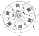
Fig. 1 is a schematic diagram of an entire structure of a device for monitoring swimming capability of fish in embodiments of the present invention. -
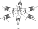
Fig. 2 is a schematic diagram of an assembling structure of a driving assembly and measuring channels in embodiments of the present invention. -
Fig. 3 is a partial enlarged diagram at the position A inFig. 2 . -
Fig. 4 is a schematic diagram of measuring channels and attachment structures in embodiments of the present invention. -
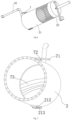
Fig. 5 is a schematic diagram of a fish expelling structure in embodiments of the present invention. - 1, monitoring shell; 11, monitoring barrel; 12, partition plate; 2, measuring channel; 21, fixed barrel; 211, water outlet holes; 212, outlet; 213, door body; 22, movable barrel; 221, first through hole; 222, second through hole; 223, second magnetic portion; 3, circulating pump assembly; 31, pump body; 32, water outlet pipe; 4, driving assembly; 41, rotation driving member; 42, connecting rod; 43, lifting barrel; 5, linear driving member; 6, mounting plate; 61, fish baiting structure; 62, first magnetic portion; 7, fish expelling structure; 71, floating plate; 72, moving rod; 73, flexible mat; and 8, turbulence flow generating mechanism.
- The technical solutions of the present disclosure will be clearly and completely described below in combination with the accompanying drawings, wherein the described embodiments are a part of the present invention. All other embodiments obtained by those of ordinary skill in the art based on the embodiments in the present disclosure without creative work belong to the scope of protection of the present invention defined by the appended claims.
- In the description of the present disclosure, it needs to be noted that directional or positional relations indicated by the terms "upper", "lower", "perpendicular", "horizontal" and the like are directional or positional relations shown based on the accompanying drawings, which are only for the convenience of describing the present disclosure and simplifying the description, rather than indicating or implying that the device or element referred to must have a specific orientation and be constructed and operated in a specific orientation, thus cannot be understood as a limitation of the present disclosure. In addition, the terms "first", "second" and "third" are only used for the purpose of description and cannot be understood as indicating or implying relative importance.
- In addition, the technical features involved in different implementations of the present disclosure described below can be combined with one another as long as they do not conflict with one another.
- A specific implementation of a device for monitoring swimming capability of fish as shown in
Fig. 1 includes: - a monitoring shell 1, including a
monitoring barrel 11 and a plurality ofpartition plates 12, wherein an opening of themonitoring barrel 11 is upward, the plurality ofpartition plates 12 are all located in themonitoring barrel 11 and evenly distributed in a circumferential direction of themonitoring barrel 11, thepartition plates 12 are strip-shaped plates, one end of each of the strip-shaped plates is connected to an inner wall of themonitoring barrel 11 in a sealed manner, the other end of each of the strip-shaped plates is connected to one another at a center of themonitoring barrel 11 in a sealed manner, and the plurality ofpartition plates 12 divide an inner cavity of themonitoring barrel 11 into a plurality of monitoring cavities evenly distributed in the circumferential direction; - a plurality of measuring
channels 2, corresponding to the monitoring cavities in a one-to-one manner, wherein the measuringchannels 2 are placed in the corresponding monitoring cavities during measuring, one end face of each of the measuringchannels 2 is provided with water outlet holes 211, testing spaces suitable for target fish activities are formed in the measuringchannels 2, and the measuringchannels 2 are of transparent structures or cage structures, so that fish swimming states inside the measuring channels are able to be observed from outside during monitoring; - a plurality of circulating pump assemblies 3, corresponding to the measuring
channels 2 in a one-to-one manner and each communicating with the other end face of each of thecorresponding measuring channels 2 during measuring, wherein the circulating pump assemblies 3 are configured to form streams in an extending direction of each of the measuringchannels 2; and - a driving assembly 4, connected with each measuring
channel 2 and configured to move all the measuringchannels 2 into respective adjacent monitoring cavities synchronously. - According to the device for monitoring swimming capability of fish, a plurality of different water environment conditions can be formed by controlling the flow rate in the measuring
channels 2 by the circulating pump assemblies 3, so that the swimming capability of the same species of fish under multiple different environments can be measured at the same time, there is no need to adjust the flow rate, and the monitoring efficiency is higher; and besides, different species of fishes can be placed in thedifferent measuring channels 2, then by sequentially placing fish in thesame measuring channel 2 into the different monitoring cavities, the swimming capability of the fishes under multiple different environments can be monitored at the same time, the fishes do not need to be taken out, only the action of the driving assembly 4 needs to be controlled, and the monitoring efficiency is higher. In addition, adjacent two of the measuringchannels 2 can be placed into the same monitoring cavity in sequence by the driving assembly 4, and then the swimming capability of the different species of fishes can be visually compared, so that two species of fishes requiring comparison can be placed in theadjacent measuring channels 2, which is more conductive to horizontal comparison of the swimming capability of different fishes. - It needs to be noted that the "barrel" above is a columnar shell structure with one end open and the other end closed.
- A specific shape of the
monitoring barrel 11 may be a cylinder shown inFig. 1 , or a polygonal barrel corresponding to a plurality of monitoring cavities, or a shape formed by replacing multiple edges of the polygonal barrel with a plurality of non-concyclic curves respectively. - An arrangement manner of the
partition plates 12 in themonitoring barrel 11 may be as shown inFig. 1 . The plate surfaces of thepartition plates 12 are perpendicular to the bottom of themonitoring barrel 11; alternatively, thepartition plates 12 may be disposed slantly relative to the bottom of themonitoring barrel 11, but are evenly distributed in the circumferential direction of themonitoring barrel 11, so that it is guaranteed that the orientation of each of thepartition plates 12 relative to the bottom of themonitoring barrel 11 is consistent; thepartition plates 12 are to divide the inner cavities of themonitoring barrel 11 into the plurality of monitoring cavities, so that thepartition plates 12 cannot be parallel to the bottom of the monitoring barrel; and apparently, the angles between thepartition plates 12 and the bottom of the monitoring barrel cannot be too small, otherwise the formed monitoring cavities are too low, and the amount of stored water cannot meet the demands of fish swimming. - The number of the
partition plates 12 may be 6 as inFig. 1 , or 8 or4 or the like, but is at least two. - The sealed connection of the
partition plates 12 on the inner wall of themonitoring barrel 11 may be in the manner of sealed adhesion, or the manner of sealing mats or the manner of welding or the like. - The other end of each of the strip-shaped plates is connected with one another at the center of the
monitoring barrel 11 in the sealed manner, and specifically, following solutions may be adopted: the first is that the other ends of all the strip-shaped plates are directly converged at the center of themonitoring barrel 11 and are connected with one another in a sealed manner; and the second is that as shown inFig. 1 , a stand column is fixed to the center of themonitoring barrel 11, and the other ends of all the strip-shaped plates are connected to the stand column in a sealed manner. It needs to be noted that the strip-shaped plates may be disposed in the radial direction or disposed relatively deviated from the radial direction. - It is easy to understand that the measuring
channels 2 are configured to provide spaces for fish swimming testing, so the measuringchannels 2 need to be able to form a relatively closed space, the so-called closed refers to that fish cannot swim out of the space at will rather than isolation from the outside, so as to guarantee the feasibility of testing. Specifically, as shown inFig. 1 , each of the measuringchannels 2 is composed of a cylinder and end plates at the two ends. Of course, a measuringchannel 2 adopting a square tube and end plates at the two ends or other cross-sectional shapes is also applicable. In addition, the measuringchannels 2 further need to be provided with access for placing in or taking out fish; and doors are configured at the access to guarantee that fish cannot swim out during testing. - It is easy to understand that the water outlet holes 211 are mainly disposed to provide outlets for streams so as to avoid the influence on the direction of the streams caused by returning of the streams. Specifically, at least one
water outlet hole 211 is disposed, but in practical operations, in order to reduce returning of the streams as much as possible, a section may be configured as a hollowed-out shape as shown inFig. 1 , and each hole in the hollowed-out shape is onewater outlet hole 211. - It needs to be understood that, in order to observe the swimming state of fish inside the measuring channels from the outside of the measuring
channels 2, the measuringchannels 2 need to be arranged into transparent structures or cage structures. Specifically, the measuringchannels 2 may be of fully-transparent structures or partially-transparent structures; and the cage structures may be mouse cage structures or hollowed-out structures or the like. - A preferred structure of each of the measuring
channels 2 is provided herein, referring toFig. 4 , including: - a fixed
barrel 21, with one end fixedly connected to the driving assembly 4; and - a
movable barrel 22, disposed coaxially with the fixedbarrel 21 and having one end telescopically connected to the other end of the fixedbarrel 21 by plug pin structures, wherein the plug pin structures include a plurality of groups evenly distributed in a circumferential direction of themovable barrel 22, and each interval between adjacent groups of plug pin structures is able to block fish from swimming out of the measuringchannel 2. - Each of the measuring
channels 2 includes the fixedbarrel 21 and themovable barrel 22, themovable barrel 22 can be driven to move relative to the fixedbarrel 21, and thus the measuringchannels 2 with different testing distances are formed to meet the requirements for monitoring the swimming capability of fishes different in body length and species. - The plug pin structures specifically include two solutions as follows: first, a plug pin is fixed to the end face of the fixed
barrel 21, a plug hole is formed in the corresponding end face of themovable barrel 22, and the plug pin is inserted into the plug hole; and second, as shown inFig. 4 , a plug hole is formed in the end face of the fixedbarrel 21, a plug pin is fixed to the corresponding end face of themovable barrel 22, and the plug pin is inserted into the plug hole. During specific arrangement, arrangement may be conducted according to a length relation between the fixedbarrel 21 and themovable barrel 22. As shown inFig. 4 , the length of the fixedbarrel 21 is greater than that of themovable barrel 22, so a plug hole is formed in the end face of the fixedbarrel 21 to guarantee that the plug hole can accommodate a large length of a plug pin, thereby increasing the telescopic range. - It needs to be understood that the fixed
barrel 21 needs to be connected to the driving assembly 4, because if themovable barrel 22 is connected with the driving assembly 4, the driving assembly 4 will move along with moving of themovable barrel 22, so that the structural design is more complex. - The specific positions of the circulating pump assemblies 3 are not limited, the circulating pump assemblies may be arranged at any end of each of the
corresponding measuring channels 2, but since the measuringchannels 2 are to rotate with arotation driving member 41, line connection of pumps with the outside is a technical problem, which may be solved by pumps with built-in batteries. - A preferred fixing manner of the circulating pump assemblies 3 is provided herein, as shown in
Fig. 1 andFig. 3 :
a plurality oflinear driving members 5 are evenly distributed on a wall of themonitoring barrel 11 in the circumferential direction, thelinear driving members 5 correspond to the monitoring cavities in a one-to-one manner, a mountingplate 6 is fixed to one end of a movable rod of each of thelinear driving members 5, each of the circulating pump assemblies 3 includes apump body 31 and awater outlet pipe 32, thepump body 31 is fixed to the mountingplate 6 and has a water inlet communicating with the corresponding monitoring cavity, thewater outlet pipe 32 communicates with a water outlet of thepump body 31, a first throughhole 221 is formed in an end face of the measuringchannel 2 close to the wall of themonitoring barrel 11, and thewater outlet pipe 32 has a first position where the water outlet pipe is inserted into the first throughhole 221 to spray water to the inside of the measuringchannel 2 and a second position where the water outlet pipe is separated from the first throughhole 221 to avoid a movement path of the measuringchannel 2. - The circulating pump assemblies 3 are mounted on the wall of the
monitoring barrel 11 through thelinear driving members 5, and compared with the solution of directly mounting the circulating pump assemblies 3 on the measuringchannels 2, the weight of the measuringchannels 2 is lowered, a transmission load of the driving assembly 4 is reduced, and the driving assembly 4 is smoother in operation. - The type of the
linear driving members 5 is not limited, and the linear driving members may be cylinders, hydraulic cylinders, linear motors, electric push rods, pneumatic push rods, hydraulic push rods or the like. Each of thelinear driving members 5 is composed of the movable rod and a shell. It needs to be noted that if the measuringchannels 2 adopt the aforementioned telescopic structures, thelinear driving members 5 need to adopt linear push rod structures, such as linear motors, electric push rods, pneumatic push rods or hydraulic push rods, because the length of movable rods of the linear push rods can be fixed to any length, and the circulating pump assemblies 3 can adapt to the measuringchannels 2 of different lengths. If the structures such as cylinders are adopted, since the cylinders only have a fixed telescopic amount and cannot stay at any position, the cylinders are not applicable to the aforementioned telescopic structures of the measuringchannels 2. - The mounting
plates 6 may be located inside themonitoring barrel 11 as shown inFig. 1 or outside themonitoring barrel 11, as long as thewater outlet pipes 32 penetrate through the wall of themonitoring barrel 11 in a sealed manner. The former is preferred, so that the outside structure of themonitoring barrel 11 is simpler, and the entire structural compactness is higher. - Further, as shown in
Fig. 3 , afish baiting structure 61 is further fixed to each of the mountingplates 6, thefish baiting structure 61 is disposed on the mountingplate 6 in a protruding manner towards a direction away from the corresponding linear drivingmember 5, a second throughhole 222 is formed in the end face of the measuringchannel 2 close to the wall of themonitoring barrel 11, thefish baiting structure 61 has a first position where the fish baiting structure is inserted into the second throughhole 222 and a second position where the fish baiting structure is separated from the second throughhole 222 to avoid a movement path of the measuringchannel 2, and the first position of thefish baiting structure 61 and the first position of thewater outlet pipe 32 are synchronously realized by action of the linear drivingmember 5. - The
fish baiting structures 61 can induce fish to swim to the positions of the fish baiting structures, thereby further improving the monitoring efficiency. - Specifically, the
fish baiting structures 61 may be ultrasonic generators, light sources, bait or the like. - Further, as shown in
Fig. 3 , a firstmagnetic portion 62 is further fixed to each of the mountingplates 6, a secondmagnetic portion 223 is fixed to the end face of the measuringchannel 2 close to the wall of themonitoring barrel 11, the firstmagnetic portion 62 has a first position where the first magnetic portion is attracted onto the secondmagnetic portion 223 during monitoring and a second position where the first magnetic portion is separated from the secondmagnetic portion 223, and the first position of the firstmagnetic portion 62 and the first position of thewater outlet pipe 32 are synchronously realized by action of the linear drivingmember 5. - The first
magnetic portions 62 and the secondmagnetic portions 223 are attracted during monitoring to make the measuringchannels 2 firmer, and interference on monitoring caused by external factors such as shaking of the measuringchannels 2 is avoided. - There are three solutions as follows for arrangement of the magnetic portions: first, the first
magnetic portions 62 are magnets and the secondmagnetic portions 223 are magnetic steel; second, the firstmagnetic portions 62 are magnetic steel and the secondmagnetic portions 223 are magnets; and third, both the firstmagnetic portions 62 and the secondmagnetic portions 223 are magnets and are opposite in polarity at joining surfaces. - The specific structure of the driving assembly 4 is not limited, as long as the driving assembly can complete two motions: first, the measuring
channels 2 can be driven to rotate in the circumferential direction of themonitoring barrel 11, and second, the measuringchannels 2 can be driven to move up to avoid the path where thepartition plates 12 enter the respective adjacent monitoring cavities. For example, the driving assembly 4 may be a combination of one rotation power member and a plurality of lifting power members, the plurality of lifting power members are evenly distributed on a rotating shaft of the rotation power member in a circumferential direction, the lifting power members drive the measuringchannels 2 to move up, and the rotation power member drives the measuringchannels 2 to rotate in the circumferential direction of themonitoring barrel 11. Specifically, the rotation power member is a motor, a rotating cylinder or the like, and the lifting power members are cylinders, synchronous belt assemblies or the like. - A preferred structure of the driving assembly 4 is provided herein, referring to
Fig. 2 , including: - a
rotation driving member 41, mounted at the center of themonitoring barrel 11, wherein a rotating shaft of therotation driving member 41 extends out of upper sides of thepartition plates 12 and is perpendicular to a bottom of themonitoring barrel 11; - a plurality of connecting
rods 42, corresponding to the plurality of measuringchannels 2 in a one-to-one manner, wherein one end of each of the connectingrods 42 is fixedly connected to one of the measuringchannels 2, and the other end of each of the connectingrods 42 is hinged to the rotating shaft and is able to rotate in a vertical plane; and - a lifting
barrel 43, fixed at the center of themonitoring barrel 11 and coaxial with the rotating shaft, wherein an upper end face of the liftingbarrel 43 is configured as a wavy curved surface, valleys of the wavy curved surface correspond to the plurality of measuringchannels 2 in a one-to-one manner, the connectingrods 42 rest on the wavy curved surface, and the wavy curved surface is configured to guide the measuringchannels 2 to move into the respective adjacent monitoring cavities when the rotating shaft rotates. - In the driving assembly 4, the measuring
channels 2 are controlled by therotation driving member 41 to rotate in the circumferential direction of themonitoring barrel 11, the liftingbarrel 43 is configured to avoid interference between the measuringchannels 2 and thepartition plates 12 during movement of the measuring channels, the structure is simple, operation is convenient, and the operation stability of all the measuringchannels 2 can be guaranteed. - Specifically, the
rotation driving member 41 may be a commonly used power mechanism that can output torque, such as a motor and a rotating cylinder. - Specifically, as shown in
Fig. 2 , the connectingrods 42 are Z-shaped rods, each Z-shaped rod includes a first rod, a second rod and a third rod perpendicularly connected to one another in sequence, each of the first rods rests on the wavy curved surface and has one end hinged to the rotating shaft, and one end of each of the third rods is fixedly connected to an end face, which is close to the center of themonitoring barrel 11, of one of the measuringchannels 2. Of course, the connectingrods 42 may be in a shape of a straight line or an L shape or other shapes, as long as the connecting rods can drive the measuringchannels 2 to move. - Further, as shown in
Fig. 5 , anoutlet 212 is formed in a lower portion of one end, which is close to the corresponding connectingrod 42, of each measuringchannel 2, theoutlet 212 is configured for fish in the measuringchannel 2 to swim out, adoor body 213 is mounted on theoutlet 212, and thedoor body 213 is provided with drain holes. Specifically, thedoor bodies 213 may be flip structures or sliding structures shown inFig. 5 . - When the connecting
rods 42 are located at peaks of the wavy curved surface, the end, which is close to the corresponding connectingrod 42, of each measuringchannel 2 is lower than the other end, water will gather at the end close to the connectingrod 42 and be discharged via the drain holes, at the moment, thedoor body 213 is opened, then a net bag is placed under theoutlet 212, fish will enter the net bag through theoutlet 212, and the fish is taken out. The operation is convenient, and the fish taking efficiency is improved. - According to an improved structure of the device for monitoring swimming capability of fish as shown in
Fig. 4 and Fig. 5 , a fish expelling structure 7 is disposed at one end of each of the measuringchannels 2 provided with the water outlet holes 211, the fish expelling structure 7 includes a floatingplate 71, a movingrod 72 and aflexible mat 73, an upper edge part of theflexible mat 73 is fixed to an inner wall of the measuringchannel 2, the movingrod 72 is slidably inserted into an upper barrel wall of the measuringchannel 2, a lower end of the movingrod 72 is fixedly connected to a lower edge part of theflexible mat 73, and an upper end of the movingrod 72 extends out of the measuringchannel 2 and is fixedly connected to the floatingplate 71. When the measuringchannels 2 enter the monitoring cavities, the floatingplates 71 are subjected to buoyancy and drive theflexible mats 73 to wrinkle by the movingrods 72, and thus fish is expelled to swim towards the side opposite to the water outlet holes 211, and the monitoring efficiency is further improved. - According to another improved structure of the device for monitoring swimming capability of fish as shown in
Fig. 1 , the device further includes a plurality of turbulenceflow generating mechanisms 8, and the plurality of turbulenceflow generating mechanisms 8 correspond to the monitoring cavities in a one-to-one manner and are mounted in the monitoring cavities. The turbulence flow performance, such as turbulence energy and a turbulence dissipation rate, in the corresponding monitoring cavities can be changed by the turbulenceflow generating mechanisms 8, and thus the swimming capability of fish under different turbulence flow performance can be monitored. - Based on the above implementations, a using method of the device for monitoring swimming capability of fish according to the present disclosure is as follows:
- (1) the length of each of the measuring
channels 2 is determined according to fish to be monitored, and themovable barrel 22 is moved to adjust the measuringchannel 2 to the target length; - (2) the
rotation driving member 41 is controlled to make the connectingrods 42 placed at the peaks of the wavy curved surface so as to place in fish from theoutlet 212 of the measuringchannel 2; - (3) the
rotation driving member 41 is controlled to make the connectingrods 42 placed at the valleys of the wavy curved surface, and each of the measuringchannels 2 is placed in the corresponding monitoring cavity; - (4) the
linear driving members 5 are controlled to make the secondmagnetic portions 223 and the firstmagnetic portions 62 attracted, meanwhile, thewater outlet pipes 32 of the circulating pump assemblies 3 are inserted into the first throughholes 221 of the measuringchannels 2, and thefish baiting structures 61 are inserted into the second throughholes 222 of the measuringchannels 2; - (5) a water environment condition of each of the monitoring cavities is set through the circulating pump assemblies 3 and the turbulence
flow generating mechanisms 8, and parameters such as time and swimming states of fish swimming from the fixedbarrel 21 to themovable barrel 22 are observed; - (6) the
rotation driving member 41 is controlled to make each of the measuringchannels 2 enter the next adjacent monitoring cavity, and parameters such as time and swimming states of fish swimming from the fixedbarrel 21 to themovable barrel 22 are observed; - (7) step (6) is repeated to monitor swimming situations of the fish under multiple different environments; and
- (8) according to steps (5)-(7), ranges of a water flow rate, turbulence energy, a turbulence dissipation rate, a strain rate and the like preferred by the fish are obtained via analysis, and then a response relationship of the fish for water flow under different water flow conditions is established.
- Apparently, the embodiments above are merely examples for clear description, rather than limitation to the implementations. For those of ordinary skill in the art, other changes or modifications of different forms can also be made on the basis of the above description. It is unnecessary and impossible to enumerate all embodiments here. The obvious changes or modifications arising therefrom are still within the protection scope of the present invention defined by the appended claims.
Claims (9)
- A device for monitoring swimming capability of fish, comprising:a monitoring shell (1), comprising a monitoring barrel (11) and a plurality of partition plates (12), wherein an opening of the monitoring barrel (11) is upward, the plurality of partition plates (12) are all located in the monitoring barrel (11) and evenly distributed in a circumferential direction of the monitoring barrel (11), the partition plates (12) are strip-shaped plates, one end of each of the strip-shaped plates is connected to an inner wall of the monitoring barrel (11) in a sealed manner, the other end of each of the strip-shaped plates is connected to one another at a center of the monitoring barrel (11) in a sealed manner, and the plurality of partition plates (12) divide an inner cavity of the monitoring barrel (11) into a plurality of monitoring cavities evenly distributed in the circumferential direction;a plurality of measuring channels (2), corresponding to the monitoring cavities in a one-to-one manner, wherein the measuring channels (2) are placed in the corresponding monitoring cavities during measuring, one end face of each of the measuring channels (2) is provided with water outlet holes (211), testing spaces suitable for target fish activities are formed in the measuring channels (2), and the measuring channels (2) are of transparent structures or cage structures, so that fish swimming states inside the measuring channels are able to be observed from outside during monitoring;a plurality of circulating pump assemblies (3), corresponding to the measuring channels (2) in a one-to-one manner and each communicating with the other end face of each of the corresponding measuring channels (2) during measuring, wherein the circulating pump assemblies (3) are configured to form streams in an extending direction of each of the measuring channels (2); anda driving assembly (4), connected with each measuring channel (2) and configured to move all the measuring channels (2) into respective adjacent monitoring cavities synchronously; whereinthe driving assembly (4) comprises:a rotation driving member (41), mounted at the center of the monitoring barrel (11), wherein a rotating shaft of the rotation driving member (41) extends out of upper sides of the partition plates (12) and is perpendicular to a bottom of the monitoring barrel (11);a plurality of connecting rods (42), corresponding to the plurality of measuring channels (2) in a one-to-one manner, wherein one end of each of the connecting rods (42) is fixedly connected to one of the measuring channels (2), and the other end of each of the connecting rods (42) is hinged to the rotating shaft and is able to rotate in a vertical plane; anda lifting barrel (43), fixed at the center of the monitoring barrel (11) and coaxial with the rotating shaft, wherein an upper end face of the lifting barrel (43) is configured as a wavy curved surface, valleys of the wavy curved surface correspond to the plurality of measuring channels (2) in a one-to-one manner, the connecting rods (42) rest on the wavy curved surface, and the wavy curved surface is configured to guide the measuring channels (2) to move into the respective adjacent monitoring cavities when the rotating shaft rotates.
- The device for monitoring swimming capability of fish according to claim 1, wherein the connecting rods (42) are Z-shaped rods, each Z-shaped rod comprises a first rod, a second rod and a third rod perpendicularly connected to one another in sequence, each of the first rods rests on the wavy curved surface and has one end hinged to the rotating shaft, and one end of each of the third rods is fixedly connected to an end face, which is close to the center of the monitoring barrel (11), of one of the measuring channels (2).
- The device for monitoring swimming capability of fish according to claim 1, wherein an outlet (212) is formed in a lower portion of one end, which is close to the corresponding connecting rod (42), of each measuring channel (2), the outlet (212) is configured for fish in the measuring channel (2) to swim out, a door body (213) is mounted on the outlet (212), and the door body (213) is provided with drain holes.
- The device for monitoring swimming capability of fish according to claim 1, wherein each of the measuring channels (2) comprises:a fixed barrel (21), with one end fixedly connected to the driving assembly (4); anda movable barrel (22), disposed coaxially with the fixed barrel (21) and having one end telescopically connected to the other end of the fixed barrel (21) by plug pin structures, wherein the plug pin structures comprise a plurality of groups evenly distributed in a circumferential direction of the movable barrel (22), and each interval between adjacent groups of plug pin structures is able to block fish from swimming out of the measuring channel (2).
- The device for monitoring swimming capability of fish according to claim 1, wherein a plurality of linear driving members (5) are evenly distributed on a wall of the monitoring barrel (11) in the circumferential direction, the linear driving members (5) correspond to the monitoring cavities in a one-to-one manner, a mounting plate (6) is fixed to one end of a movable rod of each of the linear driving members (5), each of the circulating pump assemblies (3) comprises a pump body (31) and a water outlet pipe (32), the pump body (31) is fixed to the mounting plate (6) and has a water inlet communicating with the corresponding monitoring cavity, the water outlet pipe (32) communicates with a water outlet of the pump body (31), a first through hole (221) is formed in an end face of the measuring channel (2) close to the wall of the monitoring barrel (11), and the water outlet pipe (32) has a first position where the water outlet pipe is inserted into the first through hole (221) to spray water to the inside of the measuring channel (2) and a second position where the water outlet pipe is separated from the first through hole (221) to avoid a movement path of the measuring channel (2).
- The device for monitoring swimming capability of fish according to claim 5, wherein a fish baiting structure (61) is further fixed to each of the mounting plates (6), the fish baiting structure (61) is disposed on the mounting plate (6) in a protruding manner towards a direction away from the corresponding linear driving member (5), a second through hole (222) is formed in the end face of the measuring channel (2) close to the wall of the monitoring barrel (11), the fish baiting structure (61) has a first position where the fish baiting structure is inserted into the second through hole (222) and a second position where the fish baiting structure is separated from the second through hole (222) to avoid a movement path of the measuring channel (2), and the first position of the fish baiting structure (61) and the first position of the water outlet pipe (32) are synchronously realized by action of the linear driving member (5).
- The device for monitoring swimming capability of fish according to claim 5, wherein a first magnetic portion (62) is further fixed to each of the mounting plates (6), a second magnetic portion (223) is fixed to the end face of the measuring channel (2) close to the wall of the monitoring barrel (11), the first magnetic portion (62) has a first position where the first magnetic portion is attracted onto the second magnetic portion (223) during monitoring and a second position where the first magnetic portion is separated from the second magnetic portion (223), and the first position of the first magnetic portion (62) and the first position of the water outlet pipe (32) are synchronously realized by action of the linear driving member (5).
- The device for monitoring swimming capability of fish according to claim 1, wherein a fish expelling structure (7) is disposed at one end of the measuring channel (2) provided with the water outlet holes (211), the fish expelling structure (7) comprises a floating plate (71), a moving rod (72) and a flexible mat (73), an upper edge part of the flexible mat (73) is fixed to an inner wall of the measuring channel (2), the moving rod (72) is slidably inserted into an upper barrel wall of the measuring channel (2), a lower end of the moving rods (72) is fixedly connected to a lower edge part of the flexible mat (73), and an upper end of the moving rod (72) extends out of the measuring channel (2) and is fixedly connected to the floating plate (71).
- The device for monitoring swimming capability of fish according to any one of claims 1-8, further comprising:
a plurality of turbulence flow generating mechanisms (8), corresponding to the monitoring cavities in a one-to-one manner and mounted in the monitoring cavities.
Applications Claiming Priority (1)
| Application Number | Priority Date | Filing Date | Title |
|---|---|---|---|
| CN202210701483.2A CN114766415B (en) | 2022-06-21 | 2022-06-21 | Fish swimming ability monitoring devices |
Publications (2)
| Publication Number | Publication Date |
|---|---|
| EP4295678A1 EP4295678A1 (en) | 2023-12-27 |
| EP4295678B1 true EP4295678B1 (en) | 2024-08-28 |
Family
ID=82421205
Family Applications (1)
| Application Number | Title | Priority Date | Filing Date |
|---|---|---|---|
| EP22207244.9A Active EP4295678B1 (en) | 2022-06-21 | 2022-11-14 | Device for monitoring swimming capability of fish |
Country Status (2)
| Country | Link |
|---|---|
| EP (1) | EP4295678B1 (en) |
| CN (1) | CN114766415B (en) |
Families Citing this family (1)
| Publication number | Priority date | Publication date | Assignee | Title |
|---|---|---|---|---|
| CN120615819B (en) * | 2025-07-21 | 2026-06-23 | 广东海洋大学 | Automatic monitoring and protecting device for ocean platform cultivation net cage with photovoltaic power generation function |
Family Cites Families (21)
| Publication number | Priority date | Publication date | Assignee | Title |
|---|---|---|---|---|
| JP3826211B2 (en) * | 1998-10-29 | 2006-09-27 | 上野 佳祐 | Live fish measuring device |
| CN103202254B (en) * | 2013-04-16 | 2015-03-11 | 中国水产科学研究院长江水产研究所 | Fish swimming capability measuring method and submerged open-type testing device |
| CN103858805B (en) * | 2014-03-28 | 2015-09-02 | 水利部中国科学院水工程生态研究所 | A kind of method and application assessing fish swimming capacity |
| CN104430076B (en) * | 2014-11-13 | 2020-12-25 | 水利部交通运输部国家能源局南京水利科学研究院 | Method for testing critical swimming speed of fish |
| CN106577377B (en) * | 2016-11-16 | 2019-03-01 | 水利部中国科学院水工程生态研究所 | A kind of design method of the fish pass structure water velocity based on fish swimming capacity |
| CN106818551B (en) * | 2017-01-09 | 2020-01-10 | 珠江水利委员会珠江水利科学研究院 | Testing device and method for researching selection of fish on external factors |
| CN107396875B (en) * | 2017-08-18 | 2022-10-25 | 华北水利水电大学 | Fish biomechanical property testing device and testing method thereof |
| CN107581134A (en) * | 2017-10-20 | 2018-01-16 | 上海海洋大学 | One kind automation fish swimming capacity test device and method |
| CN107646761A (en) * | 2017-11-08 | 2018-02-02 | 重庆师范大学 | A fish swimming ability measuring device |
| CN108277784B (en) * | 2018-02-05 | 2019-11-29 | 安徽理工大学 | It is adapted to the imitative nature fish pass of different Burden-Swimming Ability of KM fish |
| CN108040961A (en) * | 2018-02-05 | 2018-05-18 | 水利部交通运输部国家能源局南京水利科学研究院 | It is a kind of to test swimming pipe of the fish to dissolved gas tolerance degree |
| TWI669054B (en) * | 2018-11-08 | 2019-08-21 | 國立臺灣師範大學 | Device and method for analyzing rheotaxis performance of larval fish |
| CN109526814B (en) * | 2018-12-06 | 2024-11-29 | 中国长江三峡集团有限公司 | Structure for observing fish temporary rearing and swimming behavior and testing swimming capability |
| CN111449007A (en) * | 2020-05-12 | 2020-07-28 | 浙江省水利河口研究院 | Fish swimming capability testing device and method |
| CN212464554U (en) * | 2020-05-12 | 2021-02-05 | 浙江省水利河口研究院 | Fish swimming capability testing arrangement |
| CN212877218U (en) * | 2020-05-28 | 2021-04-06 | 水利部中国科学院水工程生态研究所 | A variable slope type fish swimming ability test tank |
| CN111642449B (en) * | 2020-05-28 | 2021-11-30 | 水利部中国科学院水工程生态研究所 | Slope-variable water tank for testing swimming capacity of fishes |
| CN111557270A (en) * | 2020-05-29 | 2020-08-21 | 中国科学院水生生物研究所 | Non-destructive testing device for testing fish habitat selection and application thereof |
| CN214015556U (en) * | 2020-11-05 | 2021-08-24 | 三峡大学 | Fish swimming capability test device |
| CN112482298B (en) * | 2020-12-08 | 2025-04-11 | 中国电建集团昆明勘测设计研究院有限公司 | A testing device and method for fishes passing through a dam in a mountain river |
| CN214194357U (en) * | 2020-12-08 | 2021-09-14 | 中国电建集团昆明勘测设计研究院有限公司 | Testing arrangement of mountain region river dam-crossing fish |
-
2022
- 2022-06-21 CN CN202210701483.2A patent/CN114766415B/en active Active
- 2022-11-14 EP EP22207244.9A patent/EP4295678B1/en active Active
Also Published As
| Publication number | Publication date |
|---|---|
| CN114766415A (en) | 2022-07-22 |
| CN114766415B (en) | 2022-09-06 |
| EP4295678A1 (en) | 2023-12-27 |
Similar Documents
| Publication | Publication Date | Title |
|---|---|---|
| CN118025416B (en) | A floating hydrological and water resources survey device | |
| EP4295678A1 (en) | Device for monitoring swimming capability of fish | |
| CN114475987A (en) | A multimodal mobile robot | |
| CN219200947U (en) | A dynamic acquisition device for land space ecological restoration information | |
| CN116929833A (en) | Marine geological environment exploration sampling equipment and sampling method | |
| CN118749480B (en) | A device for breaking nets and checking for leaks in deep-sea aquaculture cages | |
| CN211341168U (en) | Modular Building System | |
| CN220418857U (en) | A plant root soil collection device | |
| CN117309318A (en) | Integrated circulating water tank simulating wave flow environment | |
| CN216104271U (en) | Water drainage device and water drainage assembly | |
| CN114753971A (en) | Reinforced support frame structure of cylindrical foundation subdivision plate | |
| CN209711069U (en) | A kind of scale sheep raising | |
| CN220583831U (en) | Water quality sampler | |
| CN224262586U (en) | Mounting structure of time difference ultrasonic open channel flowmeter | |
| CN118225484A (en) | Soft coring device for coring in cement soil | |
| CN110193224A (en) | A kind of environmental monitoring laboratory water sample pretreatment rapid filtration device | |
| CN222065762U (en) | Corrosion-resistant net rack sealing plate | |
| CN223269743U (en) | Site isolation fence for constructional engineering | |
| CN222673786U (en) | Electric power protection tube convenient to change | |
| CN222070229U (en) | River sediment sampling device in high water period | |
| CN223976828U (en) | Deep and shallow pool baffle structure and test pool | |
| CN112385617A (en) | Automatic fish attracting and driving system | |
| CN222145001U (en) | Buoy type water quality monitoring device | |
| CN222529333U (en) | A monitoring device for water environment | |
| CN215811797U (en) | Geological disaster prevention, control, monitoring and sampling device |
Legal Events
| Date | Code | Title | Description |
|---|---|---|---|
| PUAI | Public reference made under article 153(3) epc to a published international application that has entered the european phase |
Free format text: ORIGINAL CODE: 0009012 |
|
| STAA | Information on the status of an ep patent application or granted ep patent |
Free format text: STATUS: REQUEST FOR EXAMINATION WAS MADE |
|
| 17P | Request for examination filed |
Effective date: 20221114 |
|
| AK | Designated contracting states |
Kind code of ref document: A1 Designated state(s): AL AT BE BG CH CY CZ DE DK EE ES FI FR GB GR HR HU IE IS IT LI LT LU LV MC ME MK MT NL NO PL PT RO RS SE SI SK SM TR |
|
| GRAP | Despatch of communication of intention to grant a patent |
Free format text: ORIGINAL CODE: EPIDOSNIGR1 |
|
| STAA | Information on the status of an ep patent application or granted ep patent |
Free format text: STATUS: GRANT OF PATENT IS INTENDED |
|
| INTG | Intention to grant announced |
Effective date: 20240412 |
|
| GRAS | Grant fee paid |
Free format text: ORIGINAL CODE: EPIDOSNIGR3 |
|
| GRAA | (expected) grant |
Free format text: ORIGINAL CODE: 0009210 |
|
| STAA | Information on the status of an ep patent application or granted ep patent |
Free format text: STATUS: THE PATENT HAS BEEN GRANTED |
|
| AK | Designated contracting states |
Kind code of ref document: B1 Designated state(s): AL AT BE BG CH CY CZ DE DK EE ES FI FR GB GR HR HU IE IS IT LI LT LU LV MC ME MK MT NL NO PL PT RO RS SE SI SK SM TR |
|
| REG | Reference to a national code |
Ref country code: CH Ref legal event code: EP |
|
| REG | Reference to a national code |
Ref country code: DE Ref legal event code: R096 Ref document number: 602022005684 Country of ref document: DE |
|
| REG | Reference to a national code |
Ref country code: IE Ref legal event code: FG4D |
|
| REG | Reference to a national code |
Ref country code: LT Ref legal event code: MG9D |
|
| PG25 | Lapsed in a contracting state [announced via postgrant information from national office to epo] |
Ref country code: NO Free format text: LAPSE BECAUSE OF FAILURE TO SUBMIT A TRANSLATION OF THE DESCRIPTION OR TO PAY THE FEE WITHIN THE PRESCRIBED TIME-LIMIT Effective date: 20241128 |
|
| REG | Reference to a national code |
Ref country code: AT Ref legal event code: MK05 Ref document number: 1716925 Country of ref document: AT Kind code of ref document: T Effective date: 20240828 |
|
| PG25 | Lapsed in a contracting state [announced via postgrant information from national office to epo] |
Ref country code: PL Free format text: LAPSE BECAUSE OF FAILURE TO SUBMIT A TRANSLATION OF THE DESCRIPTION OR TO PAY THE FEE WITHIN THE PRESCRIBED TIME-LIMIT Effective date: 20240828 Ref country code: NL Free format text: LAPSE BECAUSE OF FAILURE TO SUBMIT A TRANSLATION OF THE DESCRIPTION OR TO PAY THE FEE WITHIN THE PRESCRIBED TIME-LIMIT Effective date: 20240828 Ref country code: GR Free format text: LAPSE BECAUSE OF FAILURE TO SUBMIT A TRANSLATION OF THE DESCRIPTION OR TO PAY THE FEE WITHIN THE PRESCRIBED TIME-LIMIT Effective date: 20241129 Ref country code: FI Free format text: LAPSE BECAUSE OF FAILURE TO SUBMIT A TRANSLATION OF THE DESCRIPTION OR TO PAY THE FEE WITHIN THE PRESCRIBED TIME-LIMIT Effective date: 20240828 Ref country code: PT Free format text: LAPSE BECAUSE OF FAILURE TO SUBMIT A TRANSLATION OF THE DESCRIPTION OR TO PAY THE FEE WITHIN THE PRESCRIBED TIME-LIMIT Effective date: 20241230 |
|
| PG25 | Lapsed in a contracting state [announced via postgrant information from national office to epo] |
Ref country code: BG Free format text: LAPSE BECAUSE OF FAILURE TO SUBMIT A TRANSLATION OF THE DESCRIPTION OR TO PAY THE FEE WITHIN THE PRESCRIBED TIME-LIMIT Effective date: 20240828 |
|
| PG25 | Lapsed in a contracting state [announced via postgrant information from national office to epo] |
Ref country code: LV Free format text: LAPSE BECAUSE OF FAILURE TO SUBMIT A TRANSLATION OF THE DESCRIPTION OR TO PAY THE FEE WITHIN THE PRESCRIBED TIME-LIMIT Effective date: 20240828 |
|
| REG | Reference to a national code |
Ref country code: NL Ref legal event code: MP Effective date: 20240828 |
|
| PG25 | Lapsed in a contracting state [announced via postgrant information from national office to epo] |
Ref country code: AT Free format text: LAPSE BECAUSE OF FAILURE TO SUBMIT A TRANSLATION OF THE DESCRIPTION OR TO PAY THE FEE WITHIN THE PRESCRIBED TIME-LIMIT Effective date: 20240828 Ref country code: IS Free format text: LAPSE BECAUSE OF FAILURE TO SUBMIT A TRANSLATION OF THE DESCRIPTION OR TO PAY THE FEE WITHIN THE PRESCRIBED TIME-LIMIT Effective date: 20241228 |
|
| PG25 | Lapsed in a contracting state [announced via postgrant information from national office to epo] |
Ref country code: HR Free format text: LAPSE BECAUSE OF FAILURE TO SUBMIT A TRANSLATION OF THE DESCRIPTION OR TO PAY THE FEE WITHIN THE PRESCRIBED TIME-LIMIT Effective date: 20240828 |
|
| PG25 | Lapsed in a contracting state [announced via postgrant information from national office to epo] |
Ref country code: RS Free format text: LAPSE BECAUSE OF FAILURE TO SUBMIT A TRANSLATION OF THE DESCRIPTION OR TO PAY THE FEE WITHIN THE PRESCRIBED TIME-LIMIT Effective date: 20241128 Ref country code: ES Free format text: LAPSE BECAUSE OF FAILURE TO SUBMIT A TRANSLATION OF THE DESCRIPTION OR TO PAY THE FEE WITHIN THE PRESCRIBED TIME-LIMIT Effective date: 20240828 |
|
| PG25 | Lapsed in a contracting state [announced via postgrant information from national office to epo] |
Ref country code: RS Free format text: LAPSE BECAUSE OF FAILURE TO SUBMIT A TRANSLATION OF THE DESCRIPTION OR TO PAY THE FEE WITHIN THE PRESCRIBED TIME-LIMIT Effective date: 20241128 Ref country code: PT Free format text: LAPSE BECAUSE OF FAILURE TO SUBMIT A TRANSLATION OF THE DESCRIPTION OR TO PAY THE FEE WITHIN THE PRESCRIBED TIME-LIMIT Effective date: 20241230 Ref country code: PL Free format text: LAPSE BECAUSE OF FAILURE TO SUBMIT A TRANSLATION OF THE DESCRIPTION OR TO PAY THE FEE WITHIN THE PRESCRIBED TIME-LIMIT Effective date: 20240828 Ref country code: NO Free format text: LAPSE BECAUSE OF FAILURE TO SUBMIT A TRANSLATION OF THE DESCRIPTION OR TO PAY THE FEE WITHIN THE PRESCRIBED TIME-LIMIT Effective date: 20241128 Ref country code: NL Free format text: LAPSE BECAUSE OF FAILURE TO SUBMIT A TRANSLATION OF THE DESCRIPTION OR TO PAY THE FEE WITHIN THE PRESCRIBED TIME-LIMIT Effective date: 20240828 Ref country code: LV Free format text: LAPSE BECAUSE OF FAILURE TO SUBMIT A TRANSLATION OF THE DESCRIPTION OR TO PAY THE FEE WITHIN THE PRESCRIBED TIME-LIMIT Effective date: 20240828 Ref country code: IS Free format text: LAPSE BECAUSE OF FAILURE TO SUBMIT A TRANSLATION OF THE DESCRIPTION OR TO PAY THE FEE WITHIN THE PRESCRIBED TIME-LIMIT Effective date: 20241228 Ref country code: HR Free format text: LAPSE BECAUSE OF FAILURE TO SUBMIT A TRANSLATION OF THE DESCRIPTION OR TO PAY THE FEE WITHIN THE PRESCRIBED TIME-LIMIT Effective date: 20240828 Ref country code: GR Free format text: LAPSE BECAUSE OF FAILURE TO SUBMIT A TRANSLATION OF THE DESCRIPTION OR TO PAY THE FEE WITHIN THE PRESCRIBED TIME-LIMIT Effective date: 20241129 Ref country code: FI Free format text: LAPSE BECAUSE OF FAILURE TO SUBMIT A TRANSLATION OF THE DESCRIPTION OR TO PAY THE FEE WITHIN THE PRESCRIBED TIME-LIMIT Effective date: 20240828 Ref country code: ES Free format text: LAPSE BECAUSE OF FAILURE TO SUBMIT A TRANSLATION OF THE DESCRIPTION OR TO PAY THE FEE WITHIN THE PRESCRIBED TIME-LIMIT Effective date: 20240828 Ref country code: BG Free format text: LAPSE BECAUSE OF FAILURE TO SUBMIT A TRANSLATION OF THE DESCRIPTION OR TO PAY THE FEE WITHIN THE PRESCRIBED TIME-LIMIT Effective date: 20240828 Ref country code: AT Free format text: LAPSE BECAUSE OF FAILURE TO SUBMIT A TRANSLATION OF THE DESCRIPTION OR TO PAY THE FEE WITHIN THE PRESCRIBED TIME-LIMIT Effective date: 20240828 |
|
| PG25 | Lapsed in a contracting state [announced via postgrant information from national office to epo] |
Ref country code: RO Free format text: LAPSE BECAUSE OF FAILURE TO SUBMIT A TRANSLATION OF THE DESCRIPTION OR TO PAY THE FEE WITHIN THE PRESCRIBED TIME-LIMIT Effective date: 20240828 Ref country code: SM Free format text: LAPSE BECAUSE OF FAILURE TO SUBMIT A TRANSLATION OF THE DESCRIPTION OR TO PAY THE FEE WITHIN THE PRESCRIBED TIME-LIMIT Effective date: 20240828 Ref country code: DK Free format text: LAPSE BECAUSE OF FAILURE TO SUBMIT A TRANSLATION OF THE DESCRIPTION OR TO PAY THE FEE WITHIN THE PRESCRIBED TIME-LIMIT Effective date: 20240828 |
|
| PG25 | Lapsed in a contracting state [announced via postgrant information from national office to epo] |
Ref country code: EE Free format text: LAPSE BECAUSE OF FAILURE TO SUBMIT A TRANSLATION OF THE DESCRIPTION OR TO PAY THE FEE WITHIN THE PRESCRIBED TIME-LIMIT Effective date: 20240828 |
|
| PG25 | Lapsed in a contracting state [announced via postgrant information from national office to epo] |
Ref country code: CZ Free format text: LAPSE BECAUSE OF FAILURE TO SUBMIT A TRANSLATION OF THE DESCRIPTION OR TO PAY THE FEE WITHIN THE PRESCRIBED TIME-LIMIT Effective date: 20240828 |
|
| PG25 | Lapsed in a contracting state [announced via postgrant information from national office to epo] |
Ref country code: SK Free format text: LAPSE BECAUSE OF FAILURE TO SUBMIT A TRANSLATION OF THE DESCRIPTION OR TO PAY THE FEE WITHIN THE PRESCRIBED TIME-LIMIT Effective date: 20240828 Ref country code: IT Free format text: LAPSE BECAUSE OF FAILURE TO SUBMIT A TRANSLATION OF THE DESCRIPTION OR TO PAY THE FEE WITHIN THE PRESCRIBED TIME-LIMIT Effective date: 20240828 |
|
| REG | Reference to a national code |
Ref country code: DE Ref legal event code: R097 Ref document number: 602022005684 Country of ref document: DE |
|
| REG | Reference to a national code |
Ref country code: DE Ref legal event code: R119 Ref document number: 602022005684 Country of ref document: DE |
|
| PLBE | No opposition filed within time limit |
Free format text: ORIGINAL CODE: 0009261 |
|
| STAA | Information on the status of an ep patent application or granted ep patent |
Free format text: STATUS: NO OPPOSITION FILED WITHIN TIME LIMIT |
|
| PG25 | Lapsed in a contracting state [announced via postgrant information from national office to epo] |
Ref country code: MC Free format text: LAPSE BECAUSE OF FAILURE TO SUBMIT A TRANSLATION OF THE DESCRIPTION OR TO PAY THE FEE WITHIN THE PRESCRIBED TIME-LIMIT Effective date: 20240828 |
|
| PG25 | Lapsed in a contracting state [announced via postgrant information from national office to epo] |
Ref country code: LU Free format text: LAPSE BECAUSE OF NON-PAYMENT OF DUE FEES Effective date: 20241114 |
|
| 26N | No opposition filed |
Effective date: 20250530 |
|
| REG | Reference to a national code |
Ref country code: BE Ref legal event code: MM Effective date: 20241130 |
|
| PG25 | Lapsed in a contracting state [announced via postgrant information from national office to epo] |
Ref country code: SE Free format text: LAPSE BECAUSE OF FAILURE TO SUBMIT A TRANSLATION OF THE DESCRIPTION OR TO PAY THE FEE WITHIN THE PRESCRIBED TIME-LIMIT Effective date: 20240828 |
|
| PG25 | Lapsed in a contracting state [announced via postgrant information from national office to epo] |
Ref country code: DE Free format text: LAPSE BECAUSE OF NON-PAYMENT OF DUE FEES Effective date: 20250603 |
|
| PG25 | Lapsed in a contracting state [announced via postgrant information from national office to epo] |
Ref country code: BE Free format text: LAPSE BECAUSE OF NON-PAYMENT OF DUE FEES Effective date: 20241130 |
|
| PG25 | Lapsed in a contracting state [announced via postgrant information from national office to epo] |
Ref country code: FR Free format text: LAPSE BECAUSE OF NON-PAYMENT OF DUE FEES Effective date: 20241130 |
|
| PG25 | Lapsed in a contracting state [announced via postgrant information from national office to epo] |
Ref country code: IE Free format text: LAPSE BECAUSE OF NON-PAYMENT OF DUE FEES Effective date: 20241114 |
|
| PG25 | Lapsed in a contracting state [announced via postgrant information from national office to epo] |
Ref country code: HU Free format text: LAPSE BECAUSE OF FAILURE TO SUBMIT A TRANSLATION OF THE DESCRIPTION OR TO PAY THE FEE WITHIN THE PRESCRIBED TIME-LIMIT; INVALID AB INITIO Effective date: 20221114 |
|
| PG25 | Lapsed in a contracting state [announced via postgrant information from national office to epo] |
Ref country code: CY Free format text: LAPSE BECAUSE OF FAILURE TO SUBMIT A TRANSLATION OF THE DESCRIPTION OR TO PAY THE FEE WITHIN THE PRESCRIBED TIME-LIMIT; INVALID AB INITIO Effective date: 20221114 |
|
| PG25 | Lapsed in a contracting state [announced via postgrant information from national office to epo] |
Ref country code: TR Free format text: LAPSE BECAUSE OF FAILURE TO SUBMIT A TRANSLATION OF THE DESCRIPTION OR TO PAY THE FEE WITHIN THE PRESCRIBED TIME-LIMIT Effective date: 20240828 |
|
| PG25 | Lapsed in a contracting state [announced via postgrant information from national office to epo] |
Ref country code: SI Free format text: LAPSE BECAUSE OF FAILURE TO SUBMIT A TRANSLATION OF THE DESCRIPTION OR TO PAY THE FEE WITHIN THE PRESCRIBED TIME-LIMIT Effective date: 20240828 |
|
| REG | Reference to a national code |
Ref country code: CH Ref legal event code: H13 Free format text: ST27 STATUS EVENT CODE: U-0-0-H10-H13 (AS PROVIDED BY THE NATIONAL OFFICE) Effective date: 20260623 |
|
| PG25 | Lapsed in a contracting state [announced via postgrant information from national office to epo] |
Ref country code: LT Free format text: LAPSE BECAUSE OF FAILURE TO SUBMIT A TRANSLATION OF THE DESCRIPTION OR TO PAY THE FEE WITHIN THE PRESCRIBED TIME-LIMIT Effective date: 20240828 |
|
| PG25 | Lapsed in a contracting state [announced via postgrant information from national office to epo] |
Ref country code: ME Free format text: LAPSE BECAUSE OF FAILURE TO SUBMIT A TRANSLATION OF THE DESCRIPTION OR TO PAY THE FEE WITHIN THE PRESCRIBED TIME-LIMIT Effective date: 20240828 |
|
| PG25 | Lapsed in a contracting state [announced via postgrant information from national office to epo] |
Ref country code: CH Free format text: LAPSE BECAUSE OF NON-PAYMENT OF DUE FEES Effective date: 20251130 |