EP4295063B1 - Pneumatic standstill shaft seal - Google Patents
Pneumatic standstill shaft seal Download PDFInfo
- Publication number
- EP4295063B1 EP4295063B1 EP23734440.3A EP23734440A EP4295063B1 EP 4295063 B1 EP4295063 B1 EP 4295063B1 EP 23734440 A EP23734440 A EP 23734440A EP 4295063 B1 EP4295063 B1 EP 4295063B1
- Authority
- EP
- European Patent Office
- Prior art keywords
- flexible band
- central region
- shaft
- seal
- standstill seal
- Prior art date
- Legal status (The legal status is an assumption and is not a legal conclusion. Google has not performed a legal analysis and makes no representation as to the accuracy of the status listed.)
- Active
Links
Images







Classifications
-
- F—MECHANICAL ENGINEERING; LIGHTING; HEATING; WEAPONS; BLASTING
- F16—ENGINEERING ELEMENTS AND UNITS; GENERAL MEASURES FOR PRODUCING AND MAINTAINING EFFECTIVE FUNCTIONING OF MACHINES OR INSTALLATIONS; THERMAL INSULATION IN GENERAL
- F16J—PISTONS; CYLINDERS; SEALINGS
- F16J15/00—Sealings
- F16J15/002—Sealings comprising at least two sealings in succession
- F16J15/008—Sealings comprising at least two sealings in succession with provision to put out of action at least one sealing; One sealing sealing only on standstill; Emergency or servicing sealings
-
- F—MECHANICAL ENGINEERING; LIGHTING; HEATING; WEAPONS; BLASTING
- F16—ENGINEERING ELEMENTS AND UNITS; GENERAL MEASURES FOR PRODUCING AND MAINTAINING EFFECTIVE FUNCTIONING OF MACHINES OR INSTALLATIONS; THERMAL INSULATION IN GENERAL
- F16J—PISTONS; CYLINDERS; SEALINGS
- F16J15/00—Sealings
- F16J15/02—Sealings between relatively-stationary surfaces
- F16J15/021—Sealings between relatively-stationary surfaces with elastic packing
- F16J15/028—Sealings between relatively-stationary surfaces with elastic packing the packing being mechanically expanded against the sealing surface
-
- F—MECHANICAL ENGINEERING; LIGHTING; HEATING; WEAPONS; BLASTING
- F16—ENGINEERING ELEMENTS AND UNITS; GENERAL MEASURES FOR PRODUCING AND MAINTAINING EFFECTIVE FUNCTIONING OF MACHINES OR INSTALLATIONS; THERMAL INSULATION IN GENERAL
- F16J—PISTONS; CYLINDERS; SEALINGS
- F16J15/00—Sealings
- F16J15/02—Sealings between relatively-stationary surfaces
- F16J15/06—Sealings between relatively-stationary surfaces with solid packing compressed between sealing surfaces
- F16J15/10—Sealings between relatively-stationary surfaces with solid packing compressed between sealing surfaces with non-metallic packing
- F16J15/104—Sealings between relatively-stationary surfaces with solid packing compressed between sealing surfaces with non-metallic packing characterised by structure
-
- F—MECHANICAL ENGINEERING; LIGHTING; HEATING; WEAPONS; BLASTING
- F16—ENGINEERING ELEMENTS AND UNITS; GENERAL MEASURES FOR PRODUCING AND MAINTAINING EFFECTIVE FUNCTIONING OF MACHINES OR INSTALLATIONS; THERMAL INSULATION IN GENERAL
- F16J—PISTONS; CYLINDERS; SEALINGS
- F16J15/00—Sealings
- F16J15/16—Sealings between relatively-moving surfaces
- F16J15/18—Sealings between relatively-moving surfaces with stuffing-boxes for elastic or plastic packings
- F16J15/184—Tightening mechanisms
- F16J15/185—Tightening mechanisms with continuous adjustment of the compression of the packing
- F16J15/186—Tightening mechanisms with continuous adjustment of the compression of the packing using springs
-
- F—MECHANICAL ENGINEERING; LIGHTING; HEATING; WEAPONS; BLASTING
- F16—ENGINEERING ELEMENTS AND UNITS; GENERAL MEASURES FOR PRODUCING AND MAINTAINING EFFECTIVE FUNCTIONING OF MACHINES OR INSTALLATIONS; THERMAL INSULATION IN GENERAL
- F16J—PISTONS; CYLINDERS; SEALINGS
- F16J15/00—Sealings
- F16J15/16—Sealings between relatively-moving surfaces
- F16J15/32—Sealings between relatively-moving surfaces with elastic sealings, e.g. O-rings
- F16J15/3204—Sealings between relatively-moving surfaces with elastic sealings, e.g. O-rings with at least one lip
- F16J15/3208—Sealings between relatively-moving surfaces with elastic sealings, e.g. O-rings with at least one lip provided with tension elements, e.g. elastic rings
- F16J15/3212—Sealings between relatively-moving surfaces with elastic sealings, e.g. O-rings with at least one lip provided with tension elements, e.g. elastic rings with metal springs
-
- F—MECHANICAL ENGINEERING; LIGHTING; HEATING; WEAPONS; BLASTING
- F16—ENGINEERING ELEMENTS AND UNITS; GENERAL MEASURES FOR PRODUCING AND MAINTAINING EFFECTIVE FUNCTIONING OF MACHINES OR INSTALLATIONS; THERMAL INSULATION IN GENERAL
- F16J—PISTONS; CYLINDERS; SEALINGS
- F16J15/00—Sealings
- F16J15/16—Sealings between relatively-moving surfaces
- F16J15/32—Sealings between relatively-moving surfaces with elastic sealings, e.g. O-rings
- F16J15/3204—Sealings between relatively-moving surfaces with elastic sealings, e.g. O-rings with at least one lip
- F16J15/322—Sealings between relatively-moving surfaces with elastic sealings, e.g. O-rings with at least one lip supported in a direction perpendicular to the surfaces
-
- F—MECHANICAL ENGINEERING; LIGHTING; HEATING; WEAPONS; BLASTING
- F16—ENGINEERING ELEMENTS AND UNITS; GENERAL MEASURES FOR PRODUCING AND MAINTAINING EFFECTIVE FUNCTIONING OF MACHINES OR INSTALLATIONS; THERMAL INSULATION IN GENERAL
- F16J—PISTONS; CYLINDERS; SEALINGS
- F16J15/00—Sealings
- F16J15/16—Sealings between relatively-moving surfaces
- F16J15/34—Sealings between relatively-moving surfaces with slip-ring pressed against a more or less radial face on one member
- F16J15/3436—Pressing means
- F16J15/3448—Pressing means the pressing force resulting from fluid pressure
-
- F—MECHANICAL ENGINEERING; LIGHTING; HEATING; WEAPONS; BLASTING
- F16—ENGINEERING ELEMENTS AND UNITS; GENERAL MEASURES FOR PRODUCING AND MAINTAINING EFFECTIVE FUNCTIONING OF MACHINES OR INSTALLATIONS; THERMAL INSULATION IN GENERAL
- F16J—PISTONS; CYLINDERS; SEALINGS
- F16J15/00—Sealings
- F16J15/16—Sealings between relatively-moving surfaces
- F16J15/34—Sealings between relatively-moving surfaces with slip-ring pressed against a more or less radial face on one member
- F16J15/38—Sealings between relatively-moving surfaces with slip-ring pressed against a more or less radial face on one member sealed by a packing
-
- F—MECHANICAL ENGINEERING; LIGHTING; HEATING; WEAPONS; BLASTING
- F16—ENGINEERING ELEMENTS AND UNITS; GENERAL MEASURES FOR PRODUCING AND MAINTAINING EFFECTIVE FUNCTIONING OF MACHINES OR INSTALLATIONS; THERMAL INSULATION IN GENERAL
- F16J—PISTONS; CYLINDERS; SEALINGS
- F16J15/00—Sealings
- F16J15/46—Sealings with packing ring expanded or pressed into place by fluid pressure, e.g. inflatable packings
Definitions
- the invention relates to standstill seals, and more particularly, to pressure-driven standstill seals that are applicable for sealing against high pressure differentials.
- one approach is to provide a solid, rigid sealing annulus 100 that surrounds the shaft 102 and can be pressed axially into contact with a radial structure 104 that is sealed to the shaft 102 via a supporting structure 106.
- the sealing annulus 100 is pneumatically driven against the radial structure 104 when the shaft 102 is not rotating, and is withdrawn from the shaft 102 by a spring 108 when the shaft is rotating.
- the sealing annulus 100 is driven by a bi-directional pneumatic piston or by mechanical mechanism such as a solenoid.
- the standstill shaft seal is activated and deactivated by a controller (not shown), which may be but is not necessarily the same controller that also controls the rotational starting and stopping of the shaft.
- FIG. 1B illustrates the standstill shaft seal when it is open
- Fig. 1C illustrates the seal when it is closed.
- Figs. 1B and 1C The approach of Figs. 1B and 1C is simple, and relatively easy to manufacture. However, it can be difficult to provide complex cross-sectional shaping to the tube 110, because it is typically extruded rather than cast.
- a shaped elastomeric band 118 is snapped onto a supporting form 120 and installed within the housing 112.
- the supporting form 120 is penetrated by the inflation inlet 116, which is directed to a rear surface of the band 118.
- the elastomeric band 118 remains flat against the supporting form 120, and does not extend beyond the housing 112.
- Fig. 1D when no pressure is applied via the inflation inlet 116, the elastomeric band 118 remains flat against the supporting form 120, and does not extend beyond the housing 112.
- Document US 3 985 365 A discloses a remotely actuated emergency shaft seal.
- Document US 3 578 342 A discloses a shaft seal.
- Document US 4 342 336 A discloses a double-acting inflatable seal.
- Document JP H06 344984 A discloses a bulkhead sealing device for ship.
- the present invention is a fluid pressure driven standstill shaft seal according to appended claims that is simple in design, relatively low cost to produce, and able to form a seal that reliably withstands high pressure process fluids, such as process gasses pressurized to 70 Bar or higher.
- the disclosed seal comprises a flexible band that is installed within an annular housing and surrounds a rotatable shaft.
- the flexible band comprises a thick, substantially rectangular central region flanked by thinner side regions on either side thereof.
- the thinner side regions of the flexible band provide radial or axial flexibility to the central region, such that the thick central region is able to be extended through an annular opening in the housing and then retracted therefrom.
- the thickness of the central region enables it to resist being distorted or extruded when it is pressed against the shaft and subject to a high fluid pressure differential. Pressurized control fluid is applied behind the central region via a control fluid inlet to close the standstill seal.
- the pressurized control fluid that is applied behind the flexible band is controlled by a controller, which in embodiments also controls the rotation of the shaft. While the shaft is rotating, no pressure is applied behind the central region of the flexible band, such that it remains partially or fully within the annular housing and does not contact the shaft. When the shaft is not rotating (i.e. is in a standstill condition), fluid pressure is applied by the controller behind the central region of the flexible band via the control fluid inlet. As a result, the central region of the flexible band is pushed through the annular opening in the housing, and is pressed against the shaft, or against an intermediate structure that is sealed to the shaft, forming a standstill seal therewith.
- the change in diameter of the central region is only a small percentage of the full diameter of the flexible band, such that the central region is easily able to accommodate the circumferential compression that is required as the central region is pressed radially inward toward the shaft.
- the source of the control fluid is independent of the process, and can be, for example, a source of pressurized nitrogen gas, pressurized air, or a pressurized liquid.
- the control fluid is the process fluid.
- a pressure boosting device is used to increase the pressure of the process fluid that is applied behind the flexible band.
- Some of these embodiments include a pair of annular, toothed springs, each of which has a solid annular region that is clamped in place within the housing, and a toothed annular region that is beneath at least a portion of the side regions of the flexible band.
- the toothed springs provide added return force that ensures full withdrawal of the central region from the shaft.
- Embodiments further include a pair of rigid annular rings on either side of the thick central region which completely eliminate the possibility that any of the thick region might be extruded into the gap between the housing and the shaft when the standstill seal is engaged.
- the annular rings can be attached to the central region of the flexible band or they can be fixed to the housing and extend into the gap between the shaft and the housing.
- the standstill seal of the present invention can be implemented together with at least one rotating shaft seal, such as a rotating face mechanical seal.
- the standstill seal can be implemented upstream or downstream of the rotating shaft seal. Or, if a plurality of rotating shaft seals are included, then the standstill seal can be implemented between the rotating shaft seals. In some embodiments, a plurality of the disclosed standstill seals are deployed, for example one upstream of the rotating shaft seal and one downstream of the rotating shaft seal.
- the standstill seal is configured, when the controller applies the pressurized control fluid to the control fluid inlet, to extend the central region of the flexible band through the gap such that it makes contact and forms a seal with the shaft, or with an intermediate structure that is sealed to the shaft.
- the standstill seal is also configured, when the controller ceases to apply the pressurized control fluid to the flexible band, to withdraw the central region of the flexible band away from the shaft or intermediate structure.
- the standstill seal is implemented downstream of the rotating shaft seal.
- the standstill seal can be implemented between the rotating shaft seals.
- a plurality of the disclosed standstill seals are deployed, for example one upstream of a rotating shaft seal and one downstream of the rotating shaft seal.
Landscapes
- Engineering & Computer Science (AREA)
- General Engineering & Computer Science (AREA)
- Mechanical Engineering (AREA)
- Physics & Mathematics (AREA)
- Fluid Mechanics (AREA)
- Architecture (AREA)
- Sealing Devices (AREA)
- Mechanical Sealing (AREA)
- Structures Of Non-Positive Displacement Pumps (AREA)
- Gasket Seals (AREA)
- Sealing Using Fluids, Sealing Without Contact, And Removal Of Oil (AREA)
Description
- This application claims priority of
U.S. non-provisional application no. 17/742,851, filed May 12, 2022 - The invention relates to standstill seals, and more particularly, to pressure-driven standstill seals that are applicable for sealing against high pressure differentials.
- Many rotating shaft seal approaches are known for limiting the escape of a process fluid through a housing that is penetrated by a rotating shaft. One example is a rotating face mechanical seal, which provides a non-contact seal with minimal process fluid leakage, even in the case of highly pressurized gas process fluids. In some cases, grooves or other features are included on at least one face of a rotating face mechanical seal that serve to repel process fluid from the seal when the shaft is rotating.
- In many cases, for example when sealing a gas that is toxic or otherwise dangerous to personnel and to the environment, it is desirable to also form a tight seal with a shaft even when the shaft is not rotating. Many rotating shaft seals are inefficient for forming a seal under these "standstill" conditions. Instead, a separate standstill seal can be provided that is withdrawn from the shaft when the shaft is rotating, and pressed against the shaft to form a seal when the shaft is not rotating. Process fluid is thereby prevented from reaching the environment under standstill conditions, either by preventing the process fluid from reaching the rotating shaft seal, or preventing the process fluid from reaching the external environment if it leaks past the rotating shaft seal. Often, a controller is implemented both to control the starting and stopping of the shaft rotation and to control the opening and closing of the standstill shaft seal.
- With reference to
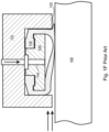
Fig. 1A one approach is to provide a solid,rigid sealing annulus 100 that surrounds theshaft 102 and can be pressed axially into contact with aradial structure 104 that is sealed to theshaft 102 via a supportingstructure 106. In the example ofFig. 1A , thesealing annulus 100 is pneumatically driven against theradial structure 104 when theshaft 102 is not rotating, and is withdrawn from theshaft 102 by aspring 108 when the shaft is rotating. In similar examples, the sealingannulus 100 is driven by a bi-directional pneumatic piston or by mechanical mechanism such as a solenoid. Typically, the standstill shaft seal is activated and deactivated by a controller (not shown), which may be but is not necessarily the same controller that also controls the rotational starting and stopping of the shaft. - While this approach is durable, and is able to seal high pressure process fluids such as high-pressure gasses, nevertheless this approach is intrinsically complex and expensive to manufacture.
- With reference to
Figs. 1B and1C , another approach is to surround theshaft 102 with a hollow,elastomeric tube 110 that is constrained by ahousing 112 and is in fluid communication via aninflation inlet 116 with an inflation source (not shown), for example a source of pressurized nitrogen gas. The cross-section of thetube 110 is shaped such that it normally does not extend beyond thehousing 112 to theshaft 102. However, when theinterior 114 of thetube 110 is pressurized by the inflation source, it expands radially inward beyond thehousing 112 and forms a seal both with thehousing 112 and with theshaft 102.Fig. 1B illustrates the standstill shaft seal when it is open, andFig. 1C illustrates the seal when it is closed. - The approach of
Figs. 1B and1C is simple, and relatively easy to manufacture. However, it can be difficult to provide complex cross-sectional shaping to thetube 110, because it is typically extruded rather than cast. - With reference to
Figs 1D and1E , in a similar approach a shapedelastomeric band 118 is snapped onto a supportingform 120 and installed within thehousing 112. The supportingform 120 is penetrated by theinflation inlet 116, which is directed to a rear surface of theband 118. With reference toFig. 1D , when no pressure is applied via theinflation inlet 116, theelastomeric band 118 remains flat against the supportingform 120, and does not extend beyond thehousing 112. However, with reference toFig. 1E , when pressure is applied via theinflation inlet 116, a pocket of fluid is formed between theband 118 and the supportingform 120, such that theband 118 is extended radially inward out of thehousing 112 and is pressed against theshaft 102, forming a seal. - While these approaches can be effective under some circumstances, they are apt to fail when attempting to form a seal against a high-pressure fluid, such as a gas that is pressurized to 70 Bar or 90 Bar. With reference to
Fig. 1F , if the seal is closed, and a very high pressure is applied by the process fluid upstream of the seal, with no corresponding pressure downstream of the seal, theelastomeric seal 118 can be distorted and even extruded 122 into the gap between theshaft 102 and thehousing 112, such that theband 118 may not fully withdraw from theshaft 102 when the pressure applied via theinflation inlet 116 is withdrawn. In such cases, it may be necessary to resort to a rigid, mechanical approach such as is illustrated inFig. 1A . - Document
US 3 985 365 A discloses a remotely actuated emergency shaft seal. DocumentUS 3 578 342 A discloses a shaft seal. DocumentUS 4 342 336 A discloses a double-acting inflatable seal. DocumentJP H06 344984 A - What is needed, therefore, is a standstill shaft seal that is simple in design, relatively low cost to produce, and able to form a seal that reliably withstands high pressure process fluids.
- The present invention is a fluid pressure driven standstill shaft seal according to appended claims that is simple in design, relatively low cost to produce, and able to form a seal that reliably withstands high pressure process fluids, such as process gasses pressurized to 70 Bar or higher.
- The disclosed seal comprises a flexible band that is installed within an annular housing and surrounds a rotatable shaft. The flexible band comprises a thick, substantially rectangular central region flanked by thinner side regions on either side thereof. The thinner side regions of the flexible band provide radial or axial flexibility to the central region, such that the thick central region is able to be extended through an annular opening in the housing and then retracted therefrom. The thickness of the central region enables it to resist being distorted or extruded when it is pressed against the shaft and subject to a high fluid pressure differential. Pressurized control fluid is applied behind the central region via a control fluid inlet to close the standstill seal.
- The pressurized control fluid that is applied behind the flexible band is controlled by a controller, which in embodiments also controls the rotation of the shaft. While the shaft is rotating, no pressure is applied behind the central region of the flexible band, such that it remains partially or fully within the annular housing and does not contact the shaft. When the shaft is not rotating (i.e. is in a standstill condition), fluid pressure is applied by the controller behind the central region of the flexible band via the control fluid inlet. As a result, the central region of the flexible band is pushed through the annular opening in the housing, and is pressed against the shaft, or against an intermediate structure that is sealed to the shaft, forming a standstill seal therewith. In radial embodiments the change in diameter of the central region is only a small percentage of the full diameter of the flexible band, such that the central region is easily able to accommodate the circumferential compression that is required as the central region is pressed radially inward toward the shaft.
- In some embodiments, the source of the control fluid is independent of the process, and can be, for example, a source of pressurized nitrogen gas, pressurized air, or a pressurized liquid. In other embodiments, the control fluid is the process fluid. In some of these embodiments, a pressure boosting device is used to increase the pressure of the process fluid that is applied behind the flexible band.
- In various embodiments, the flexible band is made from a material such as an elastomer that has sufficient elasticity to reliably spring back to its original shape when it is no longer distorted by applied fluid pressure, such that when the applied fluid pressure is removed, the central region is fully withdrawn from the shaft due to the elasticity of the elastomer. In other embodiments, the flexible band is made from a material that is flexible and durable, but has less elasticity, such as PTFE, such that the flexible band may not have sufficient elasticity to reliably withdraw the central region from the shaft when the control fluid pressure is withdrawn. Some of these embodiments include a pair of annular, toothed springs, each of which has a solid annular region that is clamped in place within the housing, and a toothed annular region that is beneath at least a portion of the side regions of the flexible band. The toothed springs provide added return force that ensures full withdrawal of the central region from the shaft.
- Embodiments further include a pair of rigid annular rings on either side of the thick central region which completely eliminate the possibility that any of the thick region might be extruded into the gap between the housing and the shaft when the standstill seal is engaged. The annular rings can be attached to the central region of the flexible band or they can be fixed to the housing and extend into the gap between the shaft and the housing.
- The standstill seal of the present invention can be implemented together with at least one rotating shaft seal, such as a rotating face mechanical seal. The standstill seal can be implemented upstream or downstream of the rotating shaft seal. Or, if a plurality of rotating shaft seals are included, then the standstill seal can be implemented between the rotating shaft seals. In some embodiments, a plurality of the disclosed standstill seals are deployed, for example one upstream of the rotating shaft seal and one downstream of the rotating shaft seal.
- While the disclosed standstill seal is sometimes described herein as acting radially inward, it will be clear to those of skill in the art that in other embodiments the stationary seal is axial. For example, in embodiments the central region of the flexible band is pressed axially against a radially extending face that is fixed and sealed by an intermediate support structure to the rotating shaft.
- The present invention is a standstill seal configured to form a seal with a rotatable shaft so as to prevent leakage of a process fluid past the standstill seal when the shaft is not rotating. The standstill seal includes a flexible band surrounding the shaft, the flexible band comprising a relatively thicker central region from which relatively thinner side regions extend longitudinally in the direction of sealing of the central region with the shaft, or with an intermediate structure that is sealed to the shaft, when seen in an axial cross-sectional view, the central region being substantially rectangular in cross section, a housing configured to house the flexible band, a pair of cover plates underlying the side regions of the flexible band and configured to prevent the side regions from being deflected past the cover plates, a gap being provided between the cover plates through which the central region of the flexible band can be extended, a control fluid inlet configured to provide fluid communication between a source of pressurized control fluid and a rear surface of the flexible band, and a controller.
- The standstill seal is configured, when the controller applies the pressurized control fluid to the control fluid inlet, to extend the central region of the flexible band through the gap such that it makes contact and forms a seal with the shaft, or with an intermediate structure that is sealed to the shaft. The standstill seal is also configured, when the controller ceases to apply the pressurized control fluid to the flexible band, to withdraw the central region of the flexible band away from the shaft or intermediate structure.
- In embodiments, the standstill seal is configured to apply the central region of the flexible band radially inward against the shaft or against the intermediate structure.
- In any of the above embodiments, the standstill seal can be configured to apply the central region of the flexible band axially against the intermediate structure.
- Any of the above embodiments can further include a pair of rigid annular support rings configured to support sides of the central region of the flexible band when the central region is extended through the gap between the cover plates.
- In any of the above embodiments, the standstill seal can be configured to apply the central region of the flexible band radially inward against the shaft or the intermediate structure, and the annular support rings can include ring gaps that enable the annular support rings to compress radially when the central region is extended radially inward against the shaft or the intermediate structure. In some of these embodiments, the annular support rings are fixed to the central region of the flexible band. And in any of these embodiments, the annular support rings can extend from the housing.
- In any of the above embodiments, the flexible band can include sufficient elasticity to cause the central region to be withdrawn from the shaft or intermediate structure when the controller ceases to apply the pressurized control fluid to the flexible band.
- Any of the above embodiments can further include a spring that is configured to assist the withdrawal of the central region of the flexible band from the shaft or intermediate structure when the controller ceases to apply the pressurized control fluid to the flexible band.
- In some of these embodiments, the standstill seal is configured to apply the central region of the flexible band radially inward against the shaft or the intermediate structure.
- In some of these embodiments, the spring comprises a pair of spaced apart annular bands having solid annular portions from which teeth extend axially toward each other beneath the side regions of the flexible band, an axial gap being provided between the teeth through which the central region of the flexible band can be extended to contact the shaft or the intermediate structure, the teeth being bent radially inward as the central region of the flexible band is pushed toward the shaft. In some of these embodiments, the standstill seal further comprises a pair of rigid annular support rings that extend radially inward from the springs, the rigid annular support rings being configured to support sides of the central region of the flexible band when the central region is applied radially inward against the shaft or the intermediate structure.
- In other of these embodiments, the standstill seal comprises a pair of rigid annular support rings that support opposing sides of the central region of the flexible band when the central region is extended through the gap between the cover plates, the support rings including circumferential gaps enabling radially inward compression of the support rings, and the springs are compression springs applied to the gaps in the support rings.
- In other embodiments that include a spring that is configured to assist the withdrawal of the central region of the flexible band from the shaft or intermediate structure when the controller ceases to apply the pressurized control fluid to the flexible band, the standstill seal is configured to apply the central region of the flexible band axially against the intermediate structure, and the spring comprises a pair of radially concentric annular disks having solid annular portions from which teeth extend radially inward and outward toward each other beneath the side regions of the flexible band, a radial gap being provided between the radially inward and radially outward teeth through which the central region of the flexible band can be extended to contact the intermediate structure, the teeth being bent axially as the central region of the flexible ban dis pushed toward the shaft.
- In any of the above embodiments, the side regions of the flexible band can include portions that are curved in longitudinal cross section, thereby enabling extension of the side regions when the central region is extended through the gap.
- In any of the above embodiments, the standstill seal can be unitary with a rotating shaft seal that is configured to form a seal with the shaft when the shaft is rotating. In some of these embodiments, the standstill seal is configured to form a seal with the shaft or intermediate structure upstream of the rotating shaft seal, while in other of these embodiments the standstill seal is configured to form a seal with the shaft or intermediate structure downstream of the rotating shaft seal.
- In any of the above embodiments, the control fluid can be a gas, or the control fluid can be the process fluid.
- And in any of the above embodiments, the controller can be configured to start and stop the rotation of the shaft, as well as controlling the application of the pressurized control fluid to the flexible band.
- The features and advantages described herein are not all-inclusive and, in particular, many additional features and advantages will be apparent to one of ordinary skill in the art in view of the drawings, specification, and claims. Moreover, it should be noted that the language used in the specification has been principally selected for readability and instructional purposes, and not to limit the scope of the inventive subject matter.
-
-
Fig. 1A is a cross-sectional view of a standstill seal of the prior art that presses a rigid sealing element against an intermediate structure; -
Fig. 1B is a cross-sectional view of a standstill seal of the prior art that forms a seal by inflating a hollow tube to press against a shaft or intermediate structure, the seal being shown in its open configuration; -
Fig. 1C is a cross-sectional view of the prior art seal ofFig. 1B , shown in its closed configuration; -
Fig. 1D is a cross-sectional view of a standstill seal of the prior art that includes a thin, shaped elastomeric band that is snapped onto a supporting form, the seal being shown in its open configuration; -
Fig. 1E is a cross-sectional view of the prior art seal ofFig. 1D , shown in its closed configuration; -
Fig. 1F is a cross-sectional view of the prior art seal ofFig. 1E , wherein the elastomeric band has been extruded into a gap between the shaft and the seal housing due to a pressure differential; -
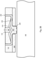
Fig. 2A is an axial cross-sectional view of an embodiment of the present invention in which the seal is opened by radially withdrawing the central region of the flexible band from the shaft due entirely to elasticity of the flexible band, the seal being shown in its open configuration; -
Fig. 2B is an axial cross-sectional view of the embodiment ofFig. 2A shown in its closed configuration; -
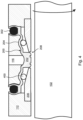
Fig. 3A is an axial cross-sectional view of an embodiment of the present invention in which the radial withdrawal of the central region from the shaft is assisted by springs that include flexible fingers, the seal being shown in its open configuration; -
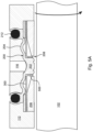
Fig. 3B is an axial cross-sectional view of the embodiment ofFig. 3A shown in its closed configuration; -
Fig. 3C is a perspective view of one of the springs ofFig. 3A ; -
Fig. 4 is an axial cross-sectional view of an embodiment of the present invention in which radial withdrawal of the central region from the shaft is assisted by an elastomeric, compressible tube, the seal being shown in its open configuration; -
Fig. 5A is an axial cross-sectional view of an embodiment similar toFig. 3A , but further including a pair of rigid support rings attached to the central region of the flexible band and configured to support sides of the central region of the flexible band; -
Fig. 5B is a radial cross-sectional view of one of the support rings ofFig. 5A , shown in its open configuration; -
Fig. 5C is a radial cross-sectional view of the support ring ofFig. 5B , shown in its closed configuration; -
Fig. 5D is a radial cross-sectional view similar toFig. 5B , but also including the central region of the flexible band; -
Fig. 5E is an axial cross-sectional view of an embodiment similar toFig. 5A , but in which the support rings are integral with the springs; -
Fig. 5F is an axial cross-sectional view of an embodiment similar toFig. 2A in which compression springs are used to assist in opening the standstill seal by applying a circumferentially expanding force to the gaps support rings; -
Fig. 5G is a radial cross-sectional view of one of the support rings in the embodiment ofFig. 5F , showing the compression spring that applies the circumferentially expanding force to the gap in the support ring, thereby assisting in opening the standstill seal; -
Fig. 5H is an axial cross-sectional view of an embodiment similar toFig. 5A , but wherein the rigid support rings are fixed to the cover plates -
Fig. 6 is an axial cross-sectional view of a unitary dual seal that incorporates the embodiment ofFig. 2A upstream of an end face mechanical rotating shaft seal; -
Fig. 7A is an axial cross- sectional view of an embodiment of the present invention in which the seal is closed by pressing the central region of the flexible band axially against an intermediate structure; and -
Fig. 7B is a radial cross-sectional view of springs that are included in the embodiment ofFig. 7A . - The present invention is a fluid pressure driven standstill shaft seal that is simple in design, relatively low cost to produce, and able to form a seal that reliably withstands high pressure process fluids, such as process gasses pressurized to 70 Bar or higher.
- With reference to the cross-sectional illustration of
Fig. 2A , the disclosed standstill seal comprises aflexible band 200 that is installed within anannular housing 112 and covered by a pair ofannular cover plates 206. Theflexible band 200, thehousing 112, and thecover plates 206 all surround arotatable shaft 102. Theflexible band 200 comprises a thick, substantially rectangularcentral region 202 flanked bythinner side regions 204 on either side thereof. In the embodiment ofFig. 2A , thethinner side regions 204 of theflexible band 200 provide radial flexibility to thecentral region 202, such that the thickcentral region 202 is able to be extended radially inward through anaxial gap 208 between thecover plates 206 and then retracted therefrom. The thickness of thecentral region 202 enables it to withstand high axial pressure differentials when it is pressed against theshaft 102, so that it is not distorted or extruded when the standstill seal is closed. - A pressurized control fluid, such as pressurized nitrogen gas, a pressurized liquid, or pressurized process fluid, is applied behind the
central region 202 via acontrol fluid inlet 116 to close the standstill seal. The pressurized control fluid can be controlled by a controller (not shown), which in embodiments also controls the rotation of theshaft 102. While theshaft 102 is rotating, as is illustrated inFig. 2A , no pressure is applied behind the central region of theflexible band 200, such that it remains partially or fully within theannular housing 112 and coverplates 206, and does not contact theshaft 102. - With reference to
Fig. 2B , when theshaft 102 is not rotating (i.e. is in a standstill condition), pressurized control fluid is applied by the controller behind thecentral region 202 of theflexible band 200 via thecontrol fluid inlet 116. As a result, in the illustrated embodiment, agap 210 filled with the pressurized control fluid is formed behind thecentral region 202 of theflexible band 200, causing thecentral region 202 of theflexible band 200 to be pushed radially inward through theaxial gap 208 between the annular cover plates and pressed against theshaft 102, forming a standstill seal therewith. In other embodiments, the thickcentral region 202 is pressed axially against an intermediate structure that is sealed to theshaft 102, as is discussed in more detail below with reference toFig. 7A . - In the radial embodiment of
Figs. 2A and2B , the change in diameter of thecentral region 202, when deployed, is only a small percentage of the full diameter of theflexible band 200, such that thecentral region 202 is easily able to accommodate the circumferential compression that is required as thecentral region 202 is pressed radially inward toward theshaft 102. - In the embodiment of
Figs. 2A and2B , theflexible band 200 is made from an elastomer or other material that has sufficient elasticity to reliably spring back to its original shape when it is no longer distorted by applied fluid pressure. In the embodiment ofFigs. 3A through 3C , theflexible band 200 is made from a material such as PTFE that is flexible and durable, but has less elasticity, and may not be able, by itself, to reliably withdraw thecentral region 202 from theshaft 102 when the control fluid pressure is withdrawn. - Accordingly, the embodiment of
Figs. 3A and3B includes a pair of opposing annulartoothed springs 300 that provide added radial return force to theside regions 204 of theflexible band 200, ensuring full withdrawal of thecentral region 202 from theshaft 102 when the control fluid pressure behind theflexible band 200 is withdrawn. In the illustrated embodiment, thesides 204 of theflexible band 200 are configured so as to be substantially axial when control fluid pressure is not being applied, so that they can rest upon the axially directedteeth 306 of thespring 300. The flexible band is secured within thehousing 112 by two O-rings 302. - The curved shaping of the
side regions 204 of theflexible band 200 in the embodiment ofFig. 3A provides the additional length that is needed when the standstill seal is closed, as is shown inFig. 3B .Fig. 3C is a perspective view from the side of one of thesprings 300 ofFigs. 3A and3B . It can be seen that thespring 300 includes a solidannular portion 304 and a ring ofaxial teeth 306 that can be bent radially inward as thecentral region 202 of theflexible band 200 is pushed toward theshaft 102. -
Fig. 4 illustrates an embodiment that is similar toFig. 3A , except that the "springs" 400 are elastomeric tubes that surround theshaft 102 within thehousing 112 beneath thesides 204 of theflexible band 200. When thecentral region 202 is deployed, thehollow tubes 400 are flattened, and when the control fluid pressure is released, the elasticity of thehollow tubes 400 assist in returning thecentral region 202 to its previous position within thehousing 112. - With reference to
Figs. 5A , embodiments further include a pair of rigid, annular support rings 500 that are pressed against either side of the thickcentral region 202 to further support thecentral region 202 and completely eliminate the possibility that any of the thickcentral region 202 might be extruded 122 between theannular cover plates 206 and theshaft 102 when the standstill seal is engaged. Of course, the space between the twocover plates 206 is made large enough in these embodiments to accommodate the thicknesses of the support rings 500, as well as the thickness of thecentral region 202 of theflexible band 200. - With reference to
Figs. 5B through 5D , in the illustrated embodiment the annular support rings 500 includegaps 506, such that they do not extend a full 360 degrees about theshaft 102. Thegaps 506 enable the support rings 500 to compress radially inward together with thecentral region 202 of theflexible band 200. InFig. 5B , asupport ring 500 is shown in cross section in its uncompressed state, while inFig. 5B thesupport ring 500 is shown in its compressed state.Fig. 5D shows the relationship between thesupport ring 500 ofFig. 5B and thecentral region 202 of theflexible band 200. - With reference to
Fig. 5E , in similar embodiments, the support rings 500 are integral with thesprings 300 that assist in reopening the standstill seal when the control fluid is depressurized. - In the embodiment of
Figs. 5F and5G , acompressible spring 508 is used to assist the opening of the standstill seal when the control fluid is depressurized, rather than toothed springs 300.Fig. 5F is a cross sectional view similar toFig. 2A , whileFig. 5G is a close-up view of the gap region of asupport ring 500 showing the location and action of thespring 508. Instead of applying a "lifting" force to theside regions 204 of theflexible band 200, thecompression spring 508 ofFig. 5G applies a circumferentially expanding force to the support rings 500, thereby assisting in the retraction of thecentral region 202 of theflexible band 200 from theshaft 102. - With reference to
Fig. 5H , in other embodiments the support rings 500 are fixed to thecover plates 206, and extend into thegap 504 between theshaft 102 and thecover plates 206. - With reference to
Fig. 6 , the standstill seal of the present invention can be implemented together with at least one rotating shaft seal. In the embodiment ofFig. 6 , the standstill seal is implemented upstream of an end face mechanical seal that includes arotating seal face 600 that is sealed to the shaft by anintermediate support structure 602, and a static seal face 604 that is sealed to thehousing 610 and is pushed toward therotating seal face 600 by aspring 606. In the illustrated embodiment, thecentral region 202 of theflexible band 200 is configured to form a seal against theintermediate support structure 602 when theshaft 102 is not rotating, rather than forming a seal directly with theshaft 102. It will be noted that the illustrated embodiment integrates the standstill seal with the end face mechanical seal into a single unit. - In some embodiments, the source of the control fluid is independent of the process, and can be, for example, a source of pressurized nitrogen gas or pressurized air, or a source of a pressurized liquid. In the embodiment of
Fig. 6 , the control fluid is the process fluid. In the illustrated embodiment, process fluid is drawn from apressurized side 608 of the seals, and is passed through apressure boosting device 610 that increases the pressure of the process fluid before it is applied to the rear of theflexible band 200. Avalve 612 that controls the flow of the process fluid into thepressure boosting device 610 is actuated by acontroller 614 that, in embodiments, also controls the stopping and starting of the rotation of theshaft 102. - In similar embodiments, the standstill seal is implemented downstream of the rotating shaft seal. Or, if a plurality of rotating shaft seals are included, the standstill seal can be implemented between the rotating shaft seals. In some embodiments, a plurality of the disclosed standstill seals are deployed, for example one upstream of a rotating shaft seal and one downstream of the rotating shaft seal.
- While the disclosed stationary seal is sometimes described herein as acting radially inward, it will be clear to those of skill in the art that in other embodiments the stationary seal is axial rather than radial. For example, with reference to
Fig. 7A , in embodiments thecentral region 202 of theflexible band 200 is pressed axially against a radially extending face 700 that is sealed by anintermediate support structure 602 to therotating shaft 102. In the illustrated embodiment, theside regions 204 of theflexible band 200 extend radially rather than axially, and with reference toFig. 7B thesprings outer spring 300a directed radially inward and the teeth of theinner spring 300b directed radially outward, with agap 800 provided therebetween through which thecentral region 202 of theflexible band 200 can be deployed. - The foregoing description of the embodiments of the invention has been presented for the purposes of illustration and description. Each and every page of this submission, and all contents thereon, however characterized, identified, or numbered, is considered a substantive part of this application for all purposes, irrespective of form or placement within the application. This specification is not intended to be exhaustive or to limit the invention to the precise form disclosed. Many modifications and variations are possible in light of this disclosure.
- Although the present application is shown in a limited number of forms, the scope of the invention is not limited to just these forms, but is amenable to various changes and modifications. The disclosure presented herein does not explicitly disclose all possible combinations of features that fall within the scope of the invention, as defined by the claims. The features disclosed herein for the various embodiments can generally be interchanged and combined into any combinations that are not self-contradictory without departing from the scope of the invention. In particular, the limitations presented in dependent claims below can be combined with their corresponding independent claims in any number and in any order without departing from the scope of this disclosure, unless the dependent claims are logically incompatible with each other.
Claims (15)
- A standstill seal configured to form a seal with a rotatable shaft (102) so as to prevent leakage of a process fluid past the standstill seal when the shaft is not rotating, the standstill seal comprising:a flexible band (200) surrounding the shaft, the flexible band comprising a relatively thicker central region (202) from which relatively thinner side regions (204) extend longitudinally in the direction of sealing of the central region (202) with the shaft (102), or with an intermediate structure that is sealed to the shaft, when seen in an axial cross-sectional view, the central region (202) being substantially rectangular in longitudinal cross section;a housing (112) configured to house the flexible band;a pair of cover plates (206) underlying the side regions of the flexible band and configured to prevent the side regions from being deflected past the cover plates, a gap (208) being provided between the cover plates through which the central region (202) of the flexible band can be extended;a control fluid inlet (116) configured to provide fluid communication between a source of pressurized control fluid and a rear surface of the flexible band; anda controller;the standstill seal being configured, when the controller applies the pressurized control fluid to the control fluid inlet (116), to press the rear surface of the flexible band (200) toward the gap (208), thereby extending the central region (202) of the flexible band through the gap, such that it makes contact and forms a seal with the shaft (102), or with the intermediate structure that is sealed to the shaft, whereby flexibility of the flexible band (200) is provided by the side regions (204);the standstill seal being configured, when the controller ceases to apply the pressurized control fluid to the control fluid inlet (116), to withdraw the central region (202) of the flexible band away from the shaft (102) or intermediate structure.
- The standstill seal of claim 1, wherein the flexible band (200) includes sufficient elasticity to cause the central region (202) to be withdrawn from the shaft (102) or intermediate structure when the controller ceases to apply the pressurized control fluid to the flexible band.
- The standstill seal of any preceding claim, wherein the side regions of the flexible band (200) include portions that are curved in longitudinal cross section, thereby enabling extension of the side regions (204) when the central region (202) is extended through the gap (208).
- The standstill seal of any preceding claim, wherein the controller is configured to start and stop the rotation of the shaft (102), as well as controlling the application of the pressurized control fluid to the flexible band (200).
- The standstill seal of any previous claim, further comprising a pair of rigid annular support rings (500) configured to support sides of the central region (202) of the flexible band (200) when the central region is extended through the gap (208) between the cover plates (206).
- The standstill seal of 5, wherein the annular support rings (500) are fixed to the central region (202) of the flexible band (200).
- The standstill seal of claim 5, wherein the annular support rings (500) extend from the housing (112).
- The standstill seal of any preceding claim, further comprising a spring (300) that is configured to assist the withdrawal of the central region (202) of the flexible band (200) from the shaft (102) or intermediate structure when the controller ceases to apply the pressurized control fluid to the flexible band.
- The standstill seal of any preceding claim, wherein the standstill seal is configured to apply the central region (202) of the flexible band (200) radially inward against the shaft (102) or against the intermediate structure.
- The standstill seal of any preceding claim, wherein the standstill seal is configured to apply the central region (202) of the flexible band (200) axially against the intermediate structure.
- The standstill seal of claim 5 or claim 6, wherein:the standstill seal is configured to apply the central region (202) of the flexible band (200) radially inward against the shaft (102) or the intermediate structure; andthe annular support rings (500) include ring gaps (506) that enable the annular support rings to compress radially when the central region (202) is extended radially inward against the shaft (102) or the intermediate structure.
- The standstill seal of claim 11, wherein the standstill seal further comprises compression springs (508) applied to the gaps (506) in the support rings (500), the compression springs being configured to assist the withdrawal of the central region (202) of the flexible band (200) from the shaft (102) or intermediate structure when the controller ceases to apply the pressurized control fluid to the flexible band.
- The standstill seal of claim 8, wherein:the standstill seal is configured to apply the central region (202) of the flexible band (200) radially inward against the shaft (102) or the intermediate structure; andthe spring (300) comprises a pair of spaced apart annular bands having solid annular portions (304) from which teeth (306) extend axially toward each other beneath the side regions of the flexible band (200), an axial gap (800) being provided between the teeth through which the central region of the flexible band can be extended to contact the shaft (102) or the intermediate structure, the teeth being bent radially inward as the central region (202) of the flexible band is pushed toward the shaft.
- The standstill seal of any of claims 1- 4, wherein:the standstill seal is configured to apply the central region (202) of the flexible band (200) radially inward against the shaft (102) or the intermediate structure;the standstill seal comprises a spring (300) that is configured to assist the withdrawal of the central region (202) of the flexible band (200) from the shaft (102) or intermediate structure when the controller ceases to apply the pressurized control fluid to the flexible band; andthe standstill seal further comprises a pair of rigid annular support rings (500) configured to support sides of the central region (202) of the flexible band (200) when the central region is extended through the gap (208) between the cover plates (206), said rigid annular support rings extending radially inward from the springs.
- The standstill seal of any of claims 1- 4, wherein:the standstill seal is configured to apply the central region (202) of the flexible band (200) axially against the intermediate structure; andthe standstill seal further comprises a spring (300) that is configured to assist the withdrawal of the central region (202) of the flexible band (200) from the shaft (102) or intermediate structure when the controller ceases to apply the pressurized control fluid to the flexible band;the spring (300) comprising a pair of radially concentric annular disks having solid annular portions (304) from which teeth (306) extend radially inward and outward toward each other beneath the side regions (204) of the flexible band (200), a radial gap being provided between the radially inward and radially outward teeth through which the central region (200) of the flexible band can be extended to contact the intermediate structure, the teeth (306) being bent axially as the central region (202) of the flexible band (200) is pushed toward the shaft (102).
Applications Claiming Priority (2)
| Application Number | Priority Date | Filing Date | Title |
|---|---|---|---|
| US17/742,851 US12129928B2 (en) | 2022-05-12 | 2022-05-12 | Pneumatic standstill shaft seal |
| PCT/IB2023/054584 WO2023218290A1 (en) | 2022-05-12 | 2023-05-03 | Pneumatic standstill shaft seal |
Publications (4)
| Publication Number | Publication Date |
|---|---|
| EP4295063A1 EP4295063A1 (en) | 2023-12-27 |
| EP4295063A4 EP4295063A4 (en) | 2024-05-29 |
| EP4295063C0 EP4295063C0 (en) | 2025-07-02 |
| EP4295063B1 true EP4295063B1 (en) | 2025-07-02 |
Family
ID=88236872
Family Applications (1)
| Application Number | Title | Priority Date | Filing Date |
|---|---|---|---|
| EP23734440.3A Active EP4295063B1 (en) | 2022-05-12 | 2023-05-03 | Pneumatic standstill shaft seal |
Country Status (7)
| Country | Link |
|---|---|
| US (1) | US12129928B2 (en) |
| EP (1) | EP4295063B1 (en) |
| JP (1) | JP7637799B2 (en) |
| KR (1) | KR102898455B1 (en) |
| CN (1) | CN117396691A (en) |
| AU (1) | AU2023203937B2 (en) |
| WO (1) | WO2023218290A1 (en) |
Family Cites Families (24)
| Publication number | Priority date | Publication date | Assignee | Title |
|---|---|---|---|---|
| US3124502A (en) * | 1964-03-10 | Composite fibrous lubricant packing | ||
| US2548412A (en) * | 1948-05-24 | 1951-04-10 | Hinderliter Tool Company Divis | Sealing unit for well casing heads |
| DE933842C (en) * | 1953-06-13 | 1955-10-06 | Voith Gmbh J M | Gap seal |
| US3178779A (en) * | 1962-06-28 | 1965-04-20 | North American Aviation Inc | Multi-cell inflatable seal |
| US3578342A (en) | 1969-01-14 | 1971-05-11 | Satterthwaite James G | Shaft seal |
| US3689082A (en) * | 1970-02-03 | 1972-09-05 | Satterthwaite James G | Inflatable seal |
| FR2243619A5 (en) * | 1973-09-06 | 1975-04-04 | Joint Francais | |
| US3985365A (en) | 1975-11-06 | 1976-10-12 | Bartholomew Thomas Catanzaro | Remotely actuated emergency shaft seal |
| SE413200B (en) | 1978-08-14 | 1980-04-28 | Asea Atom Ab | SEALING PRESSURE SEALING DEVICE |
| US4342336A (en) * | 1979-10-03 | 1982-08-03 | Satterthwaite J Glenn | Double-acting inflatable seal |
| US4381114A (en) * | 1981-11-23 | 1983-04-26 | Cameron Iron Works, Inc. | Packoff and seal ring assembly with injected plastic packing |
| JPH06100191B2 (en) * | 1989-04-14 | 1994-12-12 | 株式会社日立製作所 | Pump sealing device |
| FR2665499B1 (en) * | 1990-07-10 | 1994-01-28 | Joint Francais | SEALING DEVICE WITH INFLATABLE JOINT FOR MOBILE DOOR OR PANEL. |
| JPH06344984A (en) | 1993-06-07 | 1994-12-20 | Nippon Marine Techno Kk | Bulkhead sealing device for ship |
| JPH07239039A (en) | 1994-02-28 | 1995-09-12 | Ntn Corp | Device for sealing rotating shaft |
| US5524905A (en) * | 1994-09-28 | 1996-06-11 | Greene, Tweed Of Delaware, Inc. | Sealing assembly with T-shaped seal ring and anti-extrusion rings |
| US5890535A (en) * | 1997-07-23 | 1999-04-06 | Abb Vetco Gray Inc. | Diverter flow line seal |
| US6942224B2 (en) * | 2003-07-16 | 2005-09-13 | Steris Inc. | Inflatable seal |
| US10077621B2 (en) * | 2013-06-13 | 2018-09-18 | Vetco Gray, LLC | Diverter flow line insert packer seal |
| CN105298553B (en) | 2014-06-17 | 2018-03-06 | 斗山重工业株式会社 | brush seal assembly |
| US10316604B2 (en) * | 2014-07-02 | 2019-06-11 | Utex Industries, Inc. | Inflatable seal with fabric expansion restriction |
| MX380065B (en) | 2014-12-08 | 2025-03-11 | Flowserve Pte Ltd | Bearing Seal with Static Sealing Tapered O-Ring Interface |
| CN206988432U (en) | 2017-07-27 | 2018-02-09 | 浙江长江搅拌设备有限公司 | A kind of flow blockage device of mechanical seal |
| US11506217B2 (en) | 2020-01-21 | 2022-11-22 | John Crane Uk Limited | Porous carbon containment or separation seal |
-
2022
- 2022-05-12 US US17/742,851 patent/US12129928B2/en active Active
-
2023
- 2023-05-03 AU AU2023203937A patent/AU2023203937B2/en active Active
- 2023-05-03 KR KR1020237029915A patent/KR102898455B1/en active Active
- 2023-05-03 EP EP23734440.3A patent/EP4295063B1/en active Active
- 2023-05-03 CN CN202380009849.2A patent/CN117396691A/en active Pending
- 2023-05-03 JP JP2023571795A patent/JP7637799B2/en active Active
- 2023-05-03 WO PCT/IB2023/054584 patent/WO2023218290A1/en not_active Ceased
Also Published As
| Publication number | Publication date |
|---|---|
| WO2023218290A1 (en) | 2023-11-16 |
| EP4295063A4 (en) | 2024-05-29 |
| AU2023203937A1 (en) | 2023-11-30 |
| KR102898455B1 (en) | 2025-12-09 |
| US12129928B2 (en) | 2024-10-29 |
| US20230366469A1 (en) | 2023-11-16 |
| EP4295063C0 (en) | 2025-07-02 |
| EP4295063A1 (en) | 2023-12-27 |
| CN117396691A (en) | 2024-01-12 |
| KR20230159391A (en) | 2023-11-21 |
| AU2023203937B2 (en) | 2024-08-29 |
| JP2024523122A (en) | 2024-06-28 |
| JP7637799B2 (en) | 2025-02-28 |
Similar Documents
| Publication | Publication Date | Title |
|---|---|---|
| KR100472395B1 (en) | Seal | |
| US9376884B2 (en) | Packing element | |
| US5454572A (en) | Mechanical end face seal system | |
| US2214261A (en) | Sealing device | |
| JPS6323430B2 (en) | ||
| EP0636821B1 (en) | Shaft seal for butterfly valve | |
| KR920001237B1 (en) | Double Block-Vent Valve Unit | |
| US6979002B2 (en) | Sealing apparatus having sequentially engageable seals | |
| JPH0650437A (en) | Pressure release type seal structure | |
| JP2013150986A5 (en) | Filtration system and spiral element | |
| NO171807B (en) | Butterfly Valves | |
| US20100258311A1 (en) | Casing Patch and Seal | |
| US7735562B2 (en) | Tieback seal system and method | |
| EP2321561B1 (en) | Improvements in and relating to spring energised plastic seals | |
| US20150115535A1 (en) | Seal having variable elastic modulus | |
| KR960703217A (en) | GATE VALVE | |
| US12129928B2 (en) | Pneumatic standstill shaft seal | |
| JPH0686918B2 (en) | Flexible joint means | |
| CN116438396A (en) | Flexible Sealing Membranes and Sealing Assemblies for Rotary Shaft Equipment | |
| CN114811073B (en) | A sealing element, a sealing assembly comprising the same, and a sealing valve | |
| US11448229B2 (en) | Seal assembly | |
| EP3601854B1 (en) | Shock wave mechanical seal | |
| CN114508603B (en) | Sealing valve | |
| JP2574119Y2 (en) | Sealing device | |
| JPH0665558B2 (en) | Bulkhead seal |
Legal Events
| Date | Code | Title | Description |
|---|---|---|---|
| STAA | Information on the status of an ep patent application or granted ep patent |
Free format text: STATUS: UNKNOWN |
|
| STAA | Information on the status of an ep patent application or granted ep patent |
Free format text: STATUS: THE INTERNATIONAL PUBLICATION HAS BEEN MADE |
|
| PUAI | Public reference made under article 153(3) epc to a published international application that has entered the european phase |
Free format text: ORIGINAL CODE: 0009012 |
|
| STAA | Information on the status of an ep patent application or granted ep patent |
Free format text: STATUS: REQUEST FOR EXAMINATION WAS MADE |
|
| 17P | Request for examination filed |
Effective date: 20230706 |
|
| AK | Designated contracting states |
Kind code of ref document: A1 Designated state(s): AL AT BE BG CH CY CZ DE DK EE ES FI FR GB GR HR HU IE IS IT LI LT LU LV MC ME MK MT NL NO PL PT RO RS SE SI SK SM TR |
|
| A4 | Supplementary search report drawn up and despatched |
Effective date: 20240430 |
|
| RIC1 | Information provided on ipc code assigned before grant |
Ipc: F16J 15/10 20060101ALI20240424BHEP Ipc: F16J 15/02 20060101ALI20240424BHEP Ipc: F16J 15/38 20060101ALI20240424BHEP Ipc: F16J 15/34 20060101ALI20240424BHEP Ipc: F16J 15/00 20060101ALI20240424BHEP Ipc: F16J 15/18 20060101ALI20240424BHEP Ipc: F16J 15/32 20160101ALI20240424BHEP Ipc: F16J 15/46 20060101AFI20240424BHEP |
|
| STAA | Information on the status of an ep patent application or granted ep patent |
Free format text: STATUS: EXAMINATION IS IN PROGRESS |
|
| 17Q | First examination report despatched |
Effective date: 20241008 |
|
| REG | Reference to a national code |
Ref country code: DE Ref legal event code: R079 Free format text: PREVIOUS MAIN CLASS: F16J0015460000 Ipc: F16J0015321200 Ref country code: DE Ref legal event code: R079 Ref document number: 602023004556 Country of ref document: DE Free format text: PREVIOUS MAIN CLASS: F16J0015460000 Ipc: F16J0015321200 |
|
| GRAP | Despatch of communication of intention to grant a patent |
Free format text: ORIGINAL CODE: EPIDOSNIGR1 |
|
| STAA | Information on the status of an ep patent application or granted ep patent |
Free format text: STATUS: GRANT OF PATENT IS INTENDED |
|
| RIC1 | Information provided on ipc code assigned before grant |
Ipc: F16J 15/10 20060101ALI20250304BHEP Ipc: F16J 15/02 20060101ALI20250304BHEP Ipc: F16J 15/46 20060101ALI20250304BHEP Ipc: F16J 15/38 20060101ALI20250304BHEP Ipc: F16J 15/34 20060101ALI20250304BHEP Ipc: F16J 15/00 20060101ALI20250304BHEP Ipc: F16J 15/322 20160101ALI20250304BHEP Ipc: F16J 15/3212 20160101AFI20250304BHEP |
|
| INTG | Intention to grant announced |
Effective date: 20250313 |
|
| GRAS | Grant fee paid |
Free format text: ORIGINAL CODE: EPIDOSNIGR3 |
|
| GRAA | (expected) grant |
Free format text: ORIGINAL CODE: 0009210 |
|
| STAA | Information on the status of an ep patent application or granted ep patent |
Free format text: STATUS: THE PATENT HAS BEEN GRANTED |
|
| DAV | Request for validation of the european patent (deleted) | ||
| DAX | Request for extension of the european patent (deleted) | ||
| AK | Designated contracting states |
Kind code of ref document: B1 Designated state(s): AL AT BE BG CH CY CZ DE DK EE ES FI FR GB GR HR HU IE IS IT LI LT LU LV MC ME MK MT NL NO PL PT RO RS SE SI SK SM TR |
|
| REG | Reference to a national code |
Ref country code: GB Ref legal event code: FG4D |
|
| REG | Reference to a national code |
Ref country code: CH Ref legal event code: EP |
|
| REG | Reference to a national code |
Ref country code: IE Ref legal event code: FG4D |
|
| U01 | Request for unitary effect filed |
Effective date: 20250708 |
|
| U07 | Unitary effect registered |
Designated state(s): AT BE BG DE DK EE FI FR IT LT LU LV MT NL PT RO SE SI Effective date: 20250711 |
|
| PG25 | Lapsed in a contracting state [announced via postgrant information from national office to epo] |
Ref country code: IS Free format text: LAPSE BECAUSE OF FAILURE TO SUBMIT A TRANSLATION OF THE DESCRIPTION OR TO PAY THE FEE WITHIN THE PRESCRIBED TIME-LIMIT Effective date: 20251102 |
|
| PG25 | Lapsed in a contracting state [announced via postgrant information from national office to epo] |
Ref country code: NO Free format text: LAPSE BECAUSE OF FAILURE TO SUBMIT A TRANSLATION OF THE DESCRIPTION OR TO PAY THE FEE WITHIN THE PRESCRIBED TIME-LIMIT Effective date: 20251002 |
|
| PG25 | Lapsed in a contracting state [announced via postgrant information from national office to epo] |
Ref country code: HR Free format text: LAPSE BECAUSE OF FAILURE TO SUBMIT A TRANSLATION OF THE DESCRIPTION OR TO PAY THE FEE WITHIN THE PRESCRIBED TIME-LIMIT Effective date: 20250702 |
|
| PG25 | Lapsed in a contracting state [announced via postgrant information from national office to epo] |
Ref country code: GR Free format text: LAPSE BECAUSE OF FAILURE TO SUBMIT A TRANSLATION OF THE DESCRIPTION OR TO PAY THE FEE WITHIN THE PRESCRIBED TIME-LIMIT Effective date: 20251003 |
|
| PG25 | Lapsed in a contracting state [announced via postgrant information from national office to epo] |
Ref country code: CZ Free format text: LAPSE BECAUSE OF FAILURE TO SUBMIT A TRANSLATION OF THE DESCRIPTION OR TO PAY THE FEE WITHIN THE PRESCRIBED TIME-LIMIT Effective date: 20250702 |
|
| PG25 | Lapsed in a contracting state [announced via postgrant information from national office to epo] |
Ref country code: PL Free format text: LAPSE BECAUSE OF FAILURE TO SUBMIT A TRANSLATION OF THE DESCRIPTION OR TO PAY THE FEE WITHIN THE PRESCRIBED TIME-LIMIT Effective date: 20250702 |
|
| PG25 | Lapsed in a contracting state [announced via postgrant information from national office to epo] |
Ref country code: RS Free format text: LAPSE BECAUSE OF FAILURE TO SUBMIT A TRANSLATION OF THE DESCRIPTION OR TO PAY THE FEE WITHIN THE PRESCRIBED TIME-LIMIT Effective date: 20251002 |
|
| PG25 | Lapsed in a contracting state [announced via postgrant information from national office to epo] |
Ref country code: ES Free format text: LAPSE BECAUSE OF FAILURE TO SUBMIT A TRANSLATION OF THE DESCRIPTION OR TO PAY THE FEE WITHIN THE PRESCRIBED TIME-LIMIT Effective date: 20250702 |
|
| PG25 | Lapsed in a contracting state [announced via postgrant information from national office to epo] |
Ref country code: SM Free format text: LAPSE BECAUSE OF FAILURE TO SUBMIT A TRANSLATION OF THE DESCRIPTION OR TO PAY THE FEE WITHIN THE PRESCRIBED TIME-LIMIT Effective date: 20250702 |
|
| PG25 | Lapsed in a contracting state [announced via postgrant information from national office to epo] |
Ref country code: SK Free format text: LAPSE BECAUSE OF FAILURE TO SUBMIT A TRANSLATION OF THE DESCRIPTION OR TO PAY THE FEE WITHIN THE PRESCRIBED TIME-LIMIT Effective date: 20250702 |
|
| PLBE | No opposition filed within time limit |
Free format text: ORIGINAL CODE: 0009261 |
|
| STAA | Information on the status of an ep patent application or granted ep patent |
Free format text: STATUS: NO OPPOSITION FILED WITHIN TIME LIMIT |