EP4295027B1 - Ringförmige booster-rakete - Google Patents
Ringförmige booster-rakete Download PDFInfo
- Publication number
- EP4295027B1 EP4295027B1 EP21810768.8A EP21810768A EP4295027B1 EP 4295027 B1 EP4295027 B1 EP 4295027B1 EP 21810768 A EP21810768 A EP 21810768A EP 4295027 B1 EP4295027 B1 EP 4295027B1
- Authority
- EP
- European Patent Office
- Prior art keywords
- annular
- nozzle
- casing
- rocket
- booster
- Prior art date
- Legal status (The legal status is an assumption and is not a legal conclusion. Google has not performed a legal analysis and makes no representation as to the accuracy of the status listed.)
- Active
Links
Images


Classifications
-
- F—MECHANICAL ENGINEERING; LIGHTING; HEATING; WEAPONS; BLASTING
- F02—COMBUSTION ENGINES; HOT-GAS OR COMBUSTION-PRODUCT ENGINE PLANTS
- F02K—JET-PROPULSION PLANTS
- F02K9/00—Rocket-engine plants, i.e. plants carrying both fuel and oxidant therefor; Control thereof
- F02K9/97—Rocket nozzles
-
- B—PERFORMING OPERATIONS; TRANSPORTING
- B64—AIRCRAFT; AVIATION; COSMONAUTICS
- B64G—COSMONAUTICS; VEHICLES OR EQUIPMENT THEREFOR
- B64G1/00—Cosmonautic vehicles
- B64G1/22—Parts of, or equipment specially adapted for fitting in or to, cosmonautic vehicles
- B64G1/40—Arrangements or adaptations of propulsion systems
- B64G1/403—Solid propellant rocket engines
-
- F—MECHANICAL ENGINEERING; LIGHTING; HEATING; WEAPONS; BLASTING
- F02—COMBUSTION ENGINES; HOT-GAS OR COMBUSTION-PRODUCT ENGINE PLANTS
- F02K—JET-PROPULSION PLANTS
- F02K9/00—Rocket-engine plants, i.e. plants carrying both fuel and oxidant therefor; Control thereof
- F02K9/08—Rocket-engine plants, i.e. plants carrying both fuel and oxidant therefor; Control thereof using solid propellants
- F02K9/32—Constructional parts; Details not otherwise provided for
- F02K9/34—Casings; Combustion chambers; Liners thereof
-
- F—MECHANICAL ENGINEERING; LIGHTING; HEATING; WEAPONS; BLASTING
- F02—COMBUSTION ENGINES; HOT-GAS OR COMBUSTION-PRODUCT ENGINE PLANTS
- F02K—JET-PROPULSION PLANTS
- F02K9/00—Rocket-engine plants, i.e. plants carrying both fuel and oxidant therefor; Control thereof
- F02K9/74—Rocket-engine plants, i.e. plants carrying both fuel and oxidant therefor; Control thereof combined with another jet-propulsion plant
- F02K9/76—Rocket-engine plants, i.e. plants carrying both fuel and oxidant therefor; Control thereof combined with another jet-propulsion plant with another rocket-engine plant; Multistage rocket-engine plants
- F02K9/763—Rocket-engine plants, i.e. plants carrying both fuel and oxidant therefor; Control thereof combined with another jet-propulsion plant with another rocket-engine plant; Multistage rocket-engine plants with solid propellant
-
- F—MECHANICAL ENGINEERING; LIGHTING; HEATING; WEAPONS; BLASTING
- F02—COMBUSTION ENGINES; HOT-GAS OR COMBUSTION-PRODUCT ENGINE PLANTS
- F02K—JET-PROPULSION PLANTS
- F02K9/00—Rocket-engine plants, i.e. plants carrying both fuel and oxidant therefor; Control thereof
- F02K9/80—Rocket-engine plants, i.e. plants carrying both fuel and oxidant therefor; Control thereof characterised by thrust or thrust vector control
- F02K9/88—Rocket-engine plants, i.e. plants carrying both fuel and oxidant therefor; Control thereof characterised by thrust or thrust vector control using auxiliary rocket nozzles
-
- F—MECHANICAL ENGINEERING; LIGHTING; HEATING; WEAPONS; BLASTING
- F42—AMMUNITION; BLASTING
- F42B—EXPLOSIVE CHARGES, e.g. FOR BLASTING, FIREWORKS, AMMUNITION
- F42B15/00—Self-propelled projectiles or missiles, e.g. rockets; Guided missiles
-
- F—MECHANICAL ENGINEERING; LIGHTING; HEATING; WEAPONS; BLASTING
- F05—INDEXING SCHEMES RELATING TO ENGINES OR PUMPS IN VARIOUS SUBCLASSES OF CLASSES F01-F04
- F05D—INDEXING SCHEME FOR ASPECTS RELATING TO NON-POSITIVE-DISPLACEMENT MACHINES OR ENGINES, GAS-TURBINES OR JET-PROPULSION PLANTS
- F05D2250/00—Geometry
- F05D2250/20—Three-dimensional
- F05D2250/28—Three-dimensional patterned
- F05D2250/281—Three-dimensional patterned threaded
Definitions
- the invention is in the field of booster rockets for flight vehicles, such as missiles.
- Booster rockets are sometimes used to add thrust to flight vehicles, such as missiles. Certain limitations are sometimes present regarding the characteristics for add-on booster rockets.
- US 4,964,339 A discloses multiple stage rocked propelled missile systems.
- US 3,806,064 A discloses missile configurations, controls and utilization techniques.
- a booster rocket has an annular shape, allowing it to be placed around an object, with one or more nozzle insert defining one or more nozzles of the rocket.
- a booster rocket is mechanically coupled to a nozzle of a main propulsion system, such as a jet, without interfering with operation of the jet.
- a booster rocket is couplable to a part of existing flight vehicle, adding thrust without expanding the envelope of the flight vehicle.
- a booster rocket is mechanically coupled to a part of main propulsion system, and remains so coupled even after the propellant (fuel) of the booster rocket is expended.
- a booster rocket includes: an annular casing defining an annular space therewithin, and having a central opening; a solid rocket fuel in the annular space; and one or more nozzle pieces mechanically coupled to the annular casing, defining one or more nozzles at an aft end of the annular casing, wherein the multiple casing parts include an inner casing part and an outer casing part, the inner casing part and the outer casing part are threadedly coupled together.
- the one or more nozzle pieces includes an annular nozzle piece that defines an annular nozzle.
- the annular nozzle piece is bolted to the annular casing.
- the booster rocket further includes a seal between the annular nozzle piece and the annular casing.
- the seal is a silicone seal.
- the annular nozzle piece defines the annular nozzle in combination with an inner nozzle insert that is attached to the annular casing.
- the inner nozzle insert is bonded and attached by shear bolts to the annular casing.
- the annular nozzle piece and the inner nozzle insert together constitute a throat insert set.
- the annular nozzle piece has protrusions protruding inward from an inner edge, the protrusions facilitating maintaining an annular gap of the annular nozzle.
- the annular nozzle piece is made of a metallic material.
- the annular nozzle piece is made of a non-metallic material.
- the annular nozzle piece is made of aluminum.
- the annular nozzle piece and the annular casing are made of the same material.
- the annular nozzle piece is made of a phenolic material.
- the one or more nozzle pieces includes multiple nozzle pieces.
- the multiple nozzle pieces are circumferentially spaced around aft end of the annular casing.
- the multiple nozzle pieces are located in circular openings in the aft end of the annular casing.
- the booster rocket further includes an igniter coupled to an outer surface of the annular casing, with the igniter operatively coupled to the solid rocket fuel, to facilitate initiation of combustion of the solid rocket fuel.
- the booster rocket further includes an ignition booster on an inner wall of the annular casing, with the ignition booster operatively coupled to the igniter and the solid rocket fuel, to facilitate initiation of combustion of the solid rocket fuel.
- the casing is made of metal.
- the casing is made of sheet metal.
- the inner casing part and the outer casing part are threadedly coupled together.
- the casing includes a liner along at least part of an inside surface of the casing, with the liner at least in part defining the annular space.
- the fuel is configured within the annular space for end burning.
- the fuel is configured within the annular space for core burning.
- the fuel is configured within the annular space for both end burning and core burning.
- the fuel has one or more channels therein.
- the one or more channels include at least one channel in a longitudinal direction.
- the fuel is along an outer wall of the casing, with a space between the fuel and an inner wall of the casing.
- the booster rocket further includes an igniter in the casing.
- the booster rocket is in combination with an object to which the rocket booster is mechanically coupled.
- the object is a part of a flight vehicle.
- the object is an aft part of a flight vehicle.
- the object is part of a propulsion device at an aft end of the flight vehicle.
- the object is centered on a longitudinal centerline of the flight vehicle.
- the rocket booster is centered around a longitudinal centerline of the flight vehicle.
- the object is a turbojet engine.
- the object protrudes from an aft end of a fuselage of the flight vehicle.
- the flight vehicle is a missile.
- a missile includes: a fuselage; a main propulsion system that includes a nozzle protruding aftward from the fuselage; and a booster rocket around the nozzle.
- the booster rocket includes: an annular casing defining an annular space therewithin, and having a central opening through which the nozzle protrudes; a solid rocket fuel in the annular space; and one or more nozzle pieces mechanically coupled to the annular casing, defining one or more nozzles at an aft end of the annular casing, wherein the multiple casing parts include an inner casing part and an outer casing part, the inner casing part and the outer casing part are threadedly coupled together.
- a method for increasing thrust of a flight vehicle includes the steps of: placing an annular booster rocket around a part of a main propulsion system of the flight vehicle; and burning fuel of the booster rocket to product thrust.
- a rocket booster has an annular shape, with a casing defining an annular space therewithin, and a solid rocket fuel in the annular spacing.
- the rocket booster also includes one or more nozzle pieces, mechanically coupled to the casing, that define one or more nozzles at the aft side of the rocket booster.
- the rocket booster may be mechanically coupled to an object protruding from the back of a fuselage of a flight vehicle, such as a missile.
- the rocket booster may be placed around an aft turbojet nozzle of the flight vehicle. This allows the rocket booster to be used in situations where primary propulsion must be running both before and after (and perhaps during) the firing of the rocket booster.
- the rocket booster also advantageously may provide thrust along the centerline of the flight vehicle, and may be used in situations where there is a requirement to maintain the booster as part of the flight vehicle throughout flight.
- the rocket booster may have a truncated aerospike nozzle configuration, and may provide for a low-drag additional propulsion system that does not interfere with the operation of the primary propulsion system. Further, the casing of the rocket booster may double as a rear jet engine mount.
- a flight vehicle 10 such as a missile, includes a fuselage 14, with a main propulsion device 16 protruding from or as part of an aft end 20 of the fuselage 14.
- the main propulsion device 16 may be a turbojet engine.
- the protruding part of the main propulsion device 16 may be a nozzle 22 of the turbojet engine.
- a booster rocket 30 may be mounted on and around the nozzle 22, with the nozzle 22 protruding through a central opening 32 in the booster rocket 30.
- the booster rocket 30 may thereby provide additional thrust to the flight vehicle 10, without interfering with the operability of the main propulsion device 16.
- the booster rocket 30 may provide the additional thrust without affecting the general envelope of the flight vehicle 10.
- the missile (flight vehicle) 10 may have additional features, for example fins 34 or other wings or control surfaces.
- additional features include a guidance system, a communications system, various types of sensors or information-gathering features, and a payload such as a warhead or other destructive material.
- the booster rocket 30 is shown mounted around the nozzle 22, but it will be appreciated that the nozzle 22 is but one example of a broader category of objects to which the booster rocket 30 is mounted.
- the object may alternatively be other sorts of structures, whether provide a propulsive function or not, that pass into or through the central opening 32 of the booster rocket 30.
- both the object (the nozzle 22 in the illustrated embodiment) and the booster rocket 30 are centered around a longitudinal centerline (central axis) 36 of the flight vehicle 10.
- the booster rocket 30 has one or more one or more nozzle pieces, defining one or more nozzles for output of the pressurized gases from the booster 30.
- the one or more nozzle pieces includes a ring-shaped annular piece that defines (at least in part) an annular nozzle.
- the one or more nozzle pieces include multiple nozzle pieces that define multiple nozzles, for instance circumferentially spaced about the booster 30.
- the flight vehicle 10 is just one example of the many types of flight vehicles that may receive the booster rocket 30, in order to produce additional thrust.
- Alternatives to the missile are other types of vehicles with main propulsion devices of any of a variety of suitable types.
- Figs. 3 and 4 show further details of one embodiment of the booster rocket 30.
- the rocket 30 includes an annular casing 40 that defines an annular space 42 where a solid rocket fuel (propellant) 44 is located.
- the fuel 44 may optionally have one or more channels therein, of any of various suitable configurations, to control the burn rate.
- Such channels when present, may include at least one channel in a longitudinal (axial) direction, parallel to an axis of the flight vehicle 10 (the centerline 36), which may be coincident with axes of both the booster rocket 30 and the object (such as the turbojet nozzle 22) to and around which the booster rocket 30 is mounted.
- the fuel 44 is located between the inner part 60 and the outer part 62. Combustion of the fuel 44 occurs in the annular space 42, which acts as a combustion chamber for the booster rocket 30.
- the casing 40 is formed out of two separate pieces or parts 60 and 62, which are threadedly joined together.
- the parts 60 and 62 are formed separately and screwed together along threads 65, after an annular solid fuel (propellant) 44 is put into place.
- the threaded connection may be sealed, as with a silicone sealant, to prevent egress of hot gasses.
- Once the parts 60 and 62 are joined together the fuel 44 is in an annular space 42 defined by the parts 60 and 62.
- the fuel 44 can be ignited by an igniter 67 that is secured in a hole in the outer casing part 62.
- An ignition booster 68 may be placed on the inner casing part 60, to work in combination with the igniter 67 to facilitate ignition of the fuel 44.
- the ignition booster 68 may be any of a variety of easily ignitable/combustible materials.
- the casing parts 60 and 62 may have a liner 69 on their surfaces that define the annular space 42 that acts as the combustion chamber.
- the liner 69 may be a heat-resistant material that provides some protection to the casing parts 60 and 62.
- the liner 69 may be made of any of a variety of suitable materials, non-limiting examples being aluminum and cardboard.
- the inner casing part 60 has a cylindrical forward section 70 and an inwardly-angled aft section 72.
- the inner casing part sections 70 and 72 may correspond in exterior shape to an object to which the rocket booster 30, for example to the shape of a turbojet nozzle. Further, the inwardly-angled aft section 72 may constitute a truncated aerospike shape, which may provide for efficiency in the operation of the booster rocket 30.
- the inner casing part 60 includes a forward end 74 which constitutes the forward end of the rocket booster 30.
- the forward end 74 may have mechanical connections 82 and 84 thereupon, which may be configured to connect the booster rocket 30 to a flight vehicle.
- the mechanical connections 82 and 84 may be any of a variety of suitable clips, clamps, or other suitable mechanisms for making a connection.
- the inner casing part 60 also includes an externally threaded outer portion 86 that is used to make the threaded connection with an internally threaded cylindrical aft section 88 of the outer casing part 62.
- the outer casing part 62 includes a cylindrical forward section 96, and an inwardly-sloped aft section 98 that is bent inward toward the turbojet nozzle 22.
- the slope of the aft section 98 may correspond to a slope of the turbojet nozzle 22.
- the igniter 67 may be located in the sloped aft section 98, and the ignition booster 68 may be located on an outer surface of the cylindrical section 70 of the inner casing part 60.
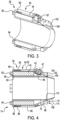
- the booster rocket 30 includes a ring-shaped annular nozzle piece 102.
- the nozzle piece 102 is mechanically coupled or attached to the aft end of the annular casing 40, more specifically to the aft side of the sloped aft section 98 of the outer casing part 62.
- the nozzle piece 102 may be bolted to the aft section 98.
- a seal 104 such as a silicone seal, may be provided between the nozzle piece 102 and the aft section 98.
- the annular nozzle piece 102 may be part of a throat insert set 106 that also includes an inner nozzle insert 108.
- the inner nozzle insert 108 has an annular shape, a band that fits around the inner casing part 60.
- the inner nozzle insert 108 is attached to an other surface of the inner casing part 60.
- the inner nozzle insert 108 may be located in a slot 110 at or close to the intersection of the cylindrical forward section 70 and the inwardly-angled aft section 72.
- the inner nozzle insert 108 may be bonded and attached by shear bolts to the inner casing part 60.
- annular nozzle piece 102 and the inner nozzle insert 108 together define an annular nozzle 114 through which pressurized gases from the combustion of the fuel 44 exit the booster rocket 30 at its aft end.
- the annular nozzle 114 is an annular gap between the outer casing part 52 and an outer surface of the turbojet nozzle 22 that serves as the object around which the rocket booster 30 is installed.
- the annular nozzle piece 102 and the inner nozzle insert 108 may be made of any of a variety of suitable materials.
- the piece 102 and/or the insert 108 may be made of a metallic or nonmetallic material.
- they may be made of the same material as the casing parts 60 and 62, for example being made of aluminum.
- the annular nozzle piece 102 and/or the inner nozzle insert 108 may be made of a phenolic material or other suitable non-metallic material.
- the use of the nozzle piece 102 and the nozzle insert 108 to define the annular nozzle 114 may facilitate better performance of the booster rocket 30.
- the use of the throat insert set 106 may provide for better tolerances in the annular gap of the annular nozzle 114, may provide for more better performance during the operation of the booster rocket 30, and/or may provide the opportunity to switch out different insert sets providing better and/or different performance characteristics.
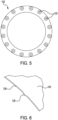
- the annular piece 102 as a series of holes 122 which may be used for bolts or other fasteners to couple the annular piece 102 to the aft section 98 ( Fig. 3 ).
- the annular piece 102 may have a series of protrusions 126 along its inner edge 128.
- the protrusions 126 may help maintain a desired configuration of the annular gap that serves as the annular nozzle 114, for example maintaining concentricity.
- the protrusions 126 protrude inward to maintain a desired spacing between the edge 128 and the inner nozzle insert 108 ( Fig. 3 ).
- the protrusions 126 may be evenly circumferentially spaced around the edge 128.
- the protrusions may have a height of about 0.25 mm (0.01 inch), as a non-limiting example.
- booster rocket configuration of a booster rocket that is capable of being installed around an object.
- Some alternative configurations are described below, and different sorts of manufacturing techniques may be used to produce the booster rocket 30, and alternative booster rocket configurations.
- the booster rocket 30 may have additional features not shown in the figures, for example having an igniter placed in an opening in the casing 40 at a suitable location for igniting the fuel (propellant) 44. Such additional features may be shown in one or more of the other embodiments shown below.
- the booster rocket 30 provides a low profile, without impacting the envelope of the flight vehicle 10 ( Fig. 1 ).
- the low profile means that the rocket booster 30 does not significantly impact the drag of the flight vehicle 10.
- the rocket 30 is retained without the flight vehicle 10 after use, and does not prevent use of the main propulsion device 16 ( Fig. 1 ), before, after, or during firing of the booster rocket 30.
- the rocket 30 may be configured to operate with a truncated aerospace nozzle configuration, which is compact and altitude compensating.
- Figs. 7 and 8 shows another embodiment, a rocket booster 230 that includes multiple nozzle pieces 232 circumferentially spaced (for example evenly circumferentially spaced) in a series of circular openings 234 on an aft surface of an annular casing 240 of the rocket booster 230.
- the nozzle pieces 232 define respective nozzles through which pressurized gasses pass from the interior of the annular casing 240, in which annular fuel 244 burns.
- the rocket booster 230 may be similar to the other rocket boosters (and variations) described elsewhere herewithin.
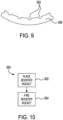
- Fig. 9 shows a cross-sectional shape of an annular fuel 260 that includes a series of longitudinal channels 262 to regulate the burn speed and thus the thrust production.
- Such channels may have any of a variety of suitable configurations (depths and/or shapes, for example), and there may be various numbers of channels, with any of various suitable spacings, to produce a desire thrust profile over time. It should be appreciated that the configuration shown in Fig. 7 is for illustration purposes, and the channels 262 shown are necessarily to scale.
- Fig. 10 shows a method 300 of use of a booster rocket, such as the booster rocket 30 ( Fig. 3 ) or the booster rocket 230 ( Fig. 7 ).
- the booster rocket is placed around a part of a flight vehicle, such as a nozzle of a main propulsion system, which may be a turbojet.
- propellant (fuel) of the booster rocket is burned used to provide additional thrust to the flight vehicle, before, after, or during operation of the main propulsion system.
- the booster rocket remains connected to the flight vehicle even after operation.
Landscapes
- Engineering & Computer Science (AREA)
- Chemical & Material Sciences (AREA)
- Combustion & Propulsion (AREA)
- General Engineering & Computer Science (AREA)
- Mechanical Engineering (AREA)
- Aviation & Aerospace Engineering (AREA)
- Remote Sensing (AREA)
- Toys (AREA)
Claims (15)
- Booster-Rakete (30), umfassend:ein ringförmiges Gehäuse (40, 240), das in seinem Inneren einen ringförmigen Raum (42) definiert und eine zentrale Öffnung (32) aufweist;einen festen Raketentreibstoff (44) in dem ringförmigen Raum (42); undein oder mehrere Düsenstücke (232), die mechanisch mit dem ringförmigen Gehäuse (40, 240) gekoppelt sind und eine oder mehrere Düsen an einem hinteren Ende des ringförmigen Gehäuses (40, 240) definieren, wobei das Gehäuse mehrere Gehäuseteile (60, 62) beinhaltet, undwobei die mehreren Gehäuseteile (60, 62) ein inneres Gehäuseteil und ein äußeres Gehäuseteil beinhalten; undwobei das innere Gehäuseteil und das äußere Gehäuseteil durch ein Gewinde miteinander gekoppelt sind.
- Booster-Rakete (30) nach Anspruch 1, wobei das eine oder die mehreren Düsenstücke (232) ein ringförmiges Düsenstück beinhalten, das eine ringförmige Düse definiert.
- Booster-Rakete (30) nach Anspruch 2, ferner umfassend eine Dichtung zwischen dem ringförmigen Düsenstück und dem ringförmigen Gehäuse (40, 240).
- Booster-Rakete (30) nach Anspruch 2 oder Anspruch 3, wobei das ringförmige Düsenstück die ringförmige Düse in Kombination mit einem inneren Düseneinsatz definiert, der an dem ringförmigen Gehäuse (40, 240) befestigt ist.
- Booster-Rakete (30) nach Anspruch 4, wobei das ringförmige Düsenstück und der innere Düseneinsatz zusammen einen Verengungseinsatz-Satz bilden.
- Booster-Rakete (30) nach Anspruch 2 oder einem der Ansprüche 2 bis 5, wobei das ringförmige Düsenstück Vorsprünge aufweist, die von einer Innenkante nach innen ragen, wobei die Vorsprünge das Aufrechterhalten eines ringförmigen Spalts der ringförmigen Düse ermöglichen.
- Booster-Rakete (30) nach Anspruch 2 oder einem der Ansprüche 2 bis 6, wobei das ringförmige Düsenstück aus einem metallischen Material hergestellt ist.
- Booster-Rakete (30) nach Anspruch 2 oder einem der Ansprüche 2 bis 6, wobei das ringförmige Düsenstück aus einem nichtmetallischen Material hergestellt ist.
- Booster-Rakete (30) nach Anspruch 2 oder einem der Ansprüche 2 bis 6, wobei das ringförmige Düsenstück aus einem Phenolmaterial hergestellt ist.
- Booster-Rakete (30) nach Anspruch 1, wobei das eine oder die mehreren Düsenstücke (232) mehrere Düsenstücke beinhalten.
- Booster-Rakete (30) nach Anspruch 10, wobei die mehreren Düsenstücke in Umfangsrichtung um das hintere Ende des ringförmigen Gehäuses (40, 240) herum beabstandet sind.
- Booster-Rakete (30) nach Anspruch 1 oder einem der Ansprüche 1 bis 11, ferner umfassend einen Zünder, der mit einer Außenfläche des ringförmigen Gehäuses (40, 240) gekoppelt ist, wobei der Zünder mit dem festen Raketentreibstoff (44) wirkgekoppelt ist, um die Einleitung der Verbrennung des festen Raketentreibstoffs (44) zu ermöglichen, ferner optional umfassend einen Zündbooster an einer Innenwand des ringförmigen Gehäuses (40, 240), wobei der Zündbooster mit dem Zünder und dem festen Raketentreibstoff (44) wirkgekoppelt ist, um die Einleitung der Verbrennung des festen Raketentreibstoffs (44) zu ermöglichen.
- Booster-Rakete (30) nach Anspruch 1 oder einem der Ansprüche 1 bis 12 in Kombination mit einem Objekt, mit dem der Raketenbooster mechanisch gekoppelt ist, wobei das Objekt optional ein hinterer Teil eines Fluggeräts ist oder wobei das Objekt optional Teil einer Antriebsvorrichtung an einem hinteren Ende des Fluggeräts ist.
- Kombination nach Anspruch 13, wobei das Fluggerät ein Flugkörper ist.
- Flugkörper, umfassendeinen Rumpf;ein Hauptantriebssystem, das eine Düse (22) beinhaltet, die nach hinten aus dem Rumpf herausragt; undeine Booster-Rakete (30) um die Düse herum, wobei die Booster-Rakete (30) Folgendes beinhaltet:ein ringförmiges Gehäuse (40, 240), das in seinem Inneren einen ringförmigen Raum (42) definiert und eine zentrale Öffnung (32) aufweist, durch die die Düse (22) ragt;einen festen Raketentreibstoff (44) in dem ringförmigen Raum (42); undein oder mehrere Düsenstücke (232), die mechanisch mit dem ringförmigen Gehäuse (40, 240) gekoppelt sind und eine oder mehrere Düsen an einem hinteren Ende des ringförmigen Gehäuses (40, 240) definieren, wobei das Gehäuse mehrere Gehäuseteile (60, 62) beinhaltet, undwobei die mehreren Gehäuseteile (60, 62) ein inneres Gehäuseteil und ein äußeres Gehäuseteil beinhalten; undwobei das innere Gehäuseteil und das äußere Gehäuseteil durch ein Gewinde miteinander gekoppelt sind.
Applications Claiming Priority (2)
| Application Number | Priority Date | Filing Date | Title |
|---|---|---|---|
| US17/181,162 US11732677B2 (en) | 2021-02-22 | 2021-02-22 | Ring-shaped booster rocket |
| PCT/US2021/038389 WO2022177594A1 (en) | 2021-02-22 | 2021-06-22 | Ring-shaped booster rocket |
Publications (2)
| Publication Number | Publication Date |
|---|---|
| EP4295027A1 EP4295027A1 (de) | 2023-12-27 |
| EP4295027B1 true EP4295027B1 (de) | 2024-11-20 |
Family
ID=78695775
Family Applications (1)
| Application Number | Title | Priority Date | Filing Date |
|---|---|---|---|
| EP21810768.8A Active EP4295027B1 (de) | 2021-02-22 | 2021-06-22 | Ringförmige booster-rakete |
Country Status (3)
| Country | Link |
|---|---|
| US (1) | US11732677B2 (de) |
| EP (1) | EP4295027B1 (de) |
| WO (1) | WO2022177594A1 (de) |
Families Citing this family (2)
| Publication number | Priority date | Publication date | Assignee | Title |
|---|---|---|---|---|
| USD1018428S1 (en) * | 2019-06-28 | 2024-03-19 | Christopher Craddock | Aerospike |
| USD1018427S1 (en) * | 2019-06-28 | 2024-03-19 | Christopher Craddock | Aerospike |
Family Cites Families (14)
| Publication number | Priority date | Publication date | Assignee | Title |
|---|---|---|---|---|
| US3118377A (en) | 1964-01-21 | Rocketwise propelled projectiles of the unguided type | ||
| US3167016A (en) * | 1956-07-30 | 1965-01-26 | Dehavilland Aircraft Canada | Rocket propelled missile |
| US3094072A (en) * | 1957-12-09 | 1963-06-18 | Arthur R Parilla | Aircraft, missiles, missile weapons systems, and space ships |
| US3305194A (en) * | 1960-03-08 | 1967-02-21 | Robert G Conard | Wind-insensitive missile |
| US3093964A (en) * | 1960-12-14 | 1963-06-18 | United Aircraft Corp | Two-stage rocket |
| US3434291A (en) * | 1967-04-04 | 1969-03-25 | Thiokol Chemical Corp | Thrust termination apparatus for solid propellant rocket motors |
| US3806064A (en) * | 1968-10-03 | 1974-04-23 | A Parilla | Missile configurations, controls and utilization techniques |
| DE3686321T2 (de) * | 1985-10-31 | 1992-12-17 | British Aerospace | Ausstossantrieb fuer flugkoerper. |
| US4964339A (en) | 1987-12-23 | 1990-10-23 | General Dynamics Corp., Pomona Division | Multiple stage rocket propelled missile system |
| FR2639404B1 (fr) * | 1988-11-21 | 1994-04-15 | Propulsion Ste Europeenne | Divergent de moteur-fusee a tuyere annulaire complementaire |
| US6968695B2 (en) | 2002-09-13 | 2005-11-29 | The Boeing Company | Compact lightweight ramjet engines incorporating swirl augmented combustion with improved performance |
| US20050211827A1 (en) | 2004-03-29 | 2005-09-29 | The Boeing Company | High speed missile wing and associated method |
| US20150204274A1 (en) * | 2014-01-21 | 2015-07-23 | Raytheon Company | Resin transfer molded rocket motor nozzle |
| KR101739391B1 (ko) * | 2017-01-18 | 2017-05-24 | 국방과학연구소 | 로켓 모터용 후방 점화기를 포함하는 발화장치 조립체 |
-
2021
- 2021-02-22 US US17/181,162 patent/US11732677B2/en active Active
- 2021-06-22 WO PCT/US2021/038389 patent/WO2022177594A1/en not_active Ceased
- 2021-06-22 EP EP21810768.8A patent/EP4295027B1/de active Active
Also Published As
| Publication number | Publication date |
|---|---|
| US11732677B2 (en) | 2023-08-22 |
| US20220268240A1 (en) | 2022-08-25 |
| EP4295027A1 (de) | 2023-12-27 |
| WO2022177594A1 (en) | 2022-08-25 |
Similar Documents
| Publication | Publication Date | Title |
|---|---|---|
| EP1685362B1 (de) | Geschoss mit mehreren nasenkegeln | |
| US4327886A (en) | Integral rocket ramjet missile | |
| US3901028A (en) | Ramjet with integrated rocket boost motor | |
| US20140150683A1 (en) | Gas generators, launch tubes including gas generators and related systems and methods | |
| EP4295027B1 (de) | Ringförmige booster-rakete | |
| US7762195B2 (en) | Slow cook off rocket igniter | |
| US4972673A (en) | Solid rocket motor with dual interrupted thrust | |
| US3491692A (en) | Multi-stage rocket | |
| EP3374723B1 (de) | Aerospike-raketentriebwerksanordnung | |
| KR101494393B1 (ko) | 이중 추력 로켓 추진기관 | |
| US4384454A (en) | Thrust nozzle for rocket engine with ablating lining | |
| US8117847B2 (en) | Hybrid missile propulsion system with reconfigurable multinozzle grid | |
| US2946261A (en) | Peripheral nozzle spinner rocket | |
| US7328571B2 (en) | Semi-axisymmetric scramjet flowpath with conformal nozzle | |
| US4154141A (en) | Ultrafast, linearly-deflagration ignition system | |
| US3313113A (en) | Control for opening nozzles of rocket engines | |
| US3403873A (en) | Guided missile | |
| US4327885A (en) | Thrust augmented rocket | |
| US5894723A (en) | Rocket engine nozzle with ejectable inserts | |
| US6481198B1 (en) | Multi-stage rocket motor assembly including jettisonable launch motor integrated with flight igniter | |
| EP4295026B1 (de) | Ringförmige booster-rakete | |
| US4495763A (en) | Dual-thrust nozzle apparatus for rockets | |
| US3430445A (en) | Combined rocket-ramjet aircraft | |
| RU2462686C2 (ru) | Способ увеличения дальности полета снаряда (варианты) и устройство для его реализации | |
| EP4232700B1 (de) | Integriertes antriebs- und gefechtskopfsystem für eine artillerierunde |
Legal Events
| Date | Code | Title | Description |
|---|---|---|---|
| STAA | Information on the status of an ep patent application or granted ep patent |
Free format text: STATUS: UNKNOWN |
|
| STAA | Information on the status of an ep patent application or granted ep patent |
Free format text: STATUS: THE INTERNATIONAL PUBLICATION HAS BEEN MADE |
|
| PUAI | Public reference made under article 153(3) epc to a published international application that has entered the european phase |
Free format text: ORIGINAL CODE: 0009012 |
|
| STAA | Information on the status of an ep patent application or granted ep patent |
Free format text: STATUS: REQUEST FOR EXAMINATION WAS MADE |
|
| 17P | Request for examination filed |
Effective date: 20230918 |
|
| AK | Designated contracting states |
Kind code of ref document: A1 Designated state(s): AL AT BE BG CH CY CZ DE DK EE ES FI FR GB GR HR HU IE IS IT LI LT LU LV MC MK MT NL NO PL PT RO RS SE SI SK SM TR |
|
| DAV | Request for validation of the european patent (deleted) | ||
| DAX | Request for extension of the european patent (deleted) | ||
| REG | Reference to a national code |
Ref country code: DE Ipc: F02K0009080000 Ref country code: DE Ref legal event code: R079 Ref document number: 602021022176 Country of ref document: DE Free format text: PREVIOUS MAIN CLASS: F02K0009100000 Ipc: F02K0009080000 |
|
| GRAP | Despatch of communication of intention to grant a patent |
Free format text: ORIGINAL CODE: EPIDOSNIGR1 |
|
| STAA | Information on the status of an ep patent application or granted ep patent |
Free format text: STATUS: GRANT OF PATENT IS INTENDED |
|
| RIC1 | Information provided on ipc code assigned before grant |
Ipc: F02K 9/08 20060101AFI20240621BHEP |
|
| RAP3 | Party data changed (applicant data changed or rights of an application transferred) |
Owner name: RAYTHEON COMPANY |
|
| INTG | Intention to grant announced |
Effective date: 20240726 |
|
| GRAS | Grant fee paid |
Free format text: ORIGINAL CODE: EPIDOSNIGR3 |
|
| GRAA | (expected) grant |
Free format text: ORIGINAL CODE: 0009210 |
|
| STAA | Information on the status of an ep patent application or granted ep patent |
Free format text: STATUS: THE PATENT HAS BEEN GRANTED |
|
| AK | Designated contracting states |
Kind code of ref document: B1 Designated state(s): AL AT BE BG CH CY CZ DE DK EE ES FI FR GB GR HR HU IE IS IT LI LT LU LV MC MK MT NL NO PL PT RO RS SE SI SK SM TR |
|
| REG | Reference to a national code |
Ref country code: GB Ref legal event code: FG4D |
|
| REG | Reference to a national code |
Ref country code: CH Ref legal event code: EP |
|
| REG | Reference to a national code |
Ref country code: DE Ref legal event code: R096 Ref document number: 602021022176 Country of ref document: DE |
|
| REG | Reference to a national code |
Ref country code: IE Ref legal event code: FG4D |
|
| REG | Reference to a national code |
Ref country code: LT Ref legal event code: MG9D |
|
| REG | Reference to a national code |
Ref country code: NL Ref legal event code: MP Effective date: 20241120 |
|
| PG25 | Lapsed in a contracting state [announced via postgrant information from national office to epo] |
Ref country code: IS Free format text: LAPSE BECAUSE OF FAILURE TO SUBMIT A TRANSLATION OF THE DESCRIPTION OR TO PAY THE FEE WITHIN THE PRESCRIBED TIME-LIMIT Effective date: 20250320 Ref country code: PT Free format text: LAPSE BECAUSE OF FAILURE TO SUBMIT A TRANSLATION OF THE DESCRIPTION OR TO PAY THE FEE WITHIN THE PRESCRIBED TIME-LIMIT Effective date: 20250320 Ref country code: HR Free format text: LAPSE BECAUSE OF FAILURE TO SUBMIT A TRANSLATION OF THE DESCRIPTION OR TO PAY THE FEE WITHIN THE PRESCRIBED TIME-LIMIT Effective date: 20241120 |
|
| PG25 | Lapsed in a contracting state [announced via postgrant information from national office to epo] |
Ref country code: FI Free format text: LAPSE BECAUSE OF FAILURE TO SUBMIT A TRANSLATION OF THE DESCRIPTION OR TO PAY THE FEE WITHIN THE PRESCRIBED TIME-LIMIT Effective date: 20241120 Ref country code: NL Free format text: LAPSE BECAUSE OF FAILURE TO SUBMIT A TRANSLATION OF THE DESCRIPTION OR TO PAY THE FEE WITHIN THE PRESCRIBED TIME-LIMIT Effective date: 20241120 |
|
| REG | Reference to a national code |
Ref country code: AT Ref legal event code: MK05 Ref document number: 1743786 Country of ref document: AT Kind code of ref document: T Effective date: 20241120 |
|
| PG25 | Lapsed in a contracting state [announced via postgrant information from national office to epo] |
Ref country code: BG Free format text: LAPSE BECAUSE OF FAILURE TO SUBMIT A TRANSLATION OF THE DESCRIPTION OR TO PAY THE FEE WITHIN THE PRESCRIBED TIME-LIMIT Effective date: 20241120 |
|
| PG25 | Lapsed in a contracting state [announced via postgrant information from national office to epo] |
Ref country code: ES Free format text: LAPSE BECAUSE OF FAILURE TO SUBMIT A TRANSLATION OF THE DESCRIPTION OR TO PAY THE FEE WITHIN THE PRESCRIBED TIME-LIMIT Effective date: 20241120 |
|
| PG25 | Lapsed in a contracting state [announced via postgrant information from national office to epo] |
Ref country code: NO Free format text: LAPSE BECAUSE OF FAILURE TO SUBMIT A TRANSLATION OF THE DESCRIPTION OR TO PAY THE FEE WITHIN THE PRESCRIBED TIME-LIMIT Effective date: 20250220 |
|
| PG25 | Lapsed in a contracting state [announced via postgrant information from national office to epo] |
Ref country code: LV Free format text: LAPSE BECAUSE OF FAILURE TO SUBMIT A TRANSLATION OF THE DESCRIPTION OR TO PAY THE FEE WITHIN THE PRESCRIBED TIME-LIMIT Effective date: 20241120 Ref country code: GR Free format text: LAPSE BECAUSE OF FAILURE TO SUBMIT A TRANSLATION OF THE DESCRIPTION OR TO PAY THE FEE WITHIN THE PRESCRIBED TIME-LIMIT Effective date: 20250221 Ref country code: AT Free format text: LAPSE BECAUSE OF FAILURE TO SUBMIT A TRANSLATION OF THE DESCRIPTION OR TO PAY THE FEE WITHIN THE PRESCRIBED TIME-LIMIT Effective date: 20241120 |
|
| PG25 | Lapsed in a contracting state [announced via postgrant information from national office to epo] |
Ref country code: PL Free format text: LAPSE BECAUSE OF FAILURE TO SUBMIT A TRANSLATION OF THE DESCRIPTION OR TO PAY THE FEE WITHIN THE PRESCRIBED TIME-LIMIT Effective date: 20241120 |
|
| PG25 | Lapsed in a contracting state [announced via postgrant information from national office to epo] |
Ref country code: RS Free format text: LAPSE BECAUSE OF FAILURE TO SUBMIT A TRANSLATION OF THE DESCRIPTION OR TO PAY THE FEE WITHIN THE PRESCRIBED TIME-LIMIT Effective date: 20250220 |
|
| PG25 | Lapsed in a contracting state [announced via postgrant information from national office to epo] |
Ref country code: SM Free format text: LAPSE BECAUSE OF FAILURE TO SUBMIT A TRANSLATION OF THE DESCRIPTION OR TO PAY THE FEE WITHIN THE PRESCRIBED TIME-LIMIT Effective date: 20241120 |
|
| PGFP | Annual fee paid to national office [announced via postgrant information from national office to epo] |
Ref country code: DE Payment date: 20250520 Year of fee payment: 5 |
|
| PG25 | Lapsed in a contracting state [announced via postgrant information from national office to epo] |
Ref country code: DK Free format text: LAPSE BECAUSE OF FAILURE TO SUBMIT A TRANSLATION OF THE DESCRIPTION OR TO PAY THE FEE WITHIN THE PRESCRIBED TIME-LIMIT Effective date: 20241120 |
|
| PGFP | Annual fee paid to national office [announced via postgrant information from national office to epo] |
Ref country code: GB Payment date: 20250520 Year of fee payment: 5 |
|
| PG25 | Lapsed in a contracting state [announced via postgrant information from national office to epo] |
Ref country code: EE Free format text: LAPSE BECAUSE OF FAILURE TO SUBMIT A TRANSLATION OF THE DESCRIPTION OR TO PAY THE FEE WITHIN THE PRESCRIBED TIME-LIMIT Effective date: 20241120 |
|
| PGFP | Annual fee paid to national office [announced via postgrant information from national office to epo] |
Ref country code: FR Payment date: 20250520 Year of fee payment: 5 |
|
| PG25 | Lapsed in a contracting state [announced via postgrant information from national office to epo] |
Ref country code: RO Free format text: LAPSE BECAUSE OF FAILURE TO SUBMIT A TRANSLATION OF THE DESCRIPTION OR TO PAY THE FEE WITHIN THE PRESCRIBED TIME-LIMIT Effective date: 20241120 |
|
| PG25 | Lapsed in a contracting state [announced via postgrant information from national office to epo] |
Ref country code: SK Free format text: LAPSE BECAUSE OF FAILURE TO SUBMIT A TRANSLATION OF THE DESCRIPTION OR TO PAY THE FEE WITHIN THE PRESCRIBED TIME-LIMIT Effective date: 20241120 |
|
| PG25 | Lapsed in a contracting state [announced via postgrant information from national office to epo] |
Ref country code: CZ Free format text: LAPSE BECAUSE OF FAILURE TO SUBMIT A TRANSLATION OF THE DESCRIPTION OR TO PAY THE FEE WITHIN THE PRESCRIBED TIME-LIMIT Effective date: 20241120 |
|
| PG25 | Lapsed in a contracting state [announced via postgrant information from national office to epo] |
Ref country code: IT Free format text: LAPSE BECAUSE OF FAILURE TO SUBMIT A TRANSLATION OF THE DESCRIPTION OR TO PAY THE FEE WITHIN THE PRESCRIBED TIME-LIMIT Effective date: 20241120 |
|
| REG | Reference to a national code |
Ref country code: DE Ref legal event code: R097 Ref document number: 602021022176 Country of ref document: DE |
|
| PG25 | Lapsed in a contracting state [announced via postgrant information from national office to epo] |
Ref country code: SE Free format text: LAPSE BECAUSE OF FAILURE TO SUBMIT A TRANSLATION OF THE DESCRIPTION OR TO PAY THE FEE WITHIN THE PRESCRIBED TIME-LIMIT Effective date: 20241120 |
|
| PLBE | No opposition filed within time limit |
Free format text: ORIGINAL CODE: 0009261 |
|
| STAA | Information on the status of an ep patent application or granted ep patent |
Free format text: STATUS: NO OPPOSITION FILED WITHIN TIME LIMIT |
|
| 26N | No opposition filed |
Effective date: 20250821 |
|
| REG | Reference to a national code |
Ref country code: CH Ref legal event code: H13 Free format text: ST27 STATUS EVENT CODE: U-0-0-H10-H13 (AS PROVIDED BY THE NATIONAL OFFICE) Effective date: 20260127 |
|
| PG25 | Lapsed in a contracting state [announced via postgrant information from national office to epo] |
Ref country code: MC Free format text: LAPSE BECAUSE OF FAILURE TO SUBMIT A TRANSLATION OF THE DESCRIPTION OR TO PAY THE FEE WITHIN THE PRESCRIBED TIME-LIMIT Effective date: 20241120 |
|
| PG25 | Lapsed in a contracting state [announced via postgrant information from national office to epo] |
Ref country code: LU Free format text: LAPSE BECAUSE OF NON-PAYMENT OF DUE FEES Effective date: 20250622 |
|
| REG | Reference to a national code |
Ref country code: BE Ref legal event code: MM Effective date: 20250630 |
|
| PG25 | Lapsed in a contracting state [announced via postgrant information from national office to epo] |
Ref country code: IE Free format text: LAPSE BECAUSE OF NON-PAYMENT OF DUE FEES Effective date: 20250622 |
|
| PG25 | Lapsed in a contracting state [announced via postgrant information from national office to epo] |
Ref country code: BE Free format text: LAPSE BECAUSE OF NON-PAYMENT OF DUE FEES Effective date: 20250630 |