EP4293923A1 - Timing detection device and timing detection method - Google Patents
Timing detection device and timing detection method Download PDFInfo
- Publication number
- EP4293923A1 EP4293923A1 EP22752492.3A EP22752492A EP4293923A1 EP 4293923 A1 EP4293923 A1 EP 4293923A1 EP 22752492 A EP22752492 A EP 22752492A EP 4293923 A1 EP4293923 A1 EP 4293923A1
- Authority
- EP
- European Patent Office
- Prior art keywords
- code
- correlation
- reference code
- module
- timing detection
- Prior art date
- Legal status (The legal status is an assumption and is not a legal conclusion. Google has not performed a legal analysis and makes no representation as to the accuracy of the status listed.)
- Granted
Links
Images




Classifications
-
- H—ELECTRICITY
- H04—ELECTRIC COMMUNICATION TECHNIQUE
- H04L—TRANSMISSION OF DIGITAL INFORMATION, e.g. TELEGRAPHIC COMMUNICATION
- H04L7/00—Arrangements for synchronising receiver with transmitter
- H04L7/04—Speed or phase control by synchronisation signals
- H04L7/041—Speed or phase control by synchronisation signals using special codes as synchronising signal
- H04L7/042—Detectors therefor, e.g. correlators, state machines
-
- H—ELECTRICITY
- H04—ELECTRIC COMMUNICATION TECHNIQUE
- H04L—TRANSMISSION OF DIGITAL INFORMATION, e.g. TELEGRAPHIC COMMUNICATION
- H04L7/00—Arrangements for synchronising receiver with transmitter
- H04L7/04—Speed or phase control by synchronisation signals
-
- H—ELECTRICITY
- H04—ELECTRIC COMMUNICATION TECHNIQUE
- H04B—TRANSMISSION
- H04B1/00—Details of transmission systems, not covered by a single one of groups H04B3/00 - H04B13/00; Details of transmission systems not characterised by the medium used for transmission
- H04B1/69—Spread spectrum techniques
- H04B1/707—Spread spectrum techniques using direct sequence modulation
- H04B1/7073—Synchronisation aspects
-
- H—ELECTRICITY
- H04—ELECTRIC COMMUNICATION TECHNIQUE
- H04J—MULTIPLEX COMMUNICATION
- H04J13/00—Code division multiplex systems
- H04J13/0007—Code type
- H04J13/0011—Complementary
Definitions
- the present disclosure generally relates to time detection techniques and, more particularly relates, to devices and methods for detecting timing upon receiving a digitally modulated signal.
- Patent Document 1 describes a wireless communication method and apparatus for receiving a signal modulated with a barker code.
- Patent document 1 Japanese Patent Laid-Open No. 2005 -311532
- the timing detection device includes a main reference code generation module, an auxiliary reference code generation module, a first correlation processing module, a second correlation processing module, and a subtraction module.
- the main reference code generation module is configured to generate a main reference code consisting of the same code as a code for synchronization included in a received signal.
- the auxiliary reference code generation module by using a portion of the same code as the code for synchronization, is configured to generate an auxiliary reference code consisting of a code configuration different from the main reference code and suppressing the generation of a main lobe during a correlation process.
- the first correlation processing module is configured to output a first correlation result by correlating the received signal with the main reference code.
- the second correlation processing module is configured to output a second correlation result by correlating the received signal with the auxiliary reference code.
- the subtraction module is configured to subtract the first correlation result from the second correlation result.
- the side lobe of the first correlation result and the side lobe of the second correlation result are offset in the output of the subtraction module.
- the sidelobe during correlation processing can be suppressed.
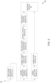
- FIG. 1 is a functional block diagram of a timing detection device 52 (hereinafter also interchangeably referred to as a "correlation module 52") according to an embodiment of the present invention.
- FIG. 2 is a functional block diagram of the AIS device according to the embodiment of the present invention.
- FIG. 2 is a functional block diagram of the AIS device 10 according to an embodiment of the present invention.
- the AIS device 10 includes an antenna 20, a first down conversion module 30, a coarse frequency control module 41, a symbol timing detection module 42, a second down conversion module 43, a phase control module 44, a frequency tracking module 45, a signal detection module 51, a correlation module 52, and a decoding module 60.
- the modules of the AIS device 10 except the antenna 20 can be realized by an analog circuit, a digital circuit, an arithmetic processing unit such as a computer, etc.
- the antenna 20 receives the signal for an AIS and outputs the received signal to the first down conversion module 30.
- the first down conversion module 30 down-converts the received signal to a frequency (for example, 10 times the frequency) that is a predetermined multiple of the baseband signal.
- the first down conversion module 30 outputs the down-converted received signal to the coarse frequency control module 41 and the signal detection module 51.
- FIG. 3 illustrates an example data configuration of a signal for the AIS 10 for the ship, in accordance with an embodiment of the present invention.
- the signal for automatic identification of ships is composed of RU data, SW data, Link Config Identity (LCID) data, DS data, Ramp-Down (RD) data, and Guard time Data (GD).
- RU data RU data
- SW data SW data
- Link Config Identity (LCID) data DS data
- RD Ramp-Down
- GD Guard time Data
- the signal is arranged in the order of RU data, SW data, LCID data, DS data, RD data, and GD data.
- Each of the RU data, the SW data, the LCID data, the DS data, and the RD has a prescribed number of bits, and each is modulated by a prescribed modulation method.
- the prescribed modulation method may include but is not limited to Quadrature Phase Shift Keying (QPSK), 8 Phase-Shift Keying (PSK), 16 Quadrature amplitude modulation (QAM), etc.
- RU data represents a beginning of data of the AIS ([Universal Shipborne] Automatic Identification System) signal.
- SW data is for timing detection and frequency control.
- LCID data represents a modulation method of DS data.
- DS data includes various information for the AIS 10 such as ship identification ID.
- RD data is for AIS signals, more specifically, data representing the end of DS data.
- the GD is a time interval left vacant, having no signal or data, during which no data is sent.
- the SW data corresponds to a "preamble" of the received signal.
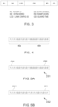
- FIG. 4 shows an example of a bit array of the SW data.
- the SW data is composed of a non-inversion code 402 and an inversion code 404.
- the SW data is a sequence code of a non-inversion code and an inversion code.
- the inversion code 404 is a code obtained by inverting the non-inversion code 402.
- non-inversion code is "1, 1, 1, 1, 1, 0, 0, 1, 0, 0, 1, 0, 0, 1, 0, 0, 0, 1, 0, 0, 0, 0."
- SW data is "1, 1, 1, 1, 1, 1, 0, 0, 1, 1, 0, 1, 0, 0, 0, 0, 1, 1, 0, 0, 1, 0, 1, 0, 1, 0, 1, 0, 1, 0, 1, 0, 1, 0, 1, 0, 1, 0, 1, 0, 1, 0."
- the coarse frequency control module 41 estimates and calculates the frequency deviation from the received signal to perform coarse frequency control.
- the frequency of the reference signal is driven from a range of +/- 500 Hz to a range of +/- 30 Hz relative to the frequency of the received signal.
- the symbol timing detection module 42 detects symbol timing for the received signal after the coarse control output from the coarse frequency control module 41.
- the second down conversion module 43 down-converts the output signal of the symbol timing detection module 42 to the baseband frequency.
- the phase control module 44 performs automatic phase control on the signal down-converted to the baseband (baseband signal).
- the frequency tracking module 45 performs automatic phase control and automatic frequency control with higher accuracy on the baseband signal output from the phase control module 44. This forces the frequency of the reference signal from a range of +/- 500 Hz to a range of +/- 30 Hz relative to the frequency of the received signal. Therefore, convergence to the desired symbol point can be achieved with high accuracy.
- the frequency tracking module 45 outputs the signal (demodulated signal) after the automatic phase control and the automatic frequency control to the decoding module 60.
- the signal detection module 51 detects the RU data of the received signal.
- the correlation module 52 uses the timing of the RU data to perform correlation processing between the received signal and the reference code. The specific configuration and processing of the correlation module 52 will be described later.
- the correlation module 52 outputs the correlation processing result to the decoding module 60.
- the correlation processing result output from the correlation module 52 has a main lobe corresponding to the slot timing of the received signal. Therefore, the correlation result (output correlation result) output from the correlation module 52 enables the detection of the slot timing of the received signal. That is, the correlation module 52 corresponds to the "timing detection device 52" of the present invention.
- the decoding module 60 decodes data including various information for an AIS such as a ship identification ID from the DS (Data Symbol) data.
- the correlation module 52 includes a correlation processing module 521, a correlation processing module 522, a subtraction module 523, a VCO 524, a main reference code generation module 525, and an auxiliary reference code generation module 526.
- the correlation processing module 521 corresponds to the "first correlation processing module” of the present invention
- the correlation processing module 522 corresponds to the "second correlation processing module” of the present invention.
- the VCO 524 generates a reference frequency signal for correlation processing.
- the VCO 524 outputs the reference frequency signal to a main reference code generation module 525 and an auxiliary reference code generation module 526.
- FIG. 5A is a diagram showing an example of the bit arrangement of a main reference code C51 in accordance with a first embodiment of the present invention
- FIG. 5B is a diagram showing an example of the bit arrangement of an auxiliary reference code C52 in accordance with the first embodiment of the present invention.
- the main reference code generation module 525 generates the main reference code using the reference frequency signal.
- the main reference code generation module 525 outputs the generated main reference code C51 to the correlation processing module 521.
- the main reference code C51 is a sequence code of a first code sequence C511 and a second code sequence C512.
- the first code sequence C511 is the same code as the non-inversion code of SW data.
- the second code sequence C512 is the same code as the inversion code of SW data.
- the first code sequence C511 is "1, 1, 1, 1, 1, 1, 0, 0, 1, 0, 1, 0, 1, 0, 1"
- the second code sequence C512 is "0, 0, 0, 0, 0, 1, 0, 0, 0, 0." Therefore, the main reference code C51 is "1, 1, 1, 1, 1, 1, 0, 0, 1, 1, 0, 1, 0, 0, 0, 0, 1, 1, 0, 0, 1, 0, 1, 0, 1, 0, 1, 0, 1, 0, 1, 0 1, 0" and is the same code as SW data.
- the auxiliary reference code generation module 526 generates the auxiliary reference code C52 using a reference frequency signal.
- the auxiliary reference code generation module 526 outputs the generated auxiliary reference code C52 to the correlation processing module 522.
- the auxiliary reference code C52 is a sequence code of the first code sequence C511.
- the first code sequence C511 is the same code as the non-inversion code of the SW data.
- the first code sequence C511 is "1,1,1,1,1,1,0,0,1,1,0,1.” Therefore, the auxiliary reference code C52 is "1, 1, 1, 1, 1, 1, 0, 0, 1, 1, 1, 1, 1, 1, 1, 1, 1, 1, 1, 0, 0, 1, 1, 0, 1, 0, 1, 0, 1.” That is, the auxiliary reference code C52 is constructed using a portion of the SW data, and more specifically, a non-inversion code of the SW data.
- the correlation processing module 521 performs correlation processing between the received signal and the main reference code, and outputs the absolute value data of the first correlation result (first correlation data) to the subtraction module 523.
- the correlation processing module 522 performs correlation processing between the received signal and the auxiliary reference code, and outputs the absolute value data of the second correlation result (second correlation data) to the subtraction module 523
- the subtraction module 523 differentiates the absolute value data of the first correlation result (first correlation data) from the absolute value data of the second correlation result (second correlation data), and outputs the final correlation result (final correlation data).
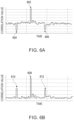
- FIG. 6A and FIG. 6B show the correlation result (first correlation result) between the SW data and the main reference code C51
- FIG. 6C and FIG. 6D show the correlation result (second correlation result) between the SW data and the auxiliary reference code C52
- FIG. 6B shows the absolute value data of FIG. 6A
- FIG. 6D shows the absolute value data of FIG. 6C .
- the first correlation result in which the correlation is performed using the main reference code having the same code structure as the SW data, generates a sidelobe of a prescribed level together with the main lobe.
- the second correlation result (second correlation data), in which the correlation is performed using the auxiliary reference code having the above code structure, generates only a sidelobe as shown in FIG. 6C and FIG. 6D .
- the main reference code and the auxiliary reference code have the above code structure, the position of the side lobe (position on the time axis) of the correlation (first correlation result (first correlation data)) using the main reference code and the position of the side lobe (position on the time axis) of the correlation (second correlation result (second correlation data)) using the auxiliary reference code become the same.
- the subtraction module 523 performs a difference operation between the first correlation result (first correlation data) and the second correlation result (second correlation data), the side lobes are canceled and suppressed, and only the main lobe remains.
- FIG. 7 shows the final correlation result (final correlation data). As shown in FIG. 7 , the final correlation result (final correlation data) has almost no side lobe and the main lobe remains.
- the correlation module 52 (or the timing detection device) can suppress the side lobe during correlation processing.
- the AIS device 10 can perform synchronization with high accuracy.
- the AIS device 10 can also perform frequency control with high accuracy.
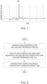
- FIG. 8 is a flowchart showing an example of a timing detection method according to an embodiment of the present invention.
- each module described by the explanation of the above configuration is omitted from the description below.
- the correlation module 52 generates the main reference code C51, and the auxiliary reference code C52.
- the correlation module 52 executes the first correlation using the main reference code C51 and the second correlation using the auxiliary reference code C52.
- the correlation module 52 differentiates the first correlation result from the second correlation result.
- FIG. 9A is a diagram showing an example of the bit arrangement of the main reference code C51 according to the second embodiment of the present invention
- FIG. 9B is a diagram showing an example of the bit arrangement of an auxiliary reference code C52A according to the second embodiment of the present invention
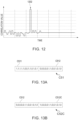
- FIG. 10A and FIG. 10B are diagrams showing the correlation result (second correlation result) between SW data and the auxiliary reference code C52A.
- FIG. 10B is the absolute value data in FIG. 10A .
- the timing detection technique of the second embodiment differs in the auxiliary reference code from the timing detection technique of the first embodiment.
- Other contents of the timing detection technique of the second embodiment are the same as those of the timing detection technique of the first embodiment, and each description of the same modules is omitted.
- the correlation module 52 generates a code in which the first code sequence C511 and the second code sequence C512 continue as the main reference code C51. Therefore, the main reference code C51 is the same code as the SW data. The correlation module 52 uses the main reference code C51 to execute the first correlation.
- the correlation module 52 generates a code in which the second code sequence C512 continues as the auxiliary reference code C52A.
- the auxiliary reference code C52A is "0, 0, 0, 0, 0, 1, 1, 0, 0, 1, 0, 0, 0, 0, 0, 0, 0, 0, 1, 1, 0, 0, 1, 0, 1, 0, 1, 0, 1, 0, 1, 0, 1, 0."
- the correlation module 52 executes the second correlation using the auxiliary reference code C52A.
- the main lobe is suppressed and the side lobe is generated without suppression.
- the side lobe can be suppressed in the final correlation result (the final correlation data).
- FIG. 11A is a diagram showing an example of the bit arrangement of the main reference code C51 according to the third embodiment
- FIG. 11B is a diagram showing an example of the bit arrangement of the auxiliary reference code C52B according to the third embodiment of the present invention
- FIG. 12 is a diagram showing the final correlation result (final correlation data) according to the third embodiment.
- the timing detection technique according to the third embodiment differs from the timing detection technique according to the second embodiment in the auxiliary reference code.
- the other contents of the timing detection technique according to the third embodiment are the same as those of the timing detection technique according to the second embodiment, and each description of the same modules is omitted.
- the correlation module 52 generates a code in which the first code sequence C511 and the second code sequence C512 continue as the main reference code C51. Therefore, the main reference code C51 is the same code as the SW data. The correlation module 52 executes the first correlation using the main reference code C51.
- the second code sequence C512 and the third code sequence C512B sequentially generate codes.
- the third code sequence C512B is a code in which some bits of the second code sequence C512 are different. More specifically, the third code sequence C512B is a code in which the last bit of the second code sequence C512 is reversed.
- the third code sequence C512B is "0, 0, 0, 0, 0, 1, 0, 0, 1, 1.” Therefore, the auxiliary reference code C52B is "0,0,0,0,0,0,0,0,1,0,0,0,0,0,0,0,0,0,0,0,0,0,0,0,0,0,0,0,0,0,0,0,0,0,0,0,0,0,0,0,0,0,0,0,0,0,0,0,0,0,0,0,0,0,0,0,1,0,0,0,0,1,0,1,1.”
- the correlation module 52 executes the second correlation using the auxiliary reference code C52B.
- auxiliary reference code C52B By using such auxiliary reference code C52B, as in the second embodiment, the main lobe is suppressed and the side lobe is generated with little suppression.
- the main lobe is not suppressed and the side lobe can be suppressed.
- FIG. 13A is a diagram showing an example of the bit arrangement of the main reference code according to the fourth embodiment
- FIG. 13B is a diagram showing an example of the bit arrangement of an auxiliary reference code according to the fourth embodiment.
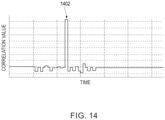
- FIG. 14 is a diagram showing the final correlation result (final correlation data) according to the fourth embodiment.
- the timing detection technique of the fourth embodiment differs in the auxiliary reference code from the timing detection technique of the second embodiment.
- Other contents of the timing detection technique of the fourth embodiment are the same as those of the timing detection technique of the second embodiment, and each description of the same modules is omitted.
- the correlation module 52 generates a code in which the first code sequence C511 and the second code sequence C512 continue as the main reference code C51. Therefore, the main reference code C51 is the same code as the SW data. The correlation module 52 uses the main reference code C51 to execute the first correlation.
- the second code sequence C512 and a fourth code sequence C512C sequentially generate codes.
- the fourth code sequence C512C is a code in which some bits of the second code sequence C512 are different. More specifically, the fourth code sequence C512C is a code in which the first bit of the second code sequence C512 is reversed.
- the fourth code sequence C512C is "1, 0, 0, 0, 0, 1, 1, 0, 0, 1, 0." Therefore, the auxiliary reference code C52B is "0, 0, 0, 0, 0, 1, 1, 0, 0, 1, 0, 1, 0, 1, 0, 1, 0, 0, 0, 1, 1, 0, 0, 1, 0, 1, 0, 1, 0, 1, 0, 1, 0, 0."
- the correlation module 52 executes the second correlation using the auxiliary reference code C52C.
- the main lobe is not suppressed and the side lobe can be suppressed.
Landscapes
- Engineering & Computer Science (AREA)
- Computer Networks & Wireless Communication (AREA)
- Signal Processing (AREA)
- Synchronisation In Digital Transmission Systems (AREA)
- Radar Systems Or Details Thereof (AREA)
Abstract
Description
- The present disclosure generally relates to time detection techniques and, more particularly relates, to devices and methods for detecting timing upon receiving a digitally modulated signal.
-
Patent Document 1 describes a wireless communication method and apparatus for receiving a signal modulated with a barker code. - Patent document 1:
Japanese Patent Laid-Open No. 2005 -311532 - However, in the above prior art, when the correlation is performed using a spread code such as a conventional barker code and a predetermined timing such as a slot timing is detected, a relatively large side lobe occurs in the correlation result. This may cause an error in the detected timing.
- Therefore, a need exists to suppress the side lobe during correlation processing.
- The timing detection device includes a main reference code generation module, an auxiliary reference code generation module, a first correlation processing module, a second correlation processing module, and a subtraction module. The main reference code generation module is configured to generate a main reference code consisting of the same code as a code for synchronization included in a received signal. The auxiliary reference code generation module, by using a portion of the same code as the code for synchronization, is configured to generate an auxiliary reference code consisting of a code configuration different from the main reference code and suppressing the generation of a main lobe during a correlation process. The first correlation processing module is configured to output a first correlation result by correlating the received signal with the main reference code. The second correlation processing module is configured to output a second correlation result by correlating the received signal with the auxiliary reference code. The subtraction module is configured to subtract the first correlation result from the second correlation result.
- In this configuration, the side lobe of the first correlation result and the side lobe of the second correlation result are offset in the output of the subtraction module.
- According to the invention, the sidelobe during correlation processing can be suppressed.
-
-
FIG. 1 illustrates a functional block diagram of a timing detection device, in accordance with an embodiment of the present disclosure; -
FIG. 2 illustrates a functional block diagram of an Automatic Identification System (AIS) for a ship, in accordance with an embodiment of the present disclosure; -
FIG. 3 illustrates an example data configuration of a signal for the AIS, in accordance with an embodiment of the present disclosure; -
FIG. 4 illustrates a bit array of Syncword (SW) data, in accordance with an embodiment of the present disclosure; -
FIG. 5A illustrates an example of a bit arrangement of a main reference code, in accordance with a first embodiment of the present disclosure; -
FIG. 5B is a diagram showing an example of a bit arrangement of an auxiliary reference code, in accordance with the first embodiment of the present disclosure; -
FIG. 6A and FIG. 6B are diagrams showing the correlation result (first correlation result) between SW data and the main reference code, in accordance with the first embodiment of the present disclosure; -
FIG. 6C and FIG. 6D are diagrams showing the correlation result (second correlation result) between the SW data and the auxiliary reference code, in accordance with the first embodiment of the present disclosure; -
FIG. 7 is a diagram showing the final correlation result (final correlation data), in accordance with the first embodiment of the present disclosure; -
FIG. 8 is a flowchart showing an example of a timing detection method, in accordance with an embodiment of the present disclosure; -
FIG. 9A shows an example of a bit arrangement of the main reference code, in accordance with a second embodiment of the present disclosure; -
FIG. 9B shows an example of a bit arrangement of the auxiliary reference code, in accordance with the second embodiment of the present disclosure; -
FIG. 10A andFIG. 10B show the correlation result (second correlation result) between the SW data and the auxiliary reference code, in accordance with the second embodiment of the present disclosure; -
FIG. 11A shows an example of a bit arrangement of the main reference code according to a third embodiment, in accordance with a third embodiment of the present disclosure; -
FIG. 11B shows an example of a bit arrangement of the auxiliary reference code according to the third embodiment, in accordance with the third embodiment of the present disclosure; -
FIG. 12 shows the final correlation result (final correlation data), in accordance with the third embodiment of the present disclosure; -
FIG. 13A shows an example of a bit arrangement of the main reference code, in accordance with a fourth embodiment of the present disclosure; -
FIG. 13B shows an example of a bit arrangement of the auxiliary reference code, in accordance with the fourth embodiment of the present disclosure; and -
FIG. 14 shows the final correlation result (final correlation data), in accordance with the fourth embodiment of the present disclosure. - A timing detection technique according to a first embodiment of the present invention will be described with reference to the figures.
FIG. 1 is a functional block diagram of a timing detection device 52 (hereinafter also interchangeably referred to as a "correlation module 52") according to an embodiment of the present invention.FIG. 2 is a functional block diagram of the AIS device according to the embodiment of the present invention. -
FIG. 2 is a functional block diagram of theAIS device 10 according to an embodiment of the present invention. As shown inFIG. 2 , theAIS device 10 includes anantenna 20, a firstdown conversion module 30, a coarsefrequency control module 41, a symboltiming detection module 42, a seconddown conversion module 43, aphase control module 44, afrequency tracking module 45, asignal detection module 51, acorrelation module 52, and adecoding module 60. The modules of theAIS device 10 except theantenna 20 can be realized by an analog circuit, a digital circuit, an arithmetic processing unit such as a computer, etc. - The
antenna 20 receives the signal for an AIS and outputs the received signal to the firstdown conversion module 30. The firstdown conversion module 30 down-converts the received signal to a frequency (for example, 10 times the frequency) that is a predetermined multiple of the baseband signal. The firstdown conversion module 30 outputs the down-converted received signal to the coarsefrequency control module 41 and thesignal detection module 51. -
FIG. 3 illustrates an example data configuration of a signal for theAIS 10 for the ship, in accordance with an embodiment of the present invention. The signal for automatic identification of ships is composed of RU data, SW data, Link Config Identity (LCID) data, DS data, Ramp-Down (RD) data, and Guard time Data (GD). - The signal is arranged in the order of RU data, SW data, LCID data, DS data, RD data, and GD data. Each of the RU data, the SW data, the LCID data, the DS data, and the RD has a prescribed number of bits, and each is modulated by a prescribed modulation method. The prescribed modulation method may include but is not limited to Quadrature Phase Shift Keying (QPSK), 8 Phase-Shift Keying (PSK), 16 Quadrature amplitude modulation (QAM), etc.
- RU data represents a beginning of data of the AIS ([Universal Shipborne] Automatic Identification System) signal. SW data is for timing detection and frequency control. LCID data represents a modulation method of DS data. DS data includes various information for the
AIS 10 such as ship identification ID. RD data is for AIS signals, more specifically, data representing the end of DS data. The GD is a time interval left vacant, having no signal or data, during which no data is sent. The SW data corresponds to a "preamble" of the received signal. -
FIG. 4 shows an example of a bit array of the SW data. As shown inFIG. 4 , the SW data is composed of anon-inversion code 402 and aninversion code 404. The SW data is a sequence code of a non-inversion code and an inversion code. Specifically, the non-inversion code is, for example, a Barker code string of N = 13. Theinversion code 404 is a code obtained by inverting thenon-inversion code 402. - For example, the non-inversion code is "1, 1, 1, 1, 1, 0, 0, 1, 0, 0, 1, 0, 0, 1, 1, 0, 0, 0, 1, 0, 0, 1, 0, 0." Thus, SW data is "1, 1, 1, 1, 1, 1, 0, 0, 1, 1, 0, 1, 0, 0, 0, 0, 0, 1, 1, 0, 0, 1, 0, 0, 1, 0, 1, 0, 1, 0, 1, 0, 1, 0, 1, 0."
- The coarse
frequency control module 41 estimates and calculates the frequency deviation from the received signal to perform coarse frequency control. By the processing of the coarsefrequency control module 41, for example, the frequency of the reference signal is driven from a range of +/- 500 Hz to a range of +/- 30 Hz relative to the frequency of the received signal. - The symbol
timing detection module 42 detects symbol timing for the received signal after the coarse control output from the coarsefrequency control module 41. The seconddown conversion module 43 down-converts the output signal of the symboltiming detection module 42 to the baseband frequency. - The
phase control module 44 performs automatic phase control on the signal down-converted to the baseband (baseband signal). - The
frequency tracking module 45 performs automatic phase control and automatic frequency control with higher accuracy on the baseband signal output from thephase control module 44. This forces the frequency of the reference signal from a range of +/- 500 Hz to a range of +/- 30 Hz relative to the frequency of the received signal. Therefore, convergence to the desired symbol point can be achieved with high accuracy. Thefrequency tracking module 45 outputs the signal (demodulated signal) after the automatic phase control and the automatic frequency control to thedecoding module 60. - The
signal detection module 51 detects the RU data of the received signal. - The
correlation module 52 uses the timing of the RU data to perform correlation processing between the received signal and the reference code. The specific configuration and processing of thecorrelation module 52 will be described later. Thecorrelation module 52 outputs the correlation processing result to thedecoding module 60. The correlation processing result output from thecorrelation module 52 has a main lobe corresponding to the slot timing of the received signal. Therefore, the correlation result (output correlation result) output from thecorrelation module 52 enables the detection of the slot timing of the received signal. That is, thecorrelation module 52 corresponds to the "timing detection device 52" of the present invention. - Using the demodulation signal and the timing of detection of the main lobe of the correlation result (peak detection timing), the
decoding module 60 decodes data including various information for an AIS such as a ship identification ID from the DS (Data Symbol) data. - (Configuration and Processing of Correlation Module)
- As shown in
FIG. 1 , thecorrelation module 52 includes a correlation processing module 521, a correlation processing module 522, asubtraction module 523, aVCO 524, a main referencecode generation module 525, and an auxiliary referencecode generation module 526. The correlation processing module 521 corresponds to the "first correlation processing module" of the present invention, and the correlation processing module 522 corresponds to the "second correlation processing module" of the present invention. - The
VCO 524 generates a reference frequency signal for correlation processing. TheVCO 524 outputs the reference frequency signal to a main referencecode generation module 525 and an auxiliary referencecode generation module 526. -
FIG. 5A is a diagram showing an example of the bit arrangement of a main reference code C51 in accordance with a first embodiment of the present invention, andFIG. 5B is a diagram showing an example of the bit arrangement of an auxiliary reference code C52 in accordance with the first embodiment of the present invention. - The main reference
code generation module 525 generates the main reference code using the reference frequency signal. The main referencecode generation module 525 outputs the generated main reference code C51 to the correlation processing module 521. - As shown in
FIG. 5A , the main reference code C51 is a sequence code of a first code sequence C511 and a second code sequence C512. The first code sequence C511 is the same code as the non-inversion code of SW data. The second code sequence C512 is the same code as the inversion code of SW data. Specifically, in this embodiment, the first code sequence C511 is "1, 1, 1, 1, 1, 0, 0, 1, 0, 1, 0, 1, 0, 0, 1, 0, 1" and the second code sequence C512 is "0, 0, 0, 0, 0, 1, 0, 0, 1, 0, 0." Therefore, the main reference code C51 is "1, 1, 1, 1, 1, 1, 0, 0, 1, 1, 0, 1, 0, 0, 0, 0, 0, 1, 1, 0, 0, 1, 0, 0, 1, 0, 1, 0, 1, 0, 1, 0, 1, 0, 1, 0" and is the same code as SW data. - The auxiliary reference
code generation module 526 generates the auxiliary reference code C52 using a reference frequency signal. The auxiliary referencecode generation module 526 outputs the generated auxiliary reference code C52 to the correlation processing module 522. - As shown in
FIG. 5B , the auxiliary reference code C52 is a sequence code of the first code sequence C511. The first code sequence C511 is the same code as the non-inversion code of the SW data. Specifically, in this embodiment, the first code sequence C511 is "1,1,1,1,1,1,0,0,1,1,0,1." Therefore, the auxiliary reference code C52 is "1, 1, 1, 1, 1, 1, 0, 0, 1, 1, 1, 1, 1, 1, 1, 1, 1, 0, 0, 1, 1, 0, 1, 1, 0, 1, 0, 1, 0, 1." That is, the auxiliary reference code C52 is constructed using a portion of the SW data, and more specifically, a non-inversion code of the SW data. - The correlation processing module 521 performs correlation processing between the received signal and the main reference code, and outputs the absolute value data of the first correlation result (first correlation data) to the
subtraction module 523. - The correlation processing module 522 performs correlation processing between the received signal and the auxiliary reference code, and outputs the absolute value data of the second correlation result (second correlation data) to the
subtraction module 523 - The
subtraction module 523 differentiates the absolute value data of the first correlation result (first correlation data) from the absolute value data of the second correlation result (second correlation data), and outputs the final correlation result (final correlation data). -
FIG. 6A and FIG. 6B show the correlation result (first correlation result) between the SW data and the main reference code C51, andFIG. 6C and FIG. 6D show the correlation result (second correlation result) between the SW data and the auxiliary reference code C52.FIG. 6B shows the absolute value data ofFIG. 6A , andFIG. 6D shows the absolute value data ofFIG. 6C . - As mentioned above, the SW data contains N = 26 bits and can have a longer code length than the Barker code string with N = 13. This can increase the ratio of the size of the peak produced in the correlation result to the size of the noise floor and achieve synchronization and frequency control with greater precision.
- However, by using the Barker code sequence consecutively, the suppression effect of the side lobe, as when using the Barker code sequence alone, is reduced. Thus, as shown in
FIG. 6A and FIG. 6B , the first correlation result (first correlation data), in which the correlation is performed using the main reference code having the same code structure as the SW data, generates a sidelobe of a prescribed level together with the main lobe. - Here, the second correlation result (second correlation data), in which the correlation is performed using the auxiliary reference code having the above code structure, generates only a sidelobe as shown in
FIG. 6C and FIG. 6D . - Moreover, by making the main reference code and the auxiliary reference code have the above code structure, the position of the side lobe (position on the time axis) of the correlation (first correlation result (first correlation data)) using the main reference code and the position of the side lobe (position on the time axis) of the correlation (second correlation result (second correlation data)) using the auxiliary reference code become the same.
- Therefore, when the
subtraction module 523 performs a difference operation between the first correlation result (first correlation data) and the second correlation result (second correlation data), the side lobes are canceled and suppressed, and only the main lobe remains. -
FIG. 7 shows the final correlation result (final correlation data). As shown inFIG. 7 , the final correlation result (final correlation data) has almost no side lobe and the main lobe remains. - Thus, by using the configuration and processing of this embodiment, the correlation module 52 (or the timing detection device) can suppress the side lobe during correlation processing. Thus, the
AIS device 10 can perform synchronization with high accuracy. TheAIS device 10 can also perform frequency control with high accuracy. -
FIG. 8 is a flowchart showing an example of a timing detection method according to an embodiment of the present invention. In the specific content of each process of the flowchart shown inFIG. 8 , each module described by the explanation of the above configuration is omitted from the description below. - At step S11 of the timing detection method, the
correlation module 52 generates the main reference code C51, and the auxiliary reference code C52. At step S12 of the timing detection method, thecorrelation module 52 executes the first correlation using the main reference code C51 and the second correlation using the auxiliary reference code C52. At step S13 of the timing detection method, thecorrelation module 52 differentiates the first correlation result from the second correlation result. - A timing detection technique according to a second embodiment of the present invention will be described with reference to the figures.
FIG. 9A is a diagram showing an example of the bit arrangement of the main reference code C51 according to the second embodiment of the present invention, andFIG. 9B is a diagram showing an example of the bit arrangement of an auxiliary reference code C52A according to the second embodiment of the present invention.FIG. 10A andFIG. 10B are diagrams showing the correlation result (second correlation result) between SW data and the auxiliary reference code C52A.FIG. 10B is the absolute value data inFIG. 10A . - The timing detection technique of the second embodiment differs in the auxiliary reference code from the timing detection technique of the first embodiment. Other contents of the timing detection technique of the second embodiment are the same as those of the timing detection technique of the first embodiment, and each description of the same modules is omitted.
- As shown in
FIG. 9A , thecorrelation module 52 generates a code in which the first code sequence C511 and the second code sequence C512 continue as the main reference code C51. Therefore, the main reference code C51 is the same code as the SW data. Thecorrelation module 52 uses the main reference code C51 to execute the first correlation. - As shown in
FIG. 9B , thecorrelation module 52 generates a code in which the second code sequence C512 continues as the auxiliary reference code C52A. Specifically, in this embodiment, the auxiliary reference code C52A is "0, 0, 0, 0, 0, 1, 1, 0, 0, 1, 0, 0, 0, 0, 0, 0, 0, 0, 1, 1, 0, 0, 1, 0, 1, 0, 1, 0, 1, 0, 1, 0, 1, 0." - The
correlation module 52 executes the second correlation using the auxiliary reference code C52A. - By using the auxiliary reference code C52A, as shown in
FIG. 10A andFIG. 10B , in the second correlation result (the second correlation data), the main lobe is suppressed and the side lobe is generated without suppression. - Therefore, by using the auxiliary reference code C52A, the side lobe can be suppressed in the final correlation result (the final correlation data).
- A timing detection technique according to a third embodiment of the present invention will be described with reference to the figures.
FIG. 11A is a diagram showing an example of the bit arrangement of the main reference code C51 according to the third embodiment, andFIG. 11B is a diagram showing an example of the bit arrangement of the auxiliary reference code C52B according to the third embodiment of the present invention.FIG. 12 is a diagram showing the final correlation result (final correlation data) according to the third embodiment. - The timing detection technique according to the third embodiment differs from the timing detection technique according to the second embodiment in the auxiliary reference code. The other contents of the timing detection technique according to the third embodiment are the same as those of the timing detection technique according to the second embodiment, and each description of the same modules is omitted.
- As shown in
FIG. 11A , thecorrelation module 52 generates a code in which the first code sequence C511 and the second code sequence C512 continue as the main reference code C51. Therefore, the main reference code C51 is the same code as the SW data. Thecorrelation module 52 executes the first correlation using the main reference code C51. - As shown in
FIG. 11B , in thecorrelation module 52, as the auxiliary reference code C52B, the second code sequence C512 and the third code sequence C512B sequentially generate codes. The third code sequence C512B is a code in which some bits of the second code sequence C512 are different. More specifically, the third code sequence C512B is a code in which the last bit of the second code sequence C512 is reversed. - More specifically, in this embodiment, the third code sequence C512B is "0, 0, 0, 0, 0, 1, 0, 0, 1, 1." Therefore, the auxiliary reference code C52B is "0,0,0,0,0,0,0,1,0,0,0,0,0,0,0,0,0,0,0,0,0,0,0,0,0,0,0,0,1,0,0,0,1,0,1."
- The
correlation module 52 executes the second correlation using the auxiliary reference code C52B. - By using such auxiliary reference code C52B, as in the second embodiment, the main lobe is suppressed and the side lobe is generated with little suppression.
- Therefore, as shown in
FIG. 12 , in the final correlation result (final correlation data), the main lobe is not suppressed and the side lobe can be suppressed. - A timing detection technique according to a fourth embodiment of the present invention will be described with reference to the figures.
FIG. 13A is a diagram showing an example of the bit arrangement of the main reference code according to the fourth embodiment, andFIG. 13B is a diagram showing an example of the bit arrangement of an auxiliary reference code according to the fourth embodiment.FIG. 14 is a diagram showing the final correlation result (final correlation data) according to the fourth embodiment. - The timing detection technique of the fourth embodiment differs in the auxiliary reference code from the timing detection technique of the second embodiment. Other contents of the timing detection technique of the fourth embodiment are the same as those of the timing detection technique of the second embodiment, and each description of the same modules is omitted.
- As shown in
FIG. 13A , thecorrelation module 52 generates a code in which the first code sequence C511 and the second code sequence C512 continue as the main reference code C51. Therefore, the main reference code C51 is the same code as the SW data. Thecorrelation module 52 uses the main reference code C51 to execute the first correlation. - As shown in
FIG. 13B , in thecorrelation module 52, as the auxiliary reference code C52B, the second code sequence C512 and a fourth code sequence C512C sequentially generate codes. The fourth code sequence C512C is a code in which some bits of the second code sequence C512 are different. More specifically, the fourth code sequence C512C is a code in which the first bit of the second code sequence C512 is reversed. - Specifically, in this embodiment, the fourth code sequence C512C is "1, 0, 0, 0, 0, 1, 1, 0, 0, 1, 0, 1, 0." Therefore, the auxiliary reference code C52B is "0, 0, 0, 0, 0, 1, 1, 0, 0, 1, 0, 1, 0, 1, 0, 0, 0, 0, 1, 1, 0, 0, 1, 0, 1, 0, 1, 0, 1, 0, 1, 0, 1, 0, 0."
- The
correlation module 52 executes the second correlation using the auxiliary reference code C52C. - By using such an auxiliary reference code C52C, as in the second embodiment, the main lobe is suppressed and the side lobe is generated with little suppression.
- Therefore, as shown in
FIG. 14 , in the final correlation result (final correlation data), the main lobe is not suppressed and the side lobe can be suppressed. -
- 10: UAIS/AIS/(Universal Shipborne) Automatic Identification System
- 20: Antenna
- 30, 43: Down Conversion Module (Down Converter)
- 41, 41A: Coarse Frequency Control Module
- 42: Symbol Timing Detection Module (Symbol Timing Detector)
- 44: Phase Control Module (Phase Controller)
- 45: Frequency Tracking Module (Frequency Tracker)
- 51: Signal Detection Module (Signal Detector)
- 52: Correlation Module (Correlator)
- 60: Decoding Module (Decoder)
- 521, 522: Correlation Processing Module
- 523: Subtraction Module (Subtractor)
- 524:VCO / Voltage-Controlled Oscillator
- 525: Main Reference Code Generation Module
- 526: Auxiliary Reference Code Generation Module
- C51: Main Reference Code
- C511: First Code Sequence
- C512: Second Code Sequence
- C512 B: Third Code Sequence
- C512 C: Fourth Code Sequence
- C52, C52A, C52B, C52C: Auxiliary Reference Code
Claims (12)
- A timing detection device (52), comprising:a main reference code generation module (525) configured to generate a main reference code (C51) consisting of the same code as a code for synchronization included in a received signal;an auxiliary reference code generation module (526), configured to generate an auxiliary reference code (C52; C52A; C52B; C52C) consisting of a code configuration different from the main reference code (C51) and suppressing the generation of a main lobe during a correlation process;a first correlation processing module (521) configured to output a first correlation result by correlating the received signal with the main reference code (C51);a second correlation processing module (522) configured to output a second correlation result by correlating the received signal with the auxiliary reference code (C52; C52A; C52B; C52C); anda subtraction module (523) configured to subtract the first correlation result from the second correlation result.
- The timing detection device (52) according to claim 1, wherein the code for synchronization is composed of a first code sequence (C511) of a non-inversion code consisting of a prescribed spread code and an inversion code of the spread code, and the auxiliary reference code generation module (526) is further configured to generate the auxiliary reference code (C52) using the first code sequence (C511) of the non-inversion code.
- The timing detection device (52) according to claim 2, wherein the auxiliary reference code (C52) is a sequence code of the non-inversion code.
- The timing detection device (52) according to claim 1, wherein the code for synchronization is composed of a second code sequence (C512) of a non-inversion code consisting of a prescribed spread code and an inversion code of the spread code, and the auxiliary reference code generation module (526) is further configured to generate the auxiliary reference code (C52A) using a sequence code of the inversion code.
- The timing detection device (52) according to claim 4, wherein the auxiliary reference code (C52A) is the sequence code of the inversion code.
- The timing detection device (52) according to any of claims 1 to 5, wherein the code for synchronization is a Barker code.
- A timing detection method, comprising:generating a main reference code (C51) consisting of the same code as a code for synchronization included in a received signal;generating an auxiliary reference code (C52; C52A; C52B; C52C) consisting of a code configuration different from the main reference code (C51) by using a portion of the same code as the code for synchronization and suppressing generation of a main lobe during a correlation process;outputting a first correlation result by correlating the received signal with the main reference code (C51);outputting a second correlation result by correlating the received signal with the auxiliary reference code (C52; C52A; C52B; C52C); andsubtracting the first correlation result from the second correlation result.
- The timing detection method according to claim 7, wherein the code for synchronization is composed of a sequence code of a non-inversion code consisting of a prescribed spread code and an inversion code of the spread code, and the auxiliary reference code (C52) is generated using the sequence code of the non-inversion codes.
- The timing detection method according to claim 8, wherein the auxiliary reference code (C52) is the sequence code of the non-inversion code.
- The timing detection method according to claim 7, wherein the code for synchronization is composed of a sequence code of a non-inversion code consisting of a prescribed spread code and an inversion code of the spread code, and the auxiliary reference code (C52A) is generated using a sequence code of the inversion codes.
- The timing detection method according to claim 10, wherein the auxiliary reference code (C52A) is the sequence code of the inversion code.
- The timing detection device according to any of claims 7 to 11, wherein the code for synchronization is a Barker code.
Applications Claiming Priority (2)
| Application Number | Priority Date | Filing Date | Title |
|---|---|---|---|
| JP2021021995 | 2021-02-15 | ||
| PCT/JP2022/000459 WO2022172659A1 (en) | 2021-02-15 | 2022-01-11 | Timing detection device and timing detection method |
Publications (3)
| Publication Number | Publication Date |
|---|---|
| EP4293923A1 true EP4293923A1 (en) | 2023-12-20 |
| EP4293923A4 EP4293923A4 (en) | 2025-01-01 |
| EP4293923B1 EP4293923B1 (en) | 2026-03-25 |
Family
ID=82837741
Family Applications (1)
| Application Number | Title | Priority Date | Filing Date |
|---|---|---|---|
| EP22752492.3A Active EP4293923B1 (en) | 2021-02-15 | 2022-01-11 | Timing detection device and timing detection method |
Country Status (4)
| Country | Link |
|---|---|
| US (1) | US12250020B2 (en) |
| EP (1) | EP4293923B1 (en) |
| JP (1) | JP7748978B2 (en) |
| WO (1) | WO2022172659A1 (en) |
Family Cites Families (13)
| Publication number | Priority date | Publication date | Assignee | Title |
|---|---|---|---|---|
| GB8827733D0 (en) * | 1988-11-28 | 1988-12-29 | Storno As | Radio transceiver |
| US6567482B1 (en) * | 1999-03-05 | 2003-05-20 | Telefonaktiebolaget Lm Ericsson (Publ) | Method and apparatus for efficient synchronization in spread spectrum communications |
| JP3805135B2 (en) * | 1999-05-28 | 2006-08-02 | 三菱電機株式会社 | Synchronization establishment method, synchronization establishment apparatus, and communication system |
| JP2002198863A (en) * | 2000-12-27 | 2002-07-12 | Clarion Co Ltd | Spread spectrum communication apparatus |
| US7394870B2 (en) * | 2003-04-04 | 2008-07-01 | Silicon Storage Technology, Inc. | Low complexity synchronization for wireless transmission |
| JP4424047B2 (en) | 2004-04-19 | 2010-03-03 | ソニー株式会社 | Wireless communication method and apparatus |
| JP4549730B2 (en) * | 2004-05-11 | 2010-09-22 | 三菱電機株式会社 | Code modulation pulse compression method and code modulation pulse compression method |
| EP1705825A1 (en) * | 2005-03-23 | 2006-09-27 | Dr. Reinhart Rudershausen | Binary Code Matched Filter for Transceivers |
| JP5453704B2 (en) * | 2008-05-15 | 2014-03-26 | マーベル ワールド トレード リミテッド | Physical layer preamble format for wireless communication systems |
| US8335283B1 (en) * | 2008-11-11 | 2012-12-18 | Qualcomm Atheros, Inc. | Weak signal detection in wireless communication systems |
| US8446931B1 (en) * | 2011-04-19 | 2013-05-21 | L-3 Communications Corp | Chip timing synchronization for link that transitions between clear and spread modes |
| CN113347126B (en) * | 2016-02-04 | 2024-02-23 | 德卡维有限责任公司 | Secure channel estimation method and system |
| JP6906966B2 (en) * | 2017-01-27 | 2021-07-21 | ラピスセミコンダクタ株式会社 | Signal detection circuit and signal detection method |
-
2022
- 2022-01-11 WO PCT/JP2022/000459 patent/WO2022172659A1/en not_active Ceased
- 2022-01-11 EP EP22752492.3A patent/EP4293923B1/en active Active
- 2022-01-11 JP JP2022581250A patent/JP7748978B2/en active Active
-
2023
- 2023-06-28 US US18/343,564 patent/US12250020B2/en active Active
Also Published As
| Publication number | Publication date |
|---|---|
| US12250020B2 (en) | 2025-03-11 |
| WO2022172659A1 (en) | 2022-08-18 |
| EP4293923B1 (en) | 2026-03-25 |
| US20230344464A1 (en) | 2023-10-26 |
| JP7748978B2 (en) | 2025-10-03 |
| EP4293923A4 (en) | 2025-01-01 |
| JPWO2022172659A1 (en) | 2022-08-18 |
Similar Documents
| Publication | Publication Date | Title |
|---|---|---|
| EP0609717B1 (en) | Carrier detector | |
| US5272446A (en) | Digitally implemented fast frequency estimator/demodulator for low bit rate maritime and mobile data communications without the use of an acquisition preamble | |
| US6693882B1 (en) | Frequency correction burst detection | |
| US20040013209A1 (en) | GFSK receiver | |
| US5732105A (en) | Method of estimating signal quality in a DPSK demodulator | |
| US8228970B2 (en) | Signal processing device and wireless apparatus | |
| JP4179418B2 (en) | Wireless receiver | |
| EP3182606B1 (en) | Blanking using signal-based thresholding schemes | |
| CN106547005A (en) | A kind of method and device for capturing for sinusoidal binary offset carrier (boc) modulated signals | |
| EP4293923A1 (en) | Timing detection device and timing detection method | |
| US8665997B1 (en) | AIS demodulator for unknown carrier phase and baud alignment | |
| US20020071503A1 (en) | Differential phase demodulator incorporating 4th order coherent phase tracking | |
| US7443938B2 (en) | Method and system for synchronization between transmitter and receiver in a communication system | |
| US8045668B2 (en) | Frame synchronization apparatus and its control method | |
| US20250277910A1 (en) | Multi-stage multi-burst signal acquisition | |
| JP7283741B2 (en) | Receiver, Reception Method, and Reception Processing Program | |
| US11927679B2 (en) | Method for synchronizing an encoded signal, receiver, computer program product and non-volatile storage medium | |
| EP4293967A1 (en) | Frequency deviation estimation device and frequency deviation estimation method | |
| EP1128620A1 (en) | Apparatus for detecting frequency offset | |
| US7751518B2 (en) | System and method for executing preamble detection, symbol timing recovery, and frequency offset estimation | |
| US7239658B1 (en) | Coherent demodulation of hopped MSK waveforms system and method | |
| EP4293968A1 (en) | Demodulator and demodulation method | |
| JP4718358B2 (en) | Spread spectrum signal receiver | |
| WO2019240666A1 (en) | A joint scheme for carrier frequency offset estimation, carrier phase rotation, and timing synchronization | |
| EP3905535B1 (en) | Noise distribution shaping of a data modulated code division multiple access signal |
Legal Events
| Date | Code | Title | Description |
|---|---|---|---|
| STAA | Information on the status of an ep patent application or granted ep patent |
Free format text: STATUS: THE INTERNATIONAL PUBLICATION HAS BEEN MADE |
|
| PUAI | Public reference made under article 153(3) epc to a published international application that has entered the european phase |
Free format text: ORIGINAL CODE: 0009012 |
|
| STAA | Information on the status of an ep patent application or granted ep patent |
Free format text: STATUS: REQUEST FOR EXAMINATION WAS MADE |
|
| 17P | Request for examination filed |
Effective date: 20230904 |
|
| AK | Designated contracting states |
Kind code of ref document: A1 Designated state(s): AL AT BE BG CH CY CZ DE DK EE ES FI FR GB GR HR HU IE IS IT LI LT LU LV MC MK MT NL NO PL PT RO RS SE SI SK SM TR |
|
| DAV | Request for validation of the european patent (deleted) | ||
| DAX | Request for extension of the european patent (deleted) | ||
| A4 | Supplementary search report drawn up and despatched |
Effective date: 20241203 |
|
| RIC1 | Information provided on ipc code assigned before grant |
Ipc: H04J 13/00 20110101ALI20241127BHEP Ipc: H04L 7/04 20060101ALI20241127BHEP Ipc: H04B 1/7073 20110101AFI20241127BHEP |
|
| GRAP | Despatch of communication of intention to grant a patent |
Free format text: ORIGINAL CODE: EPIDOSNIGR1 |
|
| STAA | Information on the status of an ep patent application or granted ep patent |
Free format text: STATUS: GRANT OF PATENT IS INTENDED |
|
| INTG | Intention to grant announced |
Effective date: 20250825 |
|
| GRAJ | Information related to disapproval of communication of intention to grant by the applicant or resumption of examination proceedings by the epo deleted |
Free format text: ORIGINAL CODE: EPIDOSDIGR1 |
|
| STAA | Information on the status of an ep patent application or granted ep patent |
Free format text: STATUS: REQUEST FOR EXAMINATION WAS MADE |
|
| GRAP | Despatch of communication of intention to grant a patent |
Free format text: ORIGINAL CODE: EPIDOSNIGR1 |
|
| STAA | Information on the status of an ep patent application or granted ep patent |
Free format text: STATUS: GRANT OF PATENT IS INTENDED |
|
| INTC | Intention to grant announced (deleted) | ||
| INTG | Intention to grant announced |
Effective date: 20251031 |
|
| GRAS | Grant fee paid |
Free format text: ORIGINAL CODE: EPIDOSNIGR3 |
|
| GRAA | (expected) grant |
Free format text: ORIGINAL CODE: 0009210 |
|
| STAA | Information on the status of an ep patent application or granted ep patent |
Free format text: STATUS: THE PATENT HAS BEEN GRANTED |
|
| AK | Designated contracting states |
Kind code of ref document: B1 Designated state(s): AL AT BE BG CH CY CZ DE DK EE ES FI FR GB GR HR HU IE IS IT LI LT LU LV MC MK MT NL NO PL PT RO RS SE SI SK SM TR |
|
| REG | Reference to a national code |
Ref country code: CH Ref legal event code: F10 Free format text: ST27 STATUS EVENT CODE: U-0-0-F10-F00 (AS PROVIDED BY THE NATIONAL OFFICE) Effective date: 20260325 Ref country code: GB Ref legal event code: FG4D |
|
| REG | Reference to a national code |
Ref country code: DE Ref legal event code: R096 Ref document number: 602022033026 Country of ref document: DE |
|
| REG | Reference to a national code |
Ref country code: IE Ref legal event code: FG4D |