EP4293853A1 - Energy storage system comprising battery rack and solar module, and method for operating energy storage system - Google Patents
Energy storage system comprising battery rack and solar module, and method for operating energy storage system Download PDFInfo
- Publication number
- EP4293853A1 EP4293853A1 EP22883746.4A EP22883746A EP4293853A1 EP 4293853 A1 EP4293853 A1 EP 4293853A1 EP 22883746 A EP22883746 A EP 22883746A EP 4293853 A1 EP4293853 A1 EP 4293853A1
- Authority
- EP
- European Patent Office
- Prior art keywords
- conversion system
- power conversion
- converter
- power
- control
- Prior art date
- Legal status (The legal status is an assumption and is not a legal conclusion. Google has not performed a legal analysis and makes no representation as to the accuracy of the status listed.)
- Pending
Links
Images



Classifications
-
- H—ELECTRICITY
- H02—GENERATION; CONVERSION OR DISTRIBUTION OF ELECTRIC POWER
- H02J—ELECTRIC POWER NETWORKS; CIRCUIT ARRANGEMENTS OR SYSTEMS FOR SUPPLYING OR DISTRIBUTING ELECTRIC POWER; SYSTEMS FOR STORING ELECTRIC ENERGY
- H02J7/00—Circuit arrangements for charging or discharging batteries or for supplying loads from batteries
- H02J7/34—Parallel operation in networks using both storage and other DC sources, e.g. providing buffering
- H02J7/35—Parallel operation in networks using both storage and other DC sources, e.g. providing buffering with light sensitive cells
-
- H—ELECTRICITY
- H02—GENERATION; CONVERSION OR DISTRIBUTION OF ELECTRIC POWER
- H02J—ELECTRIC POWER NETWORKS; CIRCUIT ARRANGEMENTS OR SYSTEMS FOR SUPPLYING OR DISTRIBUTING ELECTRIC POWER; SYSTEMS FOR STORING ELECTRIC ENERGY
- H02J3/00—Circuit arrangements for AC mains or AC distribution networks
- H02J3/28—Arrangements for balancing of the load in networks by storage of energy
- H02J3/32—Arrangements for balancing of the load in networks by storage of energy using batteries or super capacitors with converting means
-
- H—ELECTRICITY
- H02—GENERATION; CONVERSION OR DISTRIBUTION OF ELECTRIC POWER
- H02J—ELECTRIC POWER NETWORKS; CIRCUIT ARRANGEMENTS OR SYSTEMS FOR SUPPLYING OR DISTRIBUTING ELECTRIC POWER; SYSTEMS FOR STORING ELECTRIC ENERGY
- H02J7/00—Circuit arrangements for charging or discharging batteries or for supplying loads from batteries
- H02J7/80—Circuit arrangements for charging or discharging batteries or for supplying loads from batteries including monitoring or indicating arrangements
- H02J7/82—Control of state of charge [SOC]
-
- H—ELECTRICITY
- H02—GENERATION; CONVERSION OR DISTRIBUTION OF ELECTRIC POWER
- H02J—ELECTRIC POWER NETWORKS; CIRCUIT ARRANGEMENTS OR SYSTEMS FOR SUPPLYING OR DISTRIBUTING ELECTRIC POWER; SYSTEMS FOR STORING ELECTRIC ENERGY
- H02J7/00—Circuit arrangements for charging or discharging batteries or for supplying loads from batteries
- H02J7/90—Regulation of charging or discharging current or voltage
- H02J7/933—Regulation of charging or discharging current or voltage the cycle being controlled or terminated in response to electric parameters
-
- H—ELECTRICITY
- H02—GENERATION; CONVERSION OR DISTRIBUTION OF ELECTRIC POWER
- H02J—ELECTRIC POWER NETWORKS; CIRCUIT ARRANGEMENTS OR SYSTEMS FOR SUPPLYING OR DISTRIBUTING ELECTRIC POWER; SYSTEMS FOR STORING ELECTRIC ENERGY
- H02J2101/00—Supply or distribution of decentralised, dispersed or local electric power generation
- H02J2101/20—Dispersed power generation using renewable energy sources
- H02J2101/22—Solar energy
- H02J2101/24—Photovoltaics
-
- H—ELECTRICITY
- H02—GENERATION; CONVERSION OR DISTRIBUTION OF ELECTRIC POWER
- H02J—ELECTRIC POWER NETWORKS; CIRCUIT ARRANGEMENTS OR SYSTEMS FOR SUPPLYING OR DISTRIBUTING ELECTRIC POWER; SYSTEMS FOR STORING ELECTRIC ENERGY
- H02J2101/00—Supply or distribution of decentralised, dispersed or local electric power generation
- H02J2101/20—Dispersed power generation using renewable energy sources
- H02J2101/22—Solar energy
- H02J2101/24—Photovoltaics
- H02J2101/25—Photovoltaics involving maximum power point tracking control for photovoltaic sources
-
- H—ELECTRICITY
- H02—GENERATION; CONVERSION OR DISTRIBUTION OF ELECTRIC POWER
- H02J—ELECTRIC POWER NETWORKS; CIRCUIT ARRANGEMENTS OR SYSTEMS FOR SUPPLYING OR DISTRIBUTING ELECTRIC POWER; SYSTEMS FOR STORING ELECTRIC ENERGY
- H02J2105/00—Networks for supplying or distributing electric power characterised by their spatial reach or by the load
- H02J2105/50—Networks for supplying or distributing electric power characterised by their spatial reach or by the load for selectively controlling the operation of the loads
- H02J2105/51—Networks for supplying or distributing electric power characterised by their spatial reach or by the load for selectively controlling the operation of the loads according to a condition being electrical
-
- Y—GENERAL TAGGING OF NEW TECHNOLOGICAL DEVELOPMENTS; GENERAL TAGGING OF CROSS-SECTIONAL TECHNOLOGIES SPANNING OVER SEVERAL SECTIONS OF THE IPC; TECHNICAL SUBJECTS COVERED BY FORMER USPC CROSS-REFERENCE ART COLLECTIONS [XRACs] AND DIGESTS
- Y02—TECHNOLOGIES OR APPLICATIONS FOR MITIGATION OR ADAPTATION AGAINST CLIMATE CHANGE
- Y02E—REDUCTION OF GREENHOUSE GAS [GHG] EMISSIONS, RELATED TO ENERGY GENERATION, TRANSMISSION OR DISTRIBUTION
- Y02E10/00—Energy generation through renewable energy sources
- Y02E10/50—Photovoltaic [PV] energy
-
- Y—GENERAL TAGGING OF NEW TECHNOLOGICAL DEVELOPMENTS; GENERAL TAGGING OF CROSS-SECTIONAL TECHNOLOGIES SPANNING OVER SEVERAL SECTIONS OF THE IPC; TECHNICAL SUBJECTS COVERED BY FORMER USPC CROSS-REFERENCE ART COLLECTIONS [XRACs] AND DIGESTS
- Y02—TECHNOLOGIES OR APPLICATIONS FOR MITIGATION OR ADAPTATION AGAINST CLIMATE CHANGE
- Y02E—REDUCTION OF GREENHOUSE GAS [GHG] EMISSIONS, RELATED TO ENERGY GENERATION, TRANSMISSION OR DISTRIBUTION
- Y02E10/00—Energy generation through renewable energy sources
- Y02E10/50—Photovoltaic [PV] energy
- Y02E10/56—Power conversion systems, e.g. maximum power point trackers
-
- Y—GENERAL TAGGING OF NEW TECHNOLOGICAL DEVELOPMENTS; GENERAL TAGGING OF CROSS-SECTIONAL TECHNOLOGIES SPANNING OVER SEVERAL SECTIONS OF THE IPC; TECHNICAL SUBJECTS COVERED BY FORMER USPC CROSS-REFERENCE ART COLLECTIONS [XRACs] AND DIGESTS
- Y02—TECHNOLOGIES OR APPLICATIONS FOR MITIGATION OR ADAPTATION AGAINST CLIMATE CHANGE
- Y02E—REDUCTION OF GREENHOUSE GAS [GHG] EMISSIONS, RELATED TO ENERGY GENERATION, TRANSMISSION OR DISTRIBUTION
- Y02E70/00—Other energy conversion or management systems reducing GHG emissions
- Y02E70/30—Systems combining energy storage with energy generation of non-fossil origin
-
- Y—GENERAL TAGGING OF NEW TECHNOLOGICAL DEVELOPMENTS; GENERAL TAGGING OF CROSS-SECTIONAL TECHNOLOGIES SPANNING OVER SEVERAL SECTIONS OF THE IPC; TECHNICAL SUBJECTS COVERED BY FORMER USPC CROSS-REFERENCE ART COLLECTIONS [XRACs] AND DIGESTS
- Y04—INFORMATION OR COMMUNICATION TECHNOLOGIES HAVING AN IMPACT ON OTHER TECHNOLOGY AREAS
- Y04S—SYSTEMS INTEGRATING TECHNOLOGIES RELATED TO POWER NETWORK OPERATION, COMMUNICATION OR INFORMATION TECHNOLOGIES FOR IMPROVING THE ELECTRICAL POWER GENERATION, TRANSMISSION, DISTRIBUTION, MANAGEMENT OR USAGE, i.e. SMART GRIDS
- Y04S10/00—Systems supporting electrical power generation, transmission or distribution
- Y04S10/14—Energy storage units
-
- Y—GENERAL TAGGING OF NEW TECHNOLOGICAL DEVELOPMENTS; GENERAL TAGGING OF CROSS-SECTIONAL TECHNOLOGIES SPANNING OVER SEVERAL SECTIONS OF THE IPC; TECHNICAL SUBJECTS COVERED BY FORMER USPC CROSS-REFERENCE ART COLLECTIONS [XRACs] AND DIGESTS
- Y04—INFORMATION OR COMMUNICATION TECHNOLOGIES HAVING AN IMPACT ON OTHER TECHNOLOGY AREAS
- Y04S—SYSTEMS INTEGRATING TECHNOLOGIES RELATED TO POWER NETWORK OPERATION, COMMUNICATION OR INFORMATION TECHNOLOGIES FOR IMPROVING THE ELECTRICAL POWER GENERATION, TRANSMISSION, DISTRIBUTION, MANAGEMENT OR USAGE, i.e. SMART GRIDS
- Y04S10/00—Systems supporting electrical power generation, transmission or distribution
- Y04S10/30—State monitoring, e.g. fault, temperature monitoring, insulator monitoring, corona discharge
Definitions
- the present invention relates to an energy storage system and an operating method thereof, and more particularly, to an energy storage system including battery racks and photovoltaic modules, an operating method thereof, and an apparatus for controlling operations of an energy storage system.
- embodiments of the present disclosure provide an energy storage system connected with photovoltaic modules and a power grid and including a plurality of battery racks.
- embodiments of the present disclosure provide an apparatus for controlling operations of an energy storage system connected with photovoltaic modules and a power grid and including a plurality of battery racks.
- controller may further be configured, upon the DC voltage of the photovoltaic modules being higher than or equal to the DC voltage of the power conversion system, to control the power conversion system to start generating power and to control the DC/DC converter to perform charging and discharging according to an operating time period.
- the controller may further be configured, upon a state of charge of the battery racks being within a certain range during a discharge time period, to control the power conversion system to perform power generation using maximum power point tracking control of the photovoltaic modules and to control the DC/DC converter to discharge so as to maintain the output of the power conversion system as the maximum output value.
- controller may further be configured, upon a state of charge of the battery racks being within a certain range during a charge time period, to control the power conversion system to generate power based on an output value according to maximum power point tracking control of the photovoltaic modules and a charge amount of the DC/DC converter and to control the DC/DC converter to perform charging with a constant value.
- the controlling operations of the power conversion system and the DC/DC converter may include, upon the DC voltage of the photovoltaic modules being less than a starting DC voltage of the power conversion system, controlling the DC/DC converter to perform charging for the plurality of battery racks.
- the controlling operations of the power conversion system and the DC/DC converter may include, upon the DC voltage of the photovoltaic modules being higher than or equal to the DC voltage of the power conversion system, controlling the power conversion system to start generating power and controlling the DC/DC converter to perform charging and discharging according to an operating time period.
- the controlling operations of the power conversion system and the DC/DC converter may include, upon a state of charge of the battery racks being within a certain range during a discharge time period, controlling the power conversion system to perform power generation using maximum power point tracking control of the photovoltaic modules and controlling the DC/DC converter to discharge so as to maintain the output of the power conversion system as the maximum output value.
- the controlling operations of the power conversion system and the DC/DC converter may include, upon a state of charge of the battery racks being within a certain range during a charge time period, controlling the power conversion system to generate power based on an output value according to maximum power point tracking control of the photovoltaic modules and a charge amount of the DC/DC converter and controlling the DC/DC converter to perform charging with a constant value.
- an apparatus for controlling operations of an energy storage system may comprise at least one processor; a memory configured to store at least one instruction executed by the at least one processor, and a transceiver for communicating with other components in the energy storage system.
- the instruction to control operations of the power conversion system and the DC/DC converter may include, upon the DC voltage of the photovoltaic modules being higher than or equal to the DC voltage of the power conversion system, an instruction to control the power conversion system to start generating power; and an instruction to control the DC/DC converter to perform charging and discharging according to an operating time period.
- the instruction to control operations of the power conversion system and the DC/DC converter may include: upon a state of charge of the battery racks being within a certain range during a discharge time period, an instruction to control the power conversion system to perform power generation using maximum power point tracking control of the photovoltaic modules; and an instruction to control the DC/DC converter to discharge so as to maintain the output of the power conversion system as the maximum output value.
- the instruction to control operations of the power conversion system and the DC/DC converter may include: upon a state of charge of the battery racks being within a certain range during a charge time period, an instruction to control the power conversion system to generate power based on an output value according to maximum power point tracking control of the photovoltaic modules and a charge amount of the DC/DC converter; and an instruction to control the DC/DC converter to perform charging with a constant value.
- installation costs can be reduced and power generation efficiency can be increased in a DC-coupled energy storage system including a plurality of battery racks and photovoltaic modules.
- first, second, A, B, and the like may be used herein to describe various elements, these elements should not be limited by these terms. These terms are only used to distinguish one element from another. For example, a first element could be termed a second element, and, similarly, a second element could be termed a first element, without departing from the scope of the present invention.
- the term "and/or" includes combinations of a plurality of associated listed items or any of the plurality of associated listed items.
- State of Charge refers to a current state of charge of a battery, represented in percent points [%]
- SOH State of Health
- a battery rack refers to a system of a minimum single structure assembled by connecting module units in series/parallel, module units being set by a battery manufacturer.
- a battery rack can be monitored and controlled by a battery management system (BMS).
- BMS battery management system
- a battery rack may include several battery modules and a battery protection unit or any other protection device.
- a battery bank refers to a group of large-scale battery rack systems configured by connecting several racks in parallel.
- a bank BMS for a battery bank may monitor and control several rack BMSs, each of which manages a battery rack.
- a battery section controller refers to a device that controls the topmost level of a battery system including a battery bank level structure or a multiple bank level structure.
- a battery section controller may also be referred to a battery system controller.
- FIG. 1 is a block diagram of a DC-coupled energy storage system to which the present invention may be applied.
- a battery in an energy storage system (ESS), a battery is used for storing energy or power.
- multiple battery modules may form a battery rack and multiple battery racks may form a battery bank.
- a battery rack may be referred to as a battery pack.
- the battery shown in FIG. 1 may be in a form of a bidirectional battery pack or battery rack in which a plurality of batteries (battery #1, battery #2, ... , battery #N) are connected in series and parallel.
- a battery management system (not shown) may be installed for each battery.
- the BMS may monitor a current, a voltage and a temperature of each battery rack (or pack) to be managed, calculate a state of charge (SOC) of the battery based on monitoring results to control charging and discharging.
- SOC state of charge
- a DC-coupled energy storage system may include a DC/DC converter 500 for controlling charging and discharging of the battery rack by individually controlling the DC voltage/current in each battery system.
- the DC/DC converter may be a bidirectional converter, but however, various types of converters such as a full-bridge converter, a half-bridge converter, and a flyback converter may also be used.
- the DC/DC converter Since the DC/DC converter is placed in the battery system in a DC-coupled energy storage system, a DC/AC converter that used to be located in the system for connecting with the photovoltaics is no longer needed and the system efficiency may be increased.
- a DC/DC converter by applying a DC/DC converter to each battery system, it performs not only existing protection control of the battery system, but also power control of battery racks based on characteristics of individual battery systems even when there is a difference in a SOC, a SOH (State of Health), or a capacity among battery racks.
- a battery section controller (BSC) (not shown) may be located in each battery section which includes a plurality of batteries, peripheral circuits, and devices to monitor and control objects such as a voltage, a current, a temperature, and a circuit breaker.
- the battery section controller may report state information of each battery to the control apparatus 300.
- the state information of each battery may include information such as a state of charge (SOC), a state of health (SOH), a voltage, and a temperature of each battery.
- the battery section controller may provide information such as a power limit and actual power of each battery to the control apparatus 300.
- the control apparatus 300 in charge of controlling the entire energy storage system may transmit a charge or discharge command to the power conversion system 400 during actual system operation.
- a power conversion system (PCS) 400 installed in each battery section controls power supplied from the outside and power supplied from the battery section to the outside and may include a DC/AC inverter.
- the output of the DC/DC converter 500 may be connected to the power conversion system 400 and the power conversion system 400 may be connected to a power grid 600.
- the control apparatus 300 connected to the power conversion system may control output of the power conversion system based on monitoring and control results of the BMS or BSC.
- the control apparatus 300 may be a power management system (PMS) or an energy management system (EMS).
- PMS power management system
- EMS energy management system
- the photovoltaic module 700 may include a plurality of unidirectional photovoltaic modules that are connected in series and parallel to generate power.
- the output terminal of the photovoltaic module 700 may be connected to the DC/DC converter 500 and the power conversion system 400 through the DC connector 200, thereby configuring a DC-coupled energy storage system.
- the DC (direct current) connector 200 is a device for connecting the photovoltaic module 700, the power conversion system 400, and the DC/DC converter 500, and may include a reverse current prevention device that prevents reverse current from flowing to the photovoltaic module.
- the control apparatus 300 may receive state information of the battery rack 100, the photovoltaic module 700, the power conversion system 400, and the DC/DC converter 500, determine connection states of the components in the system, and determine an output of the power conversion system and an output of the DC/DC converter according to operating range conditions and an operating time zone.
- FIG. 2 shows a sequence of an operating method in an energy storage system according to embodiments of the present invention.
- the control apparatus may determine which operation the DC/DC converter should perform while the power conversion system is generating power. Specifically, the control apparatus may compare a SOC value of the battery rack with the upper limit (SOC Lim_up ) as to SOC of the battery rack and the lower limit (SOC Lim_dn ) as to SOC of the battery rack (S240).
- SOC State of Charge
- SOC represents a current charge rate of the battery rack in percentage [%].
- FIG.3 is a conceptual diagram schematically illustrating an operating method of an energy storage system according to embodiments of the present invention.
- the horizontal axis in FIG.3 represents an operation or driving time (t) of the system, and the vertical axis represents power (p).
- One of the two curves of FIG. 3 represents an output power according to maximum power point tracking (MPPT) control of the photovoltaic modules, and the other represents generated power from the power conversion system.
- MPPT maximum power point tracking
- the Maximum Power Point Tracking (MPPT) control is a form of control that allows to obtain the maximum power by appropriately adjusting a load according to external situations.
- a point at which the maximum power is transmitted is referred to as the maximum power point, and the maximum power point may be changed according to external conditions such as solar radiation and temperatures.
- the power conversion system starts generating power, and the DC/DC converter is charged with a constant value during a charge time period.
- the amount of power generated by the power conversion system may be represented as in Equation 2 below.
- the instruction to control operations of the power conversion system and the DC/DC converter may include: upon a state of charge of the battery racks being within a certain range during a discharge time period, an instruction to control the power conversion system to perform power generation using maximum power point tracking control of the photovoltaic modules; and an instruction to control the DC/DC converter to discharge so as to maintain the output of the power conversion system as the maximum output value.
- the operations of the method according to the embodiments of the present invention may be implemented as a computer-readable program or code on a computer-readable recording medium.
- the computer-readable recording medium includes all types of recording devices in which data readable by a computer system is stored.
- the computer-readable recording medium may be distributed in a network-connected computer system to store and execute computer-readable programs or codes in a distributed manner.
Landscapes
- Engineering & Computer Science (AREA)
- Power Engineering (AREA)
- Charge And Discharge Circuits For Batteries Or The Like (AREA)
- Supply And Distribution Of Alternating Current (AREA)
- Control Of Electrical Variables (AREA)
Abstract
Description
- This application claims priority to and the benefit of
Korean Patent Application No.10-2021-0140844 filed in the Korean Intellectual Property Office on October 21, 2021 - The present invention relates to an energy storage system and an operating method thereof, and more particularly, to an energy storage system including battery racks and photovoltaic modules, an operating method thereof, and an apparatus for controlling operations of an energy storage system.
- An energy storage system relates to renewable energy, a battery that stores electric power, and a power grid. Recently, as a spread of smart grid and renewable energy is expanding and the efficiency and the stability of the power system are emphasized, a demand for energy storage systems for power supply and demand control and power quality improvement is increasing.Depending on a purpose of use, energy storage systems may have different output and capacity. In order to configure a large-capacity energy storage system, a plurality of battery systems may be connected.
- In relation to this, instead of AC-coupled photovoltaic power generation and battery systems, which have been widely used in the past, researches on DC-coupled systems are being actively conducted to reduce initial installation costs and increase efficiency.
- Somehow, in a conventional solar photovoltaic system, a unidirectional power converter that receives direct current output from a photovoltaic module and generates power into the power grid is used. Therefore, in a DC-coupled system in which photovoltaic modules and a battery system are connected by direct current, the photovoltaic modules can generate electricity in one direction only but a battery can charge and discharge in both directions, and thus, a collision may occur during their operations. In addition, since operating range conditions and operable time periods of the photovoltaic modules and the battery are different, a proper operation plan that can maximize power generation efficiency in this type of energy storage system is required.
- In order to achieve the objective of the present disclosure, embodiments of the present disclosure provide an energy storage system connected with photovoltaic modules and a power grid and including a plurality of battery racks.
- In order to achieve the objective of the present disclosure, embodiments of the present disclosure provide an operating method of an energy storage system connected with photovoltaic modules and a power grid and including a plurality of battery racks.
- In order to achieve the objective of the present disclosure, embodiments of the present disclosure provide an apparatus for controlling operations of an energy storage system connected with photovoltaic modules and a power grid and including a plurality of battery racks.
- In order to achieve the objective of the present disclosure, an energy storage system connected with photovoltaic modules and a power grid and including a plurality of battery racks may comprise a DC/DC converter configured to control charging and discharging of the plurality of battery racks; a DC (direct current) connector configured to connect the photovoltaic modules and the DC/DC converter; a power conversion system configured to receive an output of the DC connector as input and convert the output of the DC connector into AC (alternating current) power; and a controller configured to monitor states of the plurality of battery racks, the DC/DC converter, the photovoltaic modules, and the power conversion system, compare a DC voltage of the photovoltaic modules and a DC voltage of the power conversion system, and control operations of the power conversion system and the DC/DC converter according to a result of comparison.
- In the embodiment, the controller may further be configured, upon the DC voltage of the photovoltaic modules being less than a starting DC voltage of the power conversion system, to control the DC/DC converter to perform charging for the plurality of battery racks.
- In addition, the controller may further be configured, upon the DC voltage of the photovoltaic modules being higher than or equal to the DC voltage of the power conversion system, to control the power conversion system to start generating power and to control the DC/DC converter to perform charging and discharging according to an operating time period.
- Somehow, the controller may further be configured, upon a state of charge of the battery racks being within a certain range during a discharge time period, to control the power conversion system to perform power generation using maximum power point tracking control of the photovoltaic modules and to control the DC/DC converter to discharge so as to maintain the output of the power conversion system as the maximum output value.
- In addition, the controller may further be configured, upon a state of charge of the battery racks being within a certain range during a charge time period, to control the power conversion system to generate power based on an output value according to maximum power point tracking control of the photovoltaic modules and a charge amount of the DC/DC converter and to control the DC/DC converter to perform charging with a constant value.
- According to another embodiment of the present disclosure, an operating method of an energy storage system, connected with photovoltaic modules and a power grid and including a plurality of battery racks, may comprise: monitoring states of the plurality of battery racks, a DC/DC converter configured to control charging and discharging of the plurality of battery racks, the photovoltaic modules, and a power conversion system configured to receive an output of a DC (direct current) connector as an input and convert the output of the DC connector into AC (alternating current) power; comparing a DC voltage of the photovoltaic modules and a DC voltage of the power conversion system; and controlling operations of the power conversion system and the DC/DC converter according to a result of comparison.
- The controlling operations of the power conversion system and the DC/DC converter may include, upon the DC voltage of the photovoltaic modules being less than a starting DC voltage of the power conversion system, controlling the DC/DC converter to perform charging for the plurality of battery racks.
- The controlling operations of the power conversion system and the DC/DC converter may include, upon the DC voltage of the photovoltaic modules being higher than or equal to the DC voltage of the power conversion system, controlling the power conversion system to start generating power and controlling the DC/DC converter to perform charging and discharging according to an operating time period.
- The controlling operations of the power conversion system and the DC/DC converter may include, upon a state of charge of the battery racks being within a certain range during a discharge time period, controlling the power conversion system to perform power generation using maximum power point tracking control of the photovoltaic modules and controlling the DC/DC converter to discharge so as to maintain the output of the power conversion system as the maximum output value.
- The controlling operations of the power conversion system and the DC/DC converter may include, upon a state of charge of the battery racks being within a certain range during a charge time period, controlling the power conversion system to generate power based on an output value according to maximum power point tracking control of the photovoltaic modules and a charge amount of the DC/DC converter and controlling the DC/DC converter to perform charging with a constant value.
- According to another embodiment of the present disclosure, an apparatus for controlling operations of an energy storage system, connected with photovoltaic modules and a power grid and including a plurality of battery racks, may comprise at least one processor; a memory configured to store at least one instruction executed by the at least one processor, and a transceiver for communicating with other components in the energy storage system.
- The at least one instruction includes: an instruction to monitor states of the plurality of battery racks, a DC/DC converter configured to control charging and discharging of the plurality of battery racks, the photovoltaic modules, and a power conversion system configured to receive an output of a DC (direct current) connector as an input and convert the output of the DC connector into AC (alternating current) power; an instruction to compare a DC voltage of the photovoltaic modules and a DC voltage of the power conversion system; and an instruction to control operations of the power conversion system and the DC/DC converter according to a result of comparison.
- In the embodiment, the instruction to control operations of the power conversion system and the DC/DC converter may include, upon the DC voltage of the photovoltaic modules being less than the starting DC voltage of the power conversion system, an instruction to control the DC/DC converter to perform charging for the battery rack.
- In addition, the instruction to control operations of the power conversion system and the DC/DC converter may include, upon the DC voltage of the photovoltaic modules being higher than or equal to the DC voltage of the power conversion system, an instruction to control the power conversion system to start generating power; and an instruction to control the DC/DC converter to perform charging and discharging according to an operating time period.
- Somehow, the instruction to control operations of the power conversion system and the DC/DC converter may include: upon a state of charge of the battery racks being within a certain range during a discharge time period, an instruction to control the power conversion system to perform power generation using maximum power point tracking control of the photovoltaic modules; and an instruction to control the DC/DC converter to discharge so as to maintain the output of the power conversion system as the maximum output value.
- In addition, the instruction to control operations of the power conversion system and the DC/DC converter may include: upon a state of charge of the battery racks being within a certain range during a charge time period, an instruction to control the power conversion system to generate power based on an output value according to maximum power point tracking control of the photovoltaic modules and a charge amount of the DC/DC converter; and an instruction to control the DC/DC converter to perform charging with a constant value.
- According to the embodiment of the present disclosure, installation costs can be reduced and power generation efficiency can be increased in a DC-coupled energy storage system including a plurality of battery racks and photovoltaic modules.
-
-
FIG. 1 is a block diagram of a DC-coupled energy storage system to which the present invention may be applied. -
FIG. 2 shows a sequence of operating method in an energy storage system according to embodiments of the present invention. -
FIG. 3 is a conceptual diagram schematically illustrating an operating method of an energy storage system according to embodiments of the present invention. -
FIG. 4 is a block diagram of an apparatus for controlling operations of an energy storage system according to embodiments of the present invention. - The present invention may be modified in various forms and have various embodiments, and specific embodiments thereof are shown by way of example in the drawings and will be described in detail below. It should be understood, however, that there is no intent to limit the present invention to the specific embodiments, but on the contrary, the present invention is to cover all modifications, equivalents, and alternatives falling within the spirit and technical scope of the present invention. Like reference numerals refer to like elements throughout the description of the figures.
- It will be understood that, although the terms such as first, second, A, B, and the like may be used herein to describe various elements, these elements should not be limited by these terms. These terms are only used to distinguish one element from another. For example, a first element could be termed a second element, and, similarly, a second element could be termed a first element, without departing from the scope of the present invention. As used herein, the term "and/or" includes combinations of a plurality of associated listed items or any of the plurality of associated listed items.
- It will be understood that when an element is referred to as being "coupled" or "connected" to another element, it can be directly coupled or connected to the other element or an intervening element may be present. In contrast, when an element is referred to as being "directly coupled" or "directly connected" to another element, there is no intervening element present.
- The terms used herein is for the purpose of describing specific embodiments only and are not intended to limit the present invention. As used herein, the singular forms "a", "an" and "the" are intended to include the plural forms as well, unless the context clearly indicates otherwise. It will be further understood that the terms "comprises", "comprising", "includes", "including" and/or "having", when used herein, specify the presence of stated features, integers, steps, operations, constitutional elements, components and/or combinations thereof, but do not preclude the presence or addition of one or more other features, integers, steps, operations, constitutional elements, components, and/or combinations thereof.
- Unless otherwise defined, all terms used herein, including technical and scientific terms, have the same meanings as commonly understood by one skilled in the art to which the present invention belongs. It will be further understood that terms, such as those defined in commonly used dictionaries, should be interpreted as having meanings that are consistent with their meanings in the context of the relevant art and will not be interpreted in an idealized or overly formal sense unless expressly so defined herein.
- Some terms used herein are defined as follows.
- State of Charge (SOC) refers to a current state of charge of a battery, represented in percent points [%], and State of Health (SOH) may be a current condition of a battery compared to its ideal or original conditions, represented in percent points [%].
- A battery rack refers to a system of a minimum single structure assembled by connecting module units in series/parallel, module units being set by a battery manufacturer. A battery rack can be monitored and controlled by a battery management system (BMS). A battery rack may include several battery modules and a battery protection unit or any other protection device.
- A battery bank refers to a group of large-scale battery rack systems configured by connecting several racks in parallel. A bank BMS for a battery bank may monitor and control several rack BMSs, each of which manages a battery rack.
- A battery section controller (BSC) refers to a device that controls the topmost level of a battery system including a battery bank level structure or a multiple bank level structure. A battery section controller may also be referred to a battery system controller.
- A power limit refers to a limit of power that can be output from a battery, which is set in advance by a battery manufacturer based on a battery condition. A rack power limit may mean an output power limit ([kW]) set for a rack level, and can be set based on a SOC and a temperature of the battery.
- The power limit can be a charge power limit or a discharge power limit depending on whether charging or discharging is applied. In addition, according to a battery system structure, a rack power limit or a bank power limit may be defined.
- Hereinafter, exemplary embodiments of the present invention will be described in detail with reference to the accompanying drawings.
-
FIG. 1 is a block diagram of a DC-coupled energy storage system to which the present invention may be applied. - Referring to
FIG. 1 , in an energy storage system (ESS), a battery is used for storing energy or power. Typically, multiple battery modules may form a battery rack and multiple battery racks may form a battery bank. Here, depending on a device or a system in which the battery is used, a battery rack may be referred to as a battery pack. The battery shown inFIG. 1 may be in a form of a bidirectional battery pack or battery rack in which a plurality of batteries (battery #1, battery #2, ... , battery #N) are connected in series and parallel. - Here, a battery management system (BMS) (not shown) may be installed for each battery. The BMS may monitor a current, a voltage and a temperature of each battery rack (or pack) to be managed, calculate a state of charge (SOC) of the battery based on monitoring results to control charging and discharging.
- A DC-coupled energy storage system may include a DC/
DC converter 500 for controlling charging and discharging of the battery rack by individually controlling the DC voltage/current in each battery system. The DC/DC converter may be a bidirectional converter, but however, various types of converters such as a full-bridge converter, a half-bridge converter, and a flyback converter may also be used. - Since the DC/DC converter is placed in the battery system in a DC-coupled energy storage system, a DC/AC converter that used to be located in the system for connecting with the photovoltaics is no longer needed and the system efficiency may be increased. In addition, by applying a DC/DC converter to each battery system, it performs not only existing protection control of the battery system, but also power control of battery racks based on characteristics of individual battery systems even when there is a difference in a SOC, a SOH (State of Health), or a capacity among battery racks.
- A battery section controller (BSC) (not shown) may be located in each battery section which includes a plurality of batteries, peripheral circuits, and devices to monitor and control objects such as a voltage, a current, a temperature, and a circuit breaker.
- The battery section controller may report state information of each battery to the
control apparatus 300. Here, the state information of each battery may include information such as a state of charge (SOC), a state of health (SOH), a voltage, and a temperature of each battery. The battery section controller may provide information such as a power limit and actual power of each battery to thecontrol apparatus 300. Thecontrol apparatus 300 in charge of controlling the entire energy storage system may transmit a charge or discharge command to thepower conversion system 400 during actual system operation. - A power conversion system (PCS) 400 installed in each battery section controls power supplied from the outside and power supplied from the battery section to the outside and may include a DC/AC inverter. In addition, the output of the DC/
DC converter 500 may be connected to thepower conversion system 400 and thepower conversion system 400 may be connected to apower grid 600. - The
control apparatus 300 connected to the power conversion system may control output of the power conversion system based on monitoring and control results of the BMS or BSC. Here, thecontrol apparatus 300 may be a power management system (PMS) or an energy management system (EMS). - Meanwhile, the
photovoltaic module 700 may include a plurality of unidirectional photovoltaic modules that are connected in series and parallel to generate power. The output terminal of thephotovoltaic module 700 may be connected to the DC/DC converter 500 and thepower conversion system 400 through theDC connector 200, thereby configuring a DC-coupled energy storage system. The DC (direct current)connector 200 is a device for connecting thephotovoltaic module 700, thepower conversion system 400, and the DC/DC converter 500, and may include a reverse current prevention device that prevents reverse current from flowing to the photovoltaic module. - The
control apparatus 300 may receive state information of thebattery rack 100, thephotovoltaic module 700, thepower conversion system 400, and the DC/DC converter 500, determine connection states of the components in the system, and determine an output of the power conversion system and an output of the DC/DC converter according to operating range conditions and an operating time zone. - Here, CAN (Controller Area Network) or Ethernet may be used for communication (indicated by a dotted line in
FIG. 1 ) between thecontrol apparatus 300 and thepower conversion system 400. -
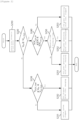
FIG. 2 shows a sequence of an operating method in an energy storage system according to embodiments of the present invention. - The operating method of the energy storage system according to the present invention may be performed by a control apparatus located in the energy storage system. The control apparatus according to embodiments of the present invention may be a power management system (PMS) or an energy management system (EMS), but the scope of the present invention is not limited to these entities.
- The control apparatus receives state information of a plurality of photovoltaic modules, a plurality of battery racks, a DC/DC converter and a power conversion system (S210).
- It is determined whether a DC voltage value (VPV) of the photovoltaic module among the received state information is equal to or greater than a starting DC voltage value (Vinv_start) of the power conversion system (S220). In the instance that the DC voltage value (VPV) of the photovoltaic module is less than the starting DC voltage (Vinv_start) of the power conversion system (No in S220), the DC voltage of the photovoltaic module is compared with a starting DC voltage of the DC/DC converter and the starting DC voltage of the power conversion system (S230).
- In the instance that the DC voltage of the photovoltaic module is greater than or equal to the starting DC voltage (VDCDC_start) of the DC/DC converter and less than the starting DC voltage of the power conversion system (Yes in S230), the power conversion system is stopped and charging for DC/DC converter is performed (S232). When the DC voltage output from the photovoltaic module is less than the starting DC voltage of the DC/DC converter, the entire ESS system is stopped (S231).
- Returning back to step 220, when the DC voltage value (VPV) of the photovoltaic module is greater than or equal to the starting DC voltage (Vinv_start) of the power conversion system (Yes in S220), the power conversion system starts power generating operation (S251, S252, S253). The control apparatus may determine which operation the DC/DC converter should perform while the power conversion system is generating power. Specifically, the control apparatus may compare a SOC value of the battery rack with the upper limit (SOCLim_up) as to SOC of the battery rack and the lower limit (SOCLim_dn) as to SOC of the battery rack (S240). Here, the State of Charge (SOC) represents a current charge rate of the battery rack in percentage [%].
- If the SOC value of the battery rack is between the upper limit and the lower limit, the DC/DC converter is discharged if the operating time is in a discharge time zone (S252). On the other hand, if the operating time is in a charge time zone, the DC/DC converter is charged (S251). If the SOC of the battery rack is not between the upper limit and the lower limit (No in S240), the DC/DC converter stops its operation (S253). Even when the DC/DC converter is stopped, the power conversion system is still generating power.
-
FIG.3 is a conceptual diagram schematically illustrating an operating method of an energy storage system according to embodiments of the present invention. - The horizontal axis in
FIG.3 represents an operation or driving time (t) of the system, and the vertical axis represents power (p). One of the two curves ofFIG. 3 represents an output power according to maximum power point tracking (MPPT) control of the photovoltaic modules, and the other represents generated power from the power conversion system. - Looking from the leftmost side of the time axis in the graph of
FIG. 3 , the first area E is an area in which neither the power conversion system nor the DC/DC converter operates. - Area A, following area E, represents a case in which the DC voltage (VPV) of the photovoltaic module is lower than the starting DC voltage (Vinv_start) of the power conversion system. In this instance, the power conversion system is in a stopped state, and the DC/DC converter charges the battery rack through charge control. Here, the charge amount of the DC/DC converter may be represented as in Equation 1 below.

- In Equation 1, PDCDC represents a charge amount of the DC/DC converter, and PPV_MPPT represents output power according to maximum power point tracking control of the photovoltaic modules.
- Here, the Maximum Power Point Tracking (MPPT) control is a form of control that allows to obtain the maximum power by appropriately adjusting a load according to external situations. A point at which the maximum power is transmitted is referred to as the maximum power point, and the maximum power point may be changed according to external conditions such as solar radiation and temperatures.
- Thereafter, in area B in which the DC voltage of the photovoltaic modules becomes greater than the starting DC voltage (Vinv_start ) of the power conversion system, the power conversion system starts generating power, and the DC/DC converter is charged with a constant value during a charge time period. Here, the amount of power generated by the power conversion system may be represented as in Equation 2 below.

- In Equation 2, Pinv represents an amount of power generated by the power conversion system, PPV_MPPT represents an output power value according to the maximum power point tracking control of the photovoltaic modules, and PDCDC represents a charge amount of the DC/DC converter.
- Thereafter, when the state of charge of the battery rack is located between the upper and lower limits during a discharge time period (area C) of the battery, the power conversion system generates power up to the maximum output point of the photovoltaic module, and the DC/DC converter additionally discharges to maintain the maximum output value of the power conversion system. Here, the amount of power generation of the power conversion system may be indicated as in Equation 3 below. Furthermore, the discharge amount of the DC/DC converter may be represented as Equation 4 below.


- In Equations 3 and 4, Pinv indicates the amount of power generation of the power conversion system, PPV_MPPT indicates an output value according to maximum power point tracking control of the photovoltaic modules, PDCDC indicates a discharge amount of the DC/DC converter, and Pinv_max indicates the maximum output value of the power conversion system.
- In area D, the output of the power conversion system and the output of the photovoltaic modules are the same, and thus, the DC/DC converter stops its operation. Thereafter, the same operations described above may be performed as in the area named same in following sections of area C, area B, area A, and area E, respectively.
-
FIG. 4 is a block diagram of an apparatus for controlling operations of an energy storage system according to embodiments of the present invention. - The apparatus for controlling operation of an energy storage system according to embodiments of the present invention is an operation control apparatus of an energy storage system that is connected with at least one photovoltaic module and a power grid and includes a plurality of battery racks. The apparatus for controlling operation of an energy storage system may include at least one
processor 310, amemory 320 for storing at least one instruction executed by the processor, and atransceiver 330 for communicating with other components in the energy storage system. - The at least one instruction may include an instruction to monitor states of the plurality of battery racks, the DC/DC converter configured to control charging and discharging of the plurality of battery racks, the photovoltaic modules, and the power conversion system configured to receive an output of the DC link as an input and convert the output of the DC link into AC power; an instruction to compare a DC voltage of the photovoltaic modules and a DC voltage of the power conversion system; and an instruction to control operations of the power conversion system and the DC/DC converter according to the result of comparison.
- In the embodiment, the instruction to control operations of the power conversion system and the DC/DC converter may include, upon the DC voltage of the photovoltaic modules being less than the starting DC voltage of the power conversion system, an instruction to control the DC/DC converter to perform charging for the battery rack.
- In addition, the instruction to control operations of the power conversion system and the DC/DC converter may include, upon the DC voltage of the photovoltaic modules being higher than or equal to the DC voltage of the power conversion system, an instruction to control the power conversion system to start generating power; and an instruction to control the DC/DC converter to perform charging and discharging according to an operating time period.
- Somehow, the instruction to control operations of the power conversion system and the DC/DC converter may include: upon a state of charge of the battery racks being within a certain range during a discharge time period, an instruction to control the power conversion system to perform power generation using maximum power point tracking control of the photovoltaic modules; and an instruction to control the DC/DC converter to discharge so as to maintain the output of the power conversion system as the maximum output value.
- In addition, the instruction to control operations of the power conversion system and the DC/DC converter may include: upon a state of charge of the battery racks being within a certain range during a charge time period, an instruction to control the power conversion system to generate power based on an output value according to maximum power point tracking control of the photovoltaic modules and a charge amount of the DC/DC converter; and an instruction to control the DC/DC converter to perform charging with a constant value.
- The
apparatus 300 for controlling operations of the energy storage system may further include aninput interface 340, anoutput interface 350, astorage device 360, and the like. Components included in theapparatus 300 may be connected by abus 370 to communicate with each other. - The
processor 310 may execute a program instruction stored in at least one of thememory 320 and thestorage device 360. Here, the processor may include a central processing unit (CPU), a graphics processing unit (GPU), or a dedicated processor on which a method according to embodiments of the present invention are performed. The memory (or storage device) may be configured as at least one of a volatile storage medium and a non-volatile storage medium. For example, the memory may be configured as at least one of a read only memory (ROM) and a random access memory (RAM). - The operations of the method according to the embodiments of the present invention may be implemented as a computer-readable program or code on a computer-readable recording medium. The computer-readable recording medium includes all types of recording devices in which data readable by a computer system is stored. In addition, the computer-readable recording medium may be distributed in a network-connected computer system to store and execute computer-readable programs or codes in a distributed manner.
- Although some aspects of the invention have been described in the context of the apparatus, it may also represent a description according to a corresponding method, wherein a block or apparatus corresponds to a method step or feature of a method step. Similarly, aspects described in the context of a method may also represent a feature of a corresponding block or item or a corresponding apparatus. Some or all of the method steps may be performed by (or using) a hardware device, such as, for example, a microprocessor, a programmable computer, or an electronic circuit. In some embodiments, one or more of the most important method steps may be performed by such an apparatus.
- In the forgoing, the present invention has been described with reference to the exemplary embodiment of the present invention, but those skilled in the art may appreciate that the present invention may be variously corrected and changed within the range without departing from the spirit and the area of the present invention described in the appending claims.
Claims (15)
- An energy storage system connected with at least one photovoltaic module and a power grid and including a plurality of battery racks, the system comprising:a DC/DC converter configured to control charging and discharging of the plurality of battery racks;a DC (direct current) connector configured to connect the photovoltaic module and the DC/DC converter;a power conversion system configured to receive an output of the DC connector as input and convert the output of the DC connector into AC (alternating current) power; anda controller configured to monitor states of the plurality of battery racks, the DC/DC converter, the photovoltaic module, and the power conversion system, compare a DC voltage of the photovoltaic module and a DC voltage of the power conversion system, and control operations of the power conversion system and the DC/DC converter according to a result of comparison.
- The energy storage system of claim 1, wherein the controller is configured, upon the DC voltage of the photovoltaic module being less than a starting DC voltage of the power conversion system, to control the DC/DC converter to perform charging for the plurality of battery racks.
- The energy storage system of claim 1, wherein the controller is configured, upon the DC voltage of the photovoltaic module being higher than or equal to the DC voltage of the power conversion system, to control the power conversion system to start generating power and to control the DC/DC converter to perform charging and discharging according to an operating time period.
- The energy storage system of claim 3, wherein the controller is configured, upon a state of charge of the battery racks being within a certain range during a discharge time period, to control the power conversion system to perform power generation using maximum power point tracking control of the photovoltaic module and to control the DC/DC converter to discharge so as to maintain the output of the power conversion system as the maximum output value.
- The energy storage system of claim 3, wherein the controller is configured, upon a state of charge of the battery racks being within a certain range during a charge time period, to control the power conversion system to generate power based on an output value according to maximum power point tracking control of the photovoltaic module and a charge amount of the DC/DC converter and to control the DC/DC converter to perform charging with a constant value.
- An operating method of an energy storage system connected with at least one photovoltaic module and a power grid and including a plurality of battery racks, the method comprising:monitoring states of the plurality of battery racks, a DC/DC converter configured to control charging and discharging of the plurality of battery racks, the photovoltaic module, and a power conversion system configured to receive an output of a DC (direct current) connector as an input and convert the output of the DC connector into AC (alternating current) power;comparing a DC voltage of the photovoltaic module and a DC voltage of the power conversion system; andcontrolling operations of the power conversion system and the DC/DC converter according to a result of comparison.
- The operating method of claim 6, wherein the controlling operations of the power conversion system and the DC/DC converter includes, upon the DC voltage of the photovoltaic module being less than a starting DC voltage of the power conversion system, controlling the DC/DC converter to perform charging for the plurality of battery racks.
- The operating method of claim 6, wherein the controlling operations of the power conversion system and the DC/DC converter includes, upon the DC voltage of the photovoltaic module being higher than or equal to the DC voltage of the power conversion system, controlling the power conversion system to start generating power and controlling the DC/DC converter to perform charging and discharging according to an operating time period.
- The operating method of claim 8, wherein the controlling operations of the power conversion system and the DC/DC converter includes, upon a state of charge of the battery racks being within a certain range during a discharge time period, controlling the power conversion system to perform power generation using maximum power point tracking control of the photovoltaic module and controlling the DC/DC converter to discharge so as to maintain the output of the power conversion system as the maximum output value.
- The operating method of claim 8, wherein the controlling operations of the power conversion system and the DC/DC converter includes, upon a state of charge of the battery racks being within a certain range during a charge time period, controlling the power conversion system to generate power based on an output value according to maximum power point tracking control of the photovoltaic module and a charge amount of the DC/DC converter and controlling the DC/DC converter to perform charging with a constant value.
- An apparatus for controlling operations of an energy storage system connected with at least one photovoltaic module and a power grid and including a plurality of battery racks, the apparatus comprising:at least one processor; anda memory configured to store at least one instruction executed by the at least one processor,wherein the at least one instruction includes:an instruction to monitor states of the plurality of battery racks, a DC/DC converter configured to control charging and discharging of the plurality of battery racks, the photovoltaic module, and a power conversion system configured to receive an output of a DC (direct current) connector as an input and convert the output of the DC connector into AC (alternating current) power;an instruction to compare a DC voltage of the photovoltaic module and a DC voltage of the power conversion system; andan instruction to control operations of the power conversion system and the DC/DC converter according to a result of comparison.
- The apparatus of claim 11, wherein the instruction to control operations of the power conversion system and the DC/DC converter includes:upon the DC voltage of the photovoltaic module being less than the starting DC voltage of the power conversion system,an instruction to control the DC/DC converter to perform charging for the battery rack.
- The apparatus of claim 11, wherein the instruction to control operations of the power conversion system and the DC/DC converter includes:upon the DC voltage of the photovoltaic module being higher than or equal to the DC voltage of the power conversion system,an instruction to control the power conversion system to start generating power; andan instruction to control the DC/DC converter to perform charging and discharging according to an operating time period.
- The apparatus of claim 13, wherein the instruction to control operations of the power conversion system and the DC/DC converter includes:upon a state of charge of the battery racks being within a certain range during a discharge time period,an instruction to control the power conversion system to perform power generation using maximum power point tracking control of the photovoltaic module; andan instruction to control the DC/DC converter to discharge so as to maintain the output of the power conversion system as the maximum output value.
- The apparatus of claim 13, wherein the instruction to control operations of the power conversion system and the DC/DC converter includes:upon a state of charge of the battery racks being within a certain range during a charge time period,an instruction to control the power conversion system to generate power based on an output value according to maximum power point tracking control of the photovoltaic module and a charge amount of the DC/DC converter; andan instruction to control the DC/DC converter to perform charging with a constant value.
Applications Claiming Priority (2)
| Application Number | Priority Date | Filing Date | Title |
|---|---|---|---|
| KR1020210140844A KR102784295B1 (en) | 2021-10-21 | 2021-10-21 | Energy storage system including battery racks and photovolatic modules and operating method thereof |
| PCT/KR2022/012470 WO2023068519A1 (en) | 2021-10-21 | 2022-08-22 | Energy storage system comprising battery rack and solar module, and method for operating energy storage system |
Publications (2)
| Publication Number | Publication Date |
|---|---|
| EP4293853A1 true EP4293853A1 (en) | 2023-12-20 |
| EP4293853A4 EP4293853A4 (en) | 2024-09-25 |
Family
ID=86059363
Family Applications (1)
| Application Number | Title | Priority Date | Filing Date |
|---|---|---|---|
| EP22883746.4A Pending EP4293853A4 (en) | 2021-10-21 | 2022-08-22 | ENERGY STORAGE SYSTEM WITH BATTERY RACK AND SOLAR MODULE AND METHOD FOR OPERATING AN ENERGY STORAGE SYSTEM |
Country Status (6)
| Country | Link |
|---|---|
| US (1) | US20240154454A1 (en) |
| EP (1) | EP4293853A4 (en) |
| JP (1) | JP7651715B2 (en) |
| KR (1) | KR102784295B1 (en) |
| CN (1) | CN116918204A (en) |
| WO (1) | WO2023068519A1 (en) |
Cited By (1)
| Publication number | Priority date | Publication date | Assignee | Title |
|---|---|---|---|---|
| EP4583348A1 (en) * | 2024-01-04 | 2025-07-09 | Wanbang Digital Energy Co., Ltd. | Control method and control device of photovoltaic system |
Families Citing this family (5)
| Publication number | Priority date | Publication date | Assignee | Title |
|---|---|---|---|---|
| CN116806316A (en) * | 2021-09-08 | 2023-09-26 | 株式会社Lg新能源 | Energy storage system including newly installed battery rack and method for controlling the same |
| CN116454980B (en) * | 2023-06-15 | 2023-09-01 | 麦田能源股份有限公司 | Power conversion device and maximum power point tracking control method |
| CN118659439A (en) * | 2024-05-29 | 2024-09-17 | 广东博电通新能源科技有限公司 | A control method and control device for photovoltaic energy storage micro inverter |
| CN118554602A (en) * | 2024-07-29 | 2024-08-27 | 洛阳库里南新能源科技有限公司 | Safety type electric energy storage system for photovoltaic power generation |
| KR20260021392A (en) * | 2024-08-06 | 2026-02-13 | 한화솔루션 주식회사 | Control Device, Photovoltaic System Including The Control Device And Control Method For Photovoltaic System |
Family Cites Families (12)
| Publication number | Priority date | Publication date | Assignee | Title |
|---|---|---|---|---|
| JP4795312B2 (en) * | 2007-07-24 | 2011-10-19 | フジプレアム株式会社 | Power storage type solar power generation system |
| KR101128994B1 (en) * | 2009-04-30 | 2012-03-23 | (주) 이이시스 | Inverter system for charging/discharging grid connected using high density secondary cell and operation method therefor |
| KR101093956B1 (en) * | 2009-12-04 | 2011-12-15 | 삼성에스디아이 주식회사 | Energy storage systems |
| JP6080290B2 (en) * | 2012-09-27 | 2017-02-15 | ホーチキ株式会社 | Solar power system |
| EP3472914B1 (en) * | 2017-05-15 | 2020-06-10 | Dynapower Company Llc | Energy storage system for photovoltaic energy and method of storing photovoltaic energy |
| WO2019053824A1 (en) * | 2017-09-13 | 2019-03-21 | 祐平 山本 | Power adjusting apparatus for solar power plant, power generation system, and power adjusting method for solar power plant |
| KR101871858B1 (en) | 2017-10-12 | 2018-06-27 | 현대건설 주식회사 | System for supplying dc power of bipv and method thereof |
| JP6982820B2 (en) * | 2017-12-27 | 2021-12-17 | パナソニックIpマネジメント株式会社 | Control command system and power conversion system |
| KR102157821B1 (en) | 2018-01-30 | 2020-09-18 | 엘에스일렉트릭(주) | Photovoltaic device |
| KR102019087B1 (en) * | 2018-06-07 | 2019-09-06 | (주)다쓰테크 | Control method of photovoltaic energy storage system |
| KR102180879B1 (en) * | 2020-03-06 | 2020-11-20 | 유림티에스 주식회사 | Photovoltaic power generation system with power converter connected by energy storage device and photovoltaic panel |
| KR102364100B1 (en) | 2020-05-14 | 2022-02-21 | 지의소프트 주식회사 | Table data storing system and method on the electronic document |
-
2021
- 2021-10-21 KR KR1020210140844A patent/KR102784295B1/en active Active
-
2022
- 2022-08-22 EP EP22883746.4A patent/EP4293853A4/en active Pending
- 2022-08-22 CN CN202280018121.1A patent/CN116918204A/en active Pending
- 2022-08-22 WO PCT/KR2022/012470 patent/WO2023068519A1/en not_active Ceased
- 2022-08-22 JP JP2023553098A patent/JP7651715B2/en active Active
- 2022-08-22 US US18/279,361 patent/US20240154454A1/en active Pending
Cited By (1)
| Publication number | Priority date | Publication date | Assignee | Title |
|---|---|---|---|---|
| EP4583348A1 (en) * | 2024-01-04 | 2025-07-09 | Wanbang Digital Energy Co., Ltd. | Control method and control device of photovoltaic system |
Also Published As
| Publication number | Publication date |
|---|---|
| CN116918204A (en) | 2023-10-20 |
| WO2023068519A1 (en) | 2023-04-27 |
| JP7651715B2 (en) | 2025-03-26 |
| US20240154454A1 (en) | 2024-05-09 |
| KR102784295B1 (en) | 2025-03-19 |
| EP4293853A4 (en) | 2024-09-25 |
| KR20230056968A (en) | 2023-04-28 |
| JP2024509135A (en) | 2024-02-29 |
Similar Documents
| Publication | Publication Date | Title |
|---|---|---|
| US20240154454A1 (en) | Energy storage system comprising battery rack and solar module, and method for operating energy storage system | |
| EP4054051B1 (en) | Energy storage system and battery management method | |
| JP5272040B2 (en) | Power storage system and control method thereof | |
| JP5676767B2 (en) | Power conversion system for energy storage system and control method thereof | |
| EP3148037B1 (en) | Energy storage system | |
| KR102479719B1 (en) | System and Method for Controlling Battery | |
| EP2490313B1 (en) | Energy storage system and controlling method thereof | |
| EP4293852B1 (en) | Energy storage system associated with solar system and method for controlling energy storage system | |
| KR101369633B1 (en) | Energy storage system and method of controlling the same | |
| JP2013085459A (en) | Power storage system and control method therefor | |
| KR20110098346A (en) | Electric power storage system and control method | |
| US20240383361A1 (en) | Energy storage system interworking with solar power generation system and electric vehicle charging system and method for operating same | |
| EP4027476B1 (en) | Energy storage system comprising multiple battery packs | |
| JP7258371B2 (en) | power supply system | |
| US20240014658A1 (en) | Direct current/direct current converter and control method thereof | |
| US12549016B2 (en) | Energy storage system for optimal operation of newly installed battery rack and control method therefor | |
| US20240235365A1 (en) | Power conversion device for performing dc-dc conversion, and energy storage system including same | |
| US20260066675A1 (en) | Inverter system and method for operating said inverter system | |
| CN121777756A (en) | Control method and device for battery pack and energy storage device | |
| AU2022342981A1 (en) | Energy storage system comprising new installation battery rack, and method for controlling same | |
| JP2023109365A (en) | power supply system |
Legal Events
| Date | Code | Title | Description |
|---|---|---|---|
| STAA | Information on the status of an ep patent application or granted ep patent |
Free format text: STATUS: THE INTERNATIONAL PUBLICATION HAS BEEN MADE |
|
| PUAI | Public reference made under article 153(3) epc to a published international application that has entered the european phase |
Free format text: ORIGINAL CODE: 0009012 |
|
| STAA | Information on the status of an ep patent application or granted ep patent |
Free format text: STATUS: REQUEST FOR EXAMINATION WAS MADE |
|
| 17P | Request for examination filed |
Effective date: 20230913 |
|
| AK | Designated contracting states |
Kind code of ref document: A1 Designated state(s): AL AT BE BG CH CY CZ DE DK EE ES FI FR GB GR HR HU IE IS IT LI LT LU LV MC MK MT NL NO PL PT RO RS SE SI SK SM TR |
|
| A4 | Supplementary search report drawn up and despatched |
Effective date: 20240826 |
|
| RIC1 | Information provided on ipc code assigned before grant |
Ipc: H02J 3/32 20060101AFI20240820BHEP |
|
| DAV | Request for validation of the european patent (deleted) | ||
| DAX | Request for extension of the european patent (deleted) | ||
| STAA | Information on the status of an ep patent application or granted ep patent |
Free format text: STATUS: EXAMINATION IS IN PROGRESS |
|
| 17Q | First examination report despatched |
Effective date: 20250211 |