EP4293830A1 - Antenna device, detecting device, opening and closing unit control system, and passenger detecting system - Google Patents
Antenna device, detecting device, opening and closing unit control system, and passenger detecting system Download PDFInfo
- Publication number
- EP4293830A1 EP4293830A1 EP21925114.7A EP21925114A EP4293830A1 EP 4293830 A1 EP4293830 A1 EP 4293830A1 EP 21925114 A EP21925114 A EP 21925114A EP 4293830 A1 EP4293830 A1 EP 4293830A1
- Authority
- EP
- European Patent Office
- Prior art keywords
- antenna
- convexly curved
- detection device
- circuit board
- reflector
- Prior art date
- Legal status (The legal status is an assumption and is not a legal conclusion. Google has not performed a legal analysis and makes no representation as to the accuracy of the status listed.)
- Granted
Links
Images






Classifications
-
- G—PHYSICS
- G01—MEASURING; TESTING
- G01S—RADIO DIRECTION-FINDING; RADIO NAVIGATION; DETERMINING DISTANCE OR VELOCITY BY USE OF RADIO WAVES; LOCATING OR PRESENCE-DETECTING BY USE OF THE REFLECTION OR RERADIATION OF RADIO WAVES; ANALOGOUS ARRANGEMENTS USING OTHER WAVES
- G01S13/00—Systems using the reflection or reradiation of radio waves, e.g. radar systems; Analogous systems using reflection or reradiation of waves whose nature or wavelength is irrelevant or unspecified
- G01S13/02—Systems using reflection of radio waves, e.g. primary radar systems; Analogous systems
- G01S13/04—Systems determining presence of a target
-
- G—PHYSICS
- G01—MEASURING; TESTING
- G01S—RADIO DIRECTION-FINDING; RADIO NAVIGATION; DETERMINING DISTANCE OR VELOCITY BY USE OF RADIO WAVES; LOCATING OR PRESENCE-DETECTING BY USE OF THE REFLECTION OR RERADIATION OF RADIO WAVES; ANALOGOUS ARRANGEMENTS USING OTHER WAVES
- G01S7/00—Details of systems according to groups G01S13/00, G01S15/00, G01S17/00
- G01S7/02—Details of systems according to groups G01S13/00, G01S15/00, G01S17/00 of systems according to group G01S13/00
- G01S7/03—Details of HF subsystems specially adapted therefor, e.g. common to transmitter and receiver
-
- E—FIXED CONSTRUCTIONS
- E05—LOCKS; KEYS; WINDOW OR DOOR FITTINGS; SAFES
- E05F—DEVICES FOR MOVING WINGS INTO OPEN OR CLOSED POSITION; CHECKS FOR WINGS; WING FITTINGS NOT OTHERWISE PROVIDED FOR, CONCERNED WITH THE FUNCTIONING OF THE WING
- E05F15/00—Power-operated mechanisms for wings
- E05F15/70—Power-operated mechanisms for wings with automatic actuation
- E05F15/73—Power-operated mechanisms for wings with automatic actuation responsive to movement or presence of persons or objects
-
- G—PHYSICS
- G01—MEASURING; TESTING
- G01S—RADIO DIRECTION-FINDING; RADIO NAVIGATION; DETERMINING DISTANCE OR VELOCITY BY USE OF RADIO WAVES; LOCATING OR PRESENCE-DETECTING BY USE OF THE REFLECTION OR RERADIATION OF RADIO WAVES; ANALOGOUS ARRANGEMENTS USING OTHER WAVES
- G01S13/00—Systems using the reflection or reradiation of radio waves, e.g. radar systems; Analogous systems using reflection or reradiation of waves whose nature or wavelength is irrelevant or unspecified
- G01S13/02—Systems using reflection of radio waves, e.g. primary radar systems; Analogous systems
- G01S13/06—Systems determining position data of a target
- G01S13/42—Simultaneous measurement of distance and other co-ordinates
-
- G—PHYSICS
- G01—MEASURING; TESTING
- G01S—RADIO DIRECTION-FINDING; RADIO NAVIGATION; DETERMINING DISTANCE OR VELOCITY BY USE OF RADIO WAVES; LOCATING OR PRESENCE-DETECTING BY USE OF THE REFLECTION OR RERADIATION OF RADIO WAVES; ANALOGOUS ARRANGEMENTS USING OTHER WAVES
- G01S13/00—Systems using the reflection or reradiation of radio waves, e.g. radar systems; Analogous systems using reflection or reradiation of waves whose nature or wavelength is irrelevant or unspecified
- G01S13/88—Radar or analogous systems specially adapted for specific applications
- G01S13/93—Radar or analogous systems specially adapted for specific applications for anti-collision purposes
- G01S13/931—Radar or analogous systems specially adapted for specific applications for anti-collision purposes of land vehicles
-
- G—PHYSICS
- G01—MEASURING; TESTING
- G01S—RADIO DIRECTION-FINDING; RADIO NAVIGATION; DETERMINING DISTANCE OR VELOCITY BY USE OF RADIO WAVES; LOCATING OR PRESENCE-DETECTING BY USE OF THE REFLECTION OR RERADIATION OF RADIO WAVES; ANALOGOUS ARRANGEMENTS USING OTHER WAVES
- G01S7/00—Details of systems according to groups G01S13/00, G01S15/00, G01S17/00
- G01S7/02—Details of systems according to groups G01S13/00, G01S15/00, G01S17/00 of systems according to group G01S13/00
- G01S7/027—Constructional details of housings, e.g. form, type, material or ruggedness
-
- H—ELECTRICITY
- H01—ELECTRIC ELEMENTS
- H01Q—ANTENNAS, i.e. RADIO AERIALS
- H01Q1/00—Details of, or arrangements associated with, antennas
- H01Q1/36—Structural form of radiating elements, e.g. cone, spiral, umbrella; Particular materials used therewith
- H01Q1/38—Structural form of radiating elements, e.g. cone, spiral, umbrella; Particular materials used therewith formed by a conductive layer on an insulating support
-
- H—ELECTRICITY
- H01—ELECTRIC ELEMENTS
- H01Q—ANTENNAS, i.e. RADIO AERIALS
- H01Q19/00—Combinations of primary active antenna elements and units with secondary devices, e.g. with quasi-optical devices, for giving the antenna a desired directional characteristic
- H01Q19/10—Combinations of primary active antenna elements and units with secondary devices, e.g. with quasi-optical devices, for giving the antenna a desired directional characteristic using reflecting surfaces
- H01Q19/106—Combinations of primary active antenna elements and units with secondary devices, e.g. with quasi-optical devices, for giving the antenna a desired directional characteristic using reflecting surfaces using two or more intersecting plane surfaces, e.g. corner reflector antennas
-
- H—ELECTRICITY
- H01—ELECTRIC ELEMENTS
- H01Q—ANTENNAS, i.e. RADIO AERIALS
- H01Q19/00—Combinations of primary active antenna elements and units with secondary devices, e.g. with quasi-optical devices, for giving the antenna a desired directional characteristic
- H01Q19/10—Combinations of primary active antenna elements and units with secondary devices, e.g. with quasi-optical devices, for giving the antenna a desired directional characteristic using reflecting surfaces
- H01Q19/12—Combinations of primary active antenna elements and units with secondary devices, e.g. with quasi-optical devices, for giving the antenna a desired directional characteristic using reflecting surfaces wherein the surfaces are concave
- H01Q19/13—Combinations of primary active antenna elements and units with secondary devices, e.g. with quasi-optical devices, for giving the antenna a desired directional characteristic using reflecting surfaces wherein the surfaces are concave the primary radiating source being a single radiating element, e.g. a dipole, a slot, a waveguide termination
-
- E—FIXED CONSTRUCTIONS
- E05—LOCKS; KEYS; WINDOW OR DOOR FITTINGS; SAFES
- E05F—DEVICES FOR MOVING WINGS INTO OPEN OR CLOSED POSITION; CHECKS FOR WINGS; WING FITTINGS NOT OTHERWISE PROVIDED FOR, CONCERNED WITH THE FUNCTIONING OF THE WING
- E05F15/00—Power-operated mechanisms for wings
- E05F15/70—Power-operated mechanisms for wings with automatic actuation
- E05F15/73—Power-operated mechanisms for wings with automatic actuation responsive to movement or presence of persons or objects
- E05F2015/763—Power-operated mechanisms for wings with automatic actuation responsive to movement or presence of persons or objects using acoustical sensors
-
- E—FIXED CONSTRUCTIONS
- E05—LOCKS; KEYS; WINDOW OR DOOR FITTINGS; SAFES
- E05Y—INDEXING SCHEME ASSOCIATED WITH SUBCLASSES E05D AND E05F, RELATING TO CONSTRUCTION ELEMENTS, ELECTRIC CONTROL, POWER SUPPLY, POWER SIGNAL OR TRANSMISSION, USER INTERFACES, MOUNTING OR COUPLING, DETAILS, ACCESSORIES, AUXILIARY OPERATIONS NOT OTHERWISE PROVIDED FOR, APPLICATION THEREOF
- E05Y2900/00—Application of doors, windows, wings or fittings thereof
- E05Y2900/50—Application of doors, windows, wings or fittings thereof for vehicles
- E05Y2900/53—Type of wing
- E05Y2900/531—Doors
-
- E—FIXED CONSTRUCTIONS
- E05—LOCKS; KEYS; WINDOW OR DOOR FITTINGS; SAFES
- E05Y—INDEXING SCHEME ASSOCIATED WITH SUBCLASSES E05D AND E05F, RELATING TO CONSTRUCTION ELEMENTS, ELECTRIC CONTROL, POWER SUPPLY, POWER SIGNAL OR TRANSMISSION, USER INTERFACES, MOUNTING OR COUPLING, DETAILS, ACCESSORIES, AUXILIARY OPERATIONS NOT OTHERWISE PROVIDED FOR, APPLICATION THEREOF
- E05Y2900/00—Application of doors, windows, wings or fittings thereof
- E05Y2900/50—Application of doors, windows, wings or fittings thereof for vehicles
- E05Y2900/53—Type of wing
- E05Y2900/546—Tailboards, tailgates or sideboards opening upwards
-
- E—FIXED CONSTRUCTIONS
- E05—LOCKS; KEYS; WINDOW OR DOOR FITTINGS; SAFES
- E05Y—INDEXING SCHEME ASSOCIATED WITH SUBCLASSES E05D AND E05F, RELATING TO CONSTRUCTION ELEMENTS, ELECTRIC CONTROL, POWER SUPPLY, POWER SIGNAL OR TRANSMISSION, USER INTERFACES, MOUNTING OR COUPLING, DETAILS, ACCESSORIES, AUXILIARY OPERATIONS NOT OTHERWISE PROVIDED FOR, APPLICATION THEREOF
- E05Y2900/00—Application of doors, windows, wings or fittings thereof
- E05Y2900/50—Application of doors, windows, wings or fittings thereof for vehicles
- E05Y2900/53—Type of wing
- E05Y2900/548—Trunk lids
-
- H—ELECTRICITY
- H01—ELECTRIC ELEMENTS
- H01Q—ANTENNAS, i.e. RADIO AERIALS
- H01Q1/00—Details of, or arrangements associated with, antennas
- H01Q1/12—Supports; Mounting means
- H01Q1/22—Supports; Mounting means by structural association with other equipment or articles
- H01Q1/2283—Supports; Mounting means by structural association with other equipment or articles mounted in or on the surface of a semiconductor substrate as a chip-type antenna or integrated with other components into an IC package
-
- H—ELECTRICITY
- H01—ELECTRIC ELEMENTS
- H01Q—ANTENNAS, i.e. RADIO AERIALS
- H01Q1/00—Details of, or arrangements associated with, antennas
- H01Q1/27—Adaptation for use in or on movable bodies
- H01Q1/32—Adaptation for use in or on road or rail vehicles
- H01Q1/3208—Adaptation for use in or on road or rail vehicles characterised by the application wherein the antenna is used
- H01Q1/3233—Adaptation for use in or on road or rail vehicles characterised by the application wherein the antenna is used particular used as part of a sensor or in a security system, e.g. for automotive radar, navigation systems
Definitions
- the present invention relates to an antenna device, a detection device, an opening/closing unit control system, and an occupant detection system.
- a vehicle-mounted radar device that has a millimeter-wave radar and a reflecting mirror that reflects transmission and reception waves of the millimeter-wave radar.
- the reflecting mirror is a half-truncated cone body the radius of which is longer than the height.
- a side surface of the half-truncated cone body is a reflecting surface.
- the reflecting surface is a concavely curved surface formed by curving the generating line of the truncated cone toward the bottom face (see PTL 1, for example).
- a reflecting surface with the generating line of a half-truncated cone body curved toward the bottom face as with the reflecting surface of the reflecting mirror of the conventional vehicle-mounted radar device, has a complex shape and is not easy to design.
- an object is to provide an antenna device having a reflector that has a simple structure and is easy to design, a detection device, an opening/closing control system, and an occupant detection system.
- An antenna device in an embodiment of the present invention includes: a circuit board; an antenna placed on a surface of the circuit board; and a reflector that is erected on the surface of the circuit board and extends along the surface.
- the reflector has: a curved portion that has a convexly curved surface, which is curved at a certain curvature and protrudes toward the same side as the antenna, the convexly curved surface reflecting radio waves emitted by the antenna; and a first plane portion and a second plane portion that respectively have a first reflecting surface and a second reflecting surface that extend from both side portions of the convexly curved surface along the surface of the circuit board, form a V shape together with the convexly curved surface in plan view, and reflect radio waves emitted by the antenna.
- the convexly curved surface has a shape equivalent to a portion on the outer circumferential surface of a cylinder, the portion being included in a certain azimuth angle from a cylindrical axis.
- the convexly curved surface is inclined toward the same side as the antenna with respect to the circuit board.
- an antenna device having a reflector that has a simple structure and is easy to design, a detection device, an opening/closing control system, and an occupant detection system.
- a direction (X direction) parallel to the X axis, a direction (Y direction) parallel to the Y axis, and a direction (Z direction) parallel to the Z axis are mutually orthogonal.
- the -Z-direction side may be referred to as the lower side or bottom, and the +Z-direction side may be referred to as the upper side or top, for convenience of explanation.
- “in plan view” will refer to an XY plane being viewed.
- Fig. 1 is a drawing indicating a detection device 100 in an embodiment.
- an ECU (Electronic Control Unit) 300 is also indicated.
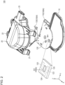
- Fig. 2 is an exploded view of the detection device 100.
- the detection device 100 includes a lower case 10, an upper case 20, a circuit board 110, a transmission and reception device 120, and a reflector 130.
- the transmission and reception device 120 has an antenna 121, a transmission circuit 122, a reception circuit 123, and a control unit 124.
- the detection device 100 includes at least the circuit board 110, transmission and reception device 120, and reflector 130.
- An antenna device 100A in the embodiment includes at least the circuit board 110, antenna 121, and reflector 130.
- the reference characters 100A are indicated in parentheses for the circuit board 110, antenna 121, and reflector 130.
- the lower case 10 and upper case 20 which are an example of a cabinet, become a case having a sealed internal space by being aligned and engaged.
- the circuit board 110, transmission and reception device 120, and reflector 130 are stored in the internal space in the case formed with the lower case 10 and upper case 20, the circuit board 110, transmission and reception device 120, and reflector 130 are stored.
- the detection device 100, the circuit board 110, transmission and reception device 120, and reflector 130 are packaged by being stored in the lower case 10 and upper case 20.
- the upper case 20 has engagement portions 21, screw holes 22, and a connector 23.
- the engagement portions 21 and screw holes 22 are an example of an attachment portion that can attach the case formed with the lower case 10 and upper case 20 at a lower portion of a door of a vehicle, inside the bumper, or in the interior of the room of the vehicle.
- the connector 23 has terminals to be connected to the transmission and reception device 120 through the circuit board 110.
- the connector 23 is connected to the ECU 300 in the vehicle through, for example, LIN (Local Interconnect Network) or CAN (Controller Area Network) mounted in the vehicle.
- the detection device 100 is connected to the ECU 300 through the connector 23.
- the detection device 100 like this can be used as an operation detection device for an electric opener for an opening/closing portion of the trunk lid, the rear gate, a slide door, or the like of a vehicle.
- the detection device 100 detects the presence or motion of the toes of the user of the vehicle below the rear bumper.
- the user who inserts the toes below the rear bumper is an example of a manipulator present around a vehicle.
- the electric opener is a device that performs unlocking of a lock and driving of an actuator that opens and closes an opening/closing portion of a trunk lid, a rear gate, a slide door, or the like.
- the ECU 300 is a control unit that controls the opening and closing of an opening/closing portion of a vehicle according to a detection result of the detection device 100
- a system including the detection device 100 and ECU 300 is an opening/closing control system.
- the ECU 300 is an occupant detection unit that detects the presence or absence of an occupant in the room of a vehicle according to a detection result of the detection device 100
- a system including the detection device 100 and ECU 300 is an occupant detection system.
- the detection device 100 When the detection device 100 is used as an operation detection device for an electric opener for the trunk lid or rear gate of a vehicle, the detection device 100 is provided, as an example, inside the rear bumper of the vehicle at the center in the width direction of the vehicle.
- the +X direction is the vertically downward direction
- the -X direction is the vertically upward direction
- the +Y direction is on the right side in the travel direction of the vehicle
- the -Y direction is on the left side in the travel direction of the vehicle
- the +Z direction is the backward of the vehicle
- the +Z direction is the forward of the vehicle.
- the detection device 100 emits radio waves in the +X direction, receives reflected waves, and detects, in the +X direction, the presence of a detection target or the behavior of the detection target.
- the detection device 100 is provided inside the rear bumper of a vehicle and detects the presence or motion of the toes of the user who is going to operate the electric opener of the trunk lid or rear gate. That is, in the description below, the detection target of the detection device 100 is the toes of the user, as an example.
- the detection device 100 detects, in the +X direction, the presence of the detection target or the behavior of the detection target by emitting radio waves in the +X direction and receiving reflected waves.
- a timing to receive a reflected wave differs between a case in which the toes of the user, which are the detection target, are not present below the detection device 100 and a case in which the toes are present. Therefore, the detection device 100 detects at least one of the presence of the toes and a behavior in which the toes have been inserted below the detection device 100.
- Fig. 3 to Fig. 6 are drawings indicating the detection device 100 and antenna device 100A.
- the circuit board 110, transmission and reception device 120, and reflector 130 are indicated.
- the circuit board 110 has a shape matching the shapes of the lower case 10 and upper case 20 in plan view, as indicated in Fig. 2 to Fig. 4 .
- the circuit board 110 is, for example, is a wiring board complying with the FR4 (Flame Retardant type 4) standard or the like.
- the transmission and reception device 120 and reflector 130 are mounted on the upper surface 111 of the circuit board 110.
- the control unit 124 (see Fig. 2 ) of the transmission and reception device 120 is connected to the terminals of the connector 23 (see Fig. 1 and Fig. 2 ) through wires on the circuit board 110.
- the circuit board 110 is fixed in the interior of the upper case 20 with screws or the like, as an example.
- the transmission and reception device 120 has the antenna 121, transmission circuit 122, reception circuit 123, and control unit 124 as indicated in Fig. 2 by being enlarged, and is mounted on the upper surface 111 of the circuit board 110 as indicated in Fig. 2 to Fig. 6 . Portions of the transmission circuit 122, reception circuit 123, and control unit 124 in the transmission and reception device 120 are implemented as a so-called IC (Integrated Circuit) chip.
- IC Integrated Circuit
- the antenna 121 is provided on the upper surface of the IC chip and is connected to the transmission circuit 122 and reception circuit 123.
- the antenna 121 is a patch antenna as an example, and is an antenna that doubles as a transmission antenna for transmitting radio waves and a reception antenna for receiving radio waves.
- the antenna 121 can transmit and receive millimeter-waves at 60.5 GHz, as an example.
- the transmission circuit 122 and reception circuit 123 are integrally formed in an analog integrated circuit included in the IC chip. Also, the transmission circuit 122 and reception circuit 123 are connected to the control unit 124, and their operations are controlled by the control unit 124.
- the transmission circuit 122 outputs a transmission signal to the antenna 121 in response to a transmission command output from the control unit 124.
- the reception circuit 123 receives a reflected wave, which is a transmission signal reflected at the detection target.
- the control unit 124 represents functions implemented by a computer included in the IC chip.
- the control unit 124 has functions used as a detection unit that detects at least one of the presence and behavior of the detection target according to a signal received by the reception circuit 123.
- the reflector 130 is erected on the upper surface 111 of the circuit board 110 as indicated in Fig. 3 to Fig. 6 .
- Erection on the upper surface 111 refers to provision in an erected state on the upper surface 111 or provision in a standing state on the upper surface 111.
- the reflector 130 is provided so as to be inclined with respect to the upper surface 111. Details of this will be described later.
- the reflector 130 has a curved portion 131, flat plate portions 132 and 133, fixing portions 134, and engaging portions 135.
- the flat plate portion 132 is an example of a first plane portion
- the flat plate portion 133 is an example of a second plane portion.
- the curved portion 131 and flat plate portions 132 and 133 extend along the upper surface 111 of the circuit board 110.
- the reflector 130 reflects radio waves emitted by the antenna 121 toward the +X-direction side. Also, the reflector 130 reflects radio waves reflected on the detection target toward the antenna 121.
- the reflector 130 Since the reflector 130 is provided in the interior of the rear bumper of the vehicle at the center of the width direction of the vehicle, the reflector 130 demanded to enable the reflected wave to reach a farther distance in a lower left direction and lower right direction of the rear bumper of the vehicle. This is to enable the toes of the user to be detected in a wider range in the left-right direction.
- the reflector 130 is structured so that it can reflect radio waves farther in a lower left direction, which is on the -Y-direction side in the +X direction and in a lower right direction, which is on the + Y-direction side in the +X direction.
- the reflector 130 of the antenna device 100A and detection device 100 in this embodiment has a relatively simple structure.
- the curved portion 131 has a convexly curved surface 131S, which is curved at a certain curvature and protrudes toward the same side as the transmission and reception device 120 having the antenna 121 (see Fig. 2 ).
- the convexly curved surface 131S is the reflecting surface of the curved portion 131.
- the curved portion 131 has a shape in which a flat plate is curved.
- the convexly curved surface 131S has a shape equivalent to a portion on the outer circumferential surface of a cylinder, the portion being included in a certain azimuth angle from a cylindrical axis.
- the curved portion 131 is inclined toward the same side as the transmission and reception device 120 having the antenna 121 (see Fig. 2 ), with respect to the upper surface 111 of the circuit board 110.
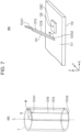
- Fig. 7 is a drawing indicating the curved portion 131.
- Fig. 7 only the curved portion 131 in the reflector 130 is extracted and indicated; and a cylinder 1 including the curved portion 131, the cylinder 1 being vertical, is indicated.
- Fig. 8 is a drawing indicating a cross section along A-A in Fig. 4 .
- Fig. 9 is a drawing indicating a cross section along B-B in Fig. 4 .
- the curved portion 131 is a portion on the cylinder 1 having a radius vector R and a cylindrical axis C, the portion being included within an azimuth angle ⁇ with respect to the cylindrical axis C.
- the azimuth angle ⁇ is an example of a certain azimuth angle.
- the curved portion 131 has a vertex 131A1 of an arc, the vertex 131A1 being at the upper end of the convexly curved surface 131S, a vertex 131A2 of the arc, the vertex 131A2 being at the lower end of the convexly curved surface 131S, and a straight line 131B linking the vertex 131A1 and vertex 131A2 together.
- the straight line 131B is positioned on the convexly curved surface 131S and is parallel to the cylindrical axis C.
- the straight line 131B is a straight line equivalent to the generating line of the cylinder 1.
- the curved portion 131 is placed on the upper surface 111 so that the straight line 131B linking the vertex 131A1 and vertex 131A2 together is positioned on a plane parallel to an XZ plane and passing through the center 120C of the upper surface of the transmission and reception device 120 and that the straight line 131B is inclined toward the same side as the transmission and reception device 120. Since the straight line 131B is inclined toward the same side as the transmission and reception device 120, the convexly curved surface 131S is inclined toward the same side as the transmission and reception device 120.
- the center 120C is equivalent to the center of the surface of the antenna 121 (see Fig. 2 ).
- the curved portion 131 is inclined so that the angle formed by the upper surface 111 and the straight line 131B linking the vertex 131A1 and vertex 131A2 together becomes an angle ⁇ on a plane parallel to an XZ plane and passing through the center 120C of the transmission and reception device 120.
- the convexly curved surface 131S has a shape in which the convexly curved surface 131S is curved in the circumferential direction as with the outer circumferential surface of the cylinder 1, but is not curved in a direction parallel to the cylindrical axis C and straight line 131B.
- the angle ⁇ is 52 degrees as an example, as indicated in Fig. 8 .
- the curved portion 131 like this is relatively easy to design.
- the curved portion 131 can be manufactured by bending a flat plate to a radius R of curvature along the cylindrical axis C, which is vertical.
- the angle ⁇ is not limited to 52 degrees.
- the angle ⁇ is an acute angle (an angle greater than 0 degree and smaller than 90 degrees).
- the curved portion 131 overlaps the transmission and reception device 120 in plan view, as an example.
- an aspect is indicated in which the curved portion 131 overlaps the whole of the transmission and reception device 120.
- the curved portion 131 preferably overlaps at least part of the transmission and reception device 120 in plan view. This is because radio waves emitted from the antenna 121 (see Fig. 2 ) of the transmission and reception device 120 can be efficiently reflected.
- the antenna 121 emits radio waves toward the same side as the curved portion 131 with respect to the vertically upward direction
- the curved portion 131 may not overlap the transmission and reception device 120 in plan view.
- Both of the flat plate portions 132 and 133 are a portion in a flat plate shape (plate-like), and respectively have surfaces 132S and 133S on the +X-direction side, as indicated in Fig. 3 , Fig. 5 , and Fig. 6 .
- the surfaces 132S and 133S are the reflecting surfaces of the flat plate portions 132 and 133.
- the surface 132S is an example of a first reflecting surface
- the surface 133S is an example of a second reflecting surface.
- the surfaces 132S and 133S extend from both side portions of the convexly curved surface 131S in the circumferential direction along the upper surface 111 of the circuit board 110, and form a V shape together with the convexly curved surface 131S in plan view as indicated by the broken lines in Fig. 4 .
- the angle (interior angle) ⁇ of the V shape formed by the surfaces 132S and 133S is 120 degrees, as an example.
- the angle ⁇ is preferably greater than or equal to 90 degrees.
- the flat plate portion 132 is provided continuously from the side portion of the curved portion 131 on the -Y-direction side in the circumferential direction, and the flat plate portion 133 is provided continuously from the side portion of the curved portion 131 on the +Y-direction side in the circumferential direction. Therefore, the surface 132S is a surface continuous from the end of the convexly curved surface 1315 on the -Y-direction side, and the surface 133S is a surface continuous from the end of the convexly curved surface 131S on the +Y -direction side.
- the angle formed by the surface 132S and upper surface 111 is ⁇ , so the angle is equal to the angle ⁇ formed by the upper surface 111 and the straight line 131B of the curved portion 131.
- the angle ⁇ is 52 degrees, as an example.
- the flat plate portion 132 and flat plate portion 133 have a symmetric shape (plane symmetry), in which they are mutual mirror images, with respect to a plane that includes the straight line 131B of the curved portion 131 and is parallel to an XZ plane, when the cross section, of the flat plate portion 133, taken along a plane parallel to an XZ plane is viewed, the angle formed by the surface 133S and upper surface 111 is ⁇ , so the angle is equal to the angle ⁇ formed by the upper surface 111 and the straight line 131B of the curved portion 131.
- the two fixing portions 134 are a portion extending from an end of the flat plate portion 132 on the -Y-direction side and a portion extending from an end of the flat plate portion 133 on the +Y-direction side.
- the fixing portions 134 extend in the -X direction.
- the fixing portions 134 are provided to stably fix the reflector 130 on the upper surface of the circuit board 110, and have convex portions 134A (see Fig. 6 ) protruding downward.
- the convex portions 134A are inserted into through-holes passing through the circuit board 110 in the thickness direction (Z direction), and are fixed to the circuit board 110 with an adhesive or the like.
- the two engaging portions 135 are portions extending from the lower ends of the flat plate portion 132 and flat plate portion 133.
- the engaging portion 135 is inserted into a through-hole passing through the circuit board 110 in the thickness direction (Z direction), and is fixed to the circuit board 110 with an adhesive or the like.
- a direction in which the +X direction is viewed from the vertexes 131A 1 and 131A2 in plan view is the direction of the front of the reflector 130 and is the direction of the fronts of the antenna device 100A and detection device 100.
- the reflector 130 having the curved portion 131, flat plate portions 132 and 133, fixing portions 134, and engaging portions 135 as described above can be manufactured by, for example, bending a metal plate obtained by performing punching processing to stamp a sheet metal to the radius R of curvature along the cylindrical axis C, which is vertical.
- the metal plate may be made of, for example, aluminum.
- Fig. 10 is a drawing indicating an evaluation coordinate system for the detection device 100. Since the detection device 100 includes the antenna device 100A, evaluation results for the detection device 100 will be described below. Descriptions will be given below, assuming that, as indicated in Fig. 10 , the XYZ coordinate system is the same as the XYZ coordinate system indicated in Fig. 1 to Fig. 9 and that the origin matches the center 120C (see Fig. 7(B) ) on the upper surface of the transmission and reception device 120.
- the evaluation coordinate system is a polar coordinate system.
- the azimuth angle indicates an angle in a direction indicated by an arrow with the -Y direction taken as a reference (0 degree). Therefore, the azimuth angle in the +X direction is 90 degrees and the azimuth angle in the +Y direction is 180 degrees.
- the azimuth angle in the -X direction is 270 degrees and is also -90 degrees.
- the elevation angle indicates an angle in a direction indicated by an arrow with the +X direction taken as a reference (0 degree). Therefore, the elevation angle in the +Z direction is 90 degrees and the azimuth angle in the -Z direction is - 90.
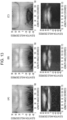
- Fig. 11 is a drawing indicating simulation results for emission strength of the detection device 100.
- the horizontal axis indicates the azimuth angle (degrees) and the vertical axis indicates the elevation angle (degrees).
- Fig. 11(A) to Fig. 11(C) it is represented that the brighter, the higher emission strength is, and that the darker, the lower emission strength is.
- a detection device 50 for comparison purposes is indicated below the simulation result of emission strength in Fig. 11(C) .
- the detection device 50 for comparison purposes has a reflector 53 for which a reflecting surface equivalent to the convexly curved surface 131S of the curved portion 131 of the reflector 130 and to the surfaces 132S and 133S of the flat plate portions 132 and 133 is a parabolic surface.
- Fig. 12 is a drawing indicating simulation results for emission strength of the detection device 100.
- the characteristics of emission strength (dB) with respect to the azimuth angle in a plane with an elevation angle of 10 degrees are indicated at the upper stage and the characteristics of emission strength with respect to the elevation angle in an XZ plane are indicated at the lower stage.
- An XZ plane is a plane with an azimuth angle of 90 degrees.
- Fig. 11(A) and Fig. 12(A) indicate emission strength for a simulation model for which the radius vector R of the curved portion 131 is 7.5 mm and the angle ⁇ of the letter V of the reflector 130 is 120 degrees.
- Fig. 11(B) and Fig. 12(B) indicate emission strength for a simulation model for which the radius vector R of the curved portion 131 is 7.5 mm and the angle ⁇ of the letter V of the reflector 130 is 150 degrees.
- Fig. 11(C) and Fig. 12(C) indicate emission strength in simulation results for the detection device 50 for comparison purposes.
- the range of the azimuth angle from 40 degrees to 50 degrees and the range of the azimuth angle from 130 degrees to 140 degrees are a wide-angle range in angles at which radio waves that are emitted from the antenna 121 and are reflected by the reflector 130 propagate in an XY plane, the wide-angle range being a range of wide angles with respect to the direction at an azimuth angle of 90 degrees.
- the direction at an azimuth angle of 90 degrees is the direction of the front of the reflector 130.
- the wide-angle range is a range in which angles with respect to direction of the front of the reflector 130 are relatively large.
- the detection device 100 and the detection device 50 for comparison purposes exhibited equivalent emission strength, as seen from the characteristics at the lower stage in Fig. 12(A), Fig. 12(B) , and Fig. 11(C) .
- the detection device 100 can cause a reflected wave to reach a farther distance in a lower left direction and lower right direction of the rear bumper of the vehicle, when compared with the detection device 50 for comparison purposes.
- the detection device 100 can detect the toes of the user in a wider range in the left-right direction.
- Fig. 13 is a drawing indicating emission strength of the detection device 100.
- the simulation results indicated in Fig. 11(A) to Fig. 11(C) are indicated at the upper stage in Fig. 13(A) to Fig. 13(C) and the actual measurement results are indicated at the lower stage.
- the horizontal axis indicates the azimuth angle (degrees) and the vertical axis indicates the elevation angle (degrees).
- the horizontal axis indicates the azimuth angle (degrees) and the vertical axis indicates the elevation angle (degrees).
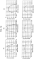
- Fig. 14 is a drawing indicating actual measurement results for the characteristics of emission strength with respect to the azimuth angle of the detection device 100.
- the simulation results, indicated in Fig. 12(A) to Fig. 12(C) of the characteristics of emission strength with respect to the azimuth direction of the detection device 100 are indicated at the upper stage in Fig. 14(A) to Fig. 14(C) and the actual measurement results are indicated at the lower stage.
- the actual measurement results are the characteristics of emission strength with respect to the azimuth direction in a plane with an elevation angle of 10 degrees, as with the simulation results.
- Fig. 13(A) and Fig. 14(A) indicate emission strength for the detection device 100 for which the radius vector R of the curved portion 131 is 7.5 mm and the angle ⁇ of the letter V of the reflector 130 is 120 degrees.
- Fig. 13(B) and Fig. 14(B) indicate emission strength for the detection device 100 for which the radius vector R of the curved portion 131 is 7.5 mm and the angle ⁇ of the letter V of the reflector 130 is 150 degrees.
- Fig. 13(C) and Fig. 14(C) indicate emission strength for the detection device 50 for comparison purposes.
- the detection device 100 can cause a reflected wave to reach a farther distance in a lower left direction and lower right direction of the rear bumper of the vehicle, when compared with the detection device 50 for comparison purposes. It could be confirmed that the detection device 100 can detect the toes of the user in wider ranges in the left-right direction and can operate the electric opener in wider ranges in the left-right direction.
- Fig. 15 is a drawing indicating simulation results obtained in combinations of various radius vectors R and various angles ⁇ of the letter V.
- simulation results of the characteristics of emission strength with respect to the azimuth angle in a plane with an elevation angle of 10 degrees are indicated.
- the radius vector R was set to 1 mm, 2.5 mm, 5.0 mm, 7.5mm, and 10 mm.
- the angle ⁇ of the letter V was set to 150 degrees, 140 degrees, 130 degrees, 120 degrees, and 90 degrees.
- emission strength was higher than the emission strength of the detection device 50 for comparison purposes (see the characteristics at the upper stage in Fig. 12(C) ) on wide-angle sides such as a range of azimuth angles of 40 degrees to 50 degrees and a range of azimuth angles of 130 degrees to 140 degrees, these ranges being equivalent to the lower-left direction and lower-right direction of the rear bumper of the vehicle.
- a blank in the range enclosed by the bold lines A indicates a combination for which simulation was not performed. Also, characteristics for combinations outside the range enclosed by the bold lines A will be omitted here.
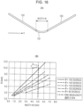
- Fig. 16 is a drawing indicating the width W of the curved portion 131 and a relationship between the width W and the radius vector R.
- the width W of the curved portion 131 will be represented by the length of a segment in which the curved portion 131 is present in the Y direction.
- the combinations in the range enclosed by the bold lines A in Fig. 15 were combinations in which the width W was shorter than or equal to one wavelength of wavelengths at the communication frequency of the transmission and reception device 120.
- the radius vector R tends to increase along with an increase in the width W as the angle ⁇ of the letter V becomes larger.
- the width W equivalent to one wavelength is 5 mm.
- the curved portion 131 by which the width W becomes shorter than or equal to one wavelength of wavelengths at 60.5 GHz, which is the communication frequency of the transmission and reception device 120, a combination of the radius vector R and the width W that is, for example, the width W that becomes shorter than or equal to 5 mm in Fig. 16(B) is suffice.
- a reason for the result like this is that: when the width W is shorter than or equal to one wavelength, the curved portion 131 is narrow, so radio waves are likely to be reflected at the flat plate portions 132 and 133 and expand toward wide-angle sides; however when the width W is longer than one wavelength, the number of radio waves reflected by the curved portion 131 is increased and the number of radio waves reflected toward wide-angle sides by the flat plate portions 132 and 133 is reduced, so the strength of radio waves on the wide-angle sides is lowered.
- a reason is that when the angle ⁇ of the letter V is smaller than or equal to 90 degrees, radio waves reflected at the flat plate portions 132 and 133 are directed to the - X direction rather than to the +X direction, so the strength of radio waves reflected toward the wide-angle sides is lowered. Also, a reason is that when the angle ⁇ of the letter V is greater than or equal to 150 degrees, even when the width W is shorter than or equal to one wavelength, the curved portion 131 approaches a flat surface, so the strength of radio waves reflected toward the wide-angle sides is lowered.
- the angle ⁇ of the letter V is preferably greater than or equal to 90 degrees and the width W of the curved portion 131 is preferably shorter than or equal to one wavelength of wavelengths at the communication frequency of the transmission and reception device 120.
- the reflector 130 has the curved portion 131 and flat plate portions 132 and 133.
- the curved portion 131 is curved at a certain curvature and protrudes toward the same side as the antenna 121 (antenna side).
- the curved portion 131 has the convexly curved surface 131S that reflects radio waves emitted by the antenna 121.
- the convexly curved surface 131S has a shape equivalent to a portion on the outer circumferential surface of a cylinder, the portion being included in a certain azimuth angle ⁇ from the cylindrical axis C.
- the convexly curved surface 131S is inclined toward the same side as the antenna 121 with respect to the upper surface 111 of the circuit board 110.
- the flat plate portions 132 and 133 respectively have the surfaces 132S and 133S that reflect radios emitted by the antenna 121.
- the surfaces 132S and 133S extend from both side portions of the convexly curved surface 131S in the circumferential direction along the upper surface 111 of the circuit board 110, and form a V shape together with the convexly curved surface 131S.
- the convexly curved surface 131S and surfaces 132S and 133S are the reflecting surfaces of the reflector 130.
- the reflector 130 like this which is composed of the curved portion 131 having the convexly curved surface 131S and the flat plate portions 132 and 133 having the surfaces 132S and 133S, has a simple structure and is easy to design.
- the antenna device 100A and detection device 100 having the reflector 130 which has a simple structure and is easy to design. It is also possible to provide an opening/closing unit control system and an occupant detection system that include the antenna device 100A and detection device 100 having the reflector 130, which has a simple structure and is easy to design. Also, since the reflector 130, which has a simple structure and is easy to design, is included, the reach distance of a radio wave reflected at the reflector 130 can be reliably prolonged in desired directions as in ranges of the wide-angle sides described above.
- the convexly curved surface 131S is inclined with respect to the circuit board 110 so that at least part of the convexly curved surface 131S overlaps the antenna 121 in plan view, radio waves emitted by the antenna 121 can be reliably reflected at the reflector 130 and radio waves reflected at the detection target can be reliably reflected at the reflector 130 toward the antenna 121.
- the convexly curved surface 131S and the surfaces 132S and 133S are continuous to each other, radio waves emitted by the antenna 121 and radio waves reflected at the detection target can be evenly reflected. Also, the design and manufacturing of the reflector 130 can be more easily performed.
- the curved portion 131 has a shape in which a flat plate is curved, the design and manufacturing of the curved portion 131 can be more easily performed.
- the flat plate which becomes the curved portion 131, is a flat plate having the flat plate portions 132 and 133 at both ends of a portion that becomes the curved portion 131, the design and manufacturing of the reflector 130 can be more easily performed.
- the width W of the curved portion 131 in the Y-axis direction which is an example of a one-axis direction in which the curved portion 131 and flat plate portions 132 and 133 are arranged in plan view, is shorter than or equal to one wavelength of wavelengths at the communication frequency of the antenna, the reach distance of a radio wave reflected at the reflector 130 can be reliably prolonged in ranges of the wide-angle sides.
- the reach distance of a radio wave reflected at the reflector 130 can be reliably prolonged in ranges of the wide-angle sides.
- the antenna 121 is an antenna that doubles as a transmission antenna for transmitting radio waves and a reception antenna for receiving radio waves, transmission and reception can be performed with one antenna 121. Therefore, the design and manufacturing of the reflector 130 can be more easily performed.
- the antenna 121 has a transmission antenna for transmitting radio waves and a reception antenna for receiving radio waves, the transmission antenna and reception antenna being placed side by side, the design and manufacturing of the reflector 130 can be more easily performed in a structure in which the transmission antenna and reception antenna are different from each other.
- the detection device 100 includes the antenna device 100A, the transmission circuit 122, the reception circuit 123, and the control unit 124, which functions as a detection unit that detects at least one of the presence of the detection target and its behavior according to a signal received by the reception circuit 123. Since the detection device 100 like this includes the reflector 130 composed of the curved portion 131 having the convexly curved surface 131S and the flat plate portions 132 and 133 having the surfaces 132S and 133S, the structure of the detection device 100 is simple and it can be easily designed.
- the transmission circuit 122 and reception circuit 123 are integrally formed in an integrated circuit, it is possible to provide the detection device 100 with a simple structure.
- the antenna 121 and the integrated circuit that implements the transmission circuit 122 and reception circuit 123 are integrally formed, it is possible to provide the detection device 100 with a simpler structure.
- the detection device 100 further includes the lower case 10 and upper case 20 that form a cabinet having an attachment portion attachable at a lower portion of a door of the vehicle, inside the bumper of the vehicle, or in the interior of the room of the vehicle.
- the antenna device 100A, the transmission circuit 122, the reception circuit 123, and the control unit 124, which functions as the detection unit, are stored in the lower case 10 and upper case 20. Therefore, it is possible to provide the detection device 100 f in which the reflector 130, which is easy to design, is packaged.
- control unit 124 which functions as the detection unit, detects at least one of the presence and behavior of the manipulator around the vehicle. Therefore, it is possible to provide the detection device 100 that can be used as an operation detection device for an electric opener for an opening/closing portion of a vehicle.
- the reflector 130 is not limited to a reflector manufactured by bending a metal plate in a flat-plate shape, and may be resinous. When the reflector 130 is resinous, it may be manufactured by plastic molding. Also, the reflector 130 is not limited to a flat-plate shape as described above. If the reflector 130 is an object that has the convexly curved surface 131S and surfaces 132S and 133S, the reflector 130 may have any shape. For example, the reflector 130 may be of box type or the like.
- the transmission and reception device 120 has the antenna 121 that can perform transmission and reception.
- the antenna 121 may have a structure in which the antenna 121 has a transmission antenna that transmits radio waves and a reception antenna that receives radio waves, and the transmission antenna and reception antenna are arranged side by side.
- the transmission and reception device 120 has the antenna 121.
- the antenna 121 may be provided separately from the transmission and reception device 120.
- An aspect has been described above in which the transmission and reception device 120 has the transmission circuit 122, reception circuit 123, and control unit 124.
- the transmission circuit 122, reception circuit 123, and control unit 124 may be provided separately from one another, or the transmission circuit 122 and reception circuit 123 may be separated from the control unit 124.
- the flat plate portions 132 and 133 have a symmetric shape (plane symmetry) in which they are mutual mirror images with respect to a plane that includes the straight line 131B of the curved portion 131 and is parallel to an XZ plane.
- the flat plate portion 132 and flat plate portion 133 may have mutually different shapes.
Landscapes
- Engineering & Computer Science (AREA)
- Radar, Positioning & Navigation (AREA)
- Remote Sensing (AREA)
- Physics & Mathematics (AREA)
- Computer Networks & Wireless Communication (AREA)
- General Physics & Mathematics (AREA)
- Computer Security & Cryptography (AREA)
- Electromagnetism (AREA)
- Aerials With Secondary Devices (AREA)
- Details Of Aerials (AREA)
- Variable-Direction Aerials And Aerial Arrays (AREA)
- Support Of Aerials (AREA)
- Radar Systems Or Details Thereof (AREA)
Abstract
Description
- The present invention relates to an antenna device, a detection device, an opening/closing unit control system, and an occupant detection system.
- There is conventionally a vehicle-mounted radar device that has a millimeter-wave radar and a reflecting mirror that reflects transmission and reception waves of the millimeter-wave radar. The reflecting mirror is a half-truncated cone body the radius of which is longer than the height. A side surface of the half-truncated cone body is a reflecting surface. The reflecting surface is a concavely curved surface formed by curving the generating line of the truncated cone toward the bottom face (see
PTL 1, for example). - PTL 1:
Japanese Unexamined Patent Application Publication No. 2010-154182 - When a reflecting surface is designed so that the distribution of reflected waves becomes more superior, a reflecting surface with the generating line of a half-truncated cone body curved toward the bottom face, as with the reflecting surface of the reflecting mirror of the conventional vehicle-mounted radar device, has a complex shape and is not easy to design.
- Therefore, an object is to provide an antenna device having a reflector that has a simple structure and is easy to design, a detection device, an opening/closing control system, and an occupant detection system.
- An antenna device in an embodiment of the present invention includes: a circuit board; an antenna placed on a surface of the circuit board; and a reflector that is erected on the surface of the circuit board and extends along the surface. The reflector has: a curved portion that has a convexly curved surface, which is curved at a certain curvature and protrudes toward the same side as the antenna, the convexly curved surface reflecting radio waves emitted by the antenna; and a first plane portion and a second plane portion that respectively have a first reflecting surface and a second reflecting surface that extend from both side portions of the convexly curved surface along the surface of the circuit board, form a V shape together with the convexly curved surface in plan view, and reflect radio waves emitted by the antenna. The convexly curved surface has a shape equivalent to a portion on the outer circumferential surface of a cylinder, the portion being included in a certain azimuth angle from a cylindrical axis. The convexly curved surface is inclined toward the same side as the antenna with respect to the circuit board.
- It is possible to provide an antenna device having a reflector that has a simple structure and is easy to design, a detection device, an opening/closing control system, and an occupant detection system.
-
- [
Fig. 1] Fig. 1 is a drawing indicating adetection device 100 in an embodiment. - [
Fig. 2] Fig. 2 is an exploded view of thedetection device 100. - [
Fig. 3] Fig. 3 is a drawing indicating thedetection device 100 and anantenna device 100A. - [
Fig. 4] Fig. 4 is a drawing indicating thedetection device 100 andantenna device 100A. - [
Fig. 5] Fig. 5 is a drawing indicating thedetection device 100 andantenna device 100A. - [
Fig. 6] Fig. 6 is a drawing indicating thedetection device 100 andantenna device 100A. - [
Fig. 7] Fig. 7 is a drawing indicating acurved portion 131. - [
Fig. 8] Fig. 8 is a drawing indicating a cross section along A-A inFig. 4 . - [
Fig. 9] Fig. 9 is a drawing indicating a cross section along B-B inFig. 4 . - [
Fig. 10] Fig. 10 is a drawing indicating an evaluation coordinate system for thedetection device 100. - [
Fig. 11] Fig. 11 is a drawing indicating simulation results for emission strength of thedetection device 100. - [
Fig. 12] Fig. 12 is a drawing indicating simulation results for emission strength of thedetection device 100. - [
Fig. 13] Fig. 13 is a drawing indicating emission strength of thedetection device 100. - [
Fig. 14] Fig. 14 is a drawing indicating actual measurement results for the characteristics of emission strength with respect to the azimuth angle of thedetection device 100. - [
Fig. 15] Fig. 15 is a drawing indicating simulation results obtained in combinations of various radius vectors R and various angles θ of the letter V. - [
Fig. 16] Fig. 16 is a drawing indicating the width W of thecurved portion 131 and a relationship between the width W and the radius vector R. - An embodiment to which an antenna device, a detection device, an opening/closing unit control system, and an occupant detection system in the present invention are applied will be described below. Descriptions will be given below with an XYZ coordinate system defined. A direction (X direction) parallel to the X axis, a direction (Y direction) parallel to the Y axis, and a direction (Z direction) parallel to the Z axis are mutually orthogonal. Also, in the description below, the -Z-direction side may be referred to as the lower side or bottom, and the +Z-direction side may be referred to as the upper side or top, for convenience of explanation. Also, "in plan view" will refer to an XY plane being viewed. Also, in the description below, for easy understanding of the structure, the length, bulkiness, thickness, and the like of each portion may be indicated by being exaggerated. Also, "parallel", "above", "below", and other words will allow incorrectness to the extent that effects of the embodiment are not lost.
-
Fig. 1 is a drawing indicating adetection device 100 in an embodiment. InFig. 1 , an ECU (Electronic Control Unit) 300 is also indicated.Fig. 2 is an exploded view of thedetection device 100. Thedetection device 100 includes alower case 10, anupper case 20, acircuit board 110, a transmission andreception device 120, and areflector 130. The transmission andreception device 120 has anantenna 121, atransmission circuit 122, areception circuit 123, and acontrol unit 124. - The
detection device 100 includes at least thecircuit board 110, transmission andreception device 120, andreflector 130. Anantenna device 100A in the embodiment includes at least thecircuit board 110,antenna 121, andreflector 130. InFig. 2 , therefore, thereference characters 100A are indicated in parentheses for thecircuit board 110,antenna 121, andreflector 130. - The
lower case 10 andupper case 20, which are an example of a cabinet, become a case having a sealed internal space by being aligned and engaged. In the internal space in the case formed with thelower case 10 andupper case 20, thecircuit board 110, transmission andreception device 120, andreflector 130 are stored. Like this, with thedetection device 100, thecircuit board 110, transmission andreception device 120, andreflector 130 are packaged by being stored in thelower case 10 andupper case 20. - As an example, the
upper case 20 hasengagement portions 21,screw holes 22, and aconnector 23. Theengagement portions 21 andscrew holes 22 are an example of an attachment portion that can attach the case formed with thelower case 10 andupper case 20 at a lower portion of a door of a vehicle, inside the bumper, or in the interior of the room of the vehicle. Theconnector 23 has terminals to be connected to the transmission andreception device 120 through thecircuit board 110. Theconnector 23 is connected to the ECU 300 in the vehicle through, for example, LIN (Local Interconnect Network) or CAN (Controller Area Network) mounted in the vehicle. Thus, thedetection device 100 is connected to theECU 300 through theconnector 23. - As an example, the
detection device 100 like this can be used as an operation detection device for an electric opener for an opening/closing portion of the trunk lid, the rear gate, a slide door, or the like of a vehicle. In this case, thedetection device 100 detects the presence or motion of the toes of the user of the vehicle below the rear bumper. The user who inserts the toes below the rear bumper is an example of a manipulator present around a vehicle. - The electric opener is a device that performs unlocking of a lock and driving of an actuator that opens and closes an opening/closing portion of a trunk lid, a rear gate, a slide door, or the like. Here, when the
ECU 300 is a control unit that controls the opening and closing of an opening/closing portion of a vehicle according to a detection result of thedetection device 100, a system including thedetection device 100 andECU 300 is an opening/closing control system. Also, when theECU 300 is an occupant detection unit that detects the presence or absence of an occupant in the room of a vehicle according to a detection result of thedetection device 100, a system including thedetection device 100 andECU 300 is an occupant detection system. - When the
detection device 100 is used as an operation detection device for an electric opener for the trunk lid or rear gate of a vehicle, thedetection device 100 is provided, as an example, inside the rear bumper of the vehicle at the center in the width direction of the vehicle. In this case, the +X direction is the vertically downward direction, the -X direction is the vertically upward direction, the +Y direction is on the right side in the travel direction of the vehicle, the -Y direction is on the left side in the travel direction of the vehicle, the +Z direction is the backward of the vehicle, and the +Z direction is the forward of the vehicle. Thedetection device 100 emits radio waves in the +X direction, receives reflected waves, and detects, in the +X direction, the presence of a detection target or the behavior of the detection target. - An aspect will be described below in which, as an example, the
detection device 100 is provided inside the rear bumper of a vehicle and detects the presence or motion of the toes of the user who is going to operate the electric opener of the trunk lid or rear gate. That is, in the description below, the detection target of thedetection device 100 is the toes of the user, as an example. - The
detection device 100 detects, in the +X direction, the presence of the detection target or the behavior of the detection target by emitting radio waves in the +X direction and receiving reflected waves. A timing to receive a reflected wave differs between a case in which the toes of the user, which are the detection target, are not present below thedetection device 100 and a case in which the toes are present. Therefore, thedetection device 100 detects at least one of the presence of the toes and a behavior in which the toes have been inserted below thedetection device 100. - Next, details of the structures of the
circuit board 110, transmission andreception device 120, andreflector 130 will be described. Here, the structures will be described by usingFig. 3 to Fig. 6 , in addition toFig. 1 andFig. 2 .Fig. 3 to Fig. 6 are drawings indicating thedetection device 100 andantenna device 100A. InFig. 3 to Fig. 6 , thecircuit board 110, transmission andreception device 120, andreflector 130 are indicated. - The
circuit board 110 has a shape matching the shapes of thelower case 10 andupper case 20 in plan view, as indicated inFig. 2 to Fig. 4 . Thecircuit board 110 is, for example, is a wiring board complying with the FR4 (Flame Retardant type 4) standard or the like. The transmission andreception device 120 andreflector 130 are mounted on theupper surface 111 of thecircuit board 110. The control unit 124 (seeFig. 2 ) of the transmission andreception device 120 is connected to the terminals of the connector 23 (seeFig. 1 andFig. 2 ) through wires on thecircuit board 110. Thecircuit board 110 is fixed in the interior of theupper case 20 with screws or the like, as an example. - The transmission and
reception device 120 has theantenna 121,transmission circuit 122,reception circuit 123, andcontrol unit 124 as indicated inFig. 2 by being enlarged, and is mounted on theupper surface 111 of thecircuit board 110 as indicated inFig. 2 to Fig. 6 . Portions of thetransmission circuit 122,reception circuit 123, andcontrol unit 124 in the transmission andreception device 120 are implemented as a so-called IC (Integrated Circuit) chip. - The
antenna 121 is provided on the upper surface of the IC chip and is connected to thetransmission circuit 122 andreception circuit 123. Theantenna 121 is a patch antenna as an example, and is an antenna that doubles as a transmission antenna for transmitting radio waves and a reception antenna for receiving radio waves. Theantenna 121 can transmit and receive millimeter-waves at 60.5 GHz, as an example. - The
transmission circuit 122 andreception circuit 123 are integrally formed in an analog integrated circuit included in the IC chip. Also, thetransmission circuit 122 andreception circuit 123 are connected to thecontrol unit 124, and their operations are controlled by thecontrol unit 124. Thetransmission circuit 122 outputs a transmission signal to theantenna 121 in response to a transmission command output from thecontrol unit 124. Thereception circuit 123 receives a reflected wave, which is a transmission signal reflected at the detection target. - The
control unit 124 represents functions implemented by a computer included in the IC chip. Thecontrol unit 124 has functions used as a detection unit that detects at least one of the presence and behavior of the detection target according to a signal received by thereception circuit 123. - The
reflector 130 is erected on theupper surface 111 of thecircuit board 110 as indicated inFig. 3 to Fig. 6 . Erection on theupper surface 111 refers to provision in an erected state on theupper surface 111 or provision in a standing state on theupper surface 111. Thereflector 130 is provided so as to be inclined with respect to theupper surface 111. Details of this will be described later. - The
reflector 130 has acurved portion 131,flat plate portions portions 134, and engagingportions 135. Theflat plate portion 132 is an example of a first plane portion, and theflat plate portion 133 is an example of a second plane portion. Thecurved portion 131 andflat plate portions upper surface 111 of thecircuit board 110. Thereflector 130 reflects radio waves emitted by theantenna 121 toward the +X-direction side. Also, thereflector 130 reflects radio waves reflected on the detection target toward theantenna 121. - Since the
reflector 130 is provided in the interior of the rear bumper of the vehicle at the center of the width direction of the vehicle, thereflector 130 demanded to enable the reflected wave to reach a farther distance in a lower left direction and lower right direction of the rear bumper of the vehicle. This is to enable the toes of the user to be detected in a wider range in the left-right direction. - The distance from the
reflector 130 to a toe is longer in a case in which the toe is positioned immediately below thereflector 130 than in a case in which the toe is at a lower left position and at a lower right position. Therefore, thereflector 130 is structured so that it can reflect radio waves farther in a lower left direction, which is on the -Y-direction side in the +X direction and in a lower right direction, which is on the + Y-direction side in the +X direction. - To prolong the reach distance on the -Y-direction side in the +X direction (in a lower left direction) and on the + Y-direction side in the +X direction (in a lower right direction), highly precise design to prolong the reach distance is demanded to be possible. To achieve this, the
reflector 130 of theantenna device 100A anddetection device 100 in this embodiment has a relatively simple structure. - The
curved portion 131 has a convexlycurved surface 131S, which is curved at a certain curvature and protrudes toward the same side as the transmission andreception device 120 having the antenna 121 (seeFig. 2 ). The convexlycurved surface 131S is the reflecting surface of thecurved portion 131. Thecurved portion 131 has a shape in which a flat plate is curved. The convexlycurved surface 131S has a shape equivalent to a portion on the outer circumferential surface of a cylinder, the portion being included in a certain azimuth angle from a cylindrical axis. Thecurved portion 131 is inclined toward the same side as the transmission andreception device 120 having the antenna 121 (seeFig. 2 ), with respect to theupper surface 111 of thecircuit board 110. - Here, to explain the shape of the
curved portion 131,Fig. 7 to Fig. 9 will be used in addition toFig. 3 to Fig. 6 .Fig. 7 is a drawing indicating thecurved portion 131. InFig. 7 , only thecurved portion 131 in thereflector 130 is extracted and indicated; and acylinder 1 including thecurved portion 131, thecylinder 1 being vertical, is indicated.Fig. 8 is a drawing indicating a cross section along A-A inFig. 4 .Fig. 9 is a drawing indicating a cross section along B-B inFig. 4 . - As indicated in
Fig. 7(A) , thecurved portion 131 is a portion on thecylinder 1 having a radius vector R and a cylindrical axis C, the portion being included within an azimuth angle ϕ with respect to the cylindrical axis C. The azimuth angle ϕ is an example of a certain azimuth angle. Thecurved portion 131 has a vertex 131A1 of an arc, the vertex 131A1 being at the upper end of the convexlycurved surface 131S, a vertex 131A2 of the arc, the vertex 131A2 being at the lower end of the convexlycurved surface 131S, and astraight line 131B linking the vertex 131A1 and vertex 131A2 together. Thestraight line 131B is positioned on the convexlycurved surface 131S and is parallel to the cylindrical axis C. Thestraight line 131B is a straight line equivalent to the generating line of thecylinder 1. - As indicated in
Fig. 7(B) , thecurved portion 131 is placed on theupper surface 111 so that thestraight line 131B linking the vertex 131A1 and vertex 131A2 together is positioned on a plane parallel to an XZ plane and passing through thecenter 120C of the upper surface of the transmission andreception device 120 and that thestraight line 131B is inclined toward the same side as the transmission andreception device 120. Since thestraight line 131B is inclined toward the same side as the transmission andreception device 120, the convexlycurved surface 131S is inclined toward the same side as the transmission andreception device 120. Thecenter 120C is equivalent to the center of the surface of the antenna 121 (seeFig. 2 ). - The
curved portion 131 is inclined so that the angle formed by theupper surface 111 and thestraight line 131B linking the vertex 131A1 and vertex 131A2 together becomes an angle α on a plane parallel to an XZ plane and passing through thecenter 120C of the transmission andreception device 120. Although the convexlycurved surface 131S has a shape in which the convexlycurved surface 131S is curved in the circumferential direction as with the outer circumferential surface of thecylinder 1, but is not curved in a direction parallel to the cylindrical axis C andstraight line 131B. - In this embodiment, the angle α is 52 degrees as an example, as indicated in
Fig. 8 . Thecurved portion 131 like this is relatively easy to design. Thecurved portion 131 can be manufactured by bending a flat plate to a radius R of curvature along the cylindrical axis C, which is vertical. Incidentally, the angle α is not limited to 52 degrees. The angle α is an acute angle (an angle greater than 0 degree and smaller than 90 degrees). - As indicated in
Fig. 4 , thecurved portion 131 overlaps the transmission andreception device 120 in plan view, as an example. Here, an aspect is indicated in which thecurved portion 131 overlaps the whole of the transmission andreception device 120. However, thecurved portion 131 preferably overlaps at least part of the transmission andreception device 120 in plan view. This is because radio waves emitted from the antenna 121 (seeFig. 2 ) of the transmission andreception device 120 can be efficiently reflected. Incidentally, when, for example, theantenna 121 emits radio waves toward the same side as thecurved portion 131 with respect to the vertically upward direction, thecurved portion 131 may not overlap the transmission andreception device 120 in plan view. - Both of the
flat plate portions surfaces Fig. 3 ,Fig. 5 , andFig. 6 . Thesurfaces flat plate portions surface 132S is an example of a first reflecting surface, and thesurface 133S is an example of a second reflecting surface. - The
surfaces curved surface 131S in the circumferential direction along theupper surface 111 of thecircuit board 110, and form a V shape together with the convexlycurved surface 131S in plan view as indicated by the broken lines inFig. 4 . The angle (interior angle) θ of the V shape formed by thesurfaces - The
flat plate portion 132 is provided continuously from the side portion of thecurved portion 131 on the -Y-direction side in the circumferential direction, and theflat plate portion 133 is provided continuously from the side portion of thecurved portion 131 on the +Y-direction side in the circumferential direction. Therefore, thesurface 132S is a surface continuous from the end of the convexly curved surface 1315 on the -Y-direction side, and thesurface 133S is a surface continuous from the end of the convexlycurved surface 131S on the +Y -direction side. - Therefore, when the cross section, of the
flat plate portion 132, taken along a plane parallel to an XZ plane is viewed as indicated inFig. 9 , the angle formed by thesurface 132S andupper surface 111 is α, so the angle is equal to the angle α formed by theupper surface 111 and thestraight line 131B of thecurved portion 131. This is because in an XZ plane, theflat plate portion 132 is inclined at the same angle as thecurved portion 131 with respect to theupper surface 111. Here, the angle α is 52 degrees, as an example. - Also, since the
flat plate portion 132 andflat plate portion 133 have a symmetric shape (plane symmetry), in which they are mutual mirror images, with respect to a plane that includes thestraight line 131B of thecurved portion 131 and is parallel to an XZ plane, when the cross section, of theflat plate portion 133, taken along a plane parallel to an XZ plane is viewed, the angle formed by thesurface 133S andupper surface 111 is α, so the angle is equal to the angle α formed by theupper surface 111 and thestraight line 131B of thecurved portion 131. - The two fixing
portions 134 are a portion extending from an end of theflat plate portion 132 on the -Y-direction side and a portion extending from an end of theflat plate portion 133 on the +Y-direction side. The fixingportions 134 extend in the -X direction. The fixingportions 134 are provided to stably fix thereflector 130 on the upper surface of thecircuit board 110, and haveconvex portions 134A (seeFig. 6 ) protruding downward. Theconvex portions 134A are inserted into through-holes passing through thecircuit board 110 in the thickness direction (Z direction), and are fixed to thecircuit board 110 with an adhesive or the like. - The two
engaging portions 135 are portions extending from the lower ends of theflat plate portion 132 andflat plate portion 133. The engagingportion 135 is inserted into a through-hole passing through thecircuit board 110 in the thickness direction (Z direction), and is fixed to thecircuit board 110 with an adhesive or the like. - With the
reflector 130 as described above, a direction in which the +X direction is viewed from thevertexes 131A 1 and 131A2 in plan view is the direction of the front of thereflector 130 and is the direction of the fronts of theantenna device 100A anddetection device 100. - The
reflector 130 having thecurved portion 131,flat plate portions portions 134, and engagingportions 135 as described above can be manufactured by, for example, bending a metal plate obtained by performing punching processing to stamp a sheet metal to the radius R of curvature along the cylindrical axis C, which is vertical. The metal plate may be made of, for example, aluminum. -
Fig. 10 is a drawing indicating an evaluation coordinate system for thedetection device 100. Since thedetection device 100 includes theantenna device 100A, evaluation results for thedetection device 100 will be described below. Descriptions will be given below, assuming that, as indicated inFig. 10 , the XYZ coordinate system is the same as the XYZ coordinate system indicated inFig. 1 to Fig. 9 and that the origin matches thecenter 120C (seeFig. 7(B) ) on the upper surface of the transmission andreception device 120. - The evaluation coordinate system is a polar coordinate system. The azimuth angle indicates an angle in a direction indicated by an arrow with the -Y direction taken as a reference (0 degree). Therefore, the azimuth angle in the +X direction is 90 degrees and the azimuth angle in the +Y direction is 180 degrees. The azimuth angle in the -X direction is 270 degrees and is also -90 degrees. The elevation angle indicates an angle in a direction indicated by an arrow with the +X direction taken as a reference (0 degree). Therefore, the elevation angle in the +Z direction is 90 degrees and the azimuth angle in the -Z direction is - 90.
-
Fig. 11 is a drawing indicating simulation results for emission strength of thedetection device 100. InFig. 11(A) to Fig. 11(C) , the horizontal axis indicates the azimuth angle (degrees) and the vertical axis indicates the elevation angle (degrees). InFig. 11(A) to Fig. 11(C) , it is represented that the brighter, the higher emission strength is, and that the darker, the lower emission strength is. Also, adetection device 50 for comparison purposes is indicated below the simulation result of emission strength inFig. 11(C) . Thedetection device 50 for comparison purposes has areflector 53 for which a reflecting surface equivalent to the convexlycurved surface 131S of thecurved portion 131 of thereflector 130 and to thesurfaces flat plate portions -
Fig. 12 is a drawing indicating simulation results for emission strength of thedetection device 100. InFig. 12(A) to Fig. 12(C) , the characteristics of emission strength (dB) with respect to the azimuth angle in a plane with an elevation angle of 10 degrees are indicated at the upper stage and the characteristics of emission strength with respect to the elevation angle in an XZ plane are indicated at the lower stage. An XZ plane is a plane with an azimuth angle of 90 degrees. -
Fig. 11(A) andFig. 12(A) indicate emission strength for a simulation model for which the radius vector R of thecurved portion 131 is 7.5 mm and the angle θ of the letter V of thereflector 130 is 120 degrees.Fig. 11(B) andFig. 12(B) indicate emission strength for a simulation model for which the radius vector R of thecurved portion 131 is 7.5 mm and the angle θ of the letter V of thereflector 130 is 150 degrees. Also,Fig. 11(C) andFig. 12(C) indicate emission strength in simulation results for thedetection device 50 for comparison purposes. - When
Fig. 11(A) andFig. 12(A) as well asFig. 11(B) andFig. 12(B) are compared withFig. 11(C) andFig. 12(C) , it is found for the azimuth angle that emission strength is improved in a range from 40 degrees to 50 degrees and in a range from 130 degrees to 140 degrees. Since thedetection device 100 is provided in the interior of the rear bumper of a vehicle at the center in the width direction of the vehicle, the range of the azimuth angle from 40 degrees to 50 degrees and the range of the azimuth angle from 130 degrees to 140 degrees are respectively equivalent to a lower left direction and lower right direction of the rear bumper of the vehicle. The range of the azimuth angle from 40 degrees to 50 degrees and the range of the azimuth angle from 130 degrees to 140 degrees are a wide-angle range in angles at which radio waves that are emitted from theantenna 121 and are reflected by thereflector 130 propagate in an XY plane, the wide-angle range being a range of wide angles with respect to the direction at an azimuth angle of 90 degrees. The direction at an azimuth angle of 90 degrees is the direction of the front of thereflector 130. The wide-angle range is a range in which angles with respect to direction of the front of thereflector 130 are relatively large. - Also, as for characteristics for the elevation angle, the
detection device 100 and thedetection device 50 for comparison purposes exhibited equivalent emission strength, as seen from the characteristics at the lower stage inFig. 12(A), Fig. 12(B) , andFig. 11(C) . - Due to this, it was found that the
detection device 100 can cause a reflected wave to reach a farther distance in a lower left direction and lower right direction of the rear bumper of the vehicle, when compared with thedetection device 50 for comparison purposes. Thedetection device 100 can detect the toes of the user in a wider range in the left-right direction. -
Fig. 13 is a drawing indicating emission strength of thedetection device 100. InFig. 13 , for comparison of actual measurement results with simulation results, the simulation results indicated inFig. 11(A) to Fig. 11(C) are indicated at the upper stage inFig. 13(A) to Fig. 13(C) and the actual measurement results are indicated at the lower stage. - In
Fig. 13(A) to Fig. 13(C) , the horizontal axis indicates the azimuth angle (degrees) and the vertical axis indicates the elevation angle (degrees). InFig. 13(A) to Fig. 13(C) , it is represented that the brighter, the higher emission strength is and that the darker, the lower emission strength is. -
Fig. 14 is a drawing indicating actual measurement results for the characteristics of emission strength with respect to the azimuth angle of thedetection device 100. InFig. 14 , for comparison of actual measurement results with simulation results, the simulation results, indicated inFig. 12(A) to Fig. 12(C) , of the characteristics of emission strength with respect to the azimuth direction of thedetection device 100 are indicated at the upper stage inFig. 14(A) to Fig. 14(C) and the actual measurement results are indicated at the lower stage. The actual measurement results are the characteristics of emission strength with respect to the azimuth direction in a plane with an elevation angle of 10 degrees, as with the simulation results. -
Fig. 13(A) andFig. 14(A) indicate emission strength for thedetection device 100 for which the radius vector R of thecurved portion 131 is 7.5 mm and the angle θ of the letter V of thereflector 130 is 120 degrees.Fig. 13(B) andFig. 14(B) indicate emission strength for thedetection device 100 for which the radius vector R of thecurved portion 131 is 7.5 mm and the angle θ of the letter V of thereflector 130 is 150 degrees. Also,Fig. 13(C) andFig. 14(C) indicate emission strength for thedetection device 50 for comparison purposes. - When the simulation results at the upper stage in
Fig. 13(A) to Fig. 13(C) and the actual measurement results at the lower stage are compared, it can be confirmed that the simulation results and actual measurement results represent similar results in thedetection device 100 with the angle θ of the letter V being 120 degrees, thedetection device 100 with the angle θ of the letter V being 150 degrees, and thedetection device 50 for comparison purposes. - Also, the actual measurement results in
Fig. 13(A) andFig. 14(A) as well asFig. 13(B) andFig. 14(B) are compared with the actual measurement results inFig. 13(C) andFig. 14(C) , it is found that emission strength is improved in a range from 40 degrees to 50 degrees and in a range from 130 degrees to 140 degrees. - From the actual measurement results like this, it could be confirmed that the
detection device 100 can cause a reflected wave to reach a farther distance in a lower left direction and lower right direction of the rear bumper of the vehicle, when compared with thedetection device 50 for comparison purposes. It could be confirmed that thedetection device 100 can detect the toes of the user in wider ranges in the left-right direction and can operate the electric opener in wider ranges in the left-right direction. -
Fig. 15 is a drawing indicating simulation results obtained in combinations of various radius vectors R and various angles θ of the letter V. InFig. 15 , simulation results of the characteristics of emission strength with respect to the azimuth angle in a plane with an elevation angle of 10 degrees are indicated. The radius vector R was set to 1 mm, 2.5 mm, 5.0 mm, 7.5mm, and 10 mm. The angle θ of the letter V was set to 150 degrees, 140 degrees, 130 degrees, 120 degrees, and 90 degrees. - In combinations in the range enclosed by bold lines A, emission strength was higher than the emission strength of the
detection device 50 for comparison purposes (see the characteristics at the upper stage inFig. 12(C) ) on wide-angle sides such as a range of azimuth angles of 40 degrees to 50 degrees and a range of azimuth angles of 130 degrees to 140 degrees, these ranges being equivalent to the lower-left direction and lower-right direction of the rear bumper of the vehicle. Incidentally, a blank in the range enclosed by the bold lines A indicates a combination for which simulation was not performed. Also, characteristics for combinations outside the range enclosed by the bold lines A will be omitted here. -
Fig. 16 is a drawing indicating the width W of thecurved portion 131 and a relationship between the width W and the radius vector R. As indicated inFig. 16(A) , the width W of thecurved portion 131 will be represented by the length of a segment in which thecurved portion 131 is present in the Y direction. When the width W like this was used, the combinations in the range enclosed by the bold lines A inFig. 15 were combinations in which the width W was shorter than or equal to one wavelength of wavelengths at the communication frequency of the transmission andreception device 120. - As indicated in
Fig. 16(B) , in the relationship between the width W and the radius vector R, the radius vector R tends to increase along with an increase in the width W as the angle θ of the letter V becomes larger. At 60.5 GHz, the width W equivalent to one wavelength is 5 mm. The relationship between the radius vector R and the width W on the left side with respect to the bold line indicated by width W = 5 mm represents a combination of the width W and radius vector R in which emission strength is increased on the wide-angle sides. Therefore, to design thecurved portion 131 by which the width W becomes shorter than or equal to one wavelength of wavelengths at 60.5 GHz, which is the communication frequency of the transmission andreception device 120, a combination of the radius vector R and the width W that is, for example, the width W that becomes shorter than or equal to 5 mm inFig. 16(B) is suffice. - Incidentally, on wide-angle sides such as a range in which azimuth angles are from 40 degrees to 50 degrees and a range from 130 degrees to 140 degrees, a case in which emission strength becomes higher when compared with the
detection device 50 for comparison purposes was not recognized when the width W is longer than one wavelength of wavelengths at the communication frequency of the transmission andreception device 120, when the angle θ of the letter V is greater than 150 degrees, and when the angle θ of the letter V is smaller than 90 degrees. - A reason for the result like this is that: when the width W is shorter than or equal to one wavelength, the
curved portion 131 is narrow, so radio waves are likely to be reflected at theflat plate portions curved portion 131 is increased and the number of radio waves reflected toward wide-angle sides by theflat plate portions flat plate portions curved portion 131 approaches a flat surface, so the strength of radio waves reflected toward the wide-angle sides is lowered. - From this, it was found that, to increase emission strength on wide-angle sides such as a range of azimuth angles of 40 degrees to 50 degrees and a range of azimuth angles of 130 degrees to 140 degrees, these ranges being equivalent to the lower-left direction and lower-right direction of the rear bumper of the vehicle, the angle θ of the letter V is preferably greater than or equal to 90 degrees and the width W of the
curved portion 131 is preferably shorter than or equal to one wavelength of wavelengths at the communication frequency of the transmission andreception device 120. - As described above, the
reflector 130 has thecurved portion 131 andflat plate portions curved portion 131 is curved at a certain curvature and protrudes toward the same side as the antenna 121 (antenna side). Thecurved portion 131 has the convexlycurved surface 131S that reflects radio waves emitted by theantenna 121. The convexlycurved surface 131S has a shape equivalent to a portion on the outer circumferential surface of a cylinder, the portion being included in a certain azimuth angle ϕ from the cylindrical axis C. The convexlycurved surface 131S is inclined toward the same side as theantenna 121 with respect to theupper surface 111 of thecircuit board 110. - Also, the
flat plate portions surfaces antenna 121. Thesurfaces curved surface 131S in the circumferential direction along theupper surface 111 of thecircuit board 110, and form a V shape together with the convexlycurved surface 131S. The convexlycurved surface 131S and surfaces 132S and 133S are the reflecting surfaces of thereflector 130. - The
reflector 130 like this, which is composed of thecurved portion 131 having the convexlycurved surface 131S and theflat plate portions surfaces - Therefore, it is possible to provide the
antenna device 100A anddetection device 100 having thereflector 130, which has a simple structure and is easy to design. It is also possible to provide an opening/closing unit control system and an occupant detection system that include theantenna device 100A anddetection device 100 having thereflector 130, which has a simple structure and is easy to design. Also, since thereflector 130, which has a simple structure and is easy to design, is included, the reach distance of a radio wave reflected at thereflector 130 can be reliably prolonged in desired directions as in ranges of the wide-angle sides described above. - Also, since the convexly
curved surface 131S is inclined with respect to thecircuit board 110 so that at least part of the convexlycurved surface 131S overlaps theantenna 121 in plan view, radio waves emitted by theantenna 121 can be reliably reflected at thereflector 130 and radio waves reflected at the detection target can be reliably reflected at thereflector 130 toward theantenna 121. - Also, since the convexly
curved surface 131S and thesurfaces antenna 121 and radio waves reflected at the detection target can be evenly reflected. Also, the design and manufacturing of thereflector 130 can be more easily performed. - Since the
curved portion 131 has a shape in which a flat plate is curved, the design and manufacturing of thecurved portion 131 can be more easily performed. - Also, since the flat plate, which becomes the
curved portion 131, is a flat plate having theflat plate portions curved portion 131, the design and manufacturing of thereflector 130 can be more easily performed. - Also, since the width W of the
curved portion 131 in the Y-axis direction, which is an example of a one-axis direction in which thecurved portion 131 andflat plate portions reflector 130 can be reliably prolonged in ranges of the wide-angle sides. - Also, since the angle formed by the
surfaces reflector 130 can be reliably prolonged in ranges of the wide-angle sides. - Also, since the
antenna 121 is an antenna that doubles as a transmission antenna for transmitting radio waves and a reception antenna for receiving radio waves, transmission and reception can be performed with oneantenna 121. Therefore, the design and manufacturing of thereflector 130 can be more easily performed. - Also, since the
antenna 121 has a transmission antenna for transmitting radio waves and a reception antenna for receiving radio waves, the transmission antenna and reception antenna being placed side by side, the design and manufacturing of thereflector 130 can be more easily performed in a structure in which the transmission antenna and reception antenna are different from each other. - The
detection device 100 includes theantenna device 100A, thetransmission circuit 122, thereception circuit 123, and thecontrol unit 124, which functions as a detection unit that detects at least one of the presence of the detection target and its behavior according to a signal received by thereception circuit 123. Since thedetection device 100 like this includes thereflector 130 composed of thecurved portion 131 having the convexlycurved surface 131S and theflat plate portions surfaces detection device 100 is simple and it can be easily designed. - Also, since the
transmission circuit 122 andreception circuit 123 are integrally formed in an integrated circuit, it is possible to provide thedetection device 100 with a simple structure. - Also, since the
antenna 121 and the integrated circuit that implements thetransmission circuit 122 andreception circuit 123 are integrally formed, it is possible to provide thedetection device 100 with a simpler structure. - The
detection device 100 further includes thelower case 10 andupper case 20 that form a cabinet having an attachment portion attachable at a lower portion of a door of the vehicle, inside the bumper of the vehicle, or in the interior of the room of the vehicle. Theantenna device 100A, thetransmission circuit 122, thereception circuit 123, and thecontrol unit 124, which functions as the detection unit, are stored in thelower case 10 andupper case 20. Therefore, it is possible to provide the detection device 100 f in which thereflector 130, which is easy to design, is packaged. - Also, the
control unit 124, which functions as the detection unit, detects at least one of the presence and behavior of the manipulator around the vehicle. Therefore, it is possible to provide thedetection device 100 that can be used as an operation detection device for an electric opener for an opening/closing portion of a vehicle. - Incidentally, an aspect has been described above in which the
curved portion 131 andflat plate portions reflector 130 are manufactured by bending a metal plate in a flat-plate shape, as an example. However, thereflector 130 is not limited to a reflector manufactured by bending a metal plate in a flat-plate shape, and may be resinous. When thereflector 130 is resinous, it may be manufactured by plastic molding. Also, thereflector 130 is not limited to a flat-plate shape as described above. If thereflector 130 is an object that has the convexlycurved surface 131S and surfaces 132S and 133S, thereflector 130 may have any shape. For example, thereflector 130 may be of box type or the like. - Also, an aspect has been described above in which the transmission and
reception device 120 has theantenna 121 that can perform transmission and reception. However, theantenna 121 may have a structure in which theantenna 121 has a transmission antenna that transmits radio waves and a reception antenna that receives radio waves, and the transmission antenna and reception antenna are arranged side by side. - Also, an aspect has been described above in which the transmission and
reception device 120 has theantenna 121. However, theantenna 121 may be provided separately from the transmission andreception device 120. An aspect has been described above in which the transmission andreception device 120 has thetransmission circuit 122,reception circuit 123, andcontrol unit 124. However, thetransmission circuit 122,reception circuit 123, andcontrol unit 124 may be provided separately from one another, or thetransmission circuit 122 andreception circuit 123 may be separated from thecontrol unit 124. - Also, an aspect has been described above in which the
flat plate portions straight line 131B of thecurved portion 131 and is parallel to an XZ plane. However, if theflat plate portion 132 andflat plate portion 133 have thesurfaces surfaces flat plate portion 132 andflat plate portion 133 may have mutually different shapes. - So far, the antenna device, detection device, opening/closing unit control system, and occupant detection system in an exemplary embodiment in the present invention have been described. However, the present invention is not limited to specifically disclosed embodiments. Various variations and modifications are possible without departing from the scope of the claims.
-
- 100 detection device
- 100A antenna device
- 110 circuit board
- 120 transmission and reception device
- 120C center
- 121 antenna
- 122 transmission circuit
- 123 reception circuit
- 130 reflector
- 131 curved portion
- 131S convexly curved surface
- 131A1 vertex
- 131A2 vertex
- 131B straight line
- 132, 133 flat plate portion
- 132S, 133S surface
Claims (16)
- An antenna device comprising:a circuit board;an antenna placed on a surface of the circuit board; anda reflector that is erected on the surface of the circuit board and extends along the surface; whereinthe reflector hasa curved portion that has a convexly curved surface, which is curved at a certain curvature and protrudes toward the same side as the antenna, the convexly curved surface reflecting a radio wave emitted by the antenna, anda first plane portion and a second plane portion that respectively have a first reflecting surface and a second reflecting surface that extend from both side portions of the convexly curved surface along the surface of the circuit board, form a V shape together with the convexly curved surface in plan view, and reflect a radio wave emitted by the antenna,the convexly curved surface has a shape equivalent to a portion on an outer circumferential surface of a cylinder, the portion being included in a certain azimuth angle from a cylindrical axis, andthe convexly curved surface is inclined toward the same side as the antenna with respect to the circuit board.
- The antenna device according to Claim 1, wherein the convexly curved surface is inclined with respect to the circuit board so that at least part of the convexly curved surface overlaps the antenna in plan view.
- The antenna device according to Claim 1 or 2,
wherein the convexly curved surface and the first reflecting surface and second reflecting surface are continuous to each other. - The antenna device according to any one of Claims 1 to 3, wherein the curved portion has a shape in which a flat plate is curved.
- The antenna device according to Claim 4, wherein the flat plate is a flat plate having the first plane portion and the second plane portion at both ends of a portion that becomes the curved portion.
- The antenna device according to any one of Claims 1 to 5, wherein a width of the curved portion in a one-axis direction in which the curved portion, the first plane portion, and the second plane portion are arranged in plan view, is shorter than or equal to one wavelength of wavelengths at a communication frequency of the antenna.
- The antenna device according to any one of Claims 1 to 6, wherein an angle formed by the first reflecting surface and the second reflecting surface is greater than or equal to 90 degrees in plan view.
- The antenna device according to any one of Claims 1 to 7, wherein the antenna is an antenna that doubles as a transmission antenna for transmitting a radio wave and a reception antenna for receiving a radio wave.
- The antenna device according to any one of Claims 1 to 7, wherein the antenna has a transmission antenna for transmitting a radio wave and a reception antenna for receiving a radio wave, the transmission antenna and the reception antenna being placed side by side.
- A detection device comprising:the antenna device according to any one of Claims 1 to 9;a transmission circuit that outputs a transmission signal to the antenna;a reception circuit that receives a reflected wave, which is the transmission signal reflected at a detection target; anda detection unit that detects at least one of presence and behavior of the detection target according to a signal received by the reception circuit.
- The detection device according to Claim 10, wherein the transmission circuit and the reception circuit are integrally formed in an integrated circuit.
- The detection device according to Claim 11, wherein the antenna and the integrated circuit are integrally formed.
- The detection device according to any one of Claims 10 to 12, further comprising a cabinet having an attachment portion attachable at a lower portion of a door of a vehicle, inside a bumper of the vehicle, or in an interior of a room of the vehicle, wherein
the antenna device, the transmission circuit, the reception circuit, and the detection unit are stored in the cabinet. - The detection device according to Claim 13, wherein the detection unit detects at least one of presence and behavior of a manipulator around the vehicle.
- An opening/closing unit control system comprising:the detection device according to Claim 14; anda control unit that controls opening and closing of an opening/closing portion of the vehicle according to a detection result of the detection unit.
- An occupant detection system comprising;the detection device according to Claim 14; andan occupant detection unit that detects presence or absence of an occupant in a room of a vehicle according to a detection result of the detection unit.
Applications Claiming Priority (2)
| Application Number | Priority Date | Filing Date | Title |
|---|---|---|---|
| JP2021020998 | 2021-02-12 | ||
| PCT/JP2021/042849 WO2022172553A1 (en) | 2021-02-12 | 2021-11-22 | Antenna device, detecting device, opening and closing unit control system, and passenger detecting system |
Publications (3)
| Publication Number | Publication Date |
|---|---|
| EP4293830A1 true EP4293830A1 (en) | 2023-12-20 |
| EP4293830A4 EP4293830A4 (en) | 2025-01-01 |
| EP4293830B1 EP4293830B1 (en) | 2026-05-06 |
Family
ID=82838602
Family Applications (1)
| Application Number | Title | Priority Date | Filing Date |
|---|---|---|---|
| EP21925114.7A Active EP4293830B1 (en) | 2021-02-12 | 2021-11-22 | Detecting device and opening and closing unit control system, and passenger detecting system |
Country Status (4)
| Country | Link |
|---|---|
| US (1) | US12493111B2 (en) |
| EP (1) | EP4293830B1 (en) |
| JP (1) | JP7451776B2 (en) |
| WO (1) | WO2022172553A1 (en) |
Families Citing this family (1)
| Publication number | Priority date | Publication date | Assignee | Title |
|---|---|---|---|---|
| FR3136122B1 (en) * | 2022-05-25 | 2025-01-17 | Vitesco Technologies | REFLECTOR FOR A RADIOFREQUENCY TRANSMISSION AND RECEPTION DEVICE DEDICATED TO THE DETECTION OF AN AUTOMATIC OPENING GESTURE OF A VEHICLE OPENING LEAF |
Family Cites Families (20)
| Publication number | Priority date | Publication date | Assignee | Title |
|---|---|---|---|---|
| JP2782053B2 (en) * | 1995-03-23 | 1998-07-30 | 本田技研工業株式会社 | Radar module and antenna device |
| JP3448517B2 (en) * | 1998-07-02 | 2003-09-22 | 株式会社豊田中央研究所 | Antenna device |
| JP3715287B2 (en) * | 2003-03-18 | 2005-11-09 | Tdk株式会社 | Reflector device for wireless communication card |
| JP2004332250A (en) * | 2003-04-30 | 2004-11-25 | Nissan Motor Co Ltd | Opening / closing body drive assist device |
| JP2010154182A (en) | 2008-12-25 | 2010-07-08 | Koito Mfg Co Ltd | On-vehicle radar apparatus |
| JP5227820B2 (en) * | 2009-01-26 | 2013-07-03 | 古河電気工業株式会社 | Radar system antenna |
| JP6571486B2 (en) * | 2015-07-29 | 2019-09-04 | 株式会社ユーシン | Antenna device and sector antenna device |
| CN105609968A (en) * | 2015-12-31 | 2016-05-25 | 中国人民解放军国防科学技术大学 | Wideband and wide-beam dielectric resonant antenna |
| JP6701739B2 (en) * | 2016-01-12 | 2020-05-27 | トヨタ自動車株式会社 | Vehicle control device |
| GB2550693B (en) * | 2016-05-24 | 2020-10-07 | Walmart Apollo Llc | Wide angle planar antenna assembly |
| JP6512183B2 (en) * | 2016-06-30 | 2019-05-15 | 株式会社Soken | Occupant detection system and occupant detection apparatus |
| US20180170309A1 (en) * | 2016-09-08 | 2018-06-21 | Magna Closures Inc. | User notification of powered system activation during non-contact human activation |
| KR20180121372A (en) * | 2017-04-28 | 2018-11-07 | 엘에스엠트론 주식회사 | Antenna device for vehicle |
| US10754021B2 (en) * | 2017-10-04 | 2020-08-25 | Infineon Technologies Ag | System and method for controlling operation of a vehicle using a millimeter-wave radar sensor |
| JP2020060484A (en) * | 2018-10-11 | 2020-04-16 | パナソニックIpマネジメント株式会社 | Radar equipment |
| EP3490063A1 (en) | 2017-11-27 | 2019-05-29 | Panasonic Intellectual Property Management Co., Ltd. | Radar device |
| JP6986718B2 (en) * | 2017-11-27 | 2021-12-22 | パナソニックIpマネジメント株式会社 | Antenna device |
| KR102387939B1 (en) | 2017-11-28 | 2022-04-19 | 삼성전자주식회사 | An antenna and an electronic device comprising the antenna |
| JP2020019310A (en) * | 2018-07-30 | 2020-02-06 | 三菱自動車工業株式会社 | vehicle |
| EP3973593B1 (en) * | 2019-05-23 | 2025-09-03 | Cambium Networks Ltd | Antenna array assembly having high cross polar isolation |
-
2021
- 2021-11-22 JP JP2022581196A patent/JP7451776B2/en active Active
- 2021-11-22 WO PCT/JP2021/042849 patent/WO2022172553A1/en not_active Ceased
- 2021-11-22 EP EP21925114.7A patent/EP4293830B1/en active Active
-
2023
- 2023-07-11 US US18/350,505 patent/US12493111B2/en active Active
Also Published As
| Publication number | Publication date |
|---|---|
| JP7451776B2 (en) | 2024-03-18 |
| EP4293830A4 (en) | 2025-01-01 |
| EP4293830B1 (en) | 2026-05-06 |
| WO2022172553A1 (en) | 2022-08-18 |
| JPWO2022172553A1 (en) | 2022-08-18 |
| US12493111B2 (en) | 2025-12-09 |
| CN116670532A (en) | 2023-08-29 |
| US20230350043A1 (en) | 2023-11-02 |
Similar Documents
| Publication | Publication Date | Title |
|---|---|---|
| EP3490064B1 (en) | Antenna device | |
| CN106256043B (en) | Antenna device for vehicle | |
| US12429582B2 (en) | Vehicle lamp and vehicle | |
| KR101694261B1 (en) | An antenna apparatus and a vehicle using the same | |
| WO2022083699A1 (en) | Radar detection device and radar detection system | |
| US11817621B2 (en) | Vehicular antenna, vehicular antenna-attached window glass, and antenna system | |
| US20180026356A1 (en) | Compact volume scan end-fire radar for vehicle applications | |
| US12493111B2 (en) | Antenna device, detection device, opening/closing unit control system, and occupant detection system | |
| WO2020217747A1 (en) | Position determination system | |
| US11681014B2 (en) | Vehicular radar sensor | |
| JP7108930B2 (en) | Antenna device and in-vehicle light device | |
| CN218213411U (en) | Radar system for vehicle | |
| EP3316396A1 (en) | Vehicle antenna and window glass | |
| CN112615141B (en) | Passive entry system for a vehicle | |
| CN115249893B (en) | Antenna elements and their manufacturing methods, array antennas, radar, and terminals | |
| CN116670532B (en) | Antenna device, detection device, opening/closing unit control system, and passenger detection system | |
| CN114649672A (en) | Waveguide end array antenna for reducing grating lobes and cross polarization | |
| JP2025177937A (en) | Vehicle-mounted radar device mounting structure | |
| US12080961B2 (en) | Antenna device | |
| CN213903788U (en) | Radar detection device and radar detection system | |
| WO2023110558A1 (en) | Radar device arrangement for a vehicle and method to produce a radar device arrangement for a vehicle | |
| JPWO2022172553A5 (en) | ||
| CN217170579U (en) | Radar support device | |
| US20260039013A1 (en) | Antenna device | |
| CN119864640A (en) | Antenna structure, detection device and terminal equipment |
Legal Events
| Date | Code | Title | Description |
|---|---|---|---|
| STAA | Information on the status of an ep patent application or granted ep patent |
Free format text: STATUS: THE INTERNATIONAL PUBLICATION HAS BEEN MADE |
|
| PUAI | Public reference made under article 153(3) epc to a published international application that has entered the european phase |
Free format text: ORIGINAL CODE: 0009012 |
|
| STAA | Information on the status of an ep patent application or granted ep patent |
Free format text: STATUS: REQUEST FOR EXAMINATION WAS MADE |
|
| 17P | Request for examination filed |
Effective date: 20230814 |
|
| AK | Designated contracting states |
Kind code of ref document: A1 Designated state(s): AL AT BE BG CH CY CZ DE DK EE ES FI FR GB GR HR HU IE IS IT LI LT LU LV MC MK MT NL NO PL PT RO RS SE SI SK SM TR |
|
| DAV | Request for validation of the european patent (deleted) | ||
| DAX | Request for extension of the european patent (deleted) | ||
| A4 | Supplementary search report drawn up and despatched |
Effective date: 20241202 |
|
| RIC1 | Information provided on ipc code assigned before grant |
Ipc: H01Q 1/32 20060101ALN20241126BHEP Ipc: H01Q 1/22 20060101ALN20241126BHEP Ipc: E05F 15/73 20150101ALI20241126BHEP Ipc: G01S 13/931 20200101ALI20241126BHEP Ipc: G01S 13/42 20060101ALI20241126BHEP Ipc: G01S 7/03 20060101ALI20241126BHEP Ipc: G01S 7/02 20060101ALI20241126BHEP Ipc: H01Q 1/38 20060101ALI20241126BHEP Ipc: H01Q 19/10 20060101AFI20241126BHEP |
|
| STAA | Information on the status of an ep patent application or granted ep patent |
Free format text: STATUS: EXAMINATION IS IN PROGRESS |
|
| 17Q | First examination report despatched |
Effective date: 20250723 |
|
| RIC1 | Information provided on ipc code assigned before grant |
Ipc: H01Q 19/10 20060101AFI20251125BHEP Ipc: H01Q 1/38 20060101ALI20251125BHEP Ipc: G01S 7/02 20060101ALI20251125BHEP Ipc: G01S 7/03 20060101ALI20251125BHEP Ipc: G01S 13/42 20060101ALI20251125BHEP Ipc: G01S 13/931 20200101ALI20251125BHEP Ipc: E05F 15/73 20150101ALI20251125BHEP Ipc: H01Q 1/22 20060101ALN20251125BHEP Ipc: H01Q 1/32 20060101ALN20251125BHEP |
|
| GRAP | Despatch of communication of intention to grant a patent |
Free format text: ORIGINAL CODE: EPIDOSNIGR1 |
|
| STAA | Information on the status of an ep patent application or granted ep patent |
Free format text: STATUS: GRANT OF PATENT IS INTENDED |
|
| INTG | Intention to grant announced |
Effective date: 20260105 |
|
| GRAS | Grant fee paid |
Free format text: ORIGINAL CODE: EPIDOSNIGR3 |
|
| GRAA | (expected) grant |
Free format text: ORIGINAL CODE: 0009210 |
|
| STAA | Information on the status of an ep patent application or granted ep patent |
Free format text: STATUS: THE PATENT HAS BEEN GRANTED |
|
| AK | Designated contracting states |
Kind code of ref document: B1 Designated state(s): AL AT BE BG CH CY CZ DE DK EE ES FI FR GB GR HR HU IE IS IT LI LT LU LV MC MK MT NL NO PL PT RO RS SE SI SK SM TR |
|
| REG | Reference to a national code |
Ref country code: CH Ref legal event code: F10 Free format text: ST27 STATUS EVENT CODE: U-0-0-F10-F00 (AS PROVIDED BY THE NATIONAL OFFICE) Effective date: 20260506 Ref country code: GB Ref legal event code: FG4D |