EP4293804A1 - Battery box and battery module - Google Patents
Battery box and battery module Download PDFInfo
- Publication number
- EP4293804A1 EP4293804A1 EP23177654.3A EP23177654A EP4293804A1 EP 4293804 A1 EP4293804 A1 EP 4293804A1 EP 23177654 A EP23177654 A EP 23177654A EP 4293804 A1 EP4293804 A1 EP 4293804A1
- Authority
- EP
- European Patent Office
- Prior art keywords
- battery module
- battery
- housing
- gas
- battery case
- Prior art date
- Legal status (The legal status is an assumption and is not a legal conclusion. Google has not performed a legal analysis and makes no representation as to the accuracy of the status listed.)
- Withdrawn
Links
- 238000001816 cooling Methods 0.000 claims description 19
- 238000001914 filtration Methods 0.000 claims description 15
- 238000004891 communication Methods 0.000 claims description 14
- 239000010410 layer Substances 0.000 claims description 13
- 239000000853 adhesive Substances 0.000 claims description 5
- 230000001070 adhesive effect Effects 0.000 claims description 5
- 239000012790 adhesive layer Substances 0.000 claims description 4
- 238000013022 venting Methods 0.000 abstract description 8
- 238000000034 method Methods 0.000 abstract description 4
- 238000004519 manufacturing process Methods 0.000 abstract description 3
- 230000009286 beneficial effect Effects 0.000 description 11
- 239000003292 glue Substances 0.000 description 5
- 238000005192 partition Methods 0.000 description 5
- 238000009434 installation Methods 0.000 description 3
- 238000004880 explosion Methods 0.000 description 2
- 238000002955 isolation Methods 0.000 description 2
- 230000004075 alteration Effects 0.000 description 1
- 239000011248 coating agent Substances 0.000 description 1
- 238000000576 coating method Methods 0.000 description 1
- 239000000470 constituent Substances 0.000 description 1
- 238000009792 diffusion process Methods 0.000 description 1
- 239000003063 flame retardant Substances 0.000 description 1
- 230000002452 interceptive effect Effects 0.000 description 1
- 238000007789 sealing Methods 0.000 description 1
Images


Classifications
-
- H—ELECTRICITY
- H01—ELECTRIC ELEMENTS
- H01M—PROCESSES OR MEANS, e.g. BATTERIES, FOR THE DIRECT CONVERSION OF CHEMICAL ENERGY INTO ELECTRICAL ENERGY
- H01M50/00—Constructional details or processes of manufacture of the non-active parts of electrochemical cells other than fuel cells, e.g. hybrid cells
- H01M50/20—Mountings; Secondary casings or frames; Racks, modules or packs; Suspension devices; Shock absorbers; Transport or carrying devices; Holders
- H01M50/204—Racks, modules or packs for multiple batteries or multiple cells
- H01M50/207—Racks, modules or packs for multiple batteries or multiple cells characterised by their shape
- H01M50/209—Racks, modules or packs for multiple batteries or multiple cells characterised by their shape adapted for prismatic or rectangular cells
-
- H—ELECTRICITY
- H01—ELECTRIC ELEMENTS
- H01M—PROCESSES OR MEANS, e.g. BATTERIES, FOR THE DIRECT CONVERSION OF CHEMICAL ENERGY INTO ELECTRICAL ENERGY
- H01M10/00—Secondary cells; Manufacture thereof
- H01M10/60—Heating or cooling; Temperature control
- H01M10/65—Means for temperature control structurally associated with the cells
- H01M10/655—Solid structures for heat exchange or heat conduction
- H01M10/6554—Rods or plates
-
- H—ELECTRICITY
- H01—ELECTRIC ELEMENTS
- H01M—PROCESSES OR MEANS, e.g. BATTERIES, FOR THE DIRECT CONVERSION OF CHEMICAL ENERGY INTO ELECTRICAL ENERGY
- H01M50/00—Constructional details or processes of manufacture of the non-active parts of electrochemical cells other than fuel cells, e.g. hybrid cells
- H01M50/30—Arrangements for facilitating escape of gases
- H01M50/35—Gas exhaust passages comprising elongated, tortuous or labyrinth-shaped exhaust passages
- H01M50/367—Internal gas exhaust passages forming part of the battery cover or case; Double cover vent systems
-
- Y—GENERAL TAGGING OF NEW TECHNOLOGICAL DEVELOPMENTS; GENERAL TAGGING OF CROSS-SECTIONAL TECHNOLOGIES SPANNING OVER SEVERAL SECTIONS OF THE IPC; TECHNICAL SUBJECTS COVERED BY FORMER USPC CROSS-REFERENCE ART COLLECTIONS [XRACs] AND DIGESTS
- Y02—TECHNOLOGIES OR APPLICATIONS FOR MITIGATION OR ADAPTATION AGAINST CLIMATE CHANGE
- Y02E—REDUCTION OF GREENHOUSE GAS [GHG] EMISSIONS, RELATED TO ENERGY GENERATION, TRANSMISSION OR DISTRIBUTION
- Y02E60/00—Enabling technologies; Technologies with a potential or indirect contribution to GHG emissions mitigation
- Y02E60/10—Energy storage using batteries
Definitions
- the present utility model relates to the technical field of batteries, in particular to a battery case and a battery pack.
- battery pack designs mainly fall into the following types:
- the present utility model provides a battery case and a battery pack, comprising: a housing, for accommodating a battery module;
- a wall of the housing is the bottom of the battery case.
- a cooling plate is provided at the top of the housing, and a side of the cooling plate that is in contact with the battery module is provided with a non-adhesive thermally conductive layer.
- the side of the battery module that faces towards the pressure relief cavity is provided with a first fire protection layer.
- a region of the battery module in contact with the support beam is connected by means of an adhesive layer.
- the multiple support beams comprise: multiple transverse beams and multiple longitudinal beams arranged to intersect each other horizontally and perpendicularly; two adjacent said transverse beams form a corresponding space region when contiguously supporting the battery module, and the multiple longitudinal beams divide the space region into multiple space units to form pressure relief cavities for gas vent valves at the bottom of the battery module to vent gas into.
- gas vent holes in communication with the pressure relief cavities are provided on the transverse beams, and a gas vent channel in communication with the gas vent holes is provided inside a wall of the housing; a filtering gas exit valve is provided on the housing, one end of the gas vent channel being in communication with the filtering gas exit valve, and a gas outlet of the filtering gas exit valve facing towards the outside of the housing.
- the gas vent channel is arranged around the outside of the multiple pressure relief cavities.
- a second fire protection layer is provided on a wall of the housing which is opposite the gas vent valve.
- the present utility model also provides a battery pack, comprising the battery case according to any one of the embodiments above.
- the battery case and battery pack according to the present utility model can provide weight support for the battery module by means of the multiple support beams, without any need for the whole of the bottom face of the battery module to be adhered to the bottom plate; thus, ingenious use is made of the bottom face of the battery module, the bottom plate and the hollow region to form the pressure relief cavity which is isolated from a high-voltage connection chamber of the battery pack, so that high-temperature gas vented by the battery module during thermal runaway is separated from the high-voltage connection chamber, thus avoiding a short circuit.
- the gas vented by the battery module during thermal runaway does not need to pass through a weak point, so the process of battery module gas venting is smooth.
- the battery case has the advantages of being low-cost with a simple structure, and being easy to manufacture.
- the present utility model provides a battery case and a battery pack, comprising:
- the present utility model is not limited to this, and they may be on any wall of the housing 1;
- the multiple support beams 2 can provide weight support for the battery module 4, without any need for the whole of the bottom face of the battery module 4 to be adhered to the bottom plate; thus, ingenious use is made of the bottom face of the battery module 4, the bottom plate 3 and the hollow region 11 to form the pressure relief cavity 6 which is isolated from a high-voltage connection chamber of the battery pack, so that high-temperature gas vented by a battery unit during thermal runaway is separated from the high-voltage connection chamber, thus avoiding a short circuit.
- the gas vented by the battery unit during thermal runaway does not need to pass through a weak point, so the process of battery unit gas venting is smooth.
- this gas venting structure has the advantages of being low-cost with a simple structure, and being easy to manufacture.
- a cooling plate 7 is provided at the top of the housing 1; a side of the cooling plate 7 that is in contact with the battery module 4 is provided with a non-adhesive thermally conductive layer.
- the cooling plate 7 is arranged at the top of the battery module 4 and fixed to the top of the housing 1 by screw connection, which can avoid a situation where the cooling plate 7 bears the weight of the battery module 4, thereby avoiding an increase in weight and structural complexity; moreover, gas vented by a battery unit during thermal runaway does not need to pass through the cooling plate 7 to enter the pressure relief cavity 6, so the cooling area is increased in comparison with common bottom-vented battery units and designs with bottom cooling;
- the non-adhesive thermally conductive layer employs a non-adhesive thermally conductive glue or thermally conductive pad, to achieve a thermally conductive connection to the battery module 4, without being fixed by adhesion to the battery module 4, instead being detachably connected to the top of the housing 1, thereby facilitating separate replacement of the cooling plate.
- a first fire protection layer 8 is provided on the side of the battery module 4 that faces towards the pressure relief cavity 6.
- the bottom of the battery module 4 is a constituent part of the pressure relief cavity 6, so when a battery unit vents gas during thermal runaway, high-temperature gas or flames will contact the bottom of the battery module 4; to better protect the battery module 4, a fire-retardant, thermally isolating coating is applied to the bottom face thereof to form the first fire protection layer 8, thus protecting battery units which have not experienced thermal runaway, and isolating the generated high-temperature gas or flames from the high-voltage connection chamber, thus making it possible to meet heat diffusion protection requirements while reducing the structural complexity.
- a region of the battery module 4 in contact with the support beam 2 is connected by means of an adhesive layer.
- two opposite sides of the bottom face of the battery module 4 are fixed to the support beams 2 by means of the adhesive layer, which is preferably structural glue; the use of this fixing method simplifies the installation structure of the housing 1 and the battery module 4.
- the multiple support beams 2 comprise: multiple transverse beams 210 and multiple longitudinal beams 220 arranged to intersect each other horizontally and perpendicularly; two adjacent said transverse beams 210 form a corresponding space region when contiguously supporting the battery module 4, and the multiple longitudinal beams 220 divide the space region into multiple space units to form pressure relief cavities 6 for gas vent valves 5 at the bottom of the battery module 4 to vent gas into.
- the multiple transverse beams 210 and multiple longitudinal beams 220 are arranged to intersect each other horizontally and perpendicularly, with two adjacent transverse beams 210 and two longitudinal beams 220 enclosing a hollow region 11 therebetween, each hollow region 11 being able to accommodate multiple gas vent valves 5;
- two sides of the bottom face of the battery module 4 are adhered to the transverse beams 210, multiple battery units are arranged in the length direction of the transverse beams 210, the gas vent valves 5 on the battery units are kept away from the longitudinal beams 220, and partial regions of the battery units in contact with the longitudinal beams 220 are also fixed by adhesion, providing effective support for the battery module 4.
- a gas vent hole 211 in communication with the pressure relief cavity 6 is provided on the transverse beam 210, and a gas vent channel 9 in communication with the gas vent hole 211 is provided inside a wall of the housing 1; a filtering gas exit valve 10 is provided on the housing 1, one end of the gas vent channel 9 being in communication with the filtering gas exit valve 10, and a gas outlet of the filtering gas exit valve 10 facing towards the outside of the housing 1.
- the bottom face of the housing 1 that is connected to the bottom plate 3 is provided with a gas vent groove 110 in communication with the gas vent hole 211, the gas vent channel 9 being formed between the gas vent groove 110 and the bottom plate 3; a top face and a bottom face of the transverse beam 210 are fixed to the battery module 4 and the bottom plate 3 respectively, the gas vent hole 211 is arranged on a side face of the transverse beam 210 located in the pressure relief cavity 6 in such a way as to run therethrough, communication is established between adjacent pressure relief cavities 6 by means of the gas vent hole 211, and the gas vent hole 211 on the outermost transverse beam 210 is in communication with the gas vent groove 110; when a battery unit vents gas during thermal runaway, high-temperature gas will first be vented into the pressure relief cavity 6, then enter the closest gas vent channel 9 in communication with the pressure relief cavity 6, and finally be vented to the outside of the housing 1 by the filtering gas exit valve 10; the filtering gas exit valve 10 can filter the
- a partition plate is provided in the housing 1, being located at one side of the battery module 4; and the filtering gas exit valve 10 is provided at the side of the partition plate which is remote from the battery module 4.
- the partition plate separates the filtering gas exit valve 10 and the battery module 4 located in the housing 1, while the high-voltage connection chamber of the battery pack is formed by one side of the partition plate, the housing 1 and the bottom plate 3, said side being the side which is remote from the battery module 4; and the bottom plate 3 seals the bottom face of the housing 1 and all of the pressure relief cavities 6, so high-temperature gas or flames produced by a battery unit during runaway will not enter the high-voltage connection chamber, thus achieving effective isolation.
- the gas vent channel 9 is arranged around the outside of the multiple pressure relief cavities 6.
- the gas vent channel 9 is arranged around the outside of the two outermost transverse beams 210 in a continuous fashion, high-temperature gas or flames in all of the pressure relief cavities 6 is vented into the gas vent channel 9 through the gas vent holes 211 in the outermost two transverse beams 210, and finally vented to the outside of the housing 1 through the filtering gas exit valve 10 from one end of the gas vent channel 9, thus achieving efficient venting of gas.
- a second fire protection layer is provided on a wall of the housing 1 which is opposite the gas vent valve 5.
- a wall of the housing 1 in this embodiment is the bottom plate 3, and the bottom plate 3 participates in the sealing of the entire battery pack, i.e. the bottom plate 3 is in sealed connection with the bottom face of the housing 1, the bottom face of the transverse beam 210, a bottom face of the longitudinal beam 220 and a bottom face of the partition plate; to ensure that the bottom plate 3 is not penetrated during thermal runaway of a battery unit, the second fire protection layer is arranged at the side of the bottom plate 3 which is opposite the gas vent valve 5, to provide fire protection and thermal isolation.
- the present utility model also provides a battery pack, comprising the battery case according to any one of the embodiments above.
- the battery pack comprises: a housing 1, a bottom plate 3, a battery module 4 and a cooling plate 7; a battery unit installation zone for installing the battery module 4, and a high-voltage connection chamber for pole post electrical connections of the battery module 4, are provided in the housing 1.
Landscapes
- Chemical & Material Sciences (AREA)
- Chemical Kinetics & Catalysis (AREA)
- Electrochemistry (AREA)
- General Chemical & Material Sciences (AREA)
- Engineering & Computer Science (AREA)
- Manufacturing & Machinery (AREA)
- Battery Mounting, Suspending (AREA)
Abstract
The present utility model discloses a battery case and a battery pack, comprising: a housing, for accommodating a battery module; multiple support beams arranged on a wall of the housing, for contiguously supporting the accommodated battery module; wherein a corresponding space region is formed between at least two adjacent support beams of the multiple support beams when the battery module is contiguously supported, the space region forming a pressure relief cavity for a gas vent valve at the bottom of the battery module to vent gas into. The present utility model uses multiple support beams to provide weight support for the battery module, without any need for the whole of a bottom face of the battery module to be adhered to the housing; thus, the space region formed is ingeniously used as a pressure relief cavity which is isolated from a high-voltage connection chamber of the battery pack, and gas vented by the battery module during thermal runaway does not need to pass through a weak point, so the process of battery module gas venting is smooth. Furthermore, the present utility model has the advantages of being low-cost with a simple structure, and being easy to manufacture.
Description
- The present utility model relates to the technical field of batteries, in particular to a battery case and a battery pack.
- At present, battery pack designs mainly fall into the following types:
- 1. Elongated battery modules: pole posts and anti-explosion valves are arranged at side edges of the battery module, the whole of the bottom of the battery module is adhered to a battery pack housing and thus fixed in place, while the top is adhered to a cooling plate by means of thermally conductive structural glue.
- 2. General-purpose square-cased battery modules: pole posts and anti-explosion valves are arranged at the top of the battery module, and the whole of the bottom of the battery module is adhered using thermally conductive structural glue to a cooling plate located at the bottom of a battery pack housing.
- 3. Bottom-vented battery modules: the battery module is fixed to a battery pack housing by bolts or glue adhesion, etc., while a cooling plate is arranged at the bottom, and a weak point for pressure relief in the event of thermal runaway is arranged in a region of the cooling plate corresponding to bottom venting of the battery module.
- In the first two of the above designs, when the battery module experiences thermal runaway, high-temperature gas will be vented into a high-voltage connection chamber of the battery pack, so there is a risk of short-circuiting; in the third design, gas vented from the battery module needs to first pass through the weak point, so there is a risk of failure. Thus, there is a need to propose a battery case and battery pack, to at least partially solve the problems in the prior art.
- In this section, a series of concepts in simplified form are introduced; these will be explained in further detail in the detailed description of embodiments. This section does not signify an attempt to define key features and necessary technical features of the claimed technical solution, nor does it signify an attempt to determine the scope of protection of the claimed technical solution.
- To at least partially solve the abovementioned problems, the present utility model provides a battery case and a battery pack, comprising: a housing, for accommodating a battery module;
- multiple support beams arranged on a wall of the housing, for contiguously supporting the accommodated battery module;
- wherein a corresponding space region is formed between at least two adjacent support beams of the multiple support beams when the battery module is contiguously supported, the space region forming a pressure relief cavity for a gas vent valve at the bottom of the battery module to vent gas into.
- Preferably, a wall of the housing is the bottom of the battery case.
- Preferably, a cooling plate is provided at the top of the housing, and a side of the cooling plate that is in contact with the battery module is provided with a non-adhesive thermally conductive layer.
- Preferably, the side of the battery module that faces towards the pressure relief cavity is provided with a first fire protection layer.
- Preferably, a region of the battery module in contact with the support beam is connected by means of an adhesive layer.
- Preferably, the multiple support beams comprise: multiple transverse beams and multiple longitudinal beams arranged to intersect each other horizontally and perpendicularly;
two adjacent said transverse beams form a corresponding space region when contiguously supporting the battery module, and the multiple longitudinal beams divide the space region into multiple space units to form pressure relief cavities for gas vent valves at the bottom of the battery module to vent gas into. - Preferably, gas vent holes in communication with the pressure relief cavities are provided on the transverse beams, and a gas vent channel in communication with the gas vent holes is provided inside a wall of the housing;
a filtering gas exit valve is provided on the housing, one end of the gas vent channel being in communication with the filtering gas exit valve, and a gas outlet of the filtering gas exit valve facing towards the outside of the housing. - Preferably, the gas vent channel is arranged around the outside of the multiple pressure relief cavities.
- Preferably, a second fire protection layer is provided on a wall of the housing which is opposite the gas vent valve.
- The present utility model also provides a battery pack, comprising the battery case according to any one of the embodiments above.
- Compared with the prior art, the present utility model at least includes the following beneficial effects:
The battery case and battery pack according to the present utility model can provide weight support for the battery module by means of the multiple support beams, without any need for the whole of the bottom face of the battery module to be adhered to the bottom plate; thus, ingenious use is made of the bottom face of the battery module, the bottom plate and the hollow region to form the pressure relief cavity which is isolated from a high-voltage connection chamber of the battery pack, so that high-temperature gas vented by the battery module during thermal runaway is separated from the high-voltage connection chamber, thus avoiding a short circuit. Moreover, the gas vented by the battery module during thermal runaway does not need to pass through a weak point, so the process of battery module gas venting is smooth. Furthermore, the battery case has the advantages of being low-cost with a simple structure, and being easy to manufacture. - With regard to the battery case and battery pack according to the present utility model, other advantages, objectives and features of the present utility model will partly be reflected in the following description, and partly be understood by those skilled in the art through study and implementation of the present utility model.
- The drawings are intended to provide further understanding of the present utility model, and form part of this Description; together with embodiments of the present utility model, they are used to explain the present utility model without limiting it. In the drawings:
-
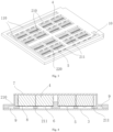
Fig. 1 is a schematic exploded structural drawing of the battery pack according to the present utility model. -
Fig. 2 is a schematic structural drawing of the battery case according to the present utility model, with the cooling plate and part of the battery module removed. -
Fig. 3 is a schematic structural drawing of the battery case according to the present utility model, with the bottom plate removed. -
Fig. 4 is a schematic sectional structural drawing of the battery case according to the present utility model. -
Fig. 5 is a schematic drawing showing the direction of gas flow during gas venting from the battery case according to the present utility model.
1 - housing; 110 - gas vent groove; 2 - support beam; 210 - transverse beam; 211 - gas vent hole; 220 - longitudinal beam; 3 - bottom plate; 4 - battery module; 5 - gas vent valve; 6 - pressure relief cavity; 7 - cooling plate; 8 - first fire protection layer; 9 - gas vent channel; 10 - filtering gas exit valve; 11 - hollow region. - The present utility model is described in further detail below with reference to the drawings and embodiments, to enable a person skilled in the art to implement the utility model based on the text herein.
- It should be understood that terms such as "having", "including" and "comprising" used herein do not rule out the presence or addition of one or more other elements or combinations thereof.
- As shown in
Figs. 1-5 , the present utility model provides a battery case and a battery pack, comprising: - a
housing 1, for accommodating abattery module 4; -
multiple support beams 2 arranged on a wall of thehousing 1, for contiguously supporting the accommodatedbattery module 4; - wherein a corresponding space region is formed between at least two
adjacent support beams 2 of themultiple support beams 2 when thebattery module 4 is contiguously supported, the space region forming apressure relief cavity 6 for agas vent valve 5 at the bottom of thebattery module 4 to vent gas into; - wherein a wall of the
housing 1 is the bottom of the battery case. - Operating principles of the technical solution described above: regarding the arrangement positions of the
multiple support beams 2 on thehousing 1, the present utility model is not limited to this, and they may be on any wall of thehousing 1; - the
multiple support beams 2 may be arranged as follows: themultiple support beams 2 are arranged in parallel or themultiple support beams 2 are arranged longitudinally and transversely in an intersecting fashion, with a region enclosed between at least twoadjacent support beams 2 forming ahollow region 11, and thepressure relief cavity 6 being formed by thehollow region 11, a bottom face of thehousing 1 and a bottom face of thebattery module 4; - a
bottom plate 3 is provided at the bottom of thehousing 1, thebottom plate 3 being configured as the bottom of the battery case, and thebottom plate 3 being fixed to the bottom of thehousing 1 by screw connection; there is a sealed connection between thebottom plate 3 and thesupport beam 2, so that thepressure relief cavity 6 formed is a sealed cavity; - the
battery module 4 is composed of multiple battery units, with agas vent valve 5 provided at the bottom of each battery unit; a partial region of the bottom of thebattery module 4 is fixed to thesupport beams 2 by adhesion, thesupport beams 2 providing weight support for thebattery module 4, and thegas vent valves 5 arranged at the bottom of thebattery module 4 correspond to thehollow regions 11; thus, the space regions formed by the bottom face of thebattery module 4, the bottom face of thehousing 1 and thehollow regions 11 arepressure relief cavities 6, and when one of the battery units vents gas through thegas vent valve 5 during thermal runaway, the gas is vented directly into thepressure relief cavity 6, and vented to the outside of thehousing 1 via thepressure relief cavity 6. - Beneficial effects of the technical solution described above: through the design of the structure above, the
multiple support beams 2 can provide weight support for thebattery module 4, without any need for the whole of the bottom face of thebattery module 4 to be adhered to the bottom plate; thus, ingenious use is made of the bottom face of thebattery module 4, thebottom plate 3 and thehollow region 11 to form thepressure relief cavity 6 which is isolated from a high-voltage connection chamber of the battery pack, so that high-temperature gas vented by a battery unit during thermal runaway is separated from the high-voltage connection chamber, thus avoiding a short circuit. Moreover, the gas vented by the battery unit during thermal runaway does not need to pass through a weak point, so the process of battery unit gas venting is smooth. Furthermore, this gas venting structure has the advantages of being low-cost with a simple structure, and being easy to manufacture. - In one embodiment, a
cooling plate 7 is provided at the top of thehousing 1; a side of thecooling plate 7 that is in contact with thebattery module 4 is provided with a non-adhesive thermally conductive layer. - Operating principles and beneficial effects of the technical solution described above: the
cooling plate 7 is arranged at the top of thebattery module 4 and fixed to the top of thehousing 1 by screw connection, which can avoid a situation where thecooling plate 7 bears the weight of thebattery module 4, thereby avoiding an increase in weight and structural complexity; moreover, gas vented by a battery unit during thermal runaway does not need to pass through thecooling plate 7 to enter thepressure relief cavity 6, so the cooling area is increased in comparison with common bottom-vented battery units and designs with bottom cooling;
the non-adhesive thermally conductive layer employs a non-adhesive thermally conductive glue or thermally conductive pad, to achieve a thermally conductive connection to thebattery module 4, without being fixed by adhesion to thebattery module 4, instead being detachably connected to the top of thehousing 1, thereby facilitating separate replacement of the cooling plate. - In an embodiment, a first
fire protection layer 8 is provided on the side of thebattery module 4 that faces towards thepressure relief cavity 6. - Operating principles and beneficial effects of the technical solution described above: the bottom of the
battery module 4 is a constituent part of thepressure relief cavity 6, so when a battery unit vents gas during thermal runaway, high-temperature gas or flames will contact the bottom of thebattery module 4; to better protect thebattery module 4, a fire-retardant, thermally isolating coating is applied to the bottom face thereof to form the firstfire protection layer 8, thus protecting battery units which have not experienced thermal runaway, and isolating the generated high-temperature gas or flames from the high-voltage connection chamber, thus making it possible to meet heat diffusion protection requirements while reducing the structural complexity. - In one embodiment, a region of the
battery module 4 in contact with thesupport beam 2 is connected by means of an adhesive layer. - Operating principles and beneficial effects of the technical solution described above: two opposite sides of the bottom face of the
battery module 4 are fixed to thesupport beams 2 by means of the adhesive layer, which is preferably structural glue; the use of this fixing method simplifies the installation structure of thehousing 1 and thebattery module 4. - In one embodiment, the
multiple support beams 2 comprise: multipletransverse beams 210 and multiplelongitudinal beams 220 arranged to intersect each other horizontally and perpendicularly;
two adjacent saidtransverse beams 210 form a corresponding space region when contiguously supporting thebattery module 4, and the multiplelongitudinal beams 220 divide the space region into multiple space units to formpressure relief cavities 6 forgas vent valves 5 at the bottom of thebattery module 4 to vent gas into. - Operating principles and beneficial effects of the technical solution described above: the multiple
transverse beams 210 and multiplelongitudinal beams 220 are arranged to intersect each other horizontally and perpendicularly, with two adjacenttransverse beams 210 and twolongitudinal beams 220 enclosing ahollow region 11 therebetween, eachhollow region 11 being able to accommodate multiplegas vent valves 5; two sides of the bottom face of thebattery module 4 are adhered to thetransverse beams 210, multiple battery units are arranged in the length direction of thetransverse beams 210, thegas vent valves 5 on the battery units are kept away from thelongitudinal beams 220, and partial regions of the battery units in contact with thelongitudinal beams 220 are also fixed by adhesion, providing effective support for thebattery module 4. - In one embodiment, a
gas vent hole 211 in communication with thepressure relief cavity 6 is provided on thetransverse beam 210, and agas vent channel 9 in communication with thegas vent hole 211 is provided inside a wall of thehousing 1;
a filteringgas exit valve 10 is provided on thehousing 1, one end of thegas vent channel 9 being in communication with the filteringgas exit valve 10, and a gas outlet of the filteringgas exit valve 10 facing towards the outside of thehousing 1. - Operating principles and beneficial effects of the technical solution described above: the bottom face of the housing 1 that is connected to the bottom plate 3 is provided with a gas vent groove 110 in communication with the gas vent hole 211, the gas vent channel 9 being formed between the gas vent groove 110 and the bottom plate 3; a top face and a bottom face of the transverse beam 210 are fixed to the battery module 4 and the bottom plate 3 respectively, the gas vent hole 211 is arranged on a side face of the transverse beam 210 located in the pressure relief cavity 6 in such a way as to run therethrough, communication is established between adjacent pressure relief cavities 6 by means of the gas vent hole 211, and the gas vent hole 211 on the outermost transverse beam 210 is in communication with the gas vent groove 110; when a battery unit vents gas during thermal runaway, high-temperature gas will first be vented into the pressure relief cavity 6, then enter the closest gas vent channel 9 in communication with the pressure relief cavity 6, and finally be vented to the outside of the housing 1 by the filtering gas exit valve 10; the filtering gas exit valve 10 can filter the flames produced during runaway of the battery unit, so that flames are not vented to the outside of the housing 1, causing serious harm.
- In one embodiment, a partition plate is provided in the
housing 1, being located at one side of thebattery module 4; and the filteringgas exit valve 10 is provided at the side of the partition plate which is remote from thebattery module 4. - Operating principles and beneficial effects of the technical solution described above: the partition plate separates the filtering
gas exit valve 10 and thebattery module 4 located in thehousing 1, while the high-voltage connection chamber of the battery pack is formed by one side of the partition plate, thehousing 1 and thebottom plate 3, said side being the side which is remote from thebattery module 4; and thebottom plate 3 seals the bottom face of thehousing 1 and all of thepressure relief cavities 6, so high-temperature gas or flames produced by a battery unit during runaway will not enter the high-voltage connection chamber, thus achieving effective isolation. - In one embodiment, the
gas vent channel 9 is arranged around the outside of the multiplepressure relief cavities 6. - Operating principles and beneficial effects of the technical solution described above: the
gas vent channel 9 is arranged around the outside of the two outermosttransverse beams 210 in a continuous fashion, high-temperature gas or flames in all of thepressure relief cavities 6 is vented into thegas vent channel 9 through the gas vent holes 211 in the outermost twotransverse beams 210, and finally vented to the outside of thehousing 1 through the filteringgas exit valve 10 from one end of thegas vent channel 9, thus achieving efficient venting of gas. - In one embodiment, a second fire protection layer is provided on a wall of the
housing 1 which is opposite thegas vent valve 5. - Operating principles and beneficial effects of the technical solution described above: a wall of the
housing 1 in this embodiment is thebottom plate 3, and thebottom plate 3 participates in the sealing of the entire battery pack, i.e. thebottom plate 3 is in sealed connection with the bottom face of thehousing 1, the bottom face of thetransverse beam 210, a bottom face of thelongitudinal beam 220 and a bottom face of the partition plate; to ensure that thebottom plate 3 is not penetrated during thermal runaway of a battery unit, the second fire protection layer is arranged at the side of thebottom plate 3 which is opposite thegas vent valve 5, to provide fire protection and thermal isolation. - The present utility model also provides a battery pack, comprising the battery case according to any one of the embodiments above.
- Operating principles and beneficial effects of the technical solution described above: the battery pack comprises: a
housing 1, abottom plate 3, abattery module 4 and acooling plate 7; a battery unit installation zone for installing thebattery module 4, and a high-voltage connection chamber for pole post electrical connections of thebattery module 4, are provided in thehousing 1. - Bottom venting of gas from the
battery module 4 generally necessitates complex protection measures and structure in the design of the battery pack as a whole, whereas the battery pack in the present utility model employs a design in which pole posts for positive and negative poles are arranged at the side and gas is vented from the bottom of thebattery module 4, and also employs the battery case described above, thus simplifying the installation structure of thebattery module 4 and thehousing 1, achieving effective protection in the event of runaway of a battery unit in the battery pack, and meeting the demand to make the battery pack as a whole lightweight. The overall design is simple and easy to implement. - In the description of the present utility model, it must be understood that the orientational or positional relationships indicated by terms such as "centre", "longitudinal", "transverse", "length", "width", "thickness", "up", "down", "front", "rear", "left", "right", "vertical", "horizontal", "top", "bottom", "inner", "outer", "clockwise", "anticlockwise", "axial", "radial", "circumferential", etc. are based on the orientational or positional relationships shown in the drawings, and merely intended to facilitate and simplify description of the present utility model, rather than indicating or implying that the apparatus or element referred to must have a specific orientation or be constructed and operated in a specific orientation, and therefore must not be construed as limiting the present utility model.
- In the present utility model, unless otherwise explicitly specified and defined, terms such as "installed", "connected together", "connected", "fixed", etc. should be understood in a broad sense, e.g. may mean fixedly connected, detachably connected or forming a single piece; mechanically connected, electrically connected or capable of communicating with each other; directly connected together, or indirectly connected together via an intermediate medium; internal communication between two elements, or an interactive relationship between two elements, unless otherwise explicitly defined. To a person skilled in the art, the specific meanings of the abovementioned terms in the present utility model may be understood according to the particular circumstances.
- Although embodiments of the present utility model have been disclosed above, it is not limited to the applications listed in this Description and the embodiments, and is absolutely applicable to all kinds of fields suitable for the present utility model. To those familiar with this field, other alterations may be easily implemented. Thus, without deviating from the general concept defined by the claims and their equivalent scope, the present utility model is not limited to specific details and the example drawings shown and described herein.
Claims (10)
- Battery case, characterized by comprising:a housing (1), for accommodating a battery module (4);multiple support beams (2) arranged on a wall of the housing (1), for contiguously supporting the accommodated battery module (4);wherein a corresponding space region is formed between at least two adjacent support beams (2) of the multiple support beams (2) when the battery module (4) is contiguously supported, the space region forming a pressure relief cavity (6) for a gas vent valve (5) at the bottom of the battery module (4) to vent gas into.
- Battery case according to Claim 1, wherein a wall of the housing (1) is the bottom of the battery case.
- Battery case according to Claim 1, characterized in that a cooling plate (7) is provided at the top of the housing (1), and a side of the cooling plate (7) that is in contact with the battery module (4) is provided with a non-adhesive thermally conductive layer.
- Battery case according to Claim 1, characterized in that the side of the battery module (4) that faces towards the pressure relief cavity (6) is provided with a first fire protection layer (8).
- Battery case according to Claim 1, characterized in that a region of the battery module (4) in contact with the support beam (2) is connected by means of an adhesive layer.
- Battery case according to Claim 1, characterized in that the multiple support beams (2) comprise: multiple transverse beams (210) and multiple longitudinal beams (220) arranged to intersect each other horizontally and perpendicularly;
two adjacent said transverse beams (210) form a corresponding space region when contiguously supporting the battery module (4), and the multiple longitudinal beams (220) divide the space region into multiple space units to form pressure relief cavities (6) for gas vent valves (5) at the bottom of the battery module (4) to vent gas into. - Battery case according to Claim 6, characterized in that gas vent holes (211) in communication with the pressure relief cavities (6) are provided on the transverse beams (210), and a gas vent channel (9) in communication with the gas vent holes (211) is provided inside a wall of the housing (1);
a filtering gas exit valve (10) is provided on the housing (1), one end of the gas vent channel (9) being in communication with the filtering gas exit valve (10), and a gas outlet of the filtering gas exit valve (10) facing towards the outside of the housing (1). - Battery case according to Claim 7, characterized in that the gas vent channel (9) is arranged around the outside of the multiple pressure relief cavities (6).
- Battery case according to Claim 1, characterized in that a second fire protection layer is provided on a wall of the housing (1) which is opposite the gas vent valve (5).
- Battery pack, characterized by comprising the battery case according to any one of Claims 1 -9.
Applications Claiming Priority (1)
| Application Number | Priority Date | Filing Date | Title |
|---|---|---|---|
| CN202221516826.XU CN217544813U (en) | 2022-06-16 | 2022-06-16 | Battery box and battery package |
Publications (1)
| Publication Number | Publication Date |
|---|---|
| EP4293804A1 true EP4293804A1 (en) | 2023-12-20 |
Family
ID=83419133
Family Applications (1)
| Application Number | Title | Priority Date | Filing Date |
|---|---|---|---|
| EP23177654.3A Withdrawn EP4293804A1 (en) | 2022-06-16 | 2023-06-06 | Battery box and battery module |
Country Status (2)
| Country | Link |
|---|---|
| EP (1) | EP4293804A1 (en) |
| CN (1) | CN217544813U (en) |
Cited By (1)
| Publication number | Priority date | Publication date | Assignee | Title |
|---|---|---|---|---|
| CN118693406A (en) * | 2024-07-12 | 2024-09-24 | 宜宾纵贯线科技股份有限公司 | A double-sided cooling plate and energy storage system formed by stamping |
Families Citing this family (9)
| Publication number | Priority date | Publication date | Assignee | Title |
|---|---|---|---|---|
| CN217507557U (en) * | 2022-06-30 | 2022-09-27 | 宁德时代新能源科技股份有限公司 | Box, battery and electrical equipment |
| CN115295946B (en) * | 2022-08-16 | 2024-07-16 | 小米汽车科技有限公司 | Battery Pack and Thermal Runaway Protection Design Method |
| CN116544604A (en) * | 2023-04-13 | 2023-08-04 | 惠州亿纬动力电池有限公司 | Battery pack |
| CN219917482U (en) * | 2023-04-13 | 2023-10-27 | 惠州亿纬锂能股份有限公司 | Battery assembly |
| WO2024213041A1 (en) * | 2023-04-13 | 2024-10-17 | 惠州亿纬动力电池有限公司 | Battery pack |
| EP4738589A1 (en) * | 2023-06-28 | 2026-05-06 | SVOLT Energy Technology Co., Ltd. | Battery pack |
| CN222838941U (en) * | 2024-04-23 | 2025-05-06 | 宁德时代新能源科技股份有限公司 | Battery and electricity utilization device |
| CN119674400B (en) * | 2024-12-17 | 2026-01-13 | 蜂巢能源科技股份有限公司 | Battery pack housing and battery pack |
| CN120165140B (en) * | 2025-05-19 | 2025-09-23 | 宁德时代新能源科技股份有限公司 | Battery devices and electrical equipment |
Citations (5)
| Publication number | Priority date | Publication date | Assignee | Title |
|---|---|---|---|---|
| CA3021577A1 (en) * | 2016-04-20 | 2017-10-26 | Corvus Energy Inc. | Method and apparatus for managing thermal runaway gases in a battery system |
| CN213212323U (en) * | 2020-09-28 | 2021-05-14 | 福州游标卡尺网络科技有限公司 | Heat dissipation and heat insulation protection box of lithium battery |
| CN113273024A (en) * | 2018-11-13 | 2021-08-17 | 瑞维安知识产权控股有限责任公司 | Battery cell stack thermal runaway mitigation |
| EP3910699A1 (en) * | 2020-05-12 | 2021-11-17 | Samsung SDI Co., Ltd. | Battery system and vehicle including the battery system |
| US11296381B2 (en) * | 2016-07-29 | 2022-04-05 | Apple Inc. | High-density battery pack |
-
2022
- 2022-06-16 CN CN202221516826.XU patent/CN217544813U/en active Active
-
2023
- 2023-06-06 EP EP23177654.3A patent/EP4293804A1/en not_active Withdrawn
Patent Citations (5)
| Publication number | Priority date | Publication date | Assignee | Title |
|---|---|---|---|---|
| CA3021577A1 (en) * | 2016-04-20 | 2017-10-26 | Corvus Energy Inc. | Method and apparatus for managing thermal runaway gases in a battery system |
| US11296381B2 (en) * | 2016-07-29 | 2022-04-05 | Apple Inc. | High-density battery pack |
| CN113273024A (en) * | 2018-11-13 | 2021-08-17 | 瑞维安知识产权控股有限责任公司 | Battery cell stack thermal runaway mitigation |
| EP3910699A1 (en) * | 2020-05-12 | 2021-11-17 | Samsung SDI Co., Ltd. | Battery system and vehicle including the battery system |
| CN213212323U (en) * | 2020-09-28 | 2021-05-14 | 福州游标卡尺网络科技有限公司 | Heat dissipation and heat insulation protection box of lithium battery |
Cited By (1)
| Publication number | Priority date | Publication date | Assignee | Title |
|---|---|---|---|---|
| CN118693406A (en) * | 2024-07-12 | 2024-09-24 | 宜宾纵贯线科技股份有限公司 | A double-sided cooling plate and energy storage system formed by stamping |
Also Published As
| Publication number | Publication date |
|---|---|
| CN217544813U (en) | 2022-10-04 |
Similar Documents
| Publication | Publication Date | Title |
|---|---|---|
| CN217544813U (en) | Battery box and battery package | |
| US20220294048A1 (en) | Traction battery pack with heat-insulating assembly | |
| CN216529223U (en) | a battery pack | |
| WO2023273886A1 (en) | Battery pack lower case, battery pack, and vehicle | |
| WO2023273885A1 (en) | Battery pack lower case body, battery pack and vehicle | |
| CN116706385A (en) | A double-layer module and battery pack | |
| CN117080667A (en) | Battery box and battery pack | |
| CN218039525U (en) | Battery module and power battery | |
| CN219917482U (en) | Battery assembly | |
| CN216354512U (en) | Battery Modules and Battery Packs | |
| CN218039573U (en) | A battery pack and vehicle | |
| CN116093517A (en) | A battery pack and vehicle | |
| CN213340635U (en) | Battery cell module and battery pack | |
| CN115000484A (en) | Fuel cell stack structure | |
| CN220138558U (en) | Battery pack box and battery pack | |
| CN220585352U (en) | High-capacity battery | |
| CN117477063A (en) | High-capacity battery and single battery | |
| CN113036276A (en) | Battery pack and electric vehicle | |
| CN217562756U (en) | Battery cell unit and assembly | |
| CN220544156U (en) | Explosion-proof structure of battery and battery package | |
| CN219873670U (en) | High-capacity battery and single battery | |
| JP7804166B2 (en) | Modular Energy Storage Battery | |
| CN218731518U (en) | Battery pack and vehicle | |
| CN218887446U (en) | Battery pack and power device | |
| CN218602673U (en) | A division board for battery module and battery module thereof |
Legal Events
| Date | Code | Title | Description |
|---|---|---|---|
| PUAI | Public reference made under article 153(3) epc to a published international application that has entered the european phase |
Free format text: ORIGINAL CODE: 0009012 |
|
| STAA | Information on the status of an ep patent application or granted ep patent |
Free format text: STATUS: THE APPLICATION HAS BEEN PUBLISHED |
|
| AK | Designated contracting states |
Kind code of ref document: A1 Designated state(s): AL AT BE BG CH CY CZ DE DK EE ES FI FR GB GR HR HU IE IS IT LI LT LU LV MC ME MK MT NL NO PL PT RO RS SE SI SK SM TR |
|
| STAA | Information on the status of an ep patent application or granted ep patent |
Free format text: STATUS: THE APPLICATION IS DEEMED TO BE WITHDRAWN |
|
| 18D | Application deemed to be withdrawn |
Effective date: 20240621 |