EP4293796A1 - Protective circuit for sensing vibration of fuse box - Google Patents
Protective circuit for sensing vibration of fuse box Download PDFInfo
- Publication number
- EP4293796A1 EP4293796A1 EP22771684.2A EP22771684A EP4293796A1 EP 4293796 A1 EP4293796 A1 EP 4293796A1 EP 22771684 A EP22771684 A EP 22771684A EP 4293796 A1 EP4293796 A1 EP 4293796A1
- Authority
- EP
- European Patent Office
- Prior art keywords
- fuse
- battery
- bus bar
- battery pack
- terminal
- Prior art date
- Legal status (The legal status is an assumption and is not a legal conclusion. Google has not performed a legal analysis and makes no representation as to the accuracy of the status listed.)
- Pending
Links
Images

Classifications
-
- G—PHYSICS
- G01—MEASURING; TESTING
- G01H—MEASUREMENT OF MECHANICAL VIBRATIONS OR ULTRASONIC, SONIC OR INFRASONIC WAVES
- G01H1/00—Measuring characteristics of vibrations in solids by using direct conduction to the detector
-
- H—ELECTRICITY
- H01—ELECTRIC ELEMENTS
- H01M—PROCESSES OR MEANS, e.g. BATTERIES, FOR THE DIRECT CONVERSION OF CHEMICAL ENERGY INTO ELECTRICAL ENERGY
- H01M10/00—Secondary cells; Manufacture thereof
- H01M10/42—Methods or arrangements for servicing or maintenance of secondary cells or secondary half-cells
- H01M10/48—Accumulators combined with arrangements for measuring, testing or indicating the condition of cells, e.g. the level or density of the electrolyte
-
- G—PHYSICS
- G01—MEASURING; TESTING
- G01H—MEASUREMENT OF MECHANICAL VIBRATIONS OR ULTRASONIC, SONIC OR INFRASONIC WAVES
- G01H11/00—Measuring mechanical vibrations or ultrasonic, sonic or infrasonic waves by detecting changes in electric or magnetic properties
- G01H11/06—Measuring mechanical vibrations or ultrasonic, sonic or infrasonic waves by detecting changes in electric or magnetic properties by electric means
-
- G—PHYSICS
- G01—MEASURING; TESTING
- G01R—MEASURING ELECTRIC VARIABLES; MEASURING MAGNETIC VARIABLES
- G01R19/00—Arrangements for measuring currents or voltages or for indicating presence or sign thereof
- G01R19/165—Indicating that current or voltage is either above or below a predetermined value or within or outside a predetermined range of values
-
- G—PHYSICS
- G01—MEASURING; TESTING
- G01R—MEASURING ELECTRIC VARIABLES; MEASURING MAGNETIC VARIABLES
- G01R19/00—Arrangements for measuring currents or voltages or for indicating presence or sign thereof
- G01R19/165—Indicating that current or voltage is either above or below a predetermined value or within or outside a predetermined range of values
- G01R19/16566—Circuits and arrangements for comparing voltage or current with one or several thresholds and for indicating the result not covered by subgroups G01R19/16504, G01R19/16528, G01R19/16533
-
- H—ELECTRICITY
- H01—ELECTRIC ELEMENTS
- H01H—ELECTRIC SWITCHES; RELAYS; SELECTORS; EMERGENCY PROTECTIVE DEVICES
- H01H85/00—Protective devices in which the current flows through a part of fusible material and this current is interrupted by displacement of the fusible material when this current becomes excessive
- H01H85/02—Details
- H01H85/04—Fuses, i.e. expendable parts of the protective device, e.g. cartridges
- H01H85/05—Component parts thereof
- H01H85/143—Electrical contacts; Fastening fusible members to such contacts
-
- H—ELECTRICITY
- H01—ELECTRIC ELEMENTS
- H01H—ELECTRIC SWITCHES; RELAYS; SELECTORS; EMERGENCY PROTECTIVE DEVICES
- H01H85/00—Protective devices in which the current flows through a part of fusible material and this current is interrupted by displacement of the fusible material when this current becomes excessive
- H01H85/02—Details
- H01H85/04—Fuses, i.e. expendable parts of the protective device, e.g. cartridges
- H01H85/05—Component parts thereof
- H01H85/165—Casings
-
- H—ELECTRICITY
- H01—ELECTRIC ELEMENTS
- H01M—PROCESSES OR MEANS, e.g. BATTERIES, FOR THE DIRECT CONVERSION OF CHEMICAL ENERGY INTO ELECTRICAL ENERGY
- H01M10/00—Secondary cells; Manufacture thereof
- H01M10/42—Methods or arrangements for servicing or maintenance of secondary cells or secondary half-cells
-
- H—ELECTRICITY
- H01—ELECTRIC ELEMENTS
- H01M—PROCESSES OR MEANS, e.g. BATTERIES, FOR THE DIRECT CONVERSION OF CHEMICAL ENERGY INTO ELECTRICAL ENERGY
- H01M10/00—Secondary cells; Manufacture thereof
- H01M10/42—Methods or arrangements for servicing or maintenance of secondary cells or secondary half-cells
- H01M10/425—Structural combination with electronic components, e.g. electronic circuits integrated to the outside of the casing
-
- H—ELECTRICITY
- H01—ELECTRIC ELEMENTS
- H01M—PROCESSES OR MEANS, e.g. BATTERIES, FOR THE DIRECT CONVERSION OF CHEMICAL ENERGY INTO ELECTRICAL ENERGY
- H01M10/00—Secondary cells; Manufacture thereof
- H01M10/42—Methods or arrangements for servicing or maintenance of secondary cells or secondary half-cells
- H01M10/48—Accumulators combined with arrangements for measuring, testing or indicating the condition of cells, e.g. the level or density of the electrolyte
- H01M10/482—Accumulators combined with arrangements for measuring, testing or indicating the condition of cells, e.g. the level or density of the electrolyte for several batteries or cells simultaneously or sequentially
-
- H—ELECTRICITY
- H01—ELECTRIC ELEMENTS
- H01M—PROCESSES OR MEANS, e.g. BATTERIES, FOR THE DIRECT CONVERSION OF CHEMICAL ENERGY INTO ELECTRICAL ENERGY
- H01M50/00—Constructional details or processes of manufacture of the non-active parts of electrochemical cells other than fuel cells, e.g. hybrid cells
- H01M50/20—Mountings; Secondary casings or frames; Racks, modules or packs; Suspension devices; Shock absorbers; Transport or carrying devices; Holders
- H01M50/204—Racks, modules or packs for multiple batteries or multiple cells
-
- H—ELECTRICITY
- H01—ELECTRIC ELEMENTS
- H01M—PROCESSES OR MEANS, e.g. BATTERIES, FOR THE DIRECT CONVERSION OF CHEMICAL ENERGY INTO ELECTRICAL ENERGY
- H01M50/00—Constructional details or processes of manufacture of the non-active parts of electrochemical cells other than fuel cells, e.g. hybrid cells
- H01M50/20—Mountings; Secondary casings or frames; Racks, modules or packs; Suspension devices; Shock absorbers; Transport or carrying devices; Holders
- H01M50/204—Racks, modules or packs for multiple batteries or multiple cells
- H01M50/207—Racks, modules or packs for multiple batteries or multiple cells characterised by their shape
- H01M50/209—Racks, modules or packs for multiple batteries or multiple cells characterised by their shape adapted for prismatic or rectangular cells
-
- H—ELECTRICITY
- H01—ELECTRIC ELEMENTS
- H01M—PROCESSES OR MEANS, e.g. BATTERIES, FOR THE DIRECT CONVERSION OF CHEMICAL ENERGY INTO ELECTRICAL ENERGY
- H01M50/00—Constructional details or processes of manufacture of the non-active parts of electrochemical cells other than fuel cells, e.g. hybrid cells
- H01M50/20—Mountings; Secondary casings or frames; Racks, modules or packs; Suspension devices; Shock absorbers; Transport or carrying devices; Holders
- H01M50/204—Racks, modules or packs for multiple batteries or multiple cells
- H01M50/207—Racks, modules or packs for multiple batteries or multiple cells characterised by their shape
- H01M50/211—Racks, modules or packs for multiple batteries or multiple cells characterised by their shape adapted for pouch cells
-
- H—ELECTRICITY
- H01—ELECTRIC ELEMENTS
- H01M—PROCESSES OR MEANS, e.g. BATTERIES, FOR THE DIRECT CONVERSION OF CHEMICAL ENERGY INTO ELECTRICAL ENERGY
- H01M50/00—Constructional details or processes of manufacture of the non-active parts of electrochemical cells other than fuel cells, e.g. hybrid cells
- H01M50/20—Mountings; Secondary casings or frames; Racks, modules or packs; Suspension devices; Shock absorbers; Transport or carrying devices; Holders
- H01M50/233—Mountings; Secondary casings or frames; Racks, modules or packs; Suspension devices; Shock absorbers; Transport or carrying devices; Holders characterised by physical properties of casings or racks, e.g. dimensions
- H01M50/242—Mountings; Secondary casings or frames; Racks, modules or packs; Suspension devices; Shock absorbers; Transport or carrying devices; Holders characterised by physical properties of casings or racks, e.g. dimensions adapted for protecting batteries against vibrations, collision impact or swelling
-
- H—ELECTRICITY
- H01—ELECTRIC ELEMENTS
- H01M—PROCESSES OR MEANS, e.g. BATTERIES, FOR THE DIRECT CONVERSION OF CHEMICAL ENERGY INTO ELECTRICAL ENERGY
- H01M50/00—Constructional details or processes of manufacture of the non-active parts of electrochemical cells other than fuel cells, e.g. hybrid cells
- H01M50/20—Mountings; Secondary casings or frames; Racks, modules or packs; Suspension devices; Shock absorbers; Transport or carrying devices; Holders
- H01M50/284—Mountings; Secondary casings or frames; Racks, modules or packs; Suspension devices; Shock absorbers; Transport or carrying devices; Holders with incorporated circuit boards, e.g. printed circuit boards [PCB]
-
- H—ELECTRICITY
- H01—ELECTRIC ELEMENTS
- H01M—PROCESSES OR MEANS, e.g. BATTERIES, FOR THE DIRECT CONVERSION OF CHEMICAL ENERGY INTO ELECTRICAL ENERGY
- H01M50/00—Constructional details or processes of manufacture of the non-active parts of electrochemical cells other than fuel cells, e.g. hybrid cells
- H01M50/20—Mountings; Secondary casings or frames; Racks, modules or packs; Suspension devices; Shock absorbers; Transport or carrying devices; Holders
- H01M50/296—Mountings; Secondary casings or frames; Racks, modules or packs; Suspension devices; Shock absorbers; Transport or carrying devices; Holders characterised by terminals of battery packs
-
- H—ELECTRICITY
- H01—ELECTRIC ELEMENTS
- H01M—PROCESSES OR MEANS, e.g. BATTERIES, FOR THE DIRECT CONVERSION OF CHEMICAL ENERGY INTO ELECTRICAL ENERGY
- H01M50/00—Constructional details or processes of manufacture of the non-active parts of electrochemical cells other than fuel cells, e.g. hybrid cells
- H01M50/50—Current conducting connections for cells or batteries
- H01M50/502—Interconnectors for connecting terminals of adjacent batteries; Interconnectors for connecting cells outside a battery casing
- H01M50/505—Interconnectors for connecting terminals of adjacent batteries; Interconnectors for connecting cells outside a battery casing comprising a single busbar
-
- H—ELECTRICITY
- H01—ELECTRIC ELEMENTS
- H01M—PROCESSES OR MEANS, e.g. BATTERIES, FOR THE DIRECT CONVERSION OF CHEMICAL ENERGY INTO ELECTRICAL ENERGY
- H01M50/00—Constructional details or processes of manufacture of the non-active parts of electrochemical cells other than fuel cells, e.g. hybrid cells
- H01M50/50—Current conducting connections for cells or batteries
- H01M50/502—Interconnectors for connecting terminals of adjacent batteries; Interconnectors for connecting cells outside a battery casing
- H01M50/519—Interconnectors for connecting terminals of adjacent batteries; Interconnectors for connecting cells outside a battery casing comprising printed circuit boards [PCB]
-
- H—ELECTRICITY
- H01—ELECTRIC ELEMENTS
- H01M—PROCESSES OR MEANS, e.g. BATTERIES, FOR THE DIRECT CONVERSION OF CHEMICAL ENERGY INTO ELECTRICAL ENERGY
- H01M50/00—Constructional details or processes of manufacture of the non-active parts of electrochemical cells other than fuel cells, e.g. hybrid cells
- H01M50/50—Current conducting connections for cells or batteries
- H01M50/569—Constructional details of current conducting connections for detecting conditions inside cells or batteries, e.g. details of voltage sensing terminals
-
- H—ELECTRICITY
- H01—ELECTRIC ELEMENTS
- H01M—PROCESSES OR MEANS, e.g. BATTERIES, FOR THE DIRECT CONVERSION OF CHEMICAL ENERGY INTO ELECTRICAL ENERGY
- H01M50/00—Constructional details or processes of manufacture of the non-active parts of electrochemical cells other than fuel cells, e.g. hybrid cells
- H01M50/50—Current conducting connections for cells or batteries
- H01M50/572—Means for preventing undesired use or discharge
- H01M50/574—Devices or arrangements for the interruption of current
- H01M50/583—Devices or arrangements for the interruption of current in response to current, e.g. fuses
-
- G—PHYSICS
- G01—MEASURING; TESTING
- G01R—MEASURING ELECTRIC VARIABLES; MEASURING MAGNETIC VARIABLES
- G01R31/00—Arrangements for testing electric properties; Arrangements for locating electric faults; Arrangements for electrical testing characterised by what is being tested not provided for elsewhere
- G01R31/36—Arrangements for testing, measuring or monitoring the electrical condition of accumulators or electric batteries, e.g. capacity or state of charge [SoC]
- G01R31/392—Determining battery ageing or deterioration, e.g. state of health
-
- G—PHYSICS
- G01—MEASURING; TESTING
- G01R—MEASURING ELECTRIC VARIABLES; MEASURING MAGNETIC VARIABLES
- G01R31/00—Arrangements for testing electric properties; Arrangements for locating electric faults; Arrangements for electrical testing characterised by what is being tested not provided for elsewhere
- G01R31/50—Testing of electric apparatus, lines, cables or components for short-circuits, continuity, leakage current or incorrect line connections
- G01R31/54—Testing for continuity
-
- H—ELECTRICITY
- H01—ELECTRIC ELEMENTS
- H01H—ELECTRIC SWITCHES; RELAYS; SELECTORS; EMERGENCY PROTECTIVE DEVICES
- H01H85/00—Protective devices in which the current flows through a part of fusible material and this current is interrupted by displacement of the fusible material when this current becomes excessive
- H01H85/02—Details
- H01H85/20—Bases for supporting the fuse; Separate parts thereof
- H01H2085/2075—Junction box, having holders integrated with several other holders in a particular wiring layout
- H01H2085/208—Junction box, having holders integrated with several other holders in a particular wiring layout specially adapted for vehicles
-
- H—ELECTRICITY
- H01—ELECTRIC ELEMENTS
- H01M—PROCESSES OR MEANS, e.g. BATTERIES, FOR THE DIRECT CONVERSION OF CHEMICAL ENERGY INTO ELECTRICAL ENERGY
- H01M10/00—Secondary cells; Manufacture thereof
- H01M10/42—Methods or arrangements for servicing or maintenance of secondary cells or secondary half-cells
- H01M10/425—Structural combination with electronic components, e.g. electronic circuits integrated to the outside of the casing
- H01M2010/4271—Battery management systems including electronic circuits, e.g. control of current or voltage to keep battery in healthy state, cell balancing
-
- H—ELECTRICITY
- H01—ELECTRIC ELEMENTS
- H01M—PROCESSES OR MEANS, e.g. BATTERIES, FOR THE DIRECT CONVERSION OF CHEMICAL ENERGY INTO ELECTRICAL ENERGY
- H01M2200/00—Safety devices for primary or secondary batteries
- H01M2200/10—Temperature sensitive devices
- H01M2200/103—Fuse
-
- H—ELECTRICITY
- H01—ELECTRIC ELEMENTS
- H01M—PROCESSES OR MEANS, e.g. BATTERIES, FOR THE DIRECT CONVERSION OF CHEMICAL ENERGY INTO ELECTRICAL ENERGY
- H01M2220/00—Batteries for particular applications
- H01M2220/20—Batteries in motive systems, e.g. vehicle, ship, plane
-
- H—ELECTRICITY
- H01—ELECTRIC ELEMENTS
- H01M—PROCESSES OR MEANS, e.g. BATTERIES, FOR THE DIRECT CONVERSION OF CHEMICAL ENERGY INTO ELECTRICAL ENERGY
- H01M50/00—Constructional details or processes of manufacture of the non-active parts of electrochemical cells other than fuel cells, e.g. hybrid cells
- H01M50/20—Mountings; Secondary casings or frames; Racks, modules or packs; Suspension devices; Shock absorbers; Transport or carrying devices; Holders
- H01M50/258—Modular batteries; Casings provided with means for assembling
-
- Y—GENERAL TAGGING OF NEW TECHNOLOGICAL DEVELOPMENTS; GENERAL TAGGING OF CROSS-SECTIONAL TECHNOLOGIES SPANNING OVER SEVERAL SECTIONS OF THE IPC; TECHNICAL SUBJECTS COVERED BY FORMER USPC CROSS-REFERENCE ART COLLECTIONS [XRACs] AND DIGESTS
- Y02—TECHNOLOGIES OR APPLICATIONS FOR MITIGATION OR ADAPTATION AGAINST CLIMATE CHANGE
- Y02E—REDUCTION OF GREENHOUSE GAS [GHG] EMISSIONS, RELATED TO ENERGY GENERATION, TRANSMISSION OR DISTRIBUTION
- Y02E60/00—Enabling technologies; Technologies with a potential or indirect contribution to GHG emissions mitigation
- Y02E60/10—Energy storage using batteries
-
- Y—GENERAL TAGGING OF NEW TECHNOLOGICAL DEVELOPMENTS; GENERAL TAGGING OF CROSS-SECTIONAL TECHNOLOGIES SPANNING OVER SEVERAL SECTIONS OF THE IPC; TECHNICAL SUBJECTS COVERED BY FORMER USPC CROSS-REFERENCE ART COLLECTIONS [XRACs] AND DIGESTS
- Y02—TECHNOLOGIES OR APPLICATIONS FOR MITIGATION OR ADAPTATION AGAINST CLIMATE CHANGE
- Y02T—CLIMATE CHANGE MITIGATION TECHNOLOGIES RELATED TO TRANSPORTATION
- Y02T10/00—Road transport of goods or passengers
- Y02T10/60—Other road transportation technologies with climate change mitigation effect
- Y02T10/70—Energy storage systems for electromobility, e.g. batteries
Definitions
- the present invention relates to a battery pack for a vehicle for detecting vibration flowing into a fuse box and a bus bar of the battery pack, and more particularly, to a battery pack including a vibration detection element that detects vibration flowing into the fuse box and the bus bar from the outside.
- the battery of this electric vehicle may be configured in various battery modules by connecting a number of battery cells in series with/parallel to each other according to a required power voltage and charge/discharge capacity.
- a battery pack structure is configured by adding a configuration such as a protection circuit to the battery module including at least one battery cell.
- a fuse used in the electric vehicle is melt and broken when an overcurrent flows in the battery module or pack circuit to block the circuit, thereby protecting the battery cell from ignition and damage.
- a plurality of fuses formed to be connected to the battery module and pack installed in the vehicle are aggregated so that the fuses may be coupled to and separated from each other in the fuse box.
- the present invention provides a means for detecting vibration in a fuse box which is vulnerable to vibration in a battery pack and to which the vibration applied to the battery pack is delivered well in order to effectively detect the vibration applied to the battery pack.
- the present invention is intended to provide a battery pack capable of increasing user stability from damage to the fuse box vulnerable to vibration and breakage caused by disconnection with the bus bar by detecting vibration applied to the fuse box of the electric vehicle through a vibration detection element.
- a battery pack comprises one or more battery modules provided with a plurality of battery cells, a bus bar connected to a module terminal of the battery module to electrically connect the one or more battery modules, and connected to an external BMS of the battery pack, and a fuse box in which a fuse connecting each of the battery modules and the bus bar is accommodated, a vibration detection element attached to one surface of the fuse box or one surface of the bus bar connected to the external BMS of the battery pack to detect vibration flowing into the fuse connected to each of the battery modules, and a BMS that includes the BMIC and is connected to the vibration detection element to perform a protection operation according to detected vibration of the battery module, and the vibration detection element is characterized in that it is directly connected to a BMIC through terminals at both ends thereof.
- the vibration detection element is characterized in that it is attached to the bus bar and fuse box in a form of a tape or a form of a FPCB transferred on a flexible substrate to sensitively sense the inflow of vibration, and is not damaged even by a temporary impact.
- the fuse box and the bus bar are characterized in that cumulative damage is generated therein due to vibration flows into from the outside.
- the vibration detection element is characterized in that it measures a change in voltage value according to vibration detection of the bus bar and the fuse box and delivers it to the BMS, and the BMS is characterized in that it compares the voltage value with a predetermined reference level, and performs a protection operation and transmits an alarm to a user when a maximum allowable level at the predetermined reference level is exceeded.
- a battery pack is configured to include a battery module, a bus bar electrically connecting the battery module, and a fuse box in which a fuse is accommodated, and include a vibration detection element attached to one surface of the fuse box or one surface of the bus bar.
- the fuse box or bus bar is a site where accumulated damage due to vibration flowing into from the outside of the battery pack is greatly generated, and the vibration detection element is attached thereto so that the vibration may be sensitively detected.
- the vibration detection element detects vibration flown into through the fuse box and the bus bar and transmits a change in voltage value according to the detected vibration to the BMS connected to both ends of the vibration detection element.
- the BMS may prevent loss of an overcurrent blocking function, such as the phenomenon of insensitivity of the fuse box due to vibration flowing into from the outside of the battery pack in advance.
- the present invention is configured with a battery pack 10 including a battery module 100, a fuse box 200, which includes a fuse 210, a fuse case 220 (see Figure 5 ), and a vibration detection element 230 (see Figure 4 or 5 ), and a bus bar 300, and a battery management system (BMS) 400 (see Figure 2 ) that controls the battery pack 10.
- a battery pack 10 including a battery module 100, a fuse box 200, which includes a fuse 210, a fuse case 220 (see Figure 5 ), and a vibration detection element 230 (see Figure 4 or 5 ), and a bus bar 300, and a battery management system (BMS) 400 (see Figure 2 ) that controls the battery pack 10.
- BMS battery management system
- the battery module 100 is configured by connecting a plurality of battery cells in series with or in parallel to each other, and at least one of these battery modules 100 is connected to configure the battery pack 10.
- the plurality of battery cells may be configured as cylindrical, pouch, and prismatic battery cells.
- the type of the battery cell may include, but is not limited to, a lithium ion battery, a lithium polymer battery, a nickel cadmium battery, and a nickel hydride battery.
- FIG. 4 illustrates a configuration of the fuse box 200 of the present invention.
- the fuse box 200 is configured with a fuse 210, a fuse case in which the fuse 210 is accommodated, and the vibration detection element 230 attached to one surface of the fuse case, and facilitates coupling and disengagement of the fuse during operation such as fuse exchange.
- the fuse box 200 may be disposed inside the battery pack 10 at a position between a terminal of each battery module 100 and the bus bar 300 to which the fuse box 200 is connected, and may also accommodate a plurality of fuses 210 so as to be disposed at one end of the bus bar 300 connected to the outside of the battery pack 10.
- the fuse box 200 may be formed at a portion where an electrode terminal of the battery pack and the bus bar are connected as illustrated in FIG. 1 , or may be formed at a connection portion between respective battery modules 100 and the bus bar as illustrated in FIG. 6 .
- one end of the bus bar 300 is connected to the BMS 400 of FIG. 2 .
- a fuse case-battery terminal of the fuse box 200 and one end of the bus bar 300 may be connected, and the BMS 400 may be connected to a fuse case terminal 224.
- fuse boxes 200 are illustrated as being connected between each battery module 100 and the bus bar 300, an additional fuse box 200 may be disposed to connect one end of the bus bar 300 and the electrode terminal (not illustrated) of the battery pack 10.
- the fuse 210 is configured to be coupled to a circuit through which the charging/discharging current of the battery module 100 flows, and is coupled between the battery module 100 and the bus bar 300 to connect each of the at least one or more battery modules 100 to the bus bar 300 through the fuse 210.
- the bus bar 300 and the electrode terminal (not illustrated) of the battery pack 10 or the bus bar 300 and the external BMS 400 are connected through the fuse 210.
- the fuse 210 may be accommodated in the fuse box 200 and positioned at each connection portion connected between the battery module 100 and the bus bar 300.
- a plurality of fuses 210 may be accommodated in one fuse box 200 and positioned at one end of the bus bar 300 connected to the external terminal (an electrode terminal or a terminal connected to BMS) of the battery pack 10.
- FIG. 3 illustrates a detailed configuration of the fuse 210.
- the fuse 210 is configured to include a fuse terminal 212 and is inserted into the fuse case to be connected to the fuse case-battery terminal 222 (see Figure 4 or 5 ) to couple the battery module 100 to an external device and the battery management system.
- the fuse 210 is made of metal such as copper and tin. In the fuse 210, when an overcurrent flows through the battery module 100 or the circuit of the pack, a fuse breakage part 211 is melted to block the battery module 100 from the overcurrent.
- the fuse breakage part 211 is physically broken, which may cause the phenomenon of insensitivity in relation to the battery pack 10 and thus lose an overcurrent blocking function, thereby causing a problem in user safety.
- the vibration detection element 230 of the present invention detects vibration from the outside in order to prevent or detect the loss of the overcurrent blocking function in advance.
- FIG. 5 illustrates a structure of the fuse case 220.
- the fuse case of FIG. 5 may have a structure covered with a fuse cover 221 as illustrated in FIG. 4 .
- the fuse case is provided with the fuse cover 221 including a fuse accommodation part capable of accommodating the fuse 210 therein, and a fuse case terminal 224 is formed inside the fuse accommodation part.
- the bus bar 300 is connected to one end of the fuse case terminal 224, and the terminal of the battery modules 100 is connected to the fuse case-battery terminal 222, and thus the bus bar 300 and the battery module 100 are connected through the fuse 210.
- the bus bar 300 is connected to the fuse case-battery terminal 222, the fuse case terminal 224 is connected to the BMS 400, and thus the fuse 210 is disposed to form a path between the bus bar 300 and the BMS 400.
- a configuration in which one end of the bus bar 300 is connected to the fuse case terminal 224 and the fuse case-battery terminal 222 is connected to the BMS 400 may be adopted.
- the vibration detection element 230 is mounted at a position where the vibration from the outside of the battery pack 10 is delivered more sensitively to the fuse 210 in a process of being delivered to the inside and is attached to detect the vibration.
- the vibration detection element 230 is disposed to be insulated from each of the wires/fuses in the fuse box.
- the vibration detection element 230 may be configured to directly detect vibration applied to the fuse 210 by being disposed to be in physical contact with the fuse 210 while maintaining an electrically insulated state with the fuse 210.
- the vibration detection element 230 may be configured to detect vibration of the fuse box by being disposed on the fuse case terminal 224 as illustrated in FIGS. 4 and 5 or disposed on one surface of the fuse case 220.
- the vibration detection element 230 may be configured to directly detect vibration applied to the fuse by being disposed on one surface of the fuse cover 221.
- the vibration detection element 230 may be attached to be positioned on at least one surface of the fuse box 200 so as to detect the vibration flowing into the bus bar 300.
- each of the battery modules 100 is connected to the bus bar 300 through a plurality of fuses 210. Therefore, when vibration generated outside the battery pack 10 flows into the battery pack 10 through the bus bar 300, the vibration is also delivered to the fuse 210 and the fuse box 200 before being delivered to the battery module 100. Accordingly, the vibration detection element 230 may be attached to each of the plurality of fuse boxes 200 to detect vibration delivered to the fuse box 200 connected to the terminal of the battery module 100.
- the vibration detection element 230 described above is mounted on the battery pack 10 for a vehicle, the purpose of the vibration detection element 230 is to detect vibration and vibration delivered to the fuse box 200 during driving. Therefore, the vibration detection element 230 is transferred in a form of a tape or in a form of a flexible protection circuit board (FPCB) transferred on a flexible substrate, and thus it is possible to sensitively detect that vibration generated during driving of a vehicle flows into the fuse box 200 and the bus bar 300 even a momentary moment, and to continuously detect vibration without being damaged even by a temporary impact.
- FPCB flexible protection circuit board
- the vibration detection element 230 is directly connected to a CMC 410 of the BMS 400 with a ring terminal or a wire harness connection structure through terminals formed at both ends thereof, and is connected to a master BMS 400 through a BMIC 411 of the CMC 410 and delivers a change in resistance due to detected vibration to the BMS 400.
- FIGS. 1 and 6 illustrate a configuration of the bus bar 300. Although only one bus bar 300 is illustrated in the drawing, negative/positive bus bars to which the module terminals (negative/positive terminals) of the battery modules 100 are respectively connected may be formed, and one end thereof is connected to an external electrode terminal (not illustrated) of the battery pack 10
- the bus bar 300 may electrically connect the at least one battery module 100 to each other through a module terminal (not illustrated), and may be electrically coupled to each battery module 100 through the fuse 210.
- the bus bar 300 is connected to the fuse case-bus bar terminal 223 through the fuse case terminal 224 of the fuse box 200.
- One end of the bus bar 300 is partially exposed to the outside of the battery pack 10 to be connected to the external electrical equipment of the battery pack 10 and is connected to the BMS, and through this, vibration from the outside of the battery pack 10 is delivered to the inside of the pack.
- vibrations when vibrations are accumulated, cumulative damage may occur.
- a portion thereof connected to the fuse box 200 or the external BMS 400 may be damaged due to vibration generated outside the battery pack 10 such as driving of a vehicle and accumulated damage resulting therefrom, thereby causing a communication error with the battery module 100.
- the vibration detection element 230 is mounted on one surface of the fuse box 200 including a plurality of fuses 210 as described above, but, in contrast to this, when the vibration detection element 230 is not positioned on one surface of the bus bar 300, in order to prevent damage due to accumulated damage caused by vibrations flowing into the bus bar 300, the vibration detection element 230 may also be attached to one end of the bus bar 300 connected to the external BMS 400.
- BMS battery management system
- FIG. 2 illustrates a connection relationship between the battery pack 10 and the BMS 400.
- the BMS 400 may be formed separately from the battery pack or formed inside the battery pack.
- the battery pack 10 is limited to a configuration including the battery modules 100 and the bus bar 300 connecting the modules 100.
- the BMS 400 may be configured to be included in each module as a module BMS, and in this case, at least one module BMS functions as a master BMS 420.
- the BMS 400 collectively refers to a battery management system, and includes a cell monitoring circuit (CMC) 410, a battery monitoring circuit (BMIC) 411 which is a battery monitoring IC, and the Master BMS 420 that manages the entire system.
- CMC cell monitoring circuit
- BMIC battery monitoring circuit
- CMC cell monitoring circuit
- the CMC 410 is a circuit inserted into the battery module 100 and is connected to the vibration detection element 230 through the internal BMIC 411 to check a state of the battery cell.
- the BMIC 411 is directly connected to both ends of the vibration detection element 230 to monitor the change in the voltage value due to vibration or mechanical deformation of the fuse box 200 and the bus bar 300, and delivers detected information to the Master BMS 420.
- the master BMS 420 is a BMS that manages the entire battery system, and communicates with the vehicle through MCU, and receives voltage value change information according to vibration or mechanical deformation of the battery cell and the module by the vibration detection element 230 from the BMIC 411 of the CMC 410.
- the protection operation of the battery pack 10 may be performed according to a range of detected vibration, and an alarm may be transmitted to the user.
- a first level based on an initial state level that is a level of the vibration detection element in a state before deformation, a second level that is the maximum allowable level of deformation, and third and fourth levels that exceed the maximum allowable level of deformation may be designated as reference levels.
- an alarm may be transmitted to the user, when the third level is exceeded, the alarm is transmitted, the battery is charged and discharged, and the vehicle is operated below a rated rating, and when the fourth level is exceeded, it is determined, by the user, that vibration detection element 230 is damaged and a measurement impossible alarm may be transmitted.
- the detection level reference and detection time according to the change in the resistance value of the vibration detection element 230 may be changed according to a user's request.
Landscapes
- Chemical & Material Sciences (AREA)
- Chemical Kinetics & Catalysis (AREA)
- Electrochemistry (AREA)
- General Chemical & Material Sciences (AREA)
- Engineering & Computer Science (AREA)
- Manufacturing & Machinery (AREA)
- Physics & Mathematics (AREA)
- General Physics & Mathematics (AREA)
- Microelectronics & Electronic Packaging (AREA)
- Connection Of Batteries Or Terminals (AREA)
- Battery Mounting, Suspending (AREA)
- Fuses (AREA)
Abstract
Description
- The present invention relates to a battery pack for a vehicle for detecting vibration flowing into a fuse box and a bus bar of the battery pack, and more particularly, to a battery pack including a vibration detection element that detects vibration flowing into the fuse box and the bus bar from the outside.
- Recently, as regulations related to automobile exhaust gas have been strengthened due to environmental pollution, a demand for an eco-friendly vehicle is increasing. For this reason, research and development on an electric vehicle that receives electric energy from the outside, charges a battery, and drives a motor with the electric energy supplied by the battery to obtain power is being actively conducted.
- The battery of this electric vehicle may be configured in various battery modules by connecting a number of battery cells in series with/parallel to each other according to a required power voltage and charge/discharge capacity. A battery pack structure is configured by adding a configuration such as a protection circuit to the battery module including at least one battery cell.
- A fuse used in the electric vehicle is melt and broken when an overcurrent flows in the battery module or pack circuit to block the circuit, thereby protecting the battery cell from ignition and damage. A plurality of fuses formed to be connected to the battery module and pack installed in the vehicle are aggregated so that the fuses may be coupled to and separated from each other in the fuse box.
- In recent electric vehicles, as the number of battery cells increases as a number of battery cells are connected in a series/parallel connection structure and the module becomes larger, and thus, external vibrations and shocks generated during vehicle operation flow into the interior. Accordingly, the probability of occurrence of damage such as disconnection between the fuse or the fuse box and the bus bar increases. When the fuse box and bus bar of the battery pack are broken, a problem occurs in user stability due to the phenomenon of insensitivity to power of the battery pack.
- The background technology of the present invention is published in the following patent documents.
- (Patent Document 1)
KR 2020-0011810 A - (Patent Document 2)
JP 2019-087723 A - (Patent Document 3)
KR 2020-0090101 A - (Patent Document 4)
KR 2014-0117154 A - The present invention provides a means for detecting vibration in a fuse box which is vulnerable to vibration in a battery pack and to which the vibration applied to the battery pack is delivered well in order to effectively detect the vibration applied to the battery pack.
- In addition, the present invention is intended to provide a battery pack capable of increasing user stability from damage to the fuse box vulnerable to vibration and breakage caused by disconnection with the bus bar by detecting vibration applied to the fuse box of the electric vehicle through a vibration detection element.
- A battery pack according to an embodiment of the present invention comprises one or more battery modules provided with a plurality of battery cells, a bus bar connected to a module terminal of the battery module to electrically connect the one or more battery modules, and connected to an external BMS of the battery pack, and a fuse box in which a fuse connecting each of the battery modules and the bus bar is accommodated, a vibration detection element attached to one surface of the fuse box or one surface of the bus bar connected to the external BMS of the battery pack to detect vibration flowing into the fuse connected to each of the battery modules, and a BMS that includes the BMIC and is connected to the vibration detection element to perform a protection operation according to detected vibration of the battery module, and the vibration detection element is characterized in that it is directly connected to a BMIC through terminals at both ends thereof.
- The vibration detection element is characterized in that it is attached to the bus bar and fuse box in a form of a tape or a form of a FPCB transferred on a flexible substrate to sensitively sense the inflow of vibration, and is not damaged even by a temporary impact.
- The fuse box and the bus bar are characterized in that cumulative damage is generated therein due to vibration flows into from the outside.
- The vibration detection element is characterized in that it measures a change in voltage value according to vibration detection of the bus bar and the fuse box and delivers it to the BMS, and the BMS is characterized in that it compares the voltage value with a predetermined reference level, and performs a protection operation and transmits an alarm to a user when a maximum allowable level at the predetermined reference level is exceeded.
- According to an embodiment of the present invention, a battery pack is configured to include a battery module, a bus bar electrically connecting the battery module, and a fuse box in which a fuse is accommodated, and include a vibration detection element attached to one surface of the fuse box or one surface of the bus bar. The fuse box or bus bar is a site where accumulated damage due to vibration flowing into from the outside of the battery pack is greatly generated, and the vibration detection element is attached thereto so that the vibration may be sensitively detected. The vibration detection element detects vibration flown into through the fuse box and the bus bar and transmits a change in voltage value according to the detected vibration to the BMS connected to both ends of the vibration detection element. By comparing the received voltage value with a predetermined reference level and performing a protection operation, the BMS may prevent loss of an overcurrent blocking function, such as the phenomenon of insensitivity of the fuse box due to vibration flowing into from the outside of the battery pack in advance.
-
-
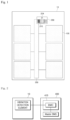
FIG. 1 is a battery pack according to an embodiment of the present invention. -
FIG. 2 is a battery module according to an embodiment of the present invention and a battery pack including the same. -
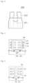
FIG. 3 is a configuration diagram of a fuse according to the present invention. -
FIG. 4 is a configuration diagram of a fuse box according to the present invention. -
FIG. 5 is a configuration diagram of a fuse case according to the present invention except for a fuse cover. -
FIG. 6 illustrates a battery pack according to another embodiment of the present invention. - Hereinafter, with reference to the accompanying drawings, embodiments of the present invention will be described in detail. However, the present invention is not limited to the embodiments disclosed below, and will be implemented in various different forms. The embodiments of the present invention are provided only to make the disclosure of the present invention complete, and to fully inform the scope of the invention to a person with ordinary knowledge in the art. In order to explain the embodiment of the present invention, the drawings may be exaggerated, parts irrelevant to the description may be omitted from the drawings, and the same reference numerals in the drawings refer to the same elements.
- Hereinafter, an embodiment of the present invention will be described with reference to the drawings.
- Referring to
Figure 1 , the present invention is configured with abattery pack 10 including abattery module 100, afuse box 200, which includes afuse 210, a fuse case 220 (seeFigure 5 ), and a vibration detection element 230 (seeFigure 4 or 5 ), and abus bar 300, and a battery management system (BMS) 400 (seeFigure 2 ) that controls thebattery pack 10. - The
battery module 100 is configured by connecting a plurality of battery cells in series with or in parallel to each other, and at least one of thesebattery modules 100 is connected to configure thebattery pack 10. The plurality of battery cells may be configured as cylindrical, pouch, and prismatic battery cells. In addition, the type of the battery cell may include, but is not limited to, a lithium ion battery, a lithium polymer battery, a nickel cadmium battery, and a nickel hydride battery. -
FIG. 4 illustrates a configuration of thefuse box 200 of the present invention. Thefuse box 200 is configured with afuse 210, a fuse case in which thefuse 210 is accommodated, and thevibration detection element 230 attached to one surface of the fuse case, and facilitates coupling and disengagement of the fuse during operation such as fuse exchange. Thefuse box 200 may be disposed inside thebattery pack 10 at a position between a terminal of eachbattery module 100 and thebus bar 300 to which thefuse box 200 is connected, and may also accommodate a plurality offuses 210 so as to be disposed at one end of thebus bar 300 connected to the outside of thebattery pack 10. - The
fuse box 200 may be formed at a portion where an electrode terminal of the battery pack and the bus bar are connected as illustrated inFIG. 1 , or may be formed at a connection portion betweenrespective battery modules 100 and the bus bar as illustrated inFIG. 6 . - When formed as illustrated in
FIG. 1 , one end of thebus bar 300 is connected to the BMS 400 ofFIG. 2 . In this case, a fuse case-battery terminal of thefuse box 200 and one end of thebus bar 300 may be connected, and the BMS 400 may be connected to afuse case terminal 224. - When describing with reference to
FIGS. 3 to 6 , although thefuse boxes 200 are illustrated as being connected between eachbattery module 100 and thebus bar 300, anadditional fuse box 200 may be disposed to connect one end of thebus bar 300 and the electrode terminal (not illustrated) of thebattery pack 10. - The
fuse 210 is configured to be coupled to a circuit through which the charging/discharging current of thebattery module 100 flows, and is coupled between thebattery module 100 and thebus bar 300 to connect each of the at least one ormore battery modules 100 to thebus bar 300 through thefuse 210. When connected to thefuse box 200, thebus bar 300 and the electrode terminal (not illustrated) of thebattery pack 10 or thebus bar 300 and theexternal BMS 400 are connected through thefuse 210. - The
fuse 210 may be accommodated in thefuse box 200 and positioned at each connection portion connected between thebattery module 100 and thebus bar 300. A plurality offuses 210 may be accommodated in onefuse box 200 and positioned at one end of thebus bar 300 connected to the external terminal (an electrode terminal or a terminal connected to BMS) of thebattery pack 10. -
FIG. 3 illustrates a detailed configuration of thefuse 210. - The
fuse 210 is configured to include afuse terminal 212 and is inserted into the fuse case to be connected to the fuse case-battery terminal 222 (seeFigure 4 or 5 ) to couple thebattery module 100 to an external device and the battery management system. - The
fuse 210 is made of metal such as copper and tin. In thefuse 210, when an overcurrent flows through thebattery module 100 or the circuit of the pack, afuse breakage part 211 is melted to block thebattery module 100 from the overcurrent. - In the
fuse 210, when continuous vibration from the outside occurs, thefuse breakage part 211 is physically broken, which may cause the phenomenon of insensitivity in relation to thebattery pack 10 and thus lose an overcurrent blocking function, thereby causing a problem in user safety. Thevibration detection element 230 of the present invention detects vibration from the outside in order to prevent or detect the loss of the overcurrent blocking function in advance. -
FIG. 5 illustrates a structure of thefuse case 220. The fuse case ofFIG. 5 may have a structure covered with afuse cover 221 as illustrated inFIG. 4 . The fuse case is provided with thefuse cover 221 including a fuse accommodation part capable of accommodating thefuse 210 therein, and afuse case terminal 224 is formed inside the fuse accommodation part. - In the case of the disposition illustrated in
FIG. 6 , thebus bar 300 is connected to one end of thefuse case terminal 224, and the terminal of thebattery modules 100 is connected to the fuse case-battery terminal 222, and thus thebus bar 300 and thebattery module 100 are connected through thefuse 210. - In the case of the disposition as illustrated in
FIG. 1 , thebus bar 300 is connected to the fuse case-battery terminal 222, thefuse case terminal 224 is connected to theBMS 400, and thus thefuse 210 is disposed to form a path between thebus bar 300 and theBMS 400. Alternatively, in contrast to this, a configuration in which one end of thebus bar 300 is connected to thefuse case terminal 224 and the fuse case-battery terminal 222 is connected to theBMS 400 may be adopted. - Conventionally, abnormalities such as disconnection of the circuit connecting the
fuse 210 or thebattery module 100 and thebus bar 300 could occur due to the breakage of the fuse case. When a problem with thefuse 210 occurs, thebattery module 100 or the pack is not blocked from overcurrent or the phenomenon of insensitivity to power of thebattery pack 10 is caused, thereby causing a problem in the stability of a user who uses thebattery pack 10. - The
vibration detection element 230 is mounted at a position where the vibration from the outside of thebattery pack 10 is delivered more sensitively to thefuse 210 in a process of being delivered to the inside and is attached to detect the vibration. - The
vibration detection element 230 is disposed to be insulated from each of the wires/fuses in the fuse box. - The
vibration detection element 230 may be configured to directly detect vibration applied to thefuse 210 by being disposed to be in physical contact with thefuse 210 while maintaining an electrically insulated state with thefuse 210. Thevibration detection element 230 may be configured to detect vibration of the fuse box by being disposed on thefuse case terminal 224 as illustrated inFIGS. 4 and 5 or disposed on one surface of thefuse case 220. In addition, thevibration detection element 230 may be configured to directly detect vibration applied to the fuse by being disposed on one surface of thefuse cover 221. - When the
fuse box 200 accommodates a plurality offuses 210 and is positioned on one side of thebus bar 300 connected to the outside of thebattery pack 10, vibration may flow into thefuse 210 and thefuse box 200 in a process in which the vibration delivered from the outside through thebus bar 300 is delivered to the inside of the pack. Accordingly, thevibration detection element 230 may be attached to be positioned on at least one surface of thefuse box 200 so as to detect the vibration flowing into thebus bar 300. - When the
fuse box 200 accommodates onefuse 210 and is positioned to be connected between the terminal of thebattery module 100 and thebus bar 300, each of thebattery modules 100 is connected to thebus bar 300 through a plurality offuses 210. Therefore, when vibration generated outside thebattery pack 10 flows into thebattery pack 10 through thebus bar 300, the vibration is also delivered to thefuse 210 and thefuse box 200 before being delivered to thebattery module 100. Accordingly, thevibration detection element 230 may be attached to each of the plurality offuse boxes 200 to detect vibration delivered to thefuse box 200 connected to the terminal of thebattery module 100. - When the
vibration detection element 230 described above is mounted on thebattery pack 10 for a vehicle, the purpose of thevibration detection element 230 is to detect vibration and vibration delivered to thefuse box 200 during driving. Therefore, thevibration detection element 230 is transferred in a form of a tape or in a form of a flexible protection circuit board (FPCB) transferred on a flexible substrate, and thus it is possible to sensitively detect that vibration generated during driving of a vehicle flows into thefuse box 200 and thebus bar 300 even a momentary moment, and to continuously detect vibration without being damaged even by a temporary impact. - As illustrated in
FIG. 2 , thevibration detection element 230 is directly connected to aCMC 410 of theBMS 400 with a ring terminal or a wire harness connection structure through terminals formed at both ends thereof, and is connected to amaster BMS 400 through a BMIC 411 of theCMC 410 and delivers a change in resistance due to detected vibration to theBMS 400. -
FIGS. 1 and6 illustrate a configuration of thebus bar 300. Although only onebus bar 300 is illustrated in the drawing, negative/positive bus bars to which the module terminals (negative/positive terminals) of thebattery modules 100 are respectively connected may be formed, and one end thereof is connected to an external electrode terminal (not illustrated) of thebattery pack 10 - The
bus bar 300 may electrically connect the at least onebattery module 100 to each other through a module terminal (not illustrated), and may be electrically coupled to eachbattery module 100 through thefuse 210. - The
bus bar 300 is connected to the fuse case-bus bar terminal 223 through thefuse case terminal 224 of thefuse box 200. One end of thebus bar 300 is partially exposed to the outside of thebattery pack 10 to be connected to the external electrical equipment of thebattery pack 10 and is connected to the BMS, and through this, vibration from the outside of thebattery pack 10 is delivered to the inside of the pack. In addition, when vibrations are accumulated, cumulative damage may occur. In thebus bar 300, a portion thereof connected to thefuse box 200 or theexternal BMS 400 may be damaged due to vibration generated outside thebattery pack 10 such as driving of a vehicle and accumulated damage resulting therefrom, thereby causing a communication error with thebattery module 100. - The
vibration detection element 230 is mounted on one surface of thefuse box 200 including a plurality offuses 210 as described above, but, in contrast to this, when thevibration detection element 230 is not positioned on one surface of thebus bar 300, in order to prevent damage due to accumulated damage caused by vibrations flowing into thebus bar 300, thevibration detection element 230 may also be attached to one end of thebus bar 300 connected to theexternal BMS 400. -
FIG. 2 illustrates a connection relationship between thebattery pack 10 and theBMS 400. - The
BMS 400 may be formed separately from the battery pack or formed inside the battery pack. When theBMS 400 is formed separately from thebattery pack 10, thebattery pack 10 is limited to a configuration including thebattery modules 100 and thebus bar 300 connecting themodules 100. - The
BMS 400 may be configured to be included in each module as a module BMS, and in this case, at least one module BMS functions as a master BMS 420. - The
BMS 400 collectively refers to a battery management system, and includes a cell monitoring circuit (CMC) 410, a battery monitoring circuit (BMIC) 411 which is a battery monitoring IC, and the Master BMS 420 that manages the entire system. - The
CMC 410 is a circuit inserted into thebattery module 100 and is connected to thevibration detection element 230 through the internal BMIC 411 to check a state of the battery cell. - The BMIC 411 is directly connected to both ends of the
vibration detection element 230 to monitor the change in the voltage value due to vibration or mechanical deformation of thefuse box 200 and thebus bar 300, and delivers detected information to the Master BMS 420. - The master BMS 420 is a BMS that manages the entire battery system, and communicates with the vehicle through MCU, and receives voltage value change information according to vibration or mechanical deformation of the battery cell and the module by the
vibration detection element 230 from the BMIC 411 of theCMC 410. By classifying the voltage value into a predetermined reference level according to the maximum allowable deformation specification of thevibration detection element 230, the protection operation of thebattery pack 10 may be performed according to a range of detected vibration, and an alarm may be transmitted to the user. - For example, a first level based on an initial state level that is a level of the vibration detection element in a state before deformation, a second level that is the maximum allowable level of deformation, and third and fourth levels that exceed the maximum allowable level of deformation may be designated as reference levels. When vibration detected by the vibration detection element exceeds the second level, an alarm may be transmitted to the user, when the third level is exceeded, the alarm is transmitted, the battery is charged and discharged, and the vehicle is operated below a rated rating, and when the fourth level is exceeded, it is determined, by the user, that
vibration detection element 230 is damaged and a measurement impossible alarm may be transmitted. The detection level reference and detection time according to the change in the resistance value of thevibration detection element 230 may be changed according to a user's request. - Meanwhile, configurations indicated by the reference numerals used in the drawings of the present invention are as follows.
-
- 10: battery pack
- 100: battery module
- 200: fuse box
- 210: fuse
- 211: fuse breakage part
- 212: fuse terminal
- 220: fuse case
- 221: fuse cover
- 222: fuse case-battery terminal
- 223: fuse case-bus bar terminal
- 224: fuse case terminal
- 230: vibration detection element
- 300: bus bar
- 400: BMS
- 410: CMC
- 411: BMIC
- 420: Master BMS
Claims (10)
- A battery pack comprising:one or more battery modules provided with a plurality of battery cells;a bus bar connected to a module terminal of the battery module to electrically connect the one or more battery modules; anda fuse box in which a fuse is accommodated, whereinthe fuse box is configured to include a vibration detection element which is insulated and attached to one surface of the fuse box or one surface of the bus bar to detect vibration flowing into the battery pack.
- The battery pack of claim 1, wherein
the vibration detection element is attached to the bus bar or the fuse box in a form of a tape or a form of an FPCB transferred on a flexible substrate to detect inflow of vibration. - The battery pack of claim 1, wherein
the fuse box is disposed at a connection portion between the bus bar and the module terminal of the battery module to form a path between the bus bar and the battery module. - The battery pack of claim 3, whereinthe fuse box is configured to includea fuse case-battery terminal connected to the module terminal of the battery module;a fuse case terminal connected to the bus bar; andthe fuse connecting the fuse case-battery terminal and the fuse case terminal, andconnects the battery module and the bus bar through the fuse.
- The battery pack of claim 1, wherein
the fuse box is disposed at one end of the bus bar to form a path between the bus bar and a BMS. - The battery pack of claim 5, whereinthe fuse box is configured to includea fuse case-battery terminal connected to the BMS,a fuse case terminal connected to one end of the bus bar, andthe fuse connecting the fuse case-battery terminal and the fuse case terminal, andconnects the bus bar and the BMS and the battery module and the bus bar through the fuse.
- The battery pack of claim 4 or 6, wherein
the vibration detection element is disposed so as to be insulated on a fuse case-bus bar terminal extending from the fuse case terminal. - The battery pack of claim 4 or 6, wherein
the vibration detection element is insulated so as to physically contact the fuse. - The battery pack of claim 4 or 6, whereinthe fuse box includes a fuse cover covering the fuse, andthe vibration detection element is disposed on one surface of the fuse cover.
- The battery pack of claim 1, whereinthe vibration detection element measures a change in voltage value according to vibration detection of the bus bar and the fuse box and delivers the voltage value to a BMS, andthe BMS compares the voltage value with a predetermined reference level, and performs a protection operation and transmits an alarm to a user when the voltage value exceeds a maximum allowable level at the predetermined reference level.
Applications Claiming Priority (2)
| Application Number | Priority Date | Filing Date | Title |
|---|---|---|---|
| KR1020210034141A KR20220129354A (en) | 2021-03-16 | 2021-03-16 | Fuse box vibration detection protection circuit |
| PCT/KR2022/003488 WO2022197018A1 (en) | 2021-03-16 | 2022-03-11 | Protective circuit for sensing vibration of fuse box |
Publications (2)
| Publication Number | Publication Date |
|---|---|
| EP4293796A1 true EP4293796A1 (en) | 2023-12-20 |
| EP4293796A4 EP4293796A4 (en) | 2025-05-07 |
Family
ID=83320815
Family Applications (1)
| Application Number | Title | Priority Date | Filing Date |
|---|---|---|---|
| EP22771684.2A Pending EP4293796A4 (en) | 2021-03-16 | 2022-03-11 | PROTECTION CIRCUIT FOR DETECTING THE VIBRATION OF A FUSE BOX |
Country Status (5)
| Country | Link |
|---|---|
| US (1) | US20240170819A1 (en) |
| EP (1) | EP4293796A4 (en) |
| KR (1) | KR20220129354A (en) |
| CN (1) | CN116998043A (en) |
| WO (1) | WO2022197018A1 (en) |
Families Citing this family (1)
| Publication number | Priority date | Publication date | Assignee | Title |
|---|---|---|---|---|
| CN119495525B (en) * | 2025-01-16 | 2025-03-18 | 浙江豪钿科技有限公司 | Electric door lock with weak current starting and mechanical starting functions for electric vehicle |
Family Cites Families (10)
| Publication number | Priority date | Publication date | Assignee | Title |
|---|---|---|---|---|
| KR100801852B1 (en) * | 2005-04-21 | 2008-02-11 | 주식회사 엘지화학 | Battery pack protection device and method |
| KR101056238B1 (en) * | 2009-11-30 | 2011-08-11 | 삼성에스디아이 주식회사 | Battery pack |
| BR112015004301A2 (en) * | 2012-08-29 | 2017-07-04 | Honda Access Kk | system to monitor a vehicle's battery |
| KR102029210B1 (en) | 2013-03-26 | 2019-10-07 | 에스케이이노베이션 주식회사 | Battery pack deformation detecting device using knock sensor and Method for detecting deformation |
| JP6277057B2 (en) * | 2014-05-13 | 2018-02-07 | デクセリアルズ株式会社 | Battery pack, battery system, and discharging method |
| JP6780385B2 (en) * | 2016-09-02 | 2020-11-04 | トヨタ自動車株式会社 | Busbar for batteries |
| KR102265844B1 (en) * | 2016-12-22 | 2021-06-17 | 주식회사 엘지화학 | Method and apparatus for impact protection of battery pack |
| KR102456321B1 (en) | 2017-11-08 | 2022-10-19 | 삼성전기주식회사 | Printed circuit board and electronic component package having the same |
| KR102655770B1 (en) | 2018-07-25 | 2024-04-05 | 주식회사 엘지에너지솔루션 | Battery pack and vehicle comprising the battery pack |
| JP7062180B2 (en) | 2019-01-18 | 2022-05-06 | エルジー エナジー ソリューション リミテッド | Battery management device and method |
-
2021
- 2021-03-16 KR KR1020210034141A patent/KR20220129354A/en active Pending
-
2022
- 2022-03-11 US US18/282,454 patent/US20240170819A1/en active Pending
- 2022-03-11 EP EP22771684.2A patent/EP4293796A4/en active Pending
- 2022-03-11 CN CN202280021889.4A patent/CN116998043A/en active Pending
- 2022-03-11 WO PCT/KR2022/003488 patent/WO2022197018A1/en not_active Ceased
Also Published As
| Publication number | Publication date |
|---|---|
| KR20220129354A (en) | 2022-09-23 |
| WO2022197018A1 (en) | 2022-09-22 |
| US20240170819A1 (en) | 2024-05-23 |
| CN116998043A (en) | 2023-11-03 |
| EP4293796A4 (en) | 2025-05-07 |
Similar Documents
| Publication | Publication Date | Title |
|---|---|---|
| KR101047831B1 (en) | Safety component by fuse at high voltage battery sensing line | |
| KR101473397B1 (en) | Apparatus and method for checking current sensor abnormality in battery pack | |
| KR101404712B1 (en) | Battery Pack of Improved Safety | |
| KR101815876B1 (en) | Battery pack with apparatus to prevent surge current | |
| KR102249889B1 (en) | Protection apparutus for rechargeable battery | |
| CN104380563B (en) | The battery management system of the robustness with the raising for negative voltage | |
| KR20130126918A (en) | Battery management system for a power supply system with a low-voltage region and a high-voltage region | |
| KR20130081215A (en) | Power supply device | |
| KR20110060166A (en) | Battery pack | |
| EP2589104A1 (en) | Battery pack and power tool | |
| CN114976495B (en) | Thermal protection of connectors | |
| KR100809453B1 (en) | Charge / discharge monitoring system for multi-parallel and multi-series lithium secondary battery packs | |
| JP5194669B2 (en) | Power storage system | |
| US20240170819A1 (en) | Protective circuit for sensing vibration of fuse box | |
| US12609423B2 (en) | Relay control system and battery system | |
| JP4633615B2 (en) | Battery pack and method of charging the battery pack | |
| WO2021206373A1 (en) | Battery module and energy storage system | |
| EP3471172B1 (en) | Disconnectable bus bar for a battery system and battery system including the same | |
| CN119489690A (en) | Method for detecting dielectric breakdown in a battery module, battery system and vehicle including the battery system | |
| CN220653745U (en) | CTP structure pack in-package integrated BDU | |
| EP4557446A2 (en) | Rechargeable battery and rechargeable battery module | |
| CN223797457U (en) | Electrical compartment, battery pack, and vehicle | |
| KR101826863B1 (en) | Middle or Large-Sized Battery Pack Available for Direct Charging and Charging Station to be Connected to the Same | |
| KR102441487B1 (en) | A battery module assembly with a built-in wireless cell sensing unit that has excellent communication reliability and is removable and integrated in both parts, and a battery system assembly including the same | |
| EP4726853A1 (en) | Systems and methods for detecting thermal runaway |
Legal Events
| Date | Code | Title | Description |
|---|---|---|---|
| STAA | Information on the status of an ep patent application or granted ep patent |
Free format text: STATUS: THE INTERNATIONAL PUBLICATION HAS BEEN MADE |
|
| PUAI | Public reference made under article 153(3) epc to a published international application that has entered the european phase |
Free format text: ORIGINAL CODE: 0009012 |
|
| STAA | Information on the status of an ep patent application or granted ep patent |
Free format text: STATUS: REQUEST FOR EXAMINATION WAS MADE |
|
| 17P | Request for examination filed |
Effective date: 20230914 |
|
| AK | Designated contracting states |
Kind code of ref document: A1 Designated state(s): AL AT BE BG CH CY CZ DE DK EE ES FI FR GB GR HR HU IE IS IT LI LT LU LV MC MK MT NL NO PL PT RO RS SE SI SK SM TR |
|
| DAV | Request for validation of the european patent (deleted) | ||
| DAX | Request for extension of the european patent (deleted) | ||
| A4 | Supplementary search report drawn up and despatched |
Effective date: 20250407 |
|
| RIC1 | Information provided on ipc code assigned before grant |
Ipc: H01M 50/569 20210101ALI20250401BHEP Ipc: H01M 50/296 20210101ALI20250401BHEP Ipc: H01M 50/211 20210101ALI20250401BHEP Ipc: H01M 50/209 20210101ALI20250401BHEP Ipc: H01M 50/204 20210101ALI20250401BHEP Ipc: H01H 85/20 20060101ALI20250401BHEP Ipc: G01H 1/00 20060101ALI20250401BHEP Ipc: H01M 50/242 20210101ALI20250401BHEP Ipc: G01R 19/165 20060101ALI20250401BHEP Ipc: G01H 11/06 20060101ALI20250401BHEP Ipc: H01H 85/143 20060101ALI20250401BHEP Ipc: H01H 85/165 20060101ALI20250401BHEP Ipc: H01M 10/42 20060101ALI20250401BHEP Ipc: H01M 50/583 20210101ALI20250401BHEP Ipc: H01M 10/48 20060101AFI20250401BHEP |
|
| GRAP | Despatch of communication of intention to grant a patent |
Free format text: ORIGINAL CODE: EPIDOSNIGR1 |
|
| STAA | Information on the status of an ep patent application or granted ep patent |
Free format text: STATUS: GRANT OF PATENT IS INTENDED |
|
| INTG | Intention to grant announced |
Effective date: 20260210 |
|
| P01 | Opt-out of the competence of the unified patent court (upc) registered |
Free format text: CASE NUMBER: UPC_APP_0009386_4293796/2026 Effective date: 20260311 |
|
| GRAS | Grant fee paid |
Free format text: ORIGINAL CODE: EPIDOSNIGR3 |
|
| GRAA | (expected) grant |
Free format text: ORIGINAL CODE: 0009210 |
|
| STAA | Information on the status of an ep patent application or granted ep patent |
Free format text: STATUS: THE PATENT HAS BEEN GRANTED |