EP4293771A1 - Electrode assembly and secondary battery comprising same - Google Patents
Electrode assembly and secondary battery comprising same Download PDFInfo
- Publication number
- EP4293771A1 EP4293771A1 EP22896150.4A EP22896150A EP4293771A1 EP 4293771 A1 EP4293771 A1 EP 4293771A1 EP 22896150 A EP22896150 A EP 22896150A EP 4293771 A1 EP4293771 A1 EP 4293771A1
- Authority
- EP
- European Patent Office
- Prior art keywords
- electrode
- electrode assembly
- coated portion
- bent
- present specification
- Prior art date
- Legal status (The legal status is an assumption and is not a legal conclusion. Google has not performed a legal analysis and makes no representation as to the accuracy of the status listed.)
- Granted
Links
Images



Classifications
-
- H—ELECTRICITY
- H01—ELECTRIC ELEMENTS
- H01M—PROCESSES OR MEANS, e.g. BATTERIES, FOR THE DIRECT CONVERSION OF CHEMICAL ENERGY INTO ELECTRICAL ENERGY
- H01M4/00—Electrodes
- H01M4/02—Electrodes composed of, or comprising, active material
- H01M4/13—Electrodes for accumulators with non-aqueous electrolyte, e.g. for lithium-accumulators; Processes of manufacture thereof
-
- H—ELECTRICITY
- H01—ELECTRIC ELEMENTS
- H01M—PROCESSES OR MEANS, e.g. BATTERIES, FOR THE DIRECT CONVERSION OF CHEMICAL ENERGY INTO ELECTRICAL ENERGY
- H01M4/00—Electrodes
- H01M4/02—Electrodes composed of, or comprising, active material
- H01M4/64—Carriers or collectors
- H01M4/70—Carriers or collectors characterised by shape or form
- H01M4/78—Shapes other than plane or cylindrical, e.g. helical
-
- H—ELECTRICITY
- H01—ELECTRIC ELEMENTS
- H01M—PROCESSES OR MEANS, e.g. BATTERIES, FOR THE DIRECT CONVERSION OF CHEMICAL ENERGY INTO ELECTRICAL ENERGY
- H01M10/00—Secondary cells; Manufacture thereof
- H01M10/04—Construction or manufacture in general
- H01M10/0431—Cells with wound or folded electrodes
-
- H—ELECTRICITY
- H01—ELECTRIC ELEMENTS
- H01M—PROCESSES OR MEANS, e.g. BATTERIES, FOR THE DIRECT CONVERSION OF CHEMICAL ENERGY INTO ELECTRICAL ENERGY
- H01M10/00—Secondary cells; Manufacture thereof
- H01M10/05—Accumulators with non-aqueous electrolyte
- H01M10/052—Li-accumulators
-
- H—ELECTRICITY
- H01—ELECTRIC ELEMENTS
- H01M—PROCESSES OR MEANS, e.g. BATTERIES, FOR THE DIRECT CONVERSION OF CHEMICAL ENERGY INTO ELECTRICAL ENERGY
- H01M10/00—Secondary cells; Manufacture thereof
- H01M10/05—Accumulators with non-aqueous electrolyte
- H01M10/052—Li-accumulators
- H01M10/0525—Rocking-chair batteries, i.e. batteries with lithium insertion or intercalation in both electrodes; Lithium-ion batteries
-
- H—ELECTRICITY
- H01—ELECTRIC ELEMENTS
- H01M—PROCESSES OR MEANS, e.g. BATTERIES, FOR THE DIRECT CONVERSION OF CHEMICAL ENERGY INTO ELECTRICAL ENERGY
- H01M10/00—Secondary cells; Manufacture thereof
- H01M10/42—Methods or arrangements for servicing or maintenance of secondary cells or secondary half-cells
- H01M10/4235—Safety or regulating additives or arrangements in electrodes, separators or electrolyte
-
- H—ELECTRICITY
- H01—ELECTRIC ELEMENTS
- H01M—PROCESSES OR MEANS, e.g. BATTERIES, FOR THE DIRECT CONVERSION OF CHEMICAL ENERGY INTO ELECTRICAL ENERGY
- H01M4/00—Electrodes
- H01M4/02—Electrodes composed of, or comprising, active material
- H01M4/36—Selection of substances as active materials, active masses, active liquids
- H01M4/362—Composites
- H01M4/366—Composites as layered products
-
- H—ELECTRICITY
- H01—ELECTRIC ELEMENTS
- H01M—PROCESSES OR MEANS, e.g. BATTERIES, FOR THE DIRECT CONVERSION OF CHEMICAL ENERGY INTO ELECTRICAL ENERGY
- H01M4/00—Electrodes
- H01M4/02—Electrodes composed of, or comprising, active material
- H01M4/64—Carriers or collectors
- H01M4/66—Selection of materials
- H01M4/665—Composites
- H01M4/667—Composites in the form of layers, e.g. coatings
-
- H—ELECTRICITY
- H01—ELECTRIC ELEMENTS
- H01M—PROCESSES OR MEANS, e.g. BATTERIES, FOR THE DIRECT CONVERSION OF CHEMICAL ENERGY INTO ELECTRICAL ENERGY
- H01M50/00—Constructional details or processes of manufacture of the non-active parts of electrochemical cells other than fuel cells, e.g. hybrid cells
- H01M50/50—Current conducting connections for cells or batteries
- H01M50/531—Electrode connections inside a battery casing
- H01M50/533—Electrode connections inside a battery casing characterised by the shape of the leads or tabs
-
- H—ELECTRICITY
- H01—ELECTRIC ELEMENTS
- H01M—PROCESSES OR MEANS, e.g. BATTERIES, FOR THE DIRECT CONVERSION OF CHEMICAL ENERGY INTO ELECTRICAL ENERGY
- H01M50/00—Constructional details or processes of manufacture of the non-active parts of electrochemical cells other than fuel cells, e.g. hybrid cells
- H01M50/50—Current conducting connections for cells or batteries
- H01M50/531—Electrode connections inside a battery casing
- H01M50/538—Connection of several leads or tabs of wound or folded electrode stacks
-
- H—ELECTRICITY
- H01—ELECTRIC ELEMENTS
- H01M—PROCESSES OR MEANS, e.g. BATTERIES, FOR THE DIRECT CONVERSION OF CHEMICAL ENERGY INTO ELECTRICAL ENERGY
- H01M50/00—Constructional details or processes of manufacture of the non-active parts of electrochemical cells other than fuel cells, e.g. hybrid cells
- H01M50/50—Current conducting connections for cells or batteries
- H01M50/572—Means for preventing undesired use or discharge
- H01M50/584—Means for preventing undesired use or discharge for preventing incorrect connections inside or outside the batteries
- H01M50/59—Means for preventing undesired use or discharge for preventing incorrect connections inside or outside the batteries characterised by the protection means
- H01M50/595—Tapes
-
- H—ELECTRICITY
- H01—ELECTRIC ELEMENTS
- H01M—PROCESSES OR MEANS, e.g. BATTERIES, FOR THE DIRECT CONVERSION OF CHEMICAL ENERGY INTO ELECTRICAL ENERGY
- H01M10/00—Secondary cells; Manufacture thereof
- H01M10/05—Accumulators with non-aqueous electrolyte
- H01M10/058—Construction or manufacture
- H01M10/0587—Construction or manufacture of accumulators having only wound construction elements, i.e. wound positive electrodes, wound negative electrodes and wound separators
-
- H—ELECTRICITY
- H01—ELECTRIC ELEMENTS
- H01M—PROCESSES OR MEANS, e.g. BATTERIES, FOR THE DIRECT CONVERSION OF CHEMICAL ENERGY INTO ELECTRICAL ENERGY
- H01M50/00—Constructional details or processes of manufacture of the non-active parts of electrochemical cells other than fuel cells, e.g. hybrid cells
- H01M50/10—Primary casings; Jackets or wrappings
- H01M50/102—Primary casings; Jackets or wrappings characterised by their shape or physical structure
- H01M50/107—Primary casings; Jackets or wrappings characterised by their shape or physical structure having curved cross-section, e.g. round or elliptic
-
- Y—GENERAL TAGGING OF NEW TECHNOLOGICAL DEVELOPMENTS; GENERAL TAGGING OF CROSS-SECTIONAL TECHNOLOGIES SPANNING OVER SEVERAL SECTIONS OF THE IPC; TECHNICAL SUBJECTS COVERED BY FORMER USPC CROSS-REFERENCE ART COLLECTIONS [XRACs] AND DIGESTS
- Y02—TECHNOLOGIES OR APPLICATIONS FOR MITIGATION OR ADAPTATION AGAINST CLIMATE CHANGE
- Y02E—REDUCTION OF GREENHOUSE GAS [GHG] EMISSIONS, RELATED TO ENERGY GENERATION, TRANSMISSION OR DISTRIBUTION
- Y02E60/00—Enabling technologies; Technologies with a potential or indirect contribution to GHG emissions mitigation
- Y02E60/10—Energy storage using batteries
-
- Y—GENERAL TAGGING OF NEW TECHNOLOGICAL DEVELOPMENTS; GENERAL TAGGING OF CROSS-SECTIONAL TECHNOLOGIES SPANNING OVER SEVERAL SECTIONS OF THE IPC; TECHNICAL SUBJECTS COVERED BY FORMER USPC CROSS-REFERENCE ART COLLECTIONS [XRACs] AND DIGESTS
- Y02—TECHNOLOGIES OR APPLICATIONS FOR MITIGATION OR ADAPTATION AGAINST CLIMATE CHANGE
- Y02P—CLIMATE CHANGE MITIGATION TECHNOLOGIES IN THE PRODUCTION OR PROCESSING OF GOODS
- Y02P70/00—Climate change mitigation technologies in the production process for final industrial or consumer products
- Y02P70/50—Manufacturing or production processes characterised by the final manufactured product
Definitions
- the present specification relates to an electrode assembly and a secondary battery including the same.
- positive and negative electrodes each have one or two tabs used as conductive paths.
- the improvement on resistance is limited because there is a problem in that resistance increases as a physical distance from the tab increases.
- Electrode active material non-coated regions (non-coated portions) on upper and lower portions of an electrode current collector, superimposes the electrode active material non-coated regions (non-coated portions) after a notching process, and use the electrode active material non-coated regions (non-coated portions) as tabs.
- FIG. 2 there is a problem in that a part of a positive electrode non-coated portion 110 is folded inward and comes into contact with a negative electrode 130, which causes a short circuit. Accordingly, there is a need to solve the problem.
- An object of the present invention is to change a method of folding a non-coated portion of an electrode of an electrode assembly, thereby removing a likelihood of a short circuit caused by the method of folding the non-coated portion of the electrode in the related art.
- An embodiment of the present specification provides an electrode assembly including a first electrode, a separator, and a second electrode, in which the first electrode includes: a current collector; and an electrode active material layer provided on the current collector, in which an edge portion of the current collector provided at one end of a winding axis of the electrode assembly includes a non-coated portion on which no electrode active material layer is provided, and in which a non-coated portion of the first electrode is bent one or more times in a direction from a winding center of an electrode assembly toward an outer periphery of the electrode assembly.
- the non-coated portion may include a plurality of segmental pieces, and each of the plurality of segmental pieces may be bent one or more times in the direction from the winding center of the electrode assembly toward the outer periphery of the electrode assembly.
- a segmental piece of the non-coated portion of the plurality of segmental pieces on the outer periphery of the electrode assembly may be bent twice so as to face a lateral surface of the electrode assembly.
- At least a part of a segmental piece of the plurality of segmental pieces of the non-coated portion may adjoin at least a part of the bent portion of an adjacent segmental piece of the plurality of segmental piece in a radial direction.
- a length from an initially bent portion of the non-coated portion of the first electrode to an end of the non-coated portion of the first electrode may be 1 mm or more.
- the segmental piece on the outer periphery of the electrode assembly may adjoin the lateral surface of the electrode assembly by 1% or more and 30% or less of an overall height of the electrode assembly.
- the first electrode may be a positive electrode
- the second electrode may be a negative electrode
- the first electrode may be exposed to the outside with respect to an upper surface of the electrode assembly.
- the first electrode may further include an insulation tape provided on a surface opposite to a surface facing the lateral surface of the electrode assembly.
- the embodiment of the present specification provides a secondary battery including the electrode assembly, a battery can configured to accommodate the electrode assembly, and a cap assembly coupled to an upper portion of the battery can.
- the non-coated portion of the electrode is bent one or more times in the direction from the winding center of the electrode assembly toward the outer periphery of the electrode assembly, which makes it possible to prevent an internal short circuit caused by contact between the positive electrode non-coated portion and the negative electrode.
- the term "on” not only means that a layer is positioned on one layer while being in physical contact with the layer but also means that a layer is positioned above one layer. That is, still another layer may be present between one layer and another layer positioned on one layer.
- An electrode assembly 10 is a jelly-roll type electrode assembly having a structure in which first and second electrodes, which each have a sheet shape, and a separator, which is interposed between the first and second electrodes, are wound in one direction.
- the electrode assembly 10 is an electrode assembly made by winding a stack of a first electrode 110, a separator 120, and a second electrode 130.
- the first electrode 110 includes a current collector 111 and an electrode active material layer 112 provided on the current collector 111.
- An edge portion of the current collector 111 provided at one end of a winding axis of the electrode assembly 10 includes a non-coated portion 113 on which the electrode active material layer 112 is not provided.
- the non-coated portion 113 of the first electrode is bent one or more times in a direction P from a winding center of the electrode assembly 10 toward an outer periphery of the electrode assembly 10.
- the non-coated portion 113 of the first electrode is bent one or more times at an angle of 30° to 90° in the direction P from the winding center of the electrode assembly toward the outer periphery of the electrode assembly.
- FIG. 3 illustrates the direction P from the winding center of the electrode assembly toward the outer periphery of the electrode assembly.
- a region of the current collector on which no electrode active material layer is formed is a non-coated portion (not illustrated in the drawings), and the non-coated portion means a region in which a positive electrode current collector or a negative electrode current collector is exposed.
- a separate electrode tab is not coupled to the non-coated portion of the first electrode. At least a part of the non-coated portion may be used as an electrode tab as it is.
- the first electrode 110 may be a positive electrode, and the second electrode 130 may be a negative electrode.
- the first electrode 110 may be exposed to the outside with respect to an upper surface of the electrode assembly.
- the first and second electrodes 110 and 130 each include the current collector 111, and the electrode active material layer 112 provided on the current collector 111.
- the electrode active material layer 112 includes an electrode active material.
- any electrode active material publicly known in the art may be used without limitation.
- the positive electrode active material may include lithium cobalt oxide having high working voltage and excellent capacity characteristics, lithium nickel oxide having high reversible capacity and used to easily implement a high-capacity battery, lithium nickel cobalt oxide made by substituting a part of nickel with cobalt, lithium nickel cobalt metal oxide made by substituting a part of nickel with manganese, cobalt, or aluminum, lithium manganese-based oxide having excellent thermal stability and made with low costs, and lithium iron phosphate having excellent stability.
- the negative electrode active material may be crystalline carbon, amorphous carbon, carbon composite body, carbon material such as carbon fiber, silicon, lithium metal, lithium alloy, or the like.
- the separator 120 is positioned between the positive and negative electrodes while having predetermined mechanical strength, and the separator 120 is made of a porous material to facilitate the movement of ions between the electrodes.
- the separator 120 may be made of any one material selected from a group consisting of polyethylene (PE), polystyrene (PS), polypropylene (PP), and a copolymer of polyethylene (PE) and polypropylene (PP).
- a method of bending the non-coated portion of the first electrode of the electrode assembly is performed by applying pressure by using a bending device.
- the non-coated portion of the first electrode is bent by being wound toward the outer periphery of the electrode assembly in the winding direction of the electrode assembly by using the bending device.
- the non-coated portion of the first electrode which is at least provided on the outermost periphery of the electrode assembly, may be bent by inertia by using the bending device.
- the non-coated portion of the first electrode may be bent once by using the bending device, and then the non-coated portion of the first electrode at least provided on the outermost periphery of the electrode assembly may be additionally bent by a taping process using an insulation tape.
- the electrode assembly may be coupled to a cylindrical hollow holder, which has an opened bottom and a closed ceiling, to induce additional bending, and then the non-coated portion of the first electrode may be formed by the taping process using the insulation tape.
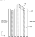
- FIG. 3 is a view illustrating a bending shape and a bending direction of the positive electrode non-coated portion of the electrode assembly.
- the positive electrode 110 illustrated in FIG. 3 may include all an electrode active material layer (not illustrated), an insulating coating layer (not illustrated), and a non-coated portion (not illustrated).
- the electrode assembly includes the positive electrode 110, the separator 120, and the negative electrode 130.
- the non-coated portion of the positive electrode 110 has a shape bent in the direction from the winding center of the electrode assembly toward the outer periphery of the electrode assembly.
- the non-coated portion of the positive electrode provided on the outermost periphery of the electrode assembly is bent twice so as to faces a lateral surface of the electrode assembly.
- the non-coated portions are provided on upper and lower portions of the electrode current collector, superimposed after the notching process, and then used as tabs.
- a bending direction of a positive electrode non-coated portion is a direction toward a winding center of an electrode assembly in the related art.
- FIG. 2 in the present specification there is a problem in that a part of the positive electrode non-coated portion is folded inward and comes into contact with a negative electrode, which causes a short circuit.
- the non-coated portion of the positive electrode has a shape bent in the direction from the winding center of the electrode assembly toward the outer periphery of the electrode assembly, which makes it possible to prevent an internal short circuit caused by contact between the positive electrode non-coated portion and the negative electrode.
- the non-coated portion of the first electrode includes a plurality of segmental pieces 113.
- the plurality of segmental pieces 113 may be bent one or more times in the direction P from the winding center of the electrode assembly toward the outer periphery of the electrode assembly.
- the non-coated portion of the first electrode may include the plurality of notched segmental pieces 113. That is, the non-coated portion of the first electrode may be provided in the form of a serrated wheel.
- FIG. 4 is a view schematically illustrating that the non-coated portion 113 of the first electrode includes the plurality of segmental pieces, and the non-coated portion 113, which does not have the electrode active material layer 112, is segmented and provided in the form of a serrated wheel.
- FIG. 4 is a view illustrating that the segmental pieces are spaced apart from one another.
- the shape, the length, and the spacing distance of the segmental piece are not limited thereto.
- the plurality of segmental pieces 113 may have the same height, width, or spacing distance or different heights, widths, or spacing distances.
- a length of each of the plurality of segmental pieces 113 may be 4 mm to 20 mm.
- the length of the segmental piece 113 may mean a vertical distance from a boundary between the non-coated portion 113 and the electrode active material layer 112 of the current collector 111 to a distal end of the non-coated portion.
- the length of the segmental piece is short, which makes it possible to prevent the segmental piece from entering the electrode assembly and causing a short circuit when the segmental piece is bent.
- the length of each of the plurality of segmental pieces 113 may be 4 mm to 15 mm.
- the length of each of the plurality of segmental pieces 113 may be 6 mm to 10 mm.
- a spacing distance between any one segmental piece 113 and another adjacent segmental piece, among the plurality of segmental pieces may be 1 mm to 150 mm.
- resistance of the electrode may be appropriately maintained, gas is easily discharged at the time of injecting an electrolyte, and gas trapping may be less generated when the battery is used after battery activation.
- the spacing distance between any one segmental piece 113 and another adjacent segmental piece, among the plurality of segmental pieces may be 1 mm to 48 mm.
- the spacing distance between any one segmental piece 113 and another adjacent segmental piece, among the plurality of segmental pieces may be 5 mm to 36 mm.
- a width of the segmental piece 113 may be 2 mm to 30 mm.
- the segmental piece of the non-coated portion of the first electrode 115 at least provided on the outermost periphery of the electrode assembly may be bent twice so as to face the lateral surface of the electrode assembly.
- the segmental piece of the non-coated portion of the first electrode 115 at least provided on the outermost periphery of the electrode assembly may be bent twice so as to face the lateral surface of the electrode assembly 10 and thus have a ' ' or 'U' shape.
- the non-coated portion of the first electrode 115 at least provided on the outermost periphery of the electrode assembly is bent twice, it is possible to prevent a short circuit caused by contact between the positive electrode non-coated portion and the negative electrode and improve structural stability when the first electrode 110 is used as the positive electrode.
- At least a part of the bent portion of the non-coated portion may adjoin at least a part of the bent portion of the adjacent non-coated portion.
- adjacent may mean a positional relationship between one non-coated portion and another non-coated portion close to one non-coated portion and does not mean only physical contact. Specifically, the term “adjacent” may mean a positional relationship between one non-coated portion and another non-coated portion closest to one non-coated portion.
- a width (a) of an area in which at least a part of the bent portion of the non-coated portion and at least a part of the bent portion of the adjacent non-coated portion adjoin each other may be larger than a width (b) of the first electrode. In this case, it is possible to further improve structural stability
- a length from an initially bent portion of the non-coated portion to the end of the non-coated portion may be 1 mm or more. In case that the length is satisfied, it is possible to prevent a short circuit caused by contact between the electrodes.
- the length from the initially bent portion of the non-coated portion to the end of the non-coated portion may be 2 mm or more.
- the length from the initially bent portion of the non-coated portion to the end of the non-coated portion may be 4 mm or more.
- the length from the initially bent portion of the non-coated portion to the end of the non-coated portion may be 5 mm or more.
- the length from the initially bent portion of the non-coated portion to the end of the non-coated portion may be 10 mm or more.
- the non-coated portion which is bent twice, may adjoin the lateral surface of the electrode assembly by 1% or more of an overall height of the electrode assembly.
- the overall height of the electrode assembly means a maximum length in a winding axis direction of the electrode assembly and means a length in a y direction in FIG. 3 .
- the non-coated portion which is bent twice, may adjoin the lateral surface of the electrode assembly by 2% or more of the overall height of the electrode assembly.
- the non-coated portion which is bent twice, may adjoin the lateral surface of the electrode assembly by 3% or more of the overall height of the electrode assembly.
- the non-coated portion which is bent twice, may adjoin the lateral surface of the electrode assembly by 4% or more of the overall height of the electrode assembly.
- the non-coated portion which is bent twice, may adjoin the lateral surface of the electrode assembly by 5% or more of the overall height of the electrode assembly.
- the non-coated portion which is bent twice, may adjoin the lateral surface of the electrode assembly by 30% or less of the overall height of the electrode assembly.
- the non-coated portion which is bent twice, may adjoin the lateral surface of the electrode assembly by 25% or less of the overall height of the electrode assembly.
- the non-coated portion which is bent twice, may adjoin the lateral surface of the electrode assembly by 20% or less of the overall height of the electrode assembly.
- the non-coated portion which is bent twice, may adjoin the lateral surface of the electrode assembly by 15% or less of the overall height of the electrode assembly.
- the non-coated portion which is bent twice, may adjoin the lateral surface of the electrode assembly by 10% or less of the overall height of the electrode assembly.
- the non-coated portion bent twice, a height of a portion of the non-coated portion, which faces the lateral surface of the electrode assembly may be 1% or more and 30% or less of the overall height of the electrode assembly.
- the first electrode 110 may further include insulation tape 140 provided on a surface opposite to the surface facing the lateral surface of the electrode assembly.
- the insulation tape 140 may prevent the non-coated portion of the first electrode, which is bent twice and exposed to the lateral surface of the electrode assembly, from coming into contact with the battery can, thereby preventing a short circuit.
- FIG. 3 illustrates a position at which the insulation tape 140 is provided on the non-coated portion bent twice.
- the position at which the insulation tape is provided is not limited thereto.
- the insulation tape 140 may be provided to surround a region from a portion where the non-coated portion of the first electrode is bent twice to an end of the non-coated portion.
- the insulation tape 140 may be provided to surround both the portion where the non-coated portion of the first electrode is bent twice and the adjacent separator.
- any material of the insulation tape 140 which is an insulation material publicly known in the art, may be used without limitation.
- the material of the insulation tape 140 may include polyamide, polyacetal, polycarbonate, polyethylene terephthalate, or rubber.
- the first electrode 110 and the second electrode 130 may further include an insulating coating layer 114 configured to cover a boundary between the electrode active material layer 112 and the non-coated portion 113.
- the insulating coating layer 114 contains polymer resin with insulation and may further selectively include an inorganic filler.
- the insulating coating layer 114 serves to prevent an end of the electrode active material layer 112 from coming into contact with an active material layer having an opposite polarity and facing the electrode active material layer 112 through the separator.
- the insulating coating layer 114 serves to structurally support the bent portion of the segmental piece 113.
- the second electrode 120 includes the current collector, and the electrode active material layer provided on the current collector.
- An edge portion of the current collector provided at the other end of the winding axis of the electrode assembly may include the non-coated portion on which no electrode active material layer is provided.
- the second electrode 120 may be a negative electrode.
- the electrode active material which is used for the electrode active material layer of the second electrode, is identical to the negative electrode active material.
- Another embodiment of the present specification provides a secondary battery including the electrode assembly, a battery can configured to accommodate the electrode assembly, and a cap assembly coupled to an upper portion of the battery can.
- the electrode assembly which is provided in the form of a wound jelly roll, may be inserted into the battery can.
- the battery can accommodate the electrode assembly therein and be made of stainless steel, aluminum (Al), or the like.
- the material of the battery may be selected from materials that may have low reactivity, protect the battery can from external impact, allow the battery can to accommodate the electrode assembly and the electrolyte therein.
- the battery can may have a cylindrical shape.
- a diameter of a circle of each of the two opposite ends of the battery can may be 30 mm to 55 mm, and a height of the battery can may be 60 mm to 120 mm.
- a value of circular diameter x height of the cylindrical battery can may be 40 mm x 60 mm, 40 mm x 80 mm, 40 mm x 90 mm, or 40 mm x 120 mm.
- the cap assembly may include a circuit board, an insulating gasket, and the like and seal the battery can by being coupled to an upper portion of the battery can.
- the secondary battery may further include an upper current collecting plate provided on the electrode assembly.
- the upper current collecting plate may be coupled to the electrode assembly by welding.
- the current collecting plate of the secondary battery may be coupled to the cap assembly.
- the secondary battery may further include a lower current collecting plate provided on a lower portion of the electrode assembly.
- the lower current collecting plate may be electrically coupled to the battery can. That is, the lower current collecting plate may be provided between the electrode assembly and the battery can.
- the lower current collecting plate may be electrically coupled to the non-coated portion of the second electrode of the electrode assembly.
- Another embodiment of the present invention provides a battery module and a battery pack that include the secondary battery according to the above-mentioned embodiment.
Landscapes
- Chemical & Material Sciences (AREA)
- Chemical Kinetics & Catalysis (AREA)
- Electrochemistry (AREA)
- General Chemical & Material Sciences (AREA)
- Engineering & Computer Science (AREA)
- Manufacturing & Machinery (AREA)
- Materials Engineering (AREA)
- Composite Materials (AREA)
- Secondary Cells (AREA)
- Battery Electrode And Active Subsutance (AREA)
- Connection Of Batteries Or Terminals (AREA)
- Sealing Battery Cases Or Jackets (AREA)
Abstract
Description
- The present specification relates to an electrode assembly and a secondary battery including the same.
- This application claims priority to and the benefit of
Korean Patent Application No. 10-2021-0160355 filed with the Korean Intellectual Property Office on November 19, 2021 - Recently, there has been an increasing need for batteries capable of implementing high capacities and high outputs. According to the environmental-friendly policy, electric vehicle markets have been rapidly grown, and thus high performance has been required for the batteries.
- In the case of a cylindrical secondary battery, thicknesses of current collectors or separators and sizes or shapes of cans and top caps are changed and optimized to place a large number of electrodes into a limited space. However, this optimization reaches a limit level within the limited size.
- In the case of the cylindrical secondary battery in the related art, positive and negative electrodes each have one or two tabs used as conductive paths. In this case, the improvement on resistance is limited because there is a problem in that resistance increases as a physical distance from the tab increases.
- To solve the problem, there is a method that forms electrode active material non-coated regions (non-coated portions) on upper and lower portions of an electrode current collector, superimposes the electrode active material non-coated regions (non-coated portions) after a notching process, and use the electrode active material non-coated regions (non-coated portions) as tabs. In this case, as illustrated in
FIG. 2 , there is a problem in that a part of a positive electrode non-coatedportion 110 is folded inward and comes into contact with anegative electrode 130, which causes a short circuit. Accordingly, there is a need to solve the problem. - An object of the present invention is to change a method of folding a non-coated portion of an electrode of an electrode assembly, thereby removing a likelihood of a short circuit caused by the method of folding the non-coated portion of the electrode in the related art.
- An embodiment of the present specification provides an electrode assembly including a first electrode, a separator, and a second electrode, in which the first electrode includes: a current collector; and an electrode active material layer provided on the current collector, in which an edge portion of the current collector provided at one end of a winding axis of the electrode assembly includes a non-coated portion on which no electrode active material layer is provided, and in which a non-coated portion of the first electrode is bent one or more times in a direction from a winding center of an electrode assembly toward an outer periphery of the electrode assembly.
- In addition, in the embodiment of the present specification, the non-coated portion may include a plurality of segmental pieces, and each of the plurality of segmental pieces may be bent one or more times in the direction from the winding center of the electrode assembly toward the outer periphery of the electrode assembly.
- In addition, in the embodiment of the present specification, a segmental piece of the non-coated portion of the plurality of segmental pieces on the outer periphery of the electrode assembly may be bent twice so as to face a lateral surface of the electrode assembly.
- In addition, in the embodiment of the present specification, at least a part of a segmental piece of the plurality of segmental pieces of the non-coated portion may adjoin at least a part of the bent portion of an adjacent segmental piece of the plurality of segmental piece in a radial direction.
- In addition, in the embodiment of the present specification, a length from an initially bent portion of the non-coated portion of the first electrode to an end of the non-coated portion of the first electrode may be 1 mm or more.
- In addition, in the embodiment of the present specification, the segmental piece on the outer periphery of the electrode assembly may adjoin the lateral surface of the electrode assembly by 1% or more and 30% or less of an overall height of the electrode assembly.
- In addition, in the embodiment of the present specification, the first electrode may be a positive electrode, the second electrode may be a negative electrode, and the first electrode may be exposed to the outside with respect to an upper surface of the electrode assembly.
- In addition, in the embodiment of the present specification, the first electrode may further include an insulation tape provided on a surface opposite to a surface facing the lateral surface of the electrode assembly.
- In addition, the embodiment of the present specification provides a secondary battery including the electrode assembly, a battery can configured to accommodate the electrode assembly, and a cap assembly coupled to an upper portion of the battery can.
- According to the electrode assembly according to the embodiment of the present specification, the non-coated portion of the electrode is bent one or more times in the direction from the winding center of the electrode assembly toward the outer periphery of the electrode assembly, which makes it possible to prevent an internal short circuit caused by contact between the positive electrode non-coated portion and the negative electrode.
-
-
FIG. 1 is a schematic view illustrating a direction in which a positive electrode non-coated portion in the related art is bent from an outer periphery of an electrode assembly toward a winding center of the electrode assembly. -
FIG. 2 is a schematic view illustrating that a short circuit occurs when the positive electrode non-coated portion is bent inward by an upward load and comes into contact with a negative electrode in case that the positive electrode non-coated portion is bent from the outer periphery of the electrode assembly toward the winding center of the electrode assembly. -
FIG. 3 is a schematic view illustrating a bending shape and a bending direction of a positive electrode non-coated portion of an electrode assembly according to an embodiment of the present specification. -
FIG. 4 is a schematically illustrating that a non-coated portion of a first electrode includes a plurality of segmental pieces. -
- 110: First electrode, positive electrode
- 111: Current collector
- 112: Electrode active material layer
- 113: Non-coated portion, segmental piece
- 114: Insulating coating layer
- 115: First electrode provided on outermost periphery of electrode assembly
- 120: Separator
- 130: Second electrode, negative electrode
- 140: Insulation tape
- a: Width of area in which at least a part of bent portion of non-coated portion and at least a part of bent portion of adjacent non-coated portion adjoin each other
- b: Width of first electrode
- P: Direction from winding center of electrode assembly toward outer periphery of electrode assembly
- Hereinafter, the present specification will be described in more detail.
- Hereinafter, exemplary embodiments of the present invention will be described in detail with reference to the accompanying drawings. In addition, terms or words used in the specification and the claims should not be interpreted as being limited to a general or dictionary meaning and should be interpreted as a meaning and a concept which conform to the technical spirit of the present invention based on a principle that an inventor can appropriately define a concept of a term in order to describe his/her own invention by the best method.
- Therefore, the embodiments disclosed in the present specification and the configurations illustrated in the drawings are just the best preferred embodiments of the present invention and do not represent all the technical spirit of the present invention. Accordingly, it should be appreciated that various equivalents and modified examples capable of substituting the embodiments may be made at the time of filing the present application.
- In addition, to help understand the present invention, the accompanying drawings are not illustrated based on actual scales, but some constituent elements may be exaggerated in dimension. In addition, the constituent elements in different embodiments may be assigned with the same reference numerals.
- In the present specification, the term "on" not only means that a layer is positioned on one layer while being in physical contact with the layer but also means that a layer is positioned above one layer. That is, still another layer may be present between one layer and another layer positioned on one layer.
- In the specification, unless explicitly described to the contrary, the word "comprise" or "include" and variations, such as "comprises", "comprising", "includes" or "including", will be understood to imply the inclusion of stated constituent elements, not the exclusion of any other constituent elements.
- An
electrode assembly 10 according to the present specification is a jelly-roll type electrode assembly having a structure in which first and second electrodes, which each have a sheet shape, and a separator, which is interposed between the first and second electrodes, are wound in one direction. - In the embodiment of the present specification, the
electrode assembly 10 is an electrode assembly made by winding a stack of afirst electrode 110, aseparator 120, and asecond electrode 130. Thefirst electrode 110 includes acurrent collector 111 and an electrodeactive material layer 112 provided on thecurrent collector 111. An edge portion of thecurrent collector 111 provided at one end of a winding axis of theelectrode assembly 10 includes anon-coated portion 113 on which the electrodeactive material layer 112 is not provided. Thenon-coated portion 113 of the first electrode is bent one or more times in a direction P from a winding center of theelectrode assembly 10 toward an outer periphery of theelectrode assembly 10. - In the embodiment of the present specification, the
non-coated portion 113 of the first electrode is bent one or more times at an angle of 30° to 90° in the direction P from the winding center of the electrode assembly toward the outer periphery of the electrode assembly. -
FIG. 3 illustrates the direction P from the winding center of the electrode assembly toward the outer periphery of the electrode assembly. - A region of the current collector on which no electrode active material layer is formed is a non-coated portion (not illustrated in the drawings), and the non-coated portion means a region in which a positive electrode current collector or a negative electrode current collector is exposed.
- In this case, a separate electrode tab is not coupled to the non-coated portion of the first electrode. At least a part of the non-coated portion may be used as an electrode tab as it is.
- In the embodiment of the present specification, the
first electrode 110 may be a positive electrode, and thesecond electrode 130 may be a negative electrode. Thefirst electrode 110 may be exposed to the outside with respect to an upper surface of the electrode assembly. - In the embodiment of the present specification, the first and
second electrodes current collector 111, and the electrodeactive material layer 112 provided on thecurrent collector 111. The electrodeactive material layer 112 includes an electrode active material. - In this case, any electrode active material publicly known in the art may be used without limitation.
- For example, the positive electrode active material may include lithium cobalt oxide having high working voltage and excellent capacity characteristics, lithium nickel oxide having high reversible capacity and used to easily implement a high-capacity battery, lithium nickel cobalt oxide made by substituting a part of nickel with cobalt, lithium nickel cobalt metal oxide made by substituting a part of nickel with manganese, cobalt, or aluminum, lithium manganese-based oxide having excellent thermal stability and made with low costs, and lithium iron phosphate having excellent stability.
- For example, the negative electrode active material may be crystalline carbon, amorphous carbon, carbon composite body, carbon material such as carbon fiber, silicon, lithium metal, lithium alloy, or the like.
- The
separator 120 is positioned between the positive and negative electrodes while having predetermined mechanical strength, and theseparator 120 is made of a porous material to facilitate the movement of ions between the electrodes. For example, theseparator 120 may be made of any one material selected from a group consisting of polyethylene (PE), polystyrene (PS), polypropylene (PP), and a copolymer of polyethylene (PE) and polypropylene (PP). - In the embodiment of the present specification, a method of bending the non-coated portion of the first electrode of the electrode assembly is performed by applying pressure by using a bending device.
- Specifically, the non-coated portion of the first electrode is bent by being wound toward the outer periphery of the electrode assembly in the winding direction of the electrode assembly by using the bending device. The non-coated portion of the first electrode, which is at least provided on the outermost periphery of the electrode assembly, may be bent by inertia by using the bending device.
- More specifically, the non-coated portion of the first electrode may be bent once by using the bending device, and then the non-coated portion of the first electrode at least provided on the outermost periphery of the electrode assembly may be additionally bent by a taping process using an insulation tape. Alternatively, the electrode assembly may be coupled to a cylindrical hollow holder, which has an opened bottom and a closed ceiling, to induce additional bending, and then the non-coated portion of the first electrode may be formed by the taping process using the insulation tape.
-
FIG. 3 is a view illustrating a bending shape and a bending direction of the positive electrode non-coated portion of the electrode assembly. Thepositive electrode 110 illustrated inFIG. 3 may include all an electrode active material layer (not illustrated), an insulating coating layer (not illustrated), and a non-coated portion (not illustrated). - As illustrated in
FIG. 3 , the electrode assembly according to the embodiment of the present specification includes thepositive electrode 110, theseparator 120, and thenegative electrode 130. The non-coated portion of thepositive electrode 110 has a shape bent in the direction from the winding center of the electrode assembly toward the outer periphery of the electrode assembly. In particular, the non-coated portion of the positive electrode provided on the outermost periphery of the electrode assembly is bent twice so as to faces a lateral surface of the electrode assembly. - The non-coated portions are provided on upper and lower portions of the electrode current collector, superimposed after the notching process, and then used as tabs. As illustrated in
FIG. 1 in the present specification, a bending direction of a positive electrode non-coated portion is a direction toward a winding center of an electrode assembly in the related art. In this case, as indicated by the dotted circle illustrated inFIG. 2 in the present specification, there is a problem in that a part of the positive electrode non-coated portion is folded inward and comes into contact with a negative electrode, which causes a short circuit. - In the present invention, as illustrated in
FIG. 3 , the non-coated portion of the positive electrode has a shape bent in the direction from the winding center of the electrode assembly toward the outer periphery of the electrode assembly, which makes it possible to prevent an internal short circuit caused by contact between the positive electrode non-coated portion and the negative electrode. - In the embodiment of the present specification, the non-coated portion of the first electrode includes a plurality of
segmental pieces 113. The plurality ofsegmental pieces 113 may be bent one or more times in the direction P from the winding center of the electrode assembly toward the outer periphery of the electrode assembly. - In the embodiment of the present specification, the non-coated portion of the first electrode may include the plurality of notched
segmental pieces 113. That is, the non-coated portion of the first electrode may be provided in the form of a serrated wheel.FIG. 4 is a view schematically illustrating that thenon-coated portion 113 of the first electrode includes the plurality of segmental pieces, and thenon-coated portion 113, which does not have the electrodeactive material layer 112, is segmented and provided in the form of a serrated wheel.FIG. 4 is a view illustrating that the segmental pieces are spaced apart from one another. However, the shape, the length, and the spacing distance of the segmental piece are not limited thereto. - In the embodiment of the present specification, the plurality of
segmental pieces 113 may have the same height, width, or spacing distance or different heights, widths, or spacing distances. - In the embodiment of the present specification, a length of each of the plurality of
segmental pieces 113 may be 4 mm to 20 mm. - The length of the
segmental piece 113 may mean a vertical distance from a boundary between thenon-coated portion 113 and the electrodeactive material layer 112 of thecurrent collector 111 to a distal end of the non-coated portion. - In case that the range of length is satisfied, the length of the segmental piece is short, which makes it possible to prevent the segmental piece from entering the electrode assembly and causing a short circuit when the segmental piece is bent.
- In the embodiment of the present specification, the length of each of the plurality of
segmental pieces 113 may be 4 mm to 15 mm. - In the embodiment of the present specification, the length of each of the plurality of
segmental pieces 113 may be 6 mm to 10 mm. - In the embodiment of the present specification, a spacing distance between any one
segmental piece 113 and another adjacent segmental piece, among the plurality of segmental pieces, may be 1 mm to 150 mm. - In case that the range of spacing distance is satisfied, resistance of the electrode may be appropriately maintained, gas is easily discharged at the time of injecting an electrolyte, and gas trapping may be less generated when the battery is used after battery activation.
- In the embodiment of the present specification, the spacing distance between any one
segmental piece 113 and another adjacent segmental piece, among the plurality of segmental pieces, may be 1 mm to 48 mm. - In the embodiment of the present specification, the spacing distance between any one
segmental piece 113 and another adjacent segmental piece, among the plurality of segmental pieces, may be 5 mm to 36 mm. - In the embodiment of the present specification, a width of the
segmental piece 113 may be 2 mm to 30 mm. - In case that the above-mentioned range is satisfied, welding and bending may be easily performed.
- In the embodiment of the present specification, the segmental piece of the non-coated portion of the
first electrode 115 at least provided on the outermost periphery of the electrode assembly may be bent twice so as to face the lateral surface of the electrode assembly. - In the embodiment of the present specification, as illustrated in
FIG. 3 , the segmental piece of the non-coated portion of thefirst electrode 115 at least provided on the outermost periphery of the electrode assembly may be bent twice so as to face the lateral surface of theelectrode assembly 10 and thus have a '' or 'U' shape.
- Because the non-coated portion of the
first electrode 115 at least provided on the outermost periphery of the electrode assembly is bent twice, it is possible to prevent a short circuit caused by contact between the positive electrode non-coated portion and the negative electrode and improve structural stability when thefirst electrode 110 is used as the positive electrode. - In the embodiment of the present specification, at least a part of the bent portion of the non-coated portion may adjoin at least a part of the bent portion of the adjacent non-coated portion.
- The term "adjacent" may mean a positional relationship between one non-coated portion and another non-coated portion close to one non-coated portion and does not mean only physical contact. Specifically, the term "adjacent" may mean a positional relationship between one non-coated portion and another non-coated portion closest to one non-coated portion.
- In case that at least a part of the bent portion of the non-coated portion adjoins at least a part of the bent portion of the adjacent non-coated portion, an internal short circuit may be prevented because the non-coated portion does not come into contact with the negative electrode.
- In the embodiment of the present specification, a width (a) of an area in which at least a part of the bent portion of the non-coated portion and at least a part of the bent portion of the adjacent non-coated portion adjoin each other may be larger than a width (b) of the first electrode. In this case, it is possible to further improve structural stability
- In the embodiment of the present specification, a length from an initially bent portion of the non-coated portion to the end of the non-coated portion may be 1 mm or more. In case that the length is satisfied, it is possible to prevent a short circuit caused by contact between the electrodes.
- In the embodiment of the present specification, the length from the initially bent portion of the non-coated portion to the end of the non-coated portion may be 2 mm or more.
- In the embodiment of the present specification, the length from the initially bent portion of the non-coated portion to the end of the non-coated portion may be 4 mm or more.
- In the embodiment of the present specification, the length from the initially bent portion of the non-coated portion to the end of the non-coated portion may be 5 mm or more.
- In the embodiment of the present specification, the length from the initially bent portion of the non-coated portion to the end of the non-coated portion may be 10 mm or more.
- In the embodiment of the present specification, the non-coated portion, which is bent twice, may adjoin the lateral surface of the electrode assembly by 1% or more of an overall height of the electrode assembly.
- In the present specification, the overall height of the electrode assembly means a maximum length in a winding axis direction of the electrode assembly and means a length in a y direction in
FIG. 3 . - In the embodiment of the present specification, the non-coated portion, which is bent twice, may adjoin the lateral surface of the electrode assembly by 2% or more of the overall height of the electrode assembly.
- In the embodiment of the present specification, the non-coated portion, which is bent twice, may adjoin the lateral surface of the electrode assembly by 3% or more of the overall height of the electrode assembly.
- In the embodiment of the present specification, the non-coated portion, which is bent twice, may adjoin the lateral surface of the electrode assembly by 4% or more of the overall height of the electrode assembly.
- In the embodiment of the present specification, the non-coated portion, which is bent twice, may adjoin the lateral surface of the electrode assembly by 5% or more of the overall height of the electrode assembly.
- In the embodiment of the present specification, the non-coated portion, which is bent twice, may adjoin the lateral surface of the electrode assembly by 30% or less of the overall height of the electrode assembly.
- In the embodiment of the present specification, the non-coated portion, which is bent twice, may adjoin the lateral surface of the electrode assembly by 25% or less of the overall height of the electrode assembly.
- In the embodiment of the present specification, the non-coated portion, which is bent twice, may adjoin the lateral surface of the electrode assembly by 20% or less of the overall height of the electrode assembly.
- In the embodiment of the present specification, the non-coated portion, which is bent twice, may adjoin the lateral surface of the electrode assembly by 15% or less of the overall height of the electrode assembly.
- In the embodiment of the present specification, the non-coated portion, which is bent twice, may adjoin the lateral surface of the electrode assembly by 10% or less of the overall height of the electrode assembly.
- In the embodiment of the present specification, the non-coated portion bent twice, a height of a portion of the non-coated portion, which faces the lateral surface of the electrode assembly, may be 1% or more and 30% or less of the overall height of the electrode assembly.
- In the embodiment of the present specification, the
first electrode 110 may further includeinsulation tape 140 provided on a surface opposite to the surface facing the lateral surface of the electrode assembly. Theinsulation tape 140 may prevent the non-coated portion of the first electrode, which is bent twice and exposed to the lateral surface of the electrode assembly, from coming into contact with the battery can, thereby preventing a short circuit.FIG. 3 illustrates a position at which theinsulation tape 140 is provided on the non-coated portion bent twice. However, the position at which the insulation tape is provided is not limited thereto. - In the embodiment of the present specification, the
insulation tape 140 may be provided to surround a region from a portion where the non-coated portion of the first electrode is bent twice to an end of the non-coated portion. - In the embodiment of the present specification, the
insulation tape 140 may be provided to surround both the portion where the non-coated portion of the first electrode is bent twice and the adjacent separator. - Any material of the
insulation tape 140, which is an insulation material publicly known in the art, may be used without limitation. For example, the material of theinsulation tape 140 may include polyamide, polyacetal, polycarbonate, polyethylene terephthalate, or rubber. - In the embodiment of the present specification, as illustrated in
FIG. 4 , thefirst electrode 110 and thesecond electrode 130 may further include an insulatingcoating layer 114 configured to cover a boundary between the electrodeactive material layer 112 and thenon-coated portion 113. The insulatingcoating layer 114 contains polymer resin with insulation and may further selectively include an inorganic filler. - The insulating
coating layer 114 serves to prevent an end of the electrodeactive material layer 112 from coming into contact with an active material layer having an opposite polarity and facing the electrodeactive material layer 112 through the separator. The insulatingcoating layer 114 serves to structurally support the bent portion of thesegmental piece 113. - In the embodiment of the present specification, the
second electrode 120 includes the current collector, and the electrode active material layer provided on the current collector. An edge portion of the current collector provided at the other end of the winding axis of the electrode assembly may include the non-coated portion on which no electrode active material layer is provided. - In the embodiment of the present specification, the
second electrode 120 may be a negative electrode. - The electrode active material, which is used for the electrode active material layer of the second electrode, is identical to the negative electrode active material.
- Another embodiment of the present specification provides a secondary battery including the electrode assembly, a battery can configured to accommodate the electrode assembly, and a cap assembly coupled to an upper portion of the battery can.
- The electrode assembly, which is provided in the form of a wound jelly roll, may be inserted into the battery can.
- The battery can may accommodate the electrode assembly therein and be made of stainless steel, aluminum (Al), or the like. However, the present invention is not necessarily limited thereto. The material of the battery can may be selected from materials that may have low reactivity, protect the battery can from external impact, allow the battery can to accommodate the electrode assembly and the electrolyte therein.
- The battery can may have a cylindrical shape. A diameter of a circle of each of the two opposite ends of the battery can may be 30 mm to 55 mm, and a height of the battery can may be 60 mm to 120 mm. For example, a value of circular diameter x height of the cylindrical battery can may be 40 mm x 60 mm, 40 mm x 80 mm, 40 mm x 90 mm, or 40 mm x 120 mm.
- The cap assembly may include a circuit board, an insulating gasket, and the like and seal the battery can by being coupled to an upper portion of the battery can.
- In the embodiment of the present specification, the secondary battery may further include an upper current collecting plate provided on the electrode assembly. In this case, the upper current collecting plate may be coupled to the electrode assembly by welding.
- In the embodiment of the present specification, the current collecting plate of the secondary battery may be coupled to the cap assembly.
- In the embodiment of the present specification, the secondary battery may further include a lower current collecting plate provided on a lower portion of the electrode assembly. In this case, the lower current collecting plate may be electrically coupled to the battery can. That is, the lower current collecting plate may be provided between the electrode assembly and the battery can.
- In the embodiment of the present specification, the lower current collecting plate may be electrically coupled to the non-coated portion of the second electrode of the electrode assembly.
- Another embodiment of the present invention provides a battery module and a battery pack that include the secondary battery according to the above-mentioned embodiment.
- Those skilled in the art to which the present invention pertains will implement various applications and modifications on the basis of the above-mentioned contents without departing from the scope of the present invention.
Claims (9)
- An electrode assembly comprising:a first electrode, a separator, and a second electrode,wherein the first electrode comprises:a current collector; andan electrode active material layer provided on the current collector,wherein an edge portion of the current collector provided at one end of a winding axis of the electrode assembly comprises a non-coated portion on which no electrode active material layer is provided, andwherein the non-coated portion of the first electrode is bent one or more times in a direction from a winding center of an electrode assembly toward an outer periphery of the electrode assembly.
- The electrode assembly of claim 1, wherein the non-coated portion comprises a plurality of segmental pieces, and each of the plurality of segmental pieces is bent one or more times in the direction from the winding center of the electrode assembly toward the outer periphery of the electrode assembly.
- The electrode assembly of claim 2, wherein a segmental piece of the non-coated portion of the plurality of segmental pieces on the outer periphery of the electrode assembly is bent twice so as to face a lateral surface of the electrode assembly.
- The electrode assembly of claim 2, wherein at least a part of a segmental piece of the plurality of segmental pieces of the non-coated portion adjoins at least a part of the bent portion of an adjacent segmental piece of the plurality of segmental pieces in a radial direction.
- The electrode assembly of claim 1, wherein a length from an initially bent portion of the non-coated portion of the first electrode to an end of the non-coated portion of the first electrode is 1 mm or more.
- The electrode assembly of claim 3, wherein the segmental piece on the outer periphery of the electrode assembly adjoins the lateral surface of the electrode assembly by 1% or more and 30% or less of an overall height of the electrode assembly.
- The electrode assembly of claim 1, wherein the first electrode is a positive electrode, the second electrode is a negative electrode, and the first electrode is exposed to the outside with respect to an upper surface of the electrode assembly.
- The electrode assembly of claim 3, wherein the first electrode further comprises an insulation tape provided on a surface opposite to a surface facing the lateral surface of the electrode assembly.
- A secondary battery comprising:an electrode assembly according to any one of claims 1 to 8;a battery can accommodated in the electrode assembly; anda cap assembly coupled to an upper portion of the battery can.
Applications Claiming Priority (2)
| Application Number | Priority Date | Filing Date | Title |
|---|---|---|---|
| KR20210160355 | 2021-11-19 | ||
| PCT/KR2022/018350 WO2023090953A1 (en) | 2021-11-19 | 2022-11-18 | Electrode assembly and secondary battery comprising same |
Publications (3)
| Publication Number | Publication Date |
|---|---|
| EP4293771A1 true EP4293771A1 (en) | 2023-12-20 |
| EP4293771A4 EP4293771A4 (en) | 2024-10-16 |
| EP4293771B1 EP4293771B1 (en) | 2026-02-04 |
Family
ID=86249014
Family Applications (1)
| Application Number | Title | Priority Date | Filing Date |
|---|---|---|---|
| EP22896150.4A Active EP4293771B1 (en) | 2021-11-19 | 2022-11-18 | Electrode assembly and secondary battery comprising same |
Country Status (7)
| Country | Link |
|---|---|
| US (1) | US20240162451A1 (en) |
| EP (1) | EP4293771B1 (en) |
| JP (1) | JP7670423B2 (en) |
| KR (1) | KR102883584B1 (en) |
| CN (2) | CN116154094A (en) |
| CA (1) | CA3238457A1 (en) |
| WO (1) | WO2023090953A1 (en) |
Cited By (1)
| Publication number | Priority date | Publication date | Assignee | Title |
|---|---|---|---|---|
| EP4636900A1 (en) * | 2024-04-15 | 2025-10-22 | Samsung Sdi Co., Ltd. | Cylindrical secondary battery |
Families Citing this family (5)
| Publication number | Priority date | Publication date | Assignee | Title |
|---|---|---|---|---|
| WO2023090953A1 (en) * | 2021-11-19 | 2023-05-25 | 주식회사 엘지에너지솔루션 | Electrode assembly and secondary battery comprising same |
| WO2025037890A1 (en) * | 2023-08-11 | 2025-02-20 | 주식회사 엘지에너지솔루션 | Electrode assembly, cylindrical battery, and battery pack and vehicle including same |
| KR20250070884A (en) * | 2023-11-14 | 2025-05-21 | 주식회사 엘지에너지솔루션 | Electrode assembly and secondary battery including the same |
| WO2025206543A1 (en) * | 2024-03-26 | 2025-10-02 | 삼성에스디아이 주식회사 | Electrode assembly, secondary battery comprising same, and method for manufacturing secondary battery |
| KR20260038449A (en) * | 2024-09-12 | 2026-03-19 | 삼성에스디아이 주식회사 | Secondary battery and method for manufacturing same |
Family Cites Families (17)
| Publication number | Priority date | Publication date | Assignee | Title |
|---|---|---|---|---|
| JP3470470B2 (en) * | 1995-09-27 | 2003-11-25 | ソニー株式会社 | Cylindrical secondary battery |
| JPH0992335A (en) * | 1995-09-27 | 1997-04-04 | Sony Corp | Cylindrical secondary battery |
| CN1309105C (en) * | 2003-12-24 | 2007-04-04 | 松下电器产业株式会社 | Set of electrode plates for rolled electrochemical component and a cell comprising such electrode plates |
| JP2006004729A (en) * | 2004-06-17 | 2006-01-05 | Matsushita Electric Ind Co Ltd | Electrochemical element |
| KR100599749B1 (en) * | 2004-06-23 | 2006-07-12 | 삼성에스디아이 주식회사 | Secondary Battery and Electrode Assembly Used in the Same |
| JP5082256B2 (en) * | 2006-02-23 | 2012-11-28 | パナソニック株式会社 | Sealed storage battery |
| KR20070096651A (en) * | 2006-03-27 | 2007-10-02 | 삼성에스디아이 주식회사 | Electrode Assembly for Cylindrical Lithium Secondary Battery and Cylindrical Lithium Secondary Battery Using the Same |
| WO2009110250A1 (en) * | 2008-03-07 | 2009-09-11 | パナソニック株式会社 | Lithium-ion secondary battery and manufacturing method thereof |
| KR101165507B1 (en) * | 2009-11-27 | 2012-07-13 | 삼성에스디아이 주식회사 | Secondary battery |
| US9991498B2 (en) * | 2013-09-09 | 2018-06-05 | Samsung Electronics Co., Ltd. | Electrode assembly and secondary battery including the same |
| KR101629499B1 (en) | 2013-10-14 | 2016-06-10 | 주식회사 엘지화학 | Electrode assembly and secondary battery comprising the same |
| KR102256293B1 (en) * | 2014-07-28 | 2021-05-26 | 삼성에스디아이 주식회사 | Battery pack |
| KR102654626B1 (en) * | 2016-10-27 | 2024-04-04 | 삼성에스디아이 주식회사 | Secondary battery |
| KR102712362B1 (en) * | 2018-10-12 | 2024-10-04 | 삼성에스디아이 주식회사 | Secondary battery |
| KR102920238B1 (en) * | 2020-02-13 | 2026-02-02 | 삼성에스디아이 주식회사 | Secondary battery improved collecting structure |
| JP7744502B2 (en) * | 2021-10-15 | 2025-09-25 | エルジー エナジー ソリューション リミテッド | Electrode assembly, cylindrical battery cell, battery pack including the same, and automobile |
| WO2023090953A1 (en) * | 2021-11-19 | 2023-05-25 | 주식회사 엘지에너지솔루션 | Electrode assembly and secondary battery comprising same |
-
2022
- 2022-11-18 WO PCT/KR2022/018350 patent/WO2023090953A1/en not_active Ceased
- 2022-11-18 KR KR1020220155692A patent/KR102883584B1/en active Active
- 2022-11-18 US US18/282,871 patent/US20240162451A1/en active Pending
- 2022-11-18 CA CA3238457A patent/CA3238457A1/en active Pending
- 2022-11-18 EP EP22896150.4A patent/EP4293771B1/en active Active
- 2022-11-18 JP JP2023560155A patent/JP7670423B2/en active Active
- 2022-11-21 CN CN202211452831.3A patent/CN116154094A/en active Pending
- 2022-11-21 CN CN202223093320.5U patent/CN219017700U/en active Active
Cited By (1)
| Publication number | Priority date | Publication date | Assignee | Title |
|---|---|---|---|---|
| EP4636900A1 (en) * | 2024-04-15 | 2025-10-22 | Samsung Sdi Co., Ltd. | Cylindrical secondary battery |
Also Published As
| Publication number | Publication date |
|---|---|
| WO2023090953A1 (en) | 2023-05-25 |
| KR102883584B1 (en) | 2025-11-10 |
| EP4293771A4 (en) | 2024-10-16 |
| CN219017700U (en) | 2023-05-12 |
| JP2024513023A (en) | 2024-03-21 |
| JP7670423B2 (en) | 2025-04-30 |
| US20240162451A1 (en) | 2024-05-16 |
| CA3238457A1 (en) | 2023-05-25 |
| EP4293771B1 (en) | 2026-02-04 |
| CN116154094A (en) | 2023-05-23 |
| KR20230074015A (en) | 2023-05-26 |
Similar Documents
| Publication | Publication Date | Title |
|---|---|---|
| EP4293771A1 (en) | Electrode assembly and secondary battery comprising same | |
| EP4199206A1 (en) | Riveting structure of electrode terminal, and secondary battery, battery pack, and automobile comprising same | |
| EP4258462A1 (en) | Cylindrical battery cell, battery pack and vehicle including same, and method of producing cylindrical battery cell | |
| EP4322271A1 (en) | Electrode assembly, battery cell, battery pack, and vehicle | |
| US12525653B2 (en) | Electrode assembly and secondary battery comprising same | |
| EP4354565A1 (en) | Electrode assembly, battery, and battery pack and vehicle comprising same | |
| EP4297172A1 (en) | Secondary battery, and battery pack and vehicle comprising same | |
| CN219017715U (en) | Electrode assembly, cylindrical battery cell, battery pack, and vehicle | |
| EP4576345A1 (en) | Secondary battery | |
| EP4297173A1 (en) | Secondary battery, and battery pack and vehicle comprising same | |
| EP4145611B1 (en) | Secondary battery | |
| EP4521544A1 (en) | Battery cell, battery module, battery pack, and vehicle comprising same | |
| EP4109665A1 (en) | Button-type secondary battery | |
| KR20240010442A (en) | Cylindrical battery cell, and battery pack and vehicle including the same | |
| EP4432460A1 (en) | Injector entrance structure for injecting electrolyte into cylindrical secondary battery | |
| EP4311014A1 (en) | Cylindrical secondary battery | |
| EP4164028A1 (en) | Electrode assembly and secondary battery comprising same | |
| EP4632915A1 (en) | Secondary battery | |
| KR102888918B1 (en) | Rechargeable battery | |
| EP4716000A1 (en) | Cap assembly and secondary battery comprising same | |
| EP4564546A1 (en) | Battery cell and battery cell manufacturing method | |
| EP4697489A1 (en) | Sub plate and secondary battery including same | |
| US20260066499A1 (en) | Secondary battery, device for manufacturing secondary battery, and method of manufacturing secondary battery | |
| EP4621980A1 (en) | Battery | |
| EP4657644A1 (en) | Electrode assembly, cylindrical battery, and battery pack and vehicle including same |
Legal Events
| Date | Code | Title | Description |
|---|---|---|---|
| STAA | Information on the status of an ep patent application or granted ep patent |
Free format text: STATUS: THE INTERNATIONAL PUBLICATION HAS BEEN MADE |
|
| PUAI | Public reference made under article 153(3) epc to a published international application that has entered the european phase |
Free format text: ORIGINAL CODE: 0009012 |
|
| STAA | Information on the status of an ep patent application or granted ep patent |
Free format text: STATUS: REQUEST FOR EXAMINATION WAS MADE |
|
| 17P | Request for examination filed |
Effective date: 20230912 |
|
| AK | Designated contracting states |
Kind code of ref document: A1 Designated state(s): AL AT BE BG CH CY CZ DE DK EE ES FI FR GB GR HR HU IE IS IT LI LT LU LV MC ME MK MT NL NO PL PT RO RS SE SI SK SM TR |
|
| A4 | Supplementary search report drawn up and despatched |
Effective date: 20240916 |
|
| RIC1 | Information provided on ipc code assigned before grant |
Ipc: H01M 10/0587 20100101ALI20240910BHEP Ipc: H01M 50/538 20210101ALI20240910BHEP Ipc: H01M 50/533 20210101ALI20240910BHEP Ipc: H01M 10/0525 20100101ALI20240910BHEP Ipc: H01M 10/42 20060101ALI20240910BHEP Ipc: H01M 10/04 20060101AFI20240910BHEP |
|
| DAV | Request for validation of the european patent (deleted) | ||
| DAX | Request for extension of the european patent (deleted) | ||
| GRAP | Despatch of communication of intention to grant a patent |
Free format text: ORIGINAL CODE: EPIDOSNIGR1 |
|
| STAA | Information on the status of an ep patent application or granted ep patent |
Free format text: STATUS: GRANT OF PATENT IS INTENDED |
|
| INTG | Intention to grant announced |
Effective date: 20250925 |
|
| P01 | Opt-out of the competence of the unified patent court (upc) registered |
Free format text: CASE NUMBER: UPC_APP_0012832_4293771/2025 Effective date: 20251111 |
|
| GRAS | Grant fee paid |
Free format text: ORIGINAL CODE: EPIDOSNIGR3 |
|
| GRAA | (expected) grant |
Free format text: ORIGINAL CODE: 0009210 |
|
| STAA | Information on the status of an ep patent application or granted ep patent |
Free format text: STATUS: THE PATENT HAS BEEN GRANTED |
|
| AK | Designated contracting states |
Kind code of ref document: B1 Designated state(s): AL AT BE BG CH CY CZ DE DK EE ES FI FR GB GR HR HU IE IS IT LI LT LU LV MC ME MK MT NL NO PL PT RO RS SE SI SK SM TR |
|
| REG | Reference to a national code |
Ref country code: CH Ref legal event code: F10 Free format text: ST27 STATUS EVENT CODE: U-0-0-F10-F00 (AS PROVIDED BY THE NATIONAL OFFICE) Effective date: 20260204 Ref country code: GB Ref legal event code: FG4D |
|
| REG | Reference to a national code |
Ref country code: IE Ref legal event code: FG4D |
|
| REG | Reference to a national code |
Ref country code: DE Ref legal event code: R096 Ref document number: 602022029944 Country of ref document: DE |