EP4293558A1 - Privacy setting method and apparatus for uwb detection, and electronic device - Google Patents
Privacy setting method and apparatus for uwb detection, and electronic device Download PDFInfo
- Publication number
- EP4293558A1 EP4293558A1 EP22752139.0A EP22752139A EP4293558A1 EP 4293558 A1 EP4293558 A1 EP 4293558A1 EP 22752139 A EP22752139 A EP 22752139A EP 4293558 A1 EP4293558 A1 EP 4293558A1
- Authority
- EP
- European Patent Office
- Prior art keywords
- electronic device
- control
- target
- distance
- uwb
- Prior art date
- Legal status (The legal status is an assumption and is not a legal conclusion. Google has not performed a legal analysis and makes no representation as to the accuracy of the status listed.)
- Granted
Links
Images


Classifications
-
- G—PHYSICS
- G06—COMPUTING OR CALCULATING; COUNTING
- G06F—ELECTRIC DIGITAL DATA PROCESSING
- G06F21/00—Security arrangements for protecting computers, components thereof, programs or data against unauthorised activity
- G06F21/60—Protecting data
- G06F21/62—Protecting access to data via a platform, e.g. using keys or access control rules
- G06F21/6218—Protecting access to data via a platform, e.g. using keys or access control rules to a system of files or objects, e.g. local or distributed file system or database
- G06F21/6245—Protecting personal data, e.g. for financial or medical purposes
-
- H—ELECTRICITY
- H04—ELECTRIC COMMUNICATION TECHNIQUE
- H04W—WIRELESS COMMUNICATION NETWORKS
- H04W8/00—Network data management
- H04W8/02—Processing of mobility data, e.g. registration information at HLR [Home Location Register] or VLR [Visitor Location Register]; Transfer of mobility data, e.g. between HLR, VLR or external networks
- H04W8/08—Mobility data transfer
- H04W8/16—Mobility data transfer selectively restricting mobility data tracking
-
- H—ELECTRICITY
- H04—ELECTRIC COMMUNICATION TECHNIQUE
- H04W—WIRELESS COMMUNICATION NETWORKS
- H04W12/00—Security arrangements; Authentication; Protecting privacy or anonymity
- H04W12/02—Protecting privacy or anonymity, e.g. protecting personally identifiable information [PII]
-
- G—PHYSICS
- G01—MEASURING; TESTING
- G01S—RADIO DIRECTION-FINDING; RADIO NAVIGATION; DETERMINING DISTANCE OR VELOCITY BY USE OF RADIO WAVES; LOCATING OR PRESENCE-DETECTING BY USE OF THE REFLECTION OR RERADIATION OF RADIO WAVES; ANALOGOUS ARRANGEMENTS USING OTHER WAVES
- G01S13/00—Systems using the reflection or reradiation of radio waves, e.g. radar systems; Analogous systems using reflection or reradiation of waves whose nature or wavelength is irrelevant or unspecified
- G01S13/02—Systems using reflection of radio waves, e.g. primary radar systems; Analogous systems
- G01S13/0209—Systems with very large relative bandwidth, i.e. larger than 10 %, e.g. baseband, pulse, carrier-free, ultrawideband
-
- G—PHYSICS
- G01—MEASURING; TESTING
- G01S—RADIO DIRECTION-FINDING; RADIO NAVIGATION; DETERMINING DISTANCE OR VELOCITY BY USE OF RADIO WAVES; LOCATING OR PRESENCE-DETECTING BY USE OF THE REFLECTION OR RERADIATION OF RADIO WAVES; ANALOGOUS ARRANGEMENTS USING OTHER WAVES
- G01S13/00—Systems using the reflection or reradiation of radio waves, e.g. radar systems; Analogous systems using reflection or reradiation of waves whose nature or wavelength is irrelevant or unspecified
- G01S13/02—Systems using reflection of radio waves, e.g. primary radar systems; Analogous systems
- G01S13/06—Systems determining position data of a target
- G01S13/42—Simultaneous measurement of distance and other co-ordinates
- G01S13/44—Monopulse radar, i.e. simultaneous lobing
- G01S13/4454—Monopulse radar, i.e. simultaneous lobing phase comparisons monopulse, i.e. comparing the echo signals received by an interferometric antenna arrangement
-
- G—PHYSICS
- G01—MEASURING; TESTING
- G01S—RADIO DIRECTION-FINDING; RADIO NAVIGATION; DETERMINING DISTANCE OR VELOCITY BY USE OF RADIO WAVES; LOCATING OR PRESENCE-DETECTING BY USE OF THE REFLECTION OR RERADIATION OF RADIO WAVES; ANALOGOUS ARRANGEMENTS USING OTHER WAVES
- G01S13/00—Systems using the reflection or reradiation of radio waves, e.g. radar systems; Analogous systems using reflection or reradiation of waves whose nature or wavelength is irrelevant or unspecified
- G01S13/74—Systems using reradiation of radio waves, e.g. secondary radar systems; Analogous systems
- G01S13/76—Systems using reradiation of radio waves, e.g. secondary radar systems; Analogous systems wherein pulse-type signals are transmitted
- G01S13/765—Systems using reradiation of radio waves, e.g. secondary radar systems; Analogous systems wherein pulse-type signals are transmitted with exchange of information between interrogator and responder
-
- G—PHYSICS
- G01—MEASURING; TESTING
- G01S—RADIO DIRECTION-FINDING; RADIO NAVIGATION; DETERMINING DISTANCE OR VELOCITY BY USE OF RADIO WAVES; LOCATING OR PRESENCE-DETECTING BY USE OF THE REFLECTION OR RERADIATION OF RADIO WAVES; ANALOGOUS ARRANGEMENTS USING OTHER WAVES
- G01S13/00—Systems using the reflection or reradiation of radio waves, e.g. radar systems; Analogous systems using reflection or reradiation of waves whose nature or wavelength is irrelevant or unspecified
- G01S13/87—Combinations of radar systems, e.g. primary radar and secondary radar
- G01S13/878—Combination of several spaced transmitters or receivers of known location for determining the position of a transponder or a reflector
-
- G—PHYSICS
- G01—MEASURING; TESTING
- G01S—RADIO DIRECTION-FINDING; RADIO NAVIGATION; DETERMINING DISTANCE OR VELOCITY BY USE OF RADIO WAVES; LOCATING OR PRESENCE-DETECTING BY USE OF THE REFLECTION OR RERADIATION OF RADIO WAVES; ANALOGOUS ARRANGEMENTS USING OTHER WAVES
- G01S5/00—Position-fixing by co-ordinating two or more direction or position line determinations; Position-fixing by co-ordinating two or more distance determinations
- G01S5/02—Position-fixing by co-ordinating two or more direction or position line determinations; Position-fixing by co-ordinating two or more distance determinations using radio waves
- G01S5/12—Position-fixing by co-ordinating two or more direction or position line determinations; Position-fixing by co-ordinating two or more distance determinations using radio waves by co-ordinating position lines of different shape, e.g. hyperbolic, circular, elliptical or radial
-
- H—ELECTRICITY
- H04—ELECTRIC COMMUNICATION TECHNIQUE
- H04M—TELEPHONIC COMMUNICATION
- H04M1/00—Substation equipment, e.g. for use by subscribers
- H04M1/72—Mobile telephones; Cordless telephones, i.e. devices for establishing wireless links to base stations without route selection
- H04M1/724—User interfaces specially adapted for cordless or mobile telephones
- H04M1/72448—User interfaces specially adapted for cordless or mobile telephones with means for adapting the functionality of the device according to specific conditions
-
- H—ELECTRICITY
- H04—ELECTRIC COMMUNICATION TECHNIQUE
- H04M—TELEPHONIC COMMUNICATION
- H04M1/00—Substation equipment, e.g. for use by subscribers
- H04M1/72—Mobile telephones; Cordless telephones, i.e. devices for establishing wireless links to base stations without route selection
- H04M1/724—User interfaces specially adapted for cordless or mobile telephones
- H04M1/72448—User interfaces specially adapted for cordless or mobile telephones with means for adapting the functionality of the device according to specific conditions
- H04M1/72457—User interfaces specially adapted for cordless or mobile telephones with means for adapting the functionality of the device according to specific conditions according to geographic location
-
- H—ELECTRICITY
- H04—ELECTRIC COMMUNICATION TECHNIQUE
- H04W—WIRELESS COMMUNICATION NETWORKS
- H04W4/00—Services specially adapted for wireless communication networks; Facilities therefor
- H04W4/02—Services making use of location information
- H04W4/023—Services making use of location information using mutual or relative location information between multiple location based services [LBS] targets or of distance thresholds
-
- H—ELECTRICITY
- H04—ELECTRIC COMMUNICATION TECHNIQUE
- H04W—WIRELESS COMMUNICATION NETWORKS
- H04W8/00—Network data management
- H04W8/005—Discovery of network devices, e.g. terminals
-
- H—ELECTRICITY
- H04—ELECTRIC COMMUNICATION TECHNIQUE
- H04M—TELEPHONIC COMMUNICATION
- H04M1/00—Substation equipment, e.g. for use by subscribers
- H04M1/72—Mobile telephones; Cordless telephones, i.e. devices for establishing wireless links to base stations without route selection
- H04M1/724—User interfaces specially adapted for cordless or mobile telephones
- H04M1/72448—User interfaces specially adapted for cordless or mobile telephones with means for adapting the functionality of the device according to specific conditions
- H04M1/72463—User interfaces specially adapted for cordless or mobile telephones with means for adapting the functionality of the device according to specific conditions to restrict the functionality of the device
-
- H—ELECTRICITY
- H04—ELECTRIC COMMUNICATION TECHNIQUE
- H04W—WIRELESS COMMUNICATION NETWORKS
- H04W12/00—Security arrangements; Authentication; Protecting privacy or anonymity
- H04W12/60—Context-dependent security
- H04W12/63—Location-dependent; Proximity-dependent
-
- H—ELECTRICITY
- H04—ELECTRIC COMMUNICATION TECHNIQUE
- H04W—WIRELESS COMMUNICATION NETWORKS
- H04W4/00—Services specially adapted for wireless communication networks; Facilities therefor
- H04W4/80—Services using short range communication, e.g. near-field communication [NFC], radio-frequency identification [RFID] or low energy communication
Definitions
- This application relates to the field of communication technologies, and specifically, to a privacy setting method and apparatus for UWB detection, and an electronic device.
- the electronic device can measure a distance between two devices via an ultra-wideband (ultra-wideband, UWB) module integrated in the electronic device, to implement device positioning, device finding, and the like.
- UWB ultra-wideband
- Embodiments of this application are intended to provide a privacy setting method and apparatus for UWB detection, and an electronic device, which can resolve a problem of poor safety of the electronic device performing detection via a UWB module.
- an embodiment of this application provides a privacy setting method for UWB detection, applied to an electronic device.
- the privacy setting method for UWB detection includes: in a case that a first interface is displayed, receiving a first input by a user, where the first interface includes at least one device identifier and at least one control, each device identifier is used to indicate a device that is detected by using a UWB function, each control corresponds to a privacy setting when the electronic device is detected by another device by using the UWB function, and the first input is an input by the user for a target control in the at least one control; and in response to the first input, enabling a privacy setting corresponding to the target control.
- an embodiment of this application provides a privacy setting apparatus for UWB detection.
- the privacy setting apparatus for UWB detection includes a receiving module and an enabling module.
- the receiving module is configured to: in a case that a first interface is displayed, receive a first input by a user, where the first interface includes at least one device identifier and at least one control, each device identifier is used to indicate a device that is detected by using a UWB function, each control corresponds to a privacy setting when an electronic device is detected by another device by using the UWB function, and the first input is an input by the user for a target control in the at least one control.
- the enabling module is configured to: in response to the first input received by the receiving module, enable a privacy setting corresponding to the target control.
- an embodiment of this application provides an electronic device, where the electronic device includes a processor, a memory, and a program or an instruction stored in the memory and executable on the processor, where when the program or the instruction is executed by the processor, the steps of the method according to the first aspect are implemented.
- an embodiment of this application provides a chip, where the chip includes a processor and a communications interface, the communication interface is coupled to the processor, and the processor is configured to run a program or an instruction to implement the method according to the first aspect.
- the user may perform the first input on some controls (for example, the target control) in the at least one control (where each control corresponds to the privacy setting when the electronic device is detected by the another device by using the UWB function), so that the electronic device can enable a privacy setting corresponding to the control, that is, the user can enable, by user-defining based on a usage requirement, a privacy setting related to detection by using the UWB function, that is, the user can set, in the electronic device, a related privacy function when the another device detects the electronic device by using the UWB function, to avoid leakage of user privacy, and achieve a purpose of protecting the user privacy, thereby improving safety of the electronic device performing detection via the UWB module.
- some controls for example, the target control
- each control corresponds to the privacy setting when the electronic device is detected by the another device by using the UWB function
- UWB has been widely used in the field of positioning due to high precision of distance measurement and angle measurement by the UWB.
- a plurality of electronic devices perform positioning (such as "finding nearby people” and “seeing nearby friends"), finding items, and the like via an integrated UWB module.
- a distance between two devices can be measured by the UWB.
- coverage ranges may range from a few meters to hundreds of meters, which is very suitable for near-field social occasions.
- the user may first enable a UWB function of the electronic device on a setting interface of the electronic device, so that the electronic device can detect the another device by using the UWB function.
- an identifier such as a device name
- a control for the user to set a function related to UWB detection are displayed on the first interface (where the first interface may be a setting interface or an interface after the setting interface is updated).
- user may perform the first input on some of the controls, so that the electronic device can apply privacy settings corresponding to the controls.
- a privacy setting corresponding to the first control is that a privacy when the electronic device detects the another device may be set to not allow the another device to detect the electronic device by using the UWB function.
- a privacy setting corresponding to the second control is that the privacy when the electronic device detects the another device may be set to allow only the device within the target range to detect the electronic device by using the UWB function (in other words, a device located outside the target range cannot detect the electronic device by using the UWB function).
- a privacy setting corresponding to the third control is that measurement precision/a measurement error value is set when the another device measures the electronic device, to blur a measurement value (such as a distance and an angle value) obtained by the another device measuring the electronic device, that is, there is an error in location information (for example, location information determined by a distance or an angle between the another device and the electronic device) of the electronic device determined by the another device, and therefore the another device cannot accurately locate the electronic device.
- a measurement value such as a distance and an angle value
- the electronic device may not respond to a detection signal sent by the another device, so that the another device cannot detect the electronic device by using the UWB function.
- the second control is further used to set to allow the device within the target range to be detected by using the UWB function. It can be understood that, the user may not only set, by using the second control, to allow only the device within the target range to detect the electronic device by using the UWB function, but also set to allow only the electronic device to detect the device within the target range by using the UWB function (in other words, the electronic device cannot detect the device outside the target range by using the UWB function).
- the third control is used to set a distance measurement error value/distance measurement precision.
- the third control is used to set an angle measurement error value/angle measurement precision.
- the electronic device can measure the distance between the electronic device and the another device by using the UWB function. After the distance measurement function is disabled, the electronic device cannot measure the distance between the electronic device and the another device by using the UWB function.
- the electronic device can measure an angle value between the electronic device and the another device by using the UWB function. After the angle measurement function is disabled, the electronic device cannot measure the angle value between the electronic device and the another device by using the UWB function.
- the electronic device may locate the another device based on the distance between the electronic device and the another device.
- the electronic device may locate the another device based on the distance between the electronic device and the another device and the angle value between the electronic device and the another device. It should be noted that a specific method for the electronic device locating the another device is described in the following embodiments, and details are not described herein.
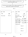
- the mobile phone displays a setting interface 10.
- the setting interface 10 includes a UWB function control and a name of the mobile phone (for example, a device 1), and the user may tap for performing an input on the UWB function control in the setting interface 10, so that the mobile phone enables the UWB function to detect a device by using the UWB function.
- the mobile phone detects another devices, as shown in (B) of FIG.
- the mobile phone may display a name of the detected device (such as a device 2, a device 3, and a device 4) and a plurality of controls (such as a "detected by another device” control, a “coverage range” control, a "distance measurement function” control, an “angle measurement function” control, a “distance measurement precision” control 11, and an “angle measurement precision” control 12) on the setting interface 10. Then, the user may perform the first input on some of the plurality of controls, so that the mobile phone enables privacy settings corresponding to the controls.
- a name of the detected device such as a device 2, a device 3, and a device 4
- a plurality of controls such as a "detected by another device” control, a “coverage range” control, a "distance measurement function” control, an “angle measurement function” control, a “distance measurement precision” control 11, and an “angle measurement precision” control 12
- the user may perform the slide input on the "coverage range” control to set a coverage range of the UWB (for example, 0 to 100 meters, sliding to a leftmost side indicates a minimum set coverage range (namely, 0 meters), and sliding to a rightmost side indicates a maximum set coverage range (namely, 100 meters)) that can be supported by the UWB.
- a user-defined UWB coverage range is displayed to the user in real time, so that a device (namely, the device 1) within the coverage range can detect the mobile phone by using the UWB function, and the mobile phone can detect only the device within the coverage range.
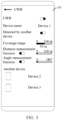
- the user may slide the "coverage range" control to a middle position, that is, a current coverage range of the UWB is 50 meters, so that the mobile phone can detect only a device within the coverage range. For example, a distance between the device 4 and the mobile phone exceeds/is greater than 50 meters, the mobile phone cannot detect the device 4 currently, a name of the device 4 is no longer displayed in the setting interface 10, and the device 4 cannot detect the mobile phone.
- Pr received power
- Pt transmit power
- n is a factor related to a propagation environment
- r is a distance between a transmitting device and a receiving device.
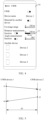
- the first input may include two sub-inputs. Specifically, the user may first tap for performing an input on the "distance measurement function" control, so that the mobile phone enables the distance measurement function, and then the user may perform a slide input on the "distance measurement precision” control 11, so that the mobile phone can adjust the distance measurement precision.
- a distance measurement error value set by the user is added (for example, 0 to 100 meters, sliding to a leftmost side indicates highest set precision (that is, no distance measurement error value is added (in other words, the distance measurement error value is 0 meters), namely, the distance measurement precision of the UWB), and sliding to a rightmost side indicates poorest set precision (for example, it may be set to a maximum distance measurement range (for example, 100 meters) that can be supported by the UWB, that is, the maximum distance measurement range is used as the distance measurement error value)).
- user-defined distance measurement precision is displayed to the user in real time to blur a distance, measured by the another device, between the another device and the electronic device.
- the user may continue to slide the "distance measurement precision” control 11 to a middle position, that is, distance measurement precision/a distance measurement error value is 50 meters.
- a distance d1 between the UWB device 1 and the UWB device 2 may be calculated according to the following formula 1, where c is a speed of light.
- d 1 c ⁇ t 4 ⁇ t 1 ⁇ t 3 ⁇ t 2 2
- the first input may include two sub-inputs. Specifically, the user may first tap for performing an input on the "angle measurement function" control, so that the mobile phone enables the angle measurement function, and then the user may perform a slide input on the "angle measurement precision” control 12, so that the mobile phone can adjust the angle measurement precision.
- the user may tap for performing an input on the "angle measurement function" control, and slide the "angle measurement precision” control 12 to a middle position, that is, the angle measurement precision/angle measurement error value is 90°, so that the mobile phone may send an angle value with an error (such as a sum of a correct angle value measured by the mobile phone and the angle measurement error value) to the another device to achieve a purpose of blurring the angle measurement of the another device.
- an error such as a sum of a correct angle value measured by the mobile phone and the angle measurement error value
- a UWB device receiving a signal needs to have two antennas.
- a principle of angle measurement is shown in FIG. 7 .
- a UWB module of an electronic device (which may be referred to as a UWB master device, hereinafter referred to as a UWB device 1 for short) has two UWB antennas.
- a UWB slave device (which may be referred to as a UWB device 2) sends a signal, time points at which the two antennas of the UWB device 1 receive the signal are t 1 and t 2 respectively.
- the electronic device calculates an angle ⁇ between the UWB device 1 and the UWB device 2 based on a distance k between the two antennas according to the following formula 2.
- the electronic device may locate the another device by using any one of the following two positioning manners.
- the two positioning manners are a positioning manner based on distance measurement and a positioning manner based on distance measurement and angle measurement.
- FIG. 8 is a schematic diagram of the positioning manner based on distance measurement.
- Position coordinates of a UWB device P are (Xp, Yp), and position coordinates of a UWB device A, a UWB device B, and a UWB device C are (Xa, Ya), (Xb, Yb), and (Xc, Yc), respectively.
- a distance between the UWB device A and the UWB device P is r1
- a distance between the UWB device B and the UWB device P is r2
- a distance between the UWB device C and the UWB device P is r3.
- the position coordinates (Xp, Yp) of the UWB device P may be calculated according to the following formula 3.
- Step 202 The electronic device enables a privacy setting corresponding to the target control in response to the first input.
- Step 302 In a case that the distance between the electronic device and the second device is within the target range, the electronic device sends a response signal to the second device.
- the electronic device may send the response signal to the second device, so that the second device can detect the electronic device by using the UWB function (such as distance measurement and angle measurement) after receiving the response signal.
- the UWB function such as distance measurement and angle measurement
- Step 303 In a case that the distance between the electronic device and the second device is outside the target range, the electronic device prohibits sending the response signal to the second device.
- the electronic device may not send the response signal to the second device (in other words, not respond to the signal sent by the second device), so that the second device cannot detect the electronic device by using the UWB function.
- the user may perform the first input on the target control to set a permission of the another device for detecting the electronic device by using the UWB function, so that the electronic device is allowed to be detected only by the device within the target range by using the UWB function, which improves safety of the another device detecting the electronic device via the UWB module.
- the target control is used to set to allow the device within the target range to be detected by using the UWB function.
- the privacy setting method for UWB detection provided in this embodiment of this application further includes the following step 401.
- Step 401 In a case that a target device is detected to be located outside the target range, the electronic device deletes a target device identifier in the first interface.
- the target device identifier is an identifier, in the at least one device identifier, indicating the target device.
- the target control is the second control
- the second control is used to set to allow the device within the target range to be detected by using the UWB function.
- the electronic device may obtain a distance between the target device and the electronic device, to determine, based on the distance, whether the target device is located outside the target range, in other words, whether the distance between the target device and the electronic device is greater than the target range, thereby determining whether to cancel display of the target device identifier.
- an execution order may alternatively be that step 401 is performed before "enabling a privacy setting corresponding to the target control" in step 202, that is, step 401 is performed first, and then "enabling a privacy setting corresponding to the target control" in step 202 is performed.
- step 401 and "enabling a privacy setting corresponding to the target control" in step 202 may be performed at the same time, which is not limited in this embodiment of this application.
- the user may perform the first input on the second control (namely, the "coverage range” control), so that the electronic device is allowed to be detected only by the device within the target range by using the UWB function, and only the device within the target range is detected by using the UWB function, thereby improving safety of the electronic device performing detection via the UWB module, and improving flexibility of the electronic device performing detection via the UWB module.
- the second control namely, the "coverage range” control
- the target control is used to set the distance measurement error value.
- the privacy setting method for UWB detection provided in this embodiment of this application further includes the following step 501 and step 502.
- Step 501 The electronic device determines a target distance and a time error value according to a first formula.
- the foregoing target distance is an actual distance between the electronic device and the first device.
- d is the target distance
- c is a speed of light
- t 1 is a time point at which the first device sends a signal to the electronic device
- t 2 is a time point at which the electronic device receives the signal sent by the first device
- t 3 is a time point at which the electronic device sends a response signal to the first device
- t 4 is a time point at which the first device receives the response signal sent by the electronic device
- D is the distance measurement error value.
- the target control is the third control
- the third control is used to set the distance measurement error value
- a time point at which the UWB device 2 receives a signal of the UWB device 1 is t 2.
- a time point at which the UWB device 1 sends a response signal is t 3
- the UWB device 2 only needs to adjust a value of t 3 or t 2 to reduce a difference by dt, and then a distance (namely, the target distance) between the UWB device 2 and the UWB device 1 can be calculated.
- Step 502 The electronic device determines a first time point and a second time point based on the time error value, and sends the first time point and the second time point to the first device.
- the first time point and the second time point are used for the first device to determine a measurement distance between the first device and the electronic device.
- the first time point is a time point corresponding to t 2
- the second time point is a time point corresponding to t 3.
- the measurement distance is a distance, determined by the first device by using the UWB function, between the first device and the electronic device, and the distance measurement error value is an error value of the measurement distance relative to the target distance.
- the electronic device may add a time value to at least one of t 2 and t 3 (for example, a time error value is added to t 2, and t 3 remains unchanged), to determine the first time point and the second time point.
- the first device calculates the distance between the first device and the electronic device (namely, the measurement distance) according to t 1, the first time point (namely, t 22), the second time point (namely, t 33), and t 4 by using the formula 1.
- the target control is the third control
- the third control is used to set the angle measurement error value.
- the electronic device includes at least two antennas, and the first device includes at least one antenna.
- Step 601 The electronic device determines a target angle value by using the second formula.
- the target angle value is an angle value between the electronic device and the first device.
- ⁇ is the target angle value
- c is a speed of light
- t 1 and t 2 are time points at which the two antennas of the electronic device receive a signal sent by the first device
- k is a distance between the two antennas of the electronic device.
- Step 602 The electronic device sends a second value to the first device.
- the second value is a sum of the target angle value and the angle measurement error value, and the second value is used for the first device to determine the second value as the angle value between the first device and the electronic device.
- the electronic device may accurately calculate the angle value between the electronic device and the first device according to the second formula, and then the electronic device may send the sum (namely, the second value) of the angle value and the set angle measurement error value to the first device, so that the first device may determine the second value as the angle value between the first device and the electronic device, that is, there is an error in the angle value between the first device and the electronic device determined by the first device.
- the angle measurement performed on the electronic device by the first device can be blurred, so that the first device cannot accurately obtain location information of the user, thereby avoiding leakage of user privacy, and improving safety of the electronic device performing angle measurement via the UWB module.
- FIG. 12 is a possible schematic structural diagram of a privacy setting apparatus for UWB detection according to an embodiment of this application.
- the privacy setting apparatus 70 for UWB detection may include a receiving module 71 and an enabling module 72.
- the receiving module 71 is configured to: in a case that a first interface is displayed, receive a first input by a user, where the first interface includes at least one device identifier and at least one control, each device identifier is used to indicate a device that is detected by using a UWB function, each control corresponds to a privacy setting when an electronic device is detected by another device by using the UWB function, and the first input is an input by the user for a target control in the at least one control.
- the enabling module 72 is configured to: in response to the first input received by the receiving module, enable a privacy setting corresponding to the target control.
- the at least one control includes at least one of the following: a first control, a second control, and a third control.
- the first control is used to set whether to allow the electronic device to be detected by the another device by using the UWB function
- the second control is used to set to allow the electronic device to be detected by a device within a target range by using the UWB function
- the third control is used to set a measurement error value between a first device and the electronic device
- the first device is a device for measuring the electronic device.
- the target control is used to set to allow the electronic device to be detected by the device within the target range by using the UWB function.
- the apparatus provided in this embodiment of this application further includes an obtaining module, a sending module, and a prohibiting module.
- the obtaining module is configured to: after the enabling module enables the privacy setting corresponding to the target control, in a case that a signal sent by a second device is received, obtain a distance between the electronic device and the second device.
- the sending module is configured to: in a case that the distance between the electronic device and the second device is within the target range, send a response signal to the second device.
- the prohibiting module is configured to: in a case that the distance between the electronic device and the second device is outside the target range, prohibit sending the response signal to the second device.
- d is the target distance
- c is a speed of light
- t 1 is a time point at which the first device sends a signal to the electronic device
- t 2 is a time point at which the electronic device receives the signal sent by the first device
- t 3 is a time point at which the electronic device sends a response signal to the first device
- t 4 is a time point at which the first device receives the response signal sent by the electronic device
- D is the distance measurement error value.
- the first time point is a time point corresponding to t 2
- the second time point is a time point corresponding to t 3
- the target distance is an actual distance between the electronic device and the first device
- the measurement distance is a distance between the first device and the electronic device determined by the first device by using the UWB function
- the distance measurement error value is an error value of the measurement distance relative to the target distance.
- the target control is used to set an angle measurement error value
- the electronic device includes at least two antennas
- the first device includes at least one antenna.
- the apparatus provided in this embodiment of this application further includes a determining module and a sending module.
- the determining module is configured to: after the enabling module 72 enables the privacy setting corresponding to the target control, determine a target angle value by using a second formula, where the target angle value is an angle value between the electronic device and the first device.
- the sending module is configured to send a second value to the first device, where the second value is a sum of the target angle value and the angle measurement error value, and the second value is used for the first device to determine the second value as the angle value between the first device and the electronic device.
- ⁇ is the target angle value
- c is a speed of light
- t 1 and t 2 are time points at which the two antennas of the electronic device receive a signal sent by the first device
- k is a distance between the two antennas of the electronic device.
- the user may perform the first input on some controls (for example, the target control) in the at least one control (where each control corresponds to the privacy setting when the electronic device is detected by the another device by using the UWB function), to enable a privacy setting corresponding to the control, that is, the user can enable, by user-defining based on a usage requirement, a privacy setting related to detection by using the UWB function, that is, the user can set a related privacy function when the another device detects the electronic device by using the UWB function, to avoid leakage of user privacy, and achieve a purpose of protecting the user privacy, thereby improving safety of performing detection via the UWB module.
- some controls for example, the target control
- each control corresponds to the privacy setting when the electronic device is detected by the another device by using the UWB function
- the non-mobile electronic device may be a server, a network attached storage (Network Attached Storage, NAS), a personal computer (personal computer, PC), a television (television, TV), a teller machine, a self-service machine, or the like. This is not specifically limited in the embodiments of this application.
- the privacy setting apparatus for UWB detection in this embodiment of this application may be an apparatus with an operating system.
- the operating system may be an Android (Android) operating system, may be an iOS operating system, or may be another possible operating system. This is not specifically limited in this embodiment of this application.
- the privacy setting apparatus for UWB detection provided in this embodiment of this application can implement the processes of the foregoing method embodiments, with the same technical effects achieved. To avoid repetition, details are not described herein again.
- an embodiment of this application further provides an electronic device 90, including a processor 91, a memory 92, and a program or an instruction stored in the memory 92 and executable on the processor 91.
- an electronic device 90 including a processor 91, a memory 92, and a program or an instruction stored in the memory 92 and executable on the processor 91.
- the program or the instruction is executed by the processor 91, the processes of the foregoing method embodiments are implemented, with the same technical effects achieved. To avoid repetition, details are not described herein again.
- the electronic device in this embodiment of this application includes the foregoing mobile electronic device and the foregoing non-mobile electronic device.
- FIG. 14 is a schematic diagram of a hardware structure of an electronic device for implementing the embodiments of this application.
- the electronic device 100 includes but is not limited to components such as a radio frequency unit 101, a network module 102, an audio output unit 103, an input unit 104, a sensor 105, a display unit 106, a user input unit 107, an interface unit 108, a memory 109, and a processor 110.
- components such as a radio frequency unit 101, a network module 102, an audio output unit 103, an input unit 104, a sensor 105, a display unit 106, a user input unit 107, an interface unit 108, a memory 109, and a processor 110.
- the electronic device 100 may further include a power supply (such as a battery) for supplying power to the components.
- the power supply may be logically connected to the processor 110 via a power management system. In this way, functions such as charge management, discharge management, and power consumption management are implemented via the power management system.
- a structure of the electronic device shown in FIG. 14 does not constitute a limitation on the electronic device.
- the electronic device may include more or fewer components than those shown in the figure, or a combination of some components, or the components disposed differently. Details are not described herein again.
- the user input unit 107 is configured to: in a case that a first interface is displayed, receive a first input by a user, where the first interface includes at least one device identifier and at least one control, each device identifier is used to indicate a device that is detected by using a UWB function, each control corresponds to a privacy setting when the electronic device is detected by another device by using the UWB function, and the first input is an input by the user for a target control in the at least one control.
- the processor 110 is configured to: in response to the first input, enable a privacy setting corresponding to the target control.
- This embodiment of this application provides the electronic device.
- the user may perform the first input on some controls (for example, the target control) in the at least one control (where each control corresponds to the privacy setting when the electronic device is detected by the another device by using the UWB function), so that the electronic device can enable a privacy setting corresponding to the control, that is, the user can enable, by user-defining based on a usage requirement, a privacy setting related to detection by using the UWB function, that is, the user can set, in the electronic device, a related privacy function when the another device detects the electronic device by using the UWB function, to avoid leakage of user privacy, and achieve a purpose of protecting the user privacy, thereby improving safety of the electronic device performing detection via a UWB module.
- the target control is used to set to allow the electronic device to be detected by a device within a target range by using the UWB function.
- the processor 110 is configured to: after an enabling module enables the privacy setting corresponding to the target control, in a case that a signal sent by a second device is received, obtain a distance between the electronic device and the second device.
- the radio frequency unit 101 is configured to: in a case that the distance between the electronic device and the second device is within the target range, send a response signal to the second device.
- the processor 110 is further configured to: in a case that the distance between the electronic device and the second device is outside the target range, prohibit sending the response signal to the second device.
- the target control is used to set a distance measurement error value.
- the processor 110 is further configured to: after the privacy setting corresponding to the target control is enabled, determine a target distance and a time error value according to a first formula; and determine a first time point and a second time point based on the time error value.
- the radio frequency unit 101 is further configured to send the first time point and the second time point to a first device, where the first time point and the second time point are used for the first device to determine a measurement distance between the first device and the electronic device.
- ⁇ is the target angle value
- c is a speed of light
- t 1 and t 2 are time points at which the two antennas of the electronic device receive a signal sent by the first device
- k is a distance between the two antennas of the electronic device.
- the input unit 104 may include a graphics processing unit (Graphics Processing Unit, GPU) 1041 and a microphone 1042.
- the graphics processing unit 1041 processes image data of a static picture or a video obtained by an image capture apparatus (for example, a camera) in a video capture mode or an image capture mode.
- the display unit 106 may include a display panel 1061, and the display panel 1061 may be configured in a form of a liquid crystal display, an organic light-emitting diode, and the like.
- the user input unit 107 includes a touch panel 1071 and another input device 1072.
- the touch panel 1071 is also referred to as a touchscreen.
- the touch panel 1071 may include two parts: a touch detection apparatus and a touch controller.
- the another input device 1072 may include but is not limited to a physical keyboard, a functional button (such as a volume control button or a power on/off button), a trackball, a mouse, and a joystick, which are not further described herein.
- the memory 109 may be configured to store a software program and various data, including but not limited to an application program and an operating system.
- the processor 110 may be integrated with an application processor and a modem processor.
- the application processor mainly processes an operating system, a user interface, an application program, and the like.
- the modem processor mainly processes wireless communication. It can be understood that the modem processor may alternatively be not integrated in the processor 110.
- An embodiment of this application further provides a readable storage medium.
- the readable storage medium stores a program or an instruction.
- the program or the instruction is executed by a processor, the processes of the foregoing method embodiments are implemented, with the same technical effects achieved. To avoid repetition, details are not described herein again.
- the processor is a processor in the electronic device in the foregoing embodiments.
- the readable storage medium includes a computer-readable storage medium such as a computer read-only memory (Read-Only Memory, ROM), a random access memory (Random Access Memory, RAM), a magnetic disk, or an optical disc.
- An embodiment of this application further provides a chip.
- the chip includes a processor and a communications interface.
- the communications interface is coupled to the processor.
- the processor is configured to run a program or an instruction to implement the processes of the foregoing method embodiments, with the same technical effects achieved. To avoid repetition, details are not described herein again.
- the chip mentioned in this embodiment of this application may also be referred to as a system-level chip, a system chip, a chip system, or a system-on-chip.
- the method in the foregoing embodiments may be implemented by software in combination with a necessary universal hardware platform or by hardware only. In most cases, the former is a preferred implementation.
- the technical solutions of this application essentially or the part contributing to the prior art may be implemented in a form of a software product.
- the computer software product is stored in a storage medium (such as a ROM/RAM, a hard disk, or an optical disc), and includes several instructions for instructing a terminal (which may be a mobile phone, a computer, a server, an air conditioner, a network device, or the like) to perform the methods described in the embodiments of this application.
Landscapes
- Engineering & Computer Science (AREA)
- Radar, Positioning & Navigation (AREA)
- Remote Sensing (AREA)
- Computer Networks & Wireless Communication (AREA)
- Signal Processing (AREA)
- Physics & Mathematics (AREA)
- General Physics & Mathematics (AREA)
- Databases & Information Systems (AREA)
- Computer Security & Cryptography (AREA)
- General Health & Medical Sciences (AREA)
- Bioethics (AREA)
- Health & Medical Sciences (AREA)
- Theoretical Computer Science (AREA)
- General Engineering & Computer Science (AREA)
- Software Systems (AREA)
- Human Computer Interaction (AREA)
- Computer Hardware Design (AREA)
- Medical Informatics (AREA)
- Environmental & Geological Engineering (AREA)
- Telephone Function (AREA)
- Radar Systems Or Details Thereof (AREA)
- Mobile Radio Communication Systems (AREA)
Abstract
Description
- This application claims priority to
Chinese Patent Application No. 202110182230.4, filed in China on February 9, 2021 - This application relates to the field of communication technologies, and specifically, to a privacy setting method and apparatus for UWB detection, and an electronic device.
- At present, when a user uses a social application of an electronic device, some functions in the social application, such as a function of finding nearby friends, a function of sharing a location, may be used to meet a social requirement of the user. Generally, the electronic device can measure a distance between two devices via an ultra-wideband (ultra-wideband, UWB) module integrated in the electronic device, to implement device positioning, device finding, and the like.
- However, when the distance between the devices is measured via the UWB module, because precision of distance measurement via the UWB module can reach a centimeter level, it is easy for another user to perform distance measurement and angle measurement via a plurality of UWB modules to obtain precise location information of the user. As a result, user privacy is leaked, and safety of the electronic device performing detection via the UWB module is poor.
- Embodiments of this application are intended to provide a privacy setting method and apparatus for UWB detection, and an electronic device, which can resolve a problem of poor safety of the electronic device performing detection via a UWB module.
- To resolve the technical problem, this application is implemented as follows.
- According to a first aspect, an embodiment of this application provides a privacy setting method for UWB detection, applied to an electronic device. The privacy setting method for UWB detection includes: in a case that a first interface is displayed, receiving a first input by a user, where the first interface includes at least one device identifier and at least one control, each device identifier is used to indicate a device that is detected by using a UWB function, each control corresponds to a privacy setting when the electronic device is detected by another device by using the UWB function, and the first input is an input by the user for a target control in the at least one control; and in response to the first input, enabling a privacy setting corresponding to the target control.
- According to a second aspect, an embodiment of this application provides a privacy setting apparatus for UWB detection. The privacy setting apparatus for UWB detection includes a receiving module and an enabling module. The receiving module is configured to: in a case that a first interface is displayed, receive a first input by a user, where the first interface includes at least one device identifier and at least one control, each device identifier is used to indicate a device that is detected by using a UWB function, each control corresponds to a privacy setting when an electronic device is detected by another device by using the UWB function, and the first input is an input by the user for a target control in the at least one control. The enabling module is configured to: in response to the first input received by the receiving module, enable a privacy setting corresponding to the target control.
- According to a third aspect, an embodiment of this application provides an electronic device, where the electronic device includes a processor, a memory, and a program or an instruction stored in the memory and executable on the processor, where when the program or the instruction is executed by the processor, the steps of the method according to the first aspect are implemented.
- According to a fourth aspect, an embodiment of this application provides a readable storage medium, where the readable storage medium stores a program or an instruction, and when the program or the instruction is executed by a processor, the steps of the method according to the first aspect are implemented.
- According to a fifth aspect, an embodiment of this application provides a chip, where the chip includes a processor and a communications interface, the communication interface is coupled to the processor, and the processor is configured to run a program or an instruction to implement the method according to the first aspect.
- In the embodiments of this application, in a case that the electronic device detects the another device by using the UWB function, the user may perform the first input on some controls (for example, the target control) in the at least one control (where each control corresponds to the privacy setting when the electronic device is detected by the another device by using the UWB function), so that the electronic device can enable a privacy setting corresponding to the control, that is, the user can enable, by user-defining based on a usage requirement, a privacy setting related to detection by using the UWB function, that is, the user can set, in the electronic device, a related privacy function when the another device detects the electronic device by using the UWB function, to avoid leakage of user privacy, and achieve a purpose of protecting the user privacy, thereby improving safety of the electronic device performing detection via the UWB module.
-
-
FIG. 1 is a first schematic diagram of a privacy setting method for UWB detection according to an embodiment of this application; -
FIG. 2 is a first schematic diagram of an example of an interface of a mobile phone according to an embodiment of this application; -
FIG. 3 is a second schematic diagram of an example of an interface of a mobile phone according to an embodiment of this application; -
FIG. 4 is a third schematic diagram of an example of an interface of a mobile phone according to an embodiment of this application; -
FIG. 5 is a schematic diagram of a principle of distance measurement according to an embodiment of this application; -
FIG. 6 is a fourth schematic diagram of an example of an interface of a mobile phone according to an embodiment of this application; -
FIG. 7 is a schematic diagram of a principle of angle measurement according to an embodiment of this application; -
FIG. 8 is a schematic diagram of a positioning manner based on distance measurement according to an embodiment of this application; -
FIG. 9 is a schematic diagram of a positioning manner based on distance measurement and angle measurement according to an embodiment of this application; -
FIG. 10 is a second schematic diagram of a privacy setting method for UWB detection according to an embodiment of this application; -
FIG. 11 is a third schematic diagram of a privacy setting method for UWB detection according to an embodiment of this application; -
FIG. 12 is a schematic structural diagram of a privacy setting apparatus for UWB detection according to an embodiment of this application; -
FIG. 13 is a first schematic diagram of a hardware structure of an electronic device according to an embodiment of this application; and -
FIG. 14 is a second schematic diagram of a hardware structure of an electronic device according to an embodiment of this application. - The following clearly and completely describes the technical solutions in the embodiments of this application with reference to the accompanying drawings in the embodiments of this application. Apparently, the described embodiments are some rather than all of the embodiments of this application. All other embodiments obtained by a person of ordinary skill in the art based on the embodiments of this application without creative efforts shall fall within the protection scope of this application.
- The terms "first", "second", and the like in the specification and claims of this application are used to distinguish between similar objects rather than to describe a specific order or sequence. It should be understood that the data used in this way is interchangeable in appropriate circumstances so that the embodiments of this application can be implemented in other orders than the order illustrated or described herein, and "first", "second", and the like are usually for distinguishing same-type objects but not limiting the number of objects, for example, a first object may be one or multiple. In addition, in the specification and claims, "and/or" represents at least one of connected objects, and the character "/" generally indicates an "or" relationship between contextually associated objects.
- The following describes in detail a privacy setting method for UWB detection provided in the embodiments of this application by using specific embodiments and application scenarios thereof with reference to the accompanying drawings.
- As a mature communication manner, UWB has been widely used in the field of positioning due to high precision of distance measurement and angle measurement by the UWB. Currently, a plurality of electronic devices perform positioning (such as "finding nearby people" and "seeing nearby friends"), finding items, and the like via an integrated UWB module. A distance between two devices can be measured by the UWB. Depending on power of the UWB, coverage ranges may range from a few meters to hundreds of meters, which is very suitable for near-field social occasions. However, because precision of distance measurement by the UWB can reach a centimeter level, and an angle measurement may be performed in a case of a plurality of antennas, when an electronic device locates another device via a UWB module, it is easy for another user to perform distance measurement and angle measurement by using a UWB device. As a result, precise location information of the electronic device is obtained, which exposes user privacy.
- To resolve the foregoing technical problem, the embodiments of this application propose a privacy protection method for the UWB. In a case that a UWB function is enabled (measurement (such as distance measurement and angle measurement) is performed via the UWB module), the electronic device can display, to the user, a relevant interface for setting the UWB function, so that the user can set, based on a usage requirement of the user, whether to allow the electronic device to be detected by the another device, a coverage range of the UWB (that is, the electronic device is allowed to be detected only by a device within a set coverage range), and precision of the distance measurement and angle measurement (that is, a distance measurement error value and an angle measurement error value are set, so that the anther device cannot accurately obtain the location information of the electronic device). On the premise of meeting a user requirement, location information of the user is blurred to the greatest extent to avoid leakage of the user privacy and protect the user privacy.
- An embodiment of this application provides a privacy setting method for UWB detection.
FIG. 1 is a flowchart of the privacy setting method for UWB detection provided in this embodiment of this application. The method may be applied to an electronic device. As shown inFIG. 1 , the privacy setting method for UWB detection provided in this embodiment of this application may include the followingstep 201 andstep 202. - Step 201: In a case that a first interface is displayed, the electronic device receives a first input by a user.
- In this embodiment of this application, the first interface includes at least one device identifier and at least one control, each device identifier is used to indicate a device that is detected by using a UWB function, each control corresponds to a privacy setting when the electronic device is detected by another device by using the UWB function. The first input is an input by the user for a target control in the at least one control.
- In this embodiment of this application, the user may first enable a UWB function of the electronic device on a setting interface of the electronic device, so that the electronic device can detect the another device by using the UWB function. In a case that the another device is detected, an identifier (such as a device name) of the detected device and a control for the user to set a function related to UWB detection are displayed on the first interface (where the first interface may be a setting interface or an interface after the setting interface is updated). Then, user may perform the first input on some of the controls, so that the electronic device can apply privacy settings corresponding to the controls.
- It should be noted that in a case that the UWB function is disabled, the electronic device cannot detect a device by using the UWB function, and cannot be detected by the another device by using the UWB function. The another device may be another electronic device, or may be another device including a UWB module (or having the UWB function).
- Optionally, in this embodiment of this application, the at least one control includes at least one of the following: a first control, a second control, and a third control. The first control is used to set whether to allow the electronic device to be detected by the another device by using the UWB function, the second control is used to set to allow the electronic device to be detected by a device within a target range by using the UWB function, the third control is used to set a measurement error value between a first device and the electronic device, and the first device is a device for measuring the electronic device.
- It can be understood that a privacy setting corresponding to the first control is that a privacy when the electronic device detects the another device may be set to not allow the another device to detect the electronic device by using the UWB function. A privacy setting corresponding to the second control is that the privacy when the electronic device detects the another device may be set to allow only the device within the target range to detect the electronic device by using the UWB function (in other words, a device located outside the target range cannot detect the electronic device by using the UWB function). A privacy setting corresponding to the third control is that measurement precision/a measurement error value is set when the another device measures the electronic device, to blur a measurement value (such as a distance and an angle value) obtained by the another device measuring the electronic device, that is, there is an error in location information (for example, location information determined by a distance or an angle between the another device and the electronic device) of the electronic device determined by the another device, and therefore the another device cannot accurately locate the electronic device.
- It should be noted that the electronic device may not respond to a detection signal sent by the another device, so that the another device cannot detect the electronic device by using the UWB function.
- Optionally, in this embodiment of this application, the second control is further used to set to allow the device within the target range to be detected by using the UWB function. It can be understood that, the user may not only set, by using the second control, to allow only the device within the target range to detect the electronic device by using the UWB function, but also set to allow only the electronic device to detect the device within the target range by using the UWB function (in other words, the electronic device cannot detect the device outside the target range by using the UWB function).
- Optionally, in this embodiment of this application, the third control is used to set a distance measurement error value/distance measurement precision. Alternatively, the third control is used to set an angle measurement error value/angle measurement precision.
- Optionally, in this embodiment of this application, the first input may be a tap input by the user for the first control. Alternatively, the first input may be a slide input by the user for the second control for adjusting a coverage range (namely, the target range, that is, determining the target range based on a start position and an end position of the slide input) of the UWB. Alternatively, the first input may be a slide input by the user for the third control for adjusting the measurement error value.
- Optionally, in this embodiment of this application, the first interface further includes at least one of the following: a distance measurement control and an angle measurement control, the distance measurement control is used to enable or disable a distance measurement function, and the angle measurement control is used to enable or disable an angle measurement function. The distance measurement function is used to measure a distance between the electronic device and the another device by using the UWB function, and the angle measurement function is used to measure an angle between the electronic device and the another device by using the UWB function.
- It should be noted that, in one manner, the first interface includes at least one device identifier, at least one control (namely, the first control, the second control, and/or the third control), and the measurement control (namely, the distance measurement control and/or the angle measurement control); and in another manner, the first interface includes at least one device identifier and at least one control, and the at least one control includes at least one of the following: the first control, the second control, the third control, the distance measurement control, and the angle measurement control.
- It can be understood that after the user enables the distance measurement function, the electronic device can measure the distance between the electronic device and the another device by using the UWB function. After the distance measurement function is disabled, the electronic device cannot measure the distance between the electronic device and the another device by using the UWB function. Alternatively, after the user enables the angle measurement function, the electronic device can measure an angle value between the electronic device and the another device by using the UWB function. After the angle measurement function is disabled, the electronic device cannot measure the angle value between the electronic device and the another device by using the UWB function. In addition, the electronic device may locate the another device based on the distance between the electronic device and the another device. Alternatively, the electronic device may locate the another device based on the distance between the electronic device and the another device and the angle value between the electronic device and the another device. It should be noted that a specific method for the electronic device locating the another device is described in the following embodiments, and details are not described herein.
- Exemplarily, the following uses an example in which the electronic device is a mobile phone for description. As shown in (A) of
FIG. 2 , the mobile phone displays a settinginterface 10. The settinginterface 10 includes a UWB function control and a name of the mobile phone (for example, a device 1), and the user may tap for performing an input on the UWB function control in the settinginterface 10, so that the mobile phone enables the UWB function to detect a device by using the UWB function. In a case that the mobile phone detects another devices, as shown in (B) ofFIG. 2 , the mobile phone may display a name of the detected device (such as adevice 2, adevice 3, and a device 4) and a plurality of controls (such as a "detected by another device" control, a "coverage range" control, a "distance measurement function" control, an "angle measurement function" control, a "distance measurement precision"control 11, and an "angle measurement precision" control 12) on the settinginterface 10. Then, the user may perform the first input on some of the plurality of controls, so that the mobile phone enables privacy settings corresponding to the controls. - It should be noted that, in one manner, the user may perform the slide input on the "coverage range" control to set a coverage range of the UWB (for example, 0 to 100 meters, sliding to a leftmost side indicates a minimum set coverage range (namely, 0 meters), and sliding to a rightmost side indicates a maximum set coverage range (namely, 100 meters)) that can be supported by the UWB. In addition, a user-defined UWB coverage range is displayed to the user in real time, so that a device (namely, the device 1) within the coverage range can detect the mobile phone by using the UWB function, and the mobile phone can detect only the device within the coverage range. With reference to (B) of
FIG. 2 , as shown inFIG. 3 , the user may slide the "coverage range" control to a middle position, that is, a current coverage range of the UWB is 50 meters, so that the mobile phone can detect only a device within the coverage range. For example, a distance between thedevice 4 and the mobile phone exceeds/is greater than 50 meters, the mobile phone cannot detect thedevice 4 currently, a name of thedevice 4 is no longer displayed in the settinginterface 10, and thedevice 4 cannot detect the mobile phone. - In this embodiment of this application, a setting for the coverage range of the UWB is that in free space, a propagation model of an electromagnetic wave is

- In another manner, the first input may include two sub-inputs. Specifically, the user may first tap for performing an input on the "distance measurement function" control, so that the mobile phone enables the distance measurement function, and then the user may perform a slide input on the "distance measurement precision"
control 11, so that the mobile phone can adjust the distance measurement precision. That is, on the basis of distance measurement precision of the UWB, a distance measurement error value set by the user is added (for example, 0 to 100 meters, sliding to a leftmost side indicates highest set precision (that is, no distance measurement error value is added (in other words, the distance measurement error value is 0 meters), namely, the distance measurement precision of the UWB), and sliding to a rightmost side indicates poorest set precision (for example, it may be set to a maximum distance measurement range (for example, 100 meters) that can be supported by the UWB, that is, the maximum distance measurement range is used as the distance measurement error value)). In addition, user-defined distance measurement precision is displayed to the user in real time to blur a distance, measured by the another device, between the another device and the electronic device. With reference to (B) ofFIG. 2 , as shown inFIG. 4 , after the user taps for performing the input on the "distance measurement function" control, the user may continue to slide the "distance measurement precision"control 11 to a middle position, that is, distance measurement precision/a distance measurement error value is 50 meters. Therefore, the mobile phone can determine a time error value based on the distance measurement error value, and determine two time points (such as a first time point and a second time point described in the following embodiments) based on the time error value to send the two time points to the anther device, so that the another device determines a distance between the another device and the mobile phone (that is, the distance, determined by the another device, between the another device and the mobile phone is a distance with an error from an actual distance) based on the two time points with an error, thereby achieving a purpose of blurring distance measurement of the another device. - In this embodiment of this application, when distance measurement is performed by using the UWB function, a bilateral distance measurement manner may be used. There is no need for performing clock synchronization between UWB modules of devices, and system complexity and costs are very low. A principle of distance measurement is shown in
FIG. 5 . A UWB module (which may be referred to as aUWB device 1 for short) of a device sends a signal at a time point t1. A UWB module (for example, a UWB device 2) of another device receives the signal at a time point t2, and sends a response signal at a time point t3. TheUWB device 1 receives the response signal at a time point t4. A distance d1 between theUWB device 1 and theUWB device 2 may be calculated according to the followingformula 1, where c is a speed of light.
- In still another manner, the first input may include two sub-inputs. Specifically, the user may first tap for performing an input on the "angle measurement function" control, so that the mobile phone enables the angle measurement function, and then the user may perform a slide input on the "angle measurement precision"
control 12, so that the mobile phone can adjust the angle measurement precision. That is, on the basis of angle measurement precision of the UWB, an angle measurement error value set by the user is added (for example, 0° to 180°, sliding to a leftmost side indicates highest set precision (that is, no angle measurement error value is added (in other words, the angle measurement error value is 0°), namely, the angle measurement precision of the UWB), and sliding to a rightmost side indicates poorest set precision (for example, it may be set to a maximum angle measurement range (for example, 180°) that can be supported by the UWB, that is, the maximum angle measurement range is used as the angle measurement error value)). In addition, the user-defined angle measurement precision is displayed to the user in real time to blur an angle value, measured by the another device, between the another device and the electronic device. With reference toFIG. 4 , as shown inFIG. 6 , after setting the angle measurement error value, the user may tap for performing an input on the "angle measurement function" control, and slide the "angle measurement precision"control 12 to a middle position, that is, the angle measurement precision/angle measurement error value is 90°, so that the mobile phone may send an angle value with an error (such as a sum of a correct angle value measured by the mobile phone and the angle measurement error value) to the another device to achieve a purpose of blurring the angle measurement of the another device. - In this embodiment of this application, when angle measurement is performed by using the UWB function, a UWB device receiving a signal needs to have two antennas. A principle of angle measurement is shown in
FIG. 7 . A UWB module of an electronic device (which may be referred to as a UWB master device, hereinafter referred to as aUWB device 1 for short) has two UWB antennas. After another device (which may be referred to as a UWB slave device, hereinafter referred to as a UWB device 2) sends a signal, time points at which the two antennas of theUWB device 1 receive the signal are t1 and t2 respectively. The electronic device calculates an angle θ between theUWB device 1 and theUWB device 2 based on a distance k between the two antennas according to the followingformula 2.
- In this embodiment of this application, after performing distance measurement and/or angle measurement, the electronic device may locate the another device by using any one of the following two positioning manners. The two positioning manners are a positioning manner based on distance measurement and a positioning manner based on distance measurement and angle measurement.
- For example,
FIG. 8 is a schematic diagram of the positioning manner based on distance measurement. Position coordinates of a UWB device P are (Xp, Yp), and position coordinates of a UWB device A, a UWB device B, and a UWB device C are (Xa, Ya), (Xb, Yb), and (Xc, Yc), respectively. A distance between the UWB device A and the UWB device P is r1, a distance between the UWB device B and the UWB device P is r2, and a distance between the UWB device C and the UWB device P is r3. The position coordinates (Xp, Yp) of the UWB device P may be calculated according to the followingformula 3.
- For example,
FIG. 9 is a schematic diagram of the positioning manner based on distance measurement and angle measurement. The position coordinates of the UWB device P are (Xp, Yp), and the position coordinates of the UWB device A are (Xa, Ya). The distance between the UWB device A and the UWB device P is r1 and an angle is θ. The position coordinates (Xp, Yp) of the UWB device P may be calculated by the followingformula 4.
- Step 202: The electronic device enables a privacy setting corresponding to the target control in response to the first input.
- It can be understood that, in a case that the target control is the first control, the electronic device may enable a privacy setting corresponding to the first control, that is, the electronic device is set to be not allowed to be detected by the another device by using the UWB function, to achieve a purpose of protecting user privacy. In a case that the target control is the second control, the electronic device may enable a privacy setting corresponding to the second control, that is, only a device within a range is set to be allowed to detect the electronic device by using the UWB function, thereby achieve the purpose of protecting the user privacy. In a case that the target control is the third control, the electronic device may enable a privacy setting corresponding to the third control, that is, the measurement error value (for example, the distance measurement error value and the angle measurement error value) is set, to blur the measurement performed on the electronic device by the another device. Therefore, the another device cannot accurately obtain location information of the electronic device, thereby achieving the purpose of protecting the user privacy.
- In this embodiment of this application, the user may define whether to allow the electronic device to be detected by the another device, the coverage range of the UWB, the distance measurement precision, the angle measurement precision, and the like, to blur location information of the user to the greatest extent on the premise of meeting various user requirements, avoiding leakage of the user privacy, and improving safety experience.
- According to the privacy setting method for UWB detection provided in this embodiment of this application, in a case that the electronic device detects the another device by using the UWB function, the user may perform the first input on some controls (for example, the target control) in the at least one control (where each control corresponds to the privacy setting when the electronic device is detected by the another device by using the UWB function), so that the electronic device can enable a privacy setting corresponding to the control, that is, the user can enable, by user-defining based on a usage requirement, a privacy setting related to detection by using the UWB function, that is, the user can set, in the electronic device, a related privacy function when the another device detects the electronic device by using the UWB function, to avoid the leakage of the user privacy, and achieve the purpose of protecting the user privacy, thereby improving safety of the electronic device performing detection via the UWB module.
- Optionally, in this embodiment of this application, the target control is used to set to allow the electronic device to be detected by the device within the target range by using the UWB function. After
step 202, the privacy setting method for UWB detection provided in this embodiment of this application further includes the following step 301 to step 303. - Step 301: In a case that a signal sent by a second device is received, the electronic device obtains a distance between the electronic device and the second device.
- It should be noted that, in this manner, the target control is the second control, and the second control is used to set to allow the electronic device to be detected by the device within the target range by using the UWB function.
- Step 302: In a case that the distance between the electronic device and the second device is within the target range, the electronic device sends a response signal to the second device.
- It can be understood that, in a case that the second device is within the target range, the electronic device may send the response signal to the second device, so that the second device can detect the electronic device by using the UWB function (such as distance measurement and angle measurement) after receiving the response signal.
- Step 303: In a case that the distance between the electronic device and the second device is outside the target range, the electronic device prohibits sending the response signal to the second device.
- It can be understood that, in a case that the second device is outside the target range, the electronic device may not send the response signal to the second device (in other words, not respond to the signal sent by the second device), so that the second device cannot detect the electronic device by using the UWB function.
- In this embodiment of this application, the user may perform the first input on the target control to set a permission of the another device for detecting the electronic device by using the UWB function, so that the electronic device is allowed to be detected only by the device within the target range by using the UWB function, which improves safety of the another device detecting the electronic device via the UWB module.
- Optionally, in this embodiment of this application, the target control is used to set to allow the device within the target range to be detected by using the UWB function. After
step 202, the privacy setting method for UWB detection provided in this embodiment of this application further includes the following step 401. - Step 401: In a case that a target device is detected to be located outside the target range, the electronic device deletes a target device identifier in the first interface.
- In this embodiment of this application, the target device identifier is an identifier, in the at least one device identifier, indicating the target device.
- It should be noted that, in this manner, the target control is the second control, and the second control is used to set to allow the device within the target range to be detected by using the UWB function.
- In this embodiment of this application, the electronic device may obtain a distance between the target device and the electronic device, to determine, based on the distance, whether the target device is located outside the target range, in other words, whether the distance between the target device and the electronic device is greater than the target range, thereby determining whether to cancel display of the target device identifier.
- It should be noted that, for step 401, an execution order may alternatively be that step 401 is performed before "enabling a privacy setting corresponding to the target control" in
step 202, that is, step 401 is performed first, and then "enabling a privacy setting corresponding to the target control" instep 202 is performed. Alternatively, step 401 and "enabling a privacy setting corresponding to the target control" instep 202 may be performed at the same time, which is not limited in this embodiment of this application. - In this embodiment of this application, the user may perform the first input on the second control (namely, the "coverage range" control), so that the electronic device is allowed to be detected only by the device within the target range by using the UWB function, and only the device within the target range is detected by using the UWB function, thereby improving safety of the electronic device performing detection via the UWB module, and improving flexibility of the electronic device performing detection via the UWB module.
- Optionally, in this embodiment of this application, the target control is used to set the distance measurement error value. With reference to
FIG. 1 , as shown inFIG, 10 , afterstep 202, the privacy setting method for UWB detection provided in this embodiment of this application further includes the followingstep 501 andstep 502. - Step 501: The electronic device determines a target distance and a time error value according to a first formula.
- In this embodiment of this application, the foregoing target distance is an actual distance between the electronic device and the first device.
- In this embodiment of this application, the first formula is

- It should be noted that, in this manner, the target control is the third control, and the third control is used to set the distance measurement error value.
- In this embodiment of this application, according to the principle of distance measurement in
FIG. 5 , after the user sets the distance measurement error value, a time point at which theUWB device 2 receives a signal of theUWB device 1 is t2. When a time point at which theUWB device 1 sends a response signal is t3, theUWB device 2 only needs to adjust a value of t3 or t2 to reduce a difference by dt, and then a distance (namely, the target distance) between theUWB device 2 and theUWB device 1 can be calculated. Specifically, after a distance measurement error value D is set,
FIG. 5 , and
formula 1, that is, the time error value is
- Step 502: The electronic device determines a first time point and a second time point based on the time error value, and sends the first time point and the second time point to the first device.
- The first time point and the second time point are used for the first device to determine a measurement distance between the first device and the electronic device. The first time point is a time point corresponding to t2 , the second time point is a time point corresponding to t3. The measurement distance is a distance, determined by the first device by using the UWB function, between the first device and the electronic device, and the distance measurement error value is an error value of the measurement distance relative to the target distance.
- It should be noted that, the first time point being the time point corresponding to t2 may be understood as that the electronic device notifies the first device of the time point (where the time point is a time point with a time error) at which the electronic device receives the signal sent by the first device. The second time point being the time point corresponding to t3 may be understood as that the electronic device notifies the first device of the time point (where the time point is a time point with a time error) at which the electronic device sends the response signal to the first device.
- Optionally, in this embodiment of this application, the electronic device may add a time value to at least one of t2 and t3 (for example, a time error value is added to t2, and t3 remains unchanged), to determine the first time point and the second time point.
- It can be understood that t2 and t3 are real time stamps, and the electronic device may calculate an accurate distance (namely, the target distance) from t1 to t4. If the first time point (hereinafter referred to as t22) and the second time point (hereinafter referred to as t33) determined by the electronic device based on the time error value meet the following condition: t33 - t22 = t3 - t2 - dt, there are the following cases.
- In one case, t22 = t2 and t33 = t3 - dt, that is, the sent first time point is a time point not added with the time error value, and the sent second time point is a time point subtracting the time error value.
- In another case, t33 = t3 and t22 = t2 + dt, that is, the sent first time point is a time point added with the time error value, and the sent second time point is a time point not added with the time error value.
- In still another case, t22 = t2 + dt1 and t33 = t3 - dt2, where dt1 + dt2 = dt , that is, the sent first time point is a time point added with the time error value, and the sent second time point is a time point subtracting the time error value.
- In this embodiment of the application, after receiving the first time and the second time, the first device calculates the distance between the first device and the electronic device (namely, the measurement distance) according to t1, the first time point (namely, t22), the second time point (namely, t33), and t4 by using the
formula 1. Specifically, for the foregoing three cases, a measurement distance d2 determined by the first device is
- It can be understood that the electronic device may accurately calculate the distance between the first device and the electronic device according to the first formula, and then the electronic device may determine the time error value based on the distance measurement error value, and determine two time points with errors based on the time error value to send the two time points to the first device, so that the first device may determine the distance between the first device and the electronic device based on the two time points, and therefore there is an error in the distance, determined by the first device, between the first device and the electronic device. In this way, according to this solution, the distance measurement performed on the electronic device by the first device can be blurred, so that the first device cannot accurately obtain location information of the user, thereby avoiding leakage of user privacy, and improving safety of the electronic device performing distance measurement via the UWB module.
- Optionally, in this embodiment of this application, the target control is the third control, and the third control is used to set the angle measurement error value. The electronic device includes at least two antennas, and the first device includes at least one antenna. With reference to
FIG. 1 , as shown inFIG, 11 , afterstep 202, the privacy setting method for UWB detection provided in this embodiment of this application further includes the followingstep 601 andstep 602. - Step 601: The electronic device determines a target angle value by using the second formula.
- In this embodiment of this application, the target angle value is an angle value between the electronic device and the first device.
- In this embodiment of this application, the second formula is

- In this embodiment of this application, according to the principle of angle measurement in
FIG. 7 , after the user sets the angle measurement error value, because a device receiving a UWB signal requires at least two antennas to perform angle measurement, if the UWB slave device has only one antenna, when the UWB slave device sends a signal, the UWB master device has two antennas, the UWB master device can measure an angle value between the UWB master device and the UWB slave device, while the UWB slave device cannot measure the angle value between the UWB slave device and the UWB master device. After the UWB master device measures the angle value between the UWB master device and the UWB slave device, a sum of the angle value and an angle measurement error value set by the user may be sent to the UWB slave device, to blur angle measurement performed on the electronic device by the first device. - Step 602: The electronic device sends a second value to the first device.
- In this embodiment of this application, the second value is a sum of the target angle value and the angle measurement error value, and the second value is used for the first device to determine the second value as the angle value between the first device and the electronic device.
- It can be understood that the electronic device may accurately calculate the angle value between the electronic device and the first device according to the second formula, and then the electronic device may send the sum (namely, the second value) of the angle value and the set angle measurement error value to the first device, so that the first device may determine the second value as the angle value between the first device and the electronic device, that is, there is an error in the angle value between the first device and the electronic device determined by the first device. In this way, according to this solution, the angle measurement performed on the electronic device by the first device can be blurred, so that the first device cannot accurately obtain location information of the user, thereby avoiding leakage of user privacy, and improving safety of the electronic device performing angle measurement via the UWB module.
- It should be noted that the privacy setting method for UWB detection provided in the embodiments of this application may be performed by a privacy setting apparatus for UWB detection or a control module for performing the privacy setting method for UWB detection in the privacy setting apparatus for UWB detection. In the embodiments of this application, the privacy setting apparatus for UWB detection performing the privacy setting method for UWB detection is used as an example to describe the privacy setting apparatus for UWB detection provided in the embodiments of this application.
-
FIG. 12 is a possible schematic structural diagram of a privacy setting apparatus for UWB detection according to an embodiment of this application. As shown inFIG. 12 , theprivacy setting apparatus 70 for UWB detection may include a receivingmodule 71 and an enablingmodule 72. - The receiving
module 71 is configured to: in a case that a first interface is displayed, receive a first input by a user, where the first interface includes at least one device identifier and at least one control, each device identifier is used to indicate a device that is detected by using a UWB function, each control corresponds to a privacy setting when an electronic device is detected by another device by using the UWB function, and the first input is an input by the user for a target control in the at least one control. The enablingmodule 72 is configured to: in response to the first input received by the receiving module, enable a privacy setting corresponding to the target control. - In a possible implementation, the at least one control includes at least one of the following: a first control, a second control, and a third control. The first control is used to set whether to allow the electronic device to be detected by the another device by using the UWB function, the second control is used to set to allow the electronic device to be detected by a device within a target range by using the UWB function, the third control is used to set a measurement error value between a first device and the electronic device, and the first device is a device for measuring the electronic device.
- In a possible implementation, the target control is used to set to allow the electronic device to be detected by the device within the target range by using the UWB function. The apparatus provided in this embodiment of this application further includes an obtaining module, a sending module, and a prohibiting module. The obtaining module is configured to: after the enabling module enables the privacy setting corresponding to the target control, in a case that a signal sent by a second device is received, obtain a distance between the electronic device and the second device. The sending module is configured to: in a case that the distance between the electronic device and the second device is within the target range, send a response signal to the second device. The prohibiting module is configured to: in a case that the distance between the electronic device and the second device is outside the target range, prohibit sending the response signal to the second device.
- In a possible implementation, the target control is used to set to allow the device within the target range to be detected by using the UWB function. The apparatus provided in this embodiment of this application further includes a deletion module. The deletion module is configured to: in a case that a target device is detected to be located outside the target range, delete a target device identifier in the first interface, where the target device identifier is an identifier, in the at least one device identifier, indicating the target device.
- In a possible implementation, the target control is used to set a distance measurement error value. The apparatus provided in this embodiment of this application further includes a determining module and a sending module. The determining module is configured to: after the enabling
module 72 enables the privacy setting corresponding to the target control, determine a target distance and a time error value according to a first formula; and determine a first time point and a second time point based on the time error value. The sending module is configured to send the first time point and the second time point to a first device, where the first time point and the second time point are used for the first device to determine a measurement distance between the first device and the electronic device. - The first formula is

- In a possible implementation, the target control is used to set an angle measurement error value, the electronic device includes at least two antennas, and the first device includes at least one antenna. The apparatus provided in this embodiment of this application further includes a determining module and a sending module. The determining module is configured to: after the enabling
module 72 enables the privacy setting corresponding to the target control, determine a target angle value by using a second formula, where the target angle value is an angle value between the electronic device and the first device. The sending module is configured to send a second value to the first device, where the second value is a sum of the target angle value and the angle measurement error value, and the second value is used for the first device to determine the second value as the angle value between the first device and the electronic device. - The second formula is

- In a possible implementation, the first interface further includes at least one of the following: a distance measurement control and an angle measurement control, the distance measurement control is used to enable or disable a distance measurement function, and the angle measurement control is used to enable or disable an angle measurement function. The distance measurement function is used to measure a distance between the electronic device and the another device by using the UWB function, and the angle measurement function is used to measure an angle between the electronic device and the another device by using the UWB function.
- According to the privacy setting apparatus for UWB detection provided in this embodiment of this application, in a case that the another device is detected by using the UWB function, the user may perform the first input on some controls (for example, the target control) in the at least one control (where each control corresponds to the privacy setting when the electronic device is detected by the another device by using the UWB function), to enable a privacy setting corresponding to the control, that is, the user can enable, by user-defining based on a usage requirement, a privacy setting related to detection by using the UWB function, that is, the user can set a related privacy function when the another device detects the electronic device by using the UWB function, to avoid leakage of user privacy, and achieve a purpose of protecting the user privacy, thereby improving safety of performing detection via the UWB module.
- The privacy setting apparatus for UWB detection in this embodiment of this application may be an apparatus, or may be a component, an integrated circuit, or a chip in a terminal. The apparatus may be a mobile electronic device, or may be a non-mobile electronic device. For example, the mobile electronic device may be a mobile phone, a tablet computer, a notebook computer, a palmtop computer, a vehicle-mounted electronic device, a wearable device, an ultra-mobile personal computer (ultra-mobile personal computer, UMPC), a netbook, a personal digital assistant (personal digital assistant, PDA), or the like. The non-mobile electronic device may be a server, a network attached storage (Network Attached Storage, NAS), a personal computer (personal computer, PC), a television (television, TV), a teller machine, a self-service machine, or the like. This is not specifically limited in the embodiments of this application.
- The privacy setting apparatus for UWB detection in this embodiment of this application may be an apparatus with an operating system. The operating system may be an Android (Android) operating system, may be an iOS operating system, or may be another possible operating system. This is not specifically limited in this embodiment of this application.
- The privacy setting apparatus for UWB detection provided in this embodiment of this application can implement the processes of the foregoing method embodiments, with the same technical effects achieved. To avoid repetition, details are not described herein again.
- Optionally, as shown in
FIG. 13 , an embodiment of this application further provides anelectronic device 90, including aprocessor 91, amemory 92, and a program or an instruction stored in thememory 92 and executable on theprocessor 91. When the program or the instruction is executed by theprocessor 91, the processes of the foregoing method embodiments are implemented, with the same technical effects achieved. To avoid repetition, details are not described herein again. - It should be noted that the electronic device in this embodiment of this application includes the foregoing mobile electronic device and the foregoing non-mobile electronic device.
-
FIG. 14 is a schematic diagram of a hardware structure of an electronic device for implementing the embodiments of this application. - The
electronic device 100 includes but is not limited to components such as aradio frequency unit 101, anetwork module 102, anaudio output unit 103, aninput unit 104, asensor 105, adisplay unit 106, auser input unit 107, aninterface unit 108, amemory 109, and aprocessor 110. - A person skilled in the art can understand that the
electronic device 100 may further include a power supply (such as a battery) for supplying power to the components. The power supply may be logically connected to theprocessor 110 via a power management system. In this way, functions such as charge management, discharge management, and power consumption management are implemented via the power management system. A structure of the electronic device shown inFIG. 14 does not constitute a limitation on the electronic device. The electronic device may include more or fewer components than those shown in the figure, or a combination of some components, or the components disposed differently. Details are not described herein again. - The
user input unit 107 is configured to: in a case that a first interface is displayed, receive a first input by a user, where the first interface includes at least one device identifier and at least one control, each device identifier is used to indicate a device that is detected by using a UWB function, each control corresponds to a privacy setting when the electronic device is detected by another device by using the UWB function, and the first input is an input by the user for a target control in the at least one control. - The
processor 110 is configured to: in response to the first input, enable a privacy setting corresponding to the target control. - This embodiment of this application provides the electronic device. In a case that the electronic device detects the another device by using the UWB function, the user may perform the first input on some controls (for example, the target control) in the at least one control (where each control corresponds to the privacy setting when the electronic device is detected by the another device by using the UWB function), so that the electronic device can enable a privacy setting corresponding to the control, that is, the user can enable, by user-defining based on a usage requirement, a privacy setting related to detection by using the UWB function, that is, the user can set, in the electronic device, a related privacy function when the another device detects the electronic device by using the UWB function, to avoid leakage of user privacy, and achieve a purpose of protecting the user privacy, thereby improving safety of the electronic device performing detection via a UWB module.
- Optionally, in this embodiment of this application, the target control is used to set to allow the electronic device to be detected by a device within a target range by using the UWB function. The
processor 110 is configured to: after an enabling module enables the privacy setting corresponding to the target control, in a case that a signal sent by a second device is received, obtain a distance between the electronic device and the second device. Theradio frequency unit 101 is configured to: in a case that the distance between the electronic device and the second device is within the target range, send a response signal to the second device. Theprocessor 110 is further configured to: in a case that the distance between the electronic device and the second device is outside the target range, prohibit sending the response signal to the second device. - Optionally, in this embodiment of this application, the target control is used to set to allow the device within the target range to be detected by using the UWB function. The
processor 110 is further configured to: in a case that a target device is detected to be located outside the target range, delete a target device identifier in the first interface, where the target device identifier is an identifier, in the at least one device identifier, indicating the target device. - Optionally, in this embodiment of this application, the target control is used to set a distance measurement error value. The
processor 110 is further configured to: after the privacy setting corresponding to the target control is enabled, determine a target distance and a time error value according to a first formula; and determine a first time point and a second time point based on the time error value. Theradio frequency unit 101 is further configured to send the first time point and the second time point to a first device, where the first time point and the second time point are used for the first device to determine a measurement distance between the first device and the electronic device. - The first formula is

- Optionally, in this embodiment of this application, the target control is used to set an angle measurement error value. The electronic device includes at least two antennas, and the first device includes at least one antenna. The
processor 110 is further configured to: after the privacy setting corresponding to the target control is enabled, determine a target angle value by using a second formula, where the target angle value is an angle value between the electronic device and the first device. Theradio frequency unit 101 is configured to send a second value to the first device, where the second value is a sum of the target angle value and the angle measurement error value, and the second value is used for the first device to determine the second value as the angle value between the first device and the electronic device. - The second formula is
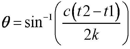
- The electronic device provided in this embodiment of this application can implement the processes of the foregoing method embodiments, with the same technical effects achieved. To avoid repetition, details are not described herein again.
- For the beneficial effects of the implementations in this embodiment, specifically refer to the beneficial effects of the corresponding implementations in the foregoing method embodiments. To avoid repetition, details are not described herein again.
- It should be understood that in this embodiment of this application, the
input unit 104 may include a graphics processing unit (Graphics Processing Unit, GPU) 1041 and amicrophone 1042. Thegraphics processing unit 1041 processes image data of a static picture or a video obtained by an image capture apparatus (for example, a camera) in a video capture mode or an image capture mode. Thedisplay unit 106 may include adisplay panel 1061, and thedisplay panel 1061 may be configured in a form of a liquid crystal display, an organic light-emitting diode, and the like. Theuser input unit 107 includes atouch panel 1071 and anotherinput device 1072. Thetouch panel 1071 is also referred to as a touchscreen. Thetouch panel 1071 may include two parts: a touch detection apparatus and a touch controller. The anotherinput device 1072 may include but is not limited to a physical keyboard, a functional button (such as a volume control button or a power on/off button), a trackball, a mouse, and a joystick, which are not further described herein. Thememory 109 may be configured to store a software program and various data, including but not limited to an application program and an operating system. Theprocessor 110 may be integrated with an application processor and a modem processor. The application processor mainly processes an operating system, a user interface, an application program, and the like. The modem processor mainly processes wireless communication. It can be understood that the modem processor may alternatively be not integrated in theprocessor 110. - An embodiment of this application further provides a readable storage medium. The readable storage medium stores a program or an instruction. When the program or the instruction is executed by a processor, the processes of the foregoing method embodiments are implemented, with the same technical effects achieved. To avoid repetition, details are not described herein again.
- The processor is a processor in the electronic device in the foregoing embodiments. The readable storage medium includes a computer-readable storage medium such as a computer read-only memory (Read-Only Memory, ROM), a random access memory (Random Access Memory, RAM), a magnetic disk, or an optical disc.
- An embodiment of this application further provides a chip. The chip includes a processor and a communications interface. The communications interface is coupled to the processor. The processor is configured to run a program or an instruction to implement the processes of the foregoing method embodiments, with the same technical effects achieved. To avoid repetition, details are not described herein again.
- It should be understood that the chip mentioned in this embodiment of this application may also be referred to as a system-level chip, a system chip, a chip system, or a system-on-chip.
- It should be noted that, in this specification, the terms "include", "comprise", or any of their variants are intended to cover a non-exclusive inclusion, such that a process, a method, an article, or an apparatus that includes a series of elements not only includes those elements but also includes other elements that are not expressly listed, or further includes elements inherent to such process, method, article, or apparatus. In absence of more constraints, an element preceded by "includes a..." does not preclude the existence of other identical elements in the process, method, article, or apparatus that includes the element. In addition, it should be noted that the scope of the method and apparatus in the implementations of this application is not limited to executing functions in the order shown or discussed, but may also include executing the functions in a substantially simultaneous manner or in a reverse order depending on the functions involved. For example, the method described may be performed in an order different from that described, and various steps may be also added, omitted, or combined. In addition, features described with reference to some examples may be combined in other examples.
- According to the foregoing description of the implementations, a person skilled in the art can clearly understand that the method in the foregoing embodiments may be implemented by software in combination with a necessary universal hardware platform or by hardware only. In most cases, the former is a preferred implementation. Based on such an understanding, the technical solutions of this application essentially or the part contributing to the prior art may be implemented in a form of a software product. The computer software product is stored in a storage medium (such as a ROM/RAM, a hard disk, or an optical disc), and includes several instructions for instructing a terminal (which may be a mobile phone, a computer, a server, an air conditioner, a network device, or the like) to perform the methods described in the embodiments of this application.
- The foregoing describes the embodiments of this application with reference to the accompanying drawings. However, this application is not limited to the foregoing specific implementations. The foregoing specific implementations are merely illustrative rather than restrictive. As instructed by this application, a person of ordinary skill in the art may develop many other forms without departing from the principle of this application and the protection scope of the claims, and all such forms fall within the protection scope of this application.
Claims (19)
- A privacy setting method for ultra-wideband UWB detection, applied to an electronic device, wherein the method comprises:in a case that a first interface is displayed, receiving a first input by a user, wherein the first interface comprises at least one device identifier and at least one control, each device identifier is used to indicate a device that is detected by using a UWB function, each control corresponds to a privacy setting when the electronic device is detected by another device by using the UWB function, and the first input is an input by the user for a target control in the at least one control; andin response to the first input, enabling a privacy setting corresponding to the target control.
- The method according to claim 1, wherein the at least one control comprises at least one of the following: a first control, a second control, and a third control; wherein
the first control is used to set whether to allow the electronic device to be detected by the another device by using the UWB function, the second control is used to set to allow the electronic device to be detected by a device within a target range by using the UWB function, the third control is used to set a measurement error value between a first device and the electronic device, and the first device is a device for measuring the electronic device. - The method according to claim 1 or 2, wherein the target control is used to set to allow the electronic device to be detected by a device within a target range by using the UWB function; and
after the privacy setting corresponding to the target control is enabled, the method further comprises:in a case that a signal sent by a second device is received, obtaining a distance between the electronic device and the second device;in a case that the distance between the electronic device and the second device is within the target range, sending a response signal to the second device; andin a case that the distance between the electronic device and the second device is outside the target range, prohibiting sending the response signal to the second device. - The method according to claim 1 or 2, wherein the target control is used to set to allow a device within a target range to be detected by using the UWB function; and the method further comprises:
in a case that a target device is detected to be located outside the target range, deleting a target device identifier in the first interface, wherein the target device identifier is an identifier, in the at least one device identifier, indicating the target device. - The method according to claim 1 or 2, wherein the target control is used to set a distance measurement error value; and
after the privacy setting corresponding to the target control is enabled, the method further comprises:determining a target distance and a time error value according to a first formula; anddetermining a first time point and a second time point based on the time error value, and sending the first time point and the second time point to a first device, wherein the first time point and the second time point are used for the first device to determine a measurement distance between the first device and the electronic device; whereinthe first formula is
- The method according to claim 1 or 2, wherein the target control is used to set an angle measurement error value, the electronic device comprises at least two antennas, and a first device comprises at least one antenna; and
after the privacy setting corresponding to the target control is enabled, the method further comprises:determining a target angle value by using a second formula, wherein the target angle value is an angle value between the electronic device and the first device; andsending a second value to the first device, wherein the second value is a sum of the target angle value and the angle measurement error value, and the second value is used for the first device to determine the second value as the angle value between the first device and the electronic device; whereinthe second formula is
- The method according to claim 1, wherein the first interface further comprises at least one of the following: a distance measurement control and an angle measurement control, the distance measurement control is used to enable or disable a distance measurement function, and the angle measurement control is used to enable or disable an angle measurement function; wherein
the distance measurement function is used to measure a distance between the electronic device and the another device by using the UWB function, and the angle measurement function is used to measure an angle between the electronic device and the another device by using the UWB function. - A privacy setting apparatus for ultra-wideband UWB detection, wherein the apparatus comprises a receiving module and an enabling module, whereinthe receiving module is configured to: in a case that a first interface is displayed, receive a first input by a user, wherein the first interface comprises at least one device identifier and at least one control, each device identifier is used to indicate a device that is detected by using a UWB function, each control corresponds to a privacy setting when an electronic device is detected by another device by using the UWB function, and the first input is an input by the user for a target control in the at least one control; andthe enabling module is configured to: in response to the first input received by the receiving module, enable a privacy setting corresponding to the target control.
- The apparatus according to claim 8, wherein the at least one control comprises at least one of the following: a first control, a second control, and a third control; wherein
the first control is used to set whether to allow the electronic device to be detected by the another device by using the UWB function, the second control is used to set to allow the electronic device to be detected by a device within a target range by using the UWB function, the third control is used to set a measurement error value between a first device and the electronic device, and the first device is a device for measuring the electronic device. - The apparatus according to claim 8 or 9, wherein the target control is used to set to allow the electronic device to be detected by a device within a target range by using the UWB function; andthe apparatus further comprises an obtaining module, a sending module, and a prohibiting module, whereinthe obtaining module is configured to: after the enabling module enables the privacy setting corresponding to the target control, in a case that a signal sent by a second device is received, obtain a distance between the electronic device and the second device;the sending module is configured to: in a case that the distance between the electronic device and the second device is within the target range, send a response signal to the second device; andthe prohibiting module is configured to: in a case that the distance between the electronic device and the second device is outside the target range, prohibit sending the response signal to the second device.
- The apparatus according to claim 8 or 9, wherein the target control is used to set to allow a device within a target range to be detected by using the UWB function; andthe apparatus further comprises a deletion module, whereinthe deletion module is configured to: in a case that a target device is detected to be located outside the target range, delete a target device identifier in the first interface, wherein the target device identifier is an identifier, in the at least one device identifier, indicating the target device.
- The apparatus according to claim 8 or 9, wherein the target control is used to set a distance measurement error value; andthe apparatus further comprises a determining module and a sending module, whereinthe determining module is configured to: after the enabling module enables the privacy setting corresponding to the target control, determine a target distance and a time error value according to a first formula; and determine a first time point and a second time point based on the time error value; andthe sending module is configured to send the first time point and the second time point to a first device, wherein the first time point and the second time point are used for the first device to determine a measurement distance between the first device and the electronic device; whereinthe first formula is

- The apparatus according to claim 8 or 9, wherein the target control is used to set an angle measurement error value, the electronic device comprises at least two antennas, and a first device comprises at least one antenna; andthe apparatus further comprises a determining module and a sending module, whereinthe determining module is configured to: after the enabling module enables the privacy setting corresponding to the target control, determine a target angle value by using a second formula, wherein the target angle value is an angle value between the electronic device and the first device; andthe sending module is configured to send a second value to the first device, wherein the second value is a sum of the target angle value and the angle measurement error value, and the second value is used for the first device to determine the second value as the angle value between the first device and the electronic device; whereinthe second formula is

- The apparatus according to claim 8, wherein the first interface further comprises at least one of the following: a distance measurement control and an angle measurement control, the distance measurement control is used to enable or disable a distance measurement function, and the angle measurement control is used to enable or disable an angle measurement function; wherein
the distance measurement function is used to measure a distance between the electronic device and the another device by using the UWB function, and the angle measurement function is used to measure an angle between the electronic device and the another device by using the UWB function. - An electronic device, comprising a processor, a memory, and a program or an instruction stored in the memory and executable on the processor, wherein when the program or the instruction is executed by the processor, the steps of the privacy setting method for ultra-wideband UWB detection according to any one of claims 1 to 7 are implemented.
- A readable storage medium, wherein the readable storage medium stores a program or an instruction, and when the program or the instruction is executed by a processor, the steps of the privacy setting method for ultra-wideband UWB detection according to any one of claims 1 to 7 are implemented.
- A chip, wherein the chip comprises a processor and a communications interface, the communications interface is coupled to the processor, and the processor is configured to run a program or an instruction to implement the privacy setting method for ultra-wideband UWB detection according to any one of claims 1 to 7.
- A computer program product, wherein the computer program product is executed by at least one processor to implement the privacy setting method for ultra-wideband UWB detection according to any one of claims 1 to 7.
- An electronic device, wherein the electronic device is configured to perform the privacy setting method for ultra-wideband UWB detection according to any one of claims 1 to 7.
Applications Claiming Priority (2)
| Application Number | Priority Date | Filing Date | Title |
|---|---|---|---|
| CN202110182230.4A CN112948873B (en) | 2021-02-09 | 2021-02-09 | Privacy setting method, device and electronic device for UWB detection |
| PCT/CN2022/074042 WO2022170978A1 (en) | 2021-02-09 | 2022-01-26 | Privacy setting method and apparatus for uwb detection, and electronic device |
Publications (3)
| Publication Number | Publication Date |
|---|---|
| EP4293558A1 true EP4293558A1 (en) | 2023-12-20 |
| EP4293558A4 EP4293558A4 (en) | 2024-07-31 |
| EP4293558B1 EP4293558B1 (en) | 2026-03-18 |
Family
ID=76245304
Family Applications (1)
| Application Number | Title | Priority Date | Filing Date |
|---|---|---|---|
| EP22752139.0A Active EP4293558B1 (en) | 2021-02-09 | 2022-01-26 | Privacy setting method and apparatus for uwb detection, and electronic device |
Country Status (4)
| Country | Link |
|---|---|
| US (1) | US12538120B2 (en) |
| EP (1) | EP4293558B1 (en) |
| CN (1) | CN112948873B (en) |
| WO (1) | WO2022170978A1 (en) |
Families Citing this family (3)
| Publication number | Priority date | Publication date | Assignee | Title |
|---|---|---|---|---|
| CN112948873B (en) * | 2021-02-09 | 2024-11-22 | 维沃移动通信有限公司 | Privacy setting method, device and electronic device for UWB detection |
| CN113452601B (en) * | 2021-06-15 | 2023-11-24 | 北京意匠文枢科技有限公司 | A method, device, medium and program product for targeted social networking |
| US12495350B2 (en) * | 2023-02-20 | 2025-12-09 | Nanning Fulian Fugui Precision Industrial Co., Ltd. | Transmission path improving method in a mesh network, electronic device and computer-readable storage medium |
Family Cites Families (23)
| Publication number | Priority date | Publication date | Assignee | Title |
|---|---|---|---|---|
| US20080312946A1 (en) * | 2004-05-03 | 2008-12-18 | Valentine Christopher H | Trade show information management |
| CN101309468A (en) * | 2007-05-16 | 2008-11-19 | 展讯通信(上海)有限公司 | Method and device for determining whether a user is located |
| US11729576B2 (en) * | 2008-03-29 | 2023-08-15 | NEXRF Corp. | Targeted content delivery |
| WO2010001406A1 (en) * | 2008-07-04 | 2010-01-07 | Yogesh Chunilal Bathod | Methods and systems for brands social networks (bsn) platform |
| CN102014337A (en) * | 2010-10-28 | 2011-04-13 | 东莞市泰斗微电子科技有限公司 | Location restriction method as well as corresponding locating device and system |
| US10467580B1 (en) * | 2013-08-12 | 2019-11-05 | United Parcel Service Of America, Inc. | Methods, apparatuses and computer program products for generating logistics zones |
| CN105683774B (en) * | 2014-07-22 | 2018-08-14 | 华为技术有限公司 | Access point, terminal and Wireless Fidelity WiFi indoor orientation methods |
| CN106331035A (en) * | 2015-06-30 | 2017-01-11 | 北京壹人壹本信息科技有限公司 | Tracking prevention method and terminal |
| US11313159B2 (en) * | 2015-09-12 | 2022-04-26 | Adac Plastics, Inc. | Gesture access system for a motor vehicle |
| US9924309B2 (en) * | 2015-12-04 | 2018-03-20 | Yahoo Holdings, Inc. | System and method for mobile device location tracking with a communication event trigger in a wireless network |
| WO2018132647A1 (en) * | 2017-01-13 | 2018-07-19 | Wal-Mart Stores, Inc. | Electronic communications in connection with a package delivery |
| US10212555B1 (en) * | 2017-09-13 | 2019-02-19 | Microsoft Technology Licensing, Llc | Enabling and disabling location sharing based on environmental signals |
| CN108429856A (en) * | 2018-02-28 | 2018-08-21 | 维沃移动通信有限公司 | A kind of location information acquisition methods and mobile terminal |
| US11103773B2 (en) * | 2018-07-27 | 2021-08-31 | Yogesh Rathod | Displaying virtual objects based on recognition of real world object and identification of real world object associated location or geofence |
| WO2020021319A1 (en) * | 2018-07-27 | 2020-01-30 | Yogesh Chunilal Rathod | Augmented reality scanning of real world object or enter into geofence to display virtual objects and displaying real world activities in virtual world having corresponding real world geography |
| US10977927B2 (en) * | 2018-10-24 | 2021-04-13 | Rapidsos, Inc. | Emergency communication flow management and notification system |
| WO2020105759A1 (en) * | 2018-11-23 | 2020-05-28 | 엘지전자 주식회사 | Communication device, control method thereof, and communication system including same |
| US20200272221A1 (en) * | 2019-02-26 | 2020-08-27 | Apple Inc. | Multi-Interface Transponder Device - Power Management |
| KR102818478B1 (en) * | 2019-11-01 | 2025-06-10 | 삼성전자주식회사 | Electronic device and method for performing ranging through uwb |
| CN111125770A (en) * | 2019-12-27 | 2020-05-08 | 维沃移动通信有限公司 | A kind of privacy protection method and electronic device |
| CN112087706B (en) * | 2020-08-05 | 2022-05-10 | 华为技术有限公司 | A position processing method and related equipment |
| CN112261572A (en) * | 2020-10-14 | 2021-01-22 | 北京小米移动软件有限公司 | A method, device and storage medium for information interaction |
| CN112948873B (en) * | 2021-02-09 | 2024-11-22 | 维沃移动通信有限公司 | Privacy setting method, device and electronic device for UWB detection |
-
2021
- 2021-02-09 CN CN202110182230.4A patent/CN112948873B/en active Active
-
2022
- 2022-01-26 WO PCT/CN2022/074042 patent/WO2022170978A1/en not_active Ceased
- 2022-01-26 EP EP22752139.0A patent/EP4293558B1/en active Active
-
2023
- 2023-08-08 US US18/231,776 patent/US12538120B2/en active Active
Also Published As
| Publication number | Publication date |
|---|---|
| US12538120B2 (en) | 2026-01-27 |
| US20230388781A1 (en) | 2023-11-30 |
| WO2022170978A1 (en) | 2022-08-18 |
| EP4293558A4 (en) | 2024-07-31 |
| CN112948873B (en) | 2024-11-22 |
| EP4293558B1 (en) | 2026-03-18 |
| CN112948873A (en) | 2021-06-11 |
Similar Documents
| Publication | Publication Date | Title |
|---|---|---|
| US12538120B2 (en) | Privacy setting method and apparatus for UWB detection, and electronic device | |
| US12369207B2 (en) | Prompt information display method and apparatus and electronic device | |
| EP2851706B1 (en) | Gps positioning method for mobile terminal and mobile terminal | |
| US9313669B2 (en) | Apparatus and method for calculating location of mobile station in wireless network | |
| US9253598B2 (en) | Method for measuring location of terminal in wireless network and device therefor | |
| KR101590918B1 (en) | A method for performing functions of a mobile terminal and a mobile terminal | |
| EP4109218A2 (en) | Mobile phone comprising a touch screen with an in-display fingerprint sensor | |
| EP2824536A1 (en) | Electronic device and method of controlling the same | |
| CN111970639B (en) | Method, device, terminal equipment and storage medium for keeping safe distance | |
| EP2879061A2 (en) | Method and device for enlarging displayed font | |
| CN113687300B (en) | Positioning method and device and electronic equipment | |
| US20170111575A1 (en) | Method and apparatus for adjusting a photo-taking direction, mobile terminal | |
| CN114178720B (en) | Correcting method of galvanometer type laser marking machine and terminal equipment | |
| US20130076644A1 (en) | Spurious input detection system | |
| US20230188995A1 (en) | Integrity protection method and system | |
| US20140120958A1 (en) | Positioning device, mobile station and positioning method | |
| EP4037210A1 (en) | Probe antenna determination method and apparatus | |
| US9125162B2 (en) | Power level adjustment of radio signals in wireless devices | |
| KR102553573B1 (en) | Electronic device and method for detecting touch input of the same | |
| CN110908586A (en) | Keyboard display method and device and terminal equipment | |
| CN112584045A (en) | Positioning display method, terminal and computer readable storage medium | |
| CN111708056A (en) | Signal processing method, processing device and electronic device | |
| CN117768833A (en) | An object-finding guidance method and device | |
| CN115508771A (en) | Method, device, system and storage medium for external calibration of interferometer receiving system | |
| CN111915550B (en) | Image quality detection method, detection apparatus, and storage medium |
Legal Events
| Date | Code | Title | Description |
|---|---|---|---|
| STAA | Information on the status of an ep patent application or granted ep patent |
Free format text: STATUS: THE INTERNATIONAL PUBLICATION HAS BEEN MADE |
|
| PUAI | Public reference made under article 153(3) epc to a published international application that has entered the european phase |
Free format text: ORIGINAL CODE: 0009012 |
|
| STAA | Information on the status of an ep patent application or granted ep patent |
Free format text: STATUS: REQUEST FOR EXAMINATION WAS MADE |
|
| 17P | Request for examination filed |
Effective date: 20230829 |
|
| AK | Designated contracting states |
Kind code of ref document: A1 Designated state(s): AL AT BE BG CH CY CZ DE DK EE ES FI FR GB GR HR HU IE IS IT LI LT LU LV MC MK MT NL NO PL PT RO RS SE SI SK SM TR |
|
| DAV | Request for validation of the european patent (deleted) | ||
| DAX | Request for extension of the european patent (deleted) | ||
| REG | Reference to a national code |
Ref country code: DE Ref legal event code: R079 Free format text: PREVIOUS MAIN CLASS: G06F0021620000 Ipc: H04W0012020000 Ref country code: DE Ref legal event code: R079 Ref document number: 602022032610 Country of ref document: DE Free format text: PREVIOUS MAIN CLASS: G06F0021620000 Ipc: H04W0012020000 |
|
| A4 | Supplementary search report drawn up and despatched |
Effective date: 20240702 |
|
| RIC1 | Information provided on ipc code assigned before grant |
Ipc: G01S 13/87 20060101ALI20240626BHEP Ipc: G01S 13/76 20060101ALI20240626BHEP Ipc: G01S 13/44 20060101ALI20240626BHEP Ipc: G01S 13/02 20060101ALI20240626BHEP Ipc: G01S 5/12 20060101ALI20240626BHEP Ipc: H04W 4/02 20180101ALI20240626BHEP Ipc: H04W 12/02 20090101AFI20240626BHEP |
|
| GRAP | Despatch of communication of intention to grant a patent |
Free format text: ORIGINAL CODE: EPIDOSNIGR1 |
|
| STAA | Information on the status of an ep patent application or granted ep patent |
Free format text: STATUS: GRANT OF PATENT IS INTENDED |
|
| RIC1 | Information provided on ipc code assigned before grant |
Ipc: H04W 12/02 20090101AFI20251015BHEP Ipc: G06F 21/62 20130101ALI20251015BHEP Ipc: G01S 13/87 20060101ALI20251015BHEP Ipc: G01S 13/76 20060101ALI20251015BHEP Ipc: G01S 13/44 20060101ALI20251015BHEP Ipc: G01S 13/02 20060101ALI20251015BHEP Ipc: G01S 5/12 20060101ALI20251015BHEP Ipc: H04W 4/02 20180101ALI20251015BHEP Ipc: H04W 4/80 20180101ALI20251015BHEP Ipc: H04W 8/00 20090101ALI20251015BHEP Ipc: H04W 8/16 20090101ALI20251015BHEP Ipc: H04M 1/72448 20210101ALI20251015BHEP Ipc: H04M 1/72457 20210101ALI20251015BHEP Ipc: H04M 1/72463 20210101ALI20251015BHEP |
|
| INTG | Intention to grant announced |
Effective date: 20251107 |
|
| GRAS | Grant fee paid |
Free format text: ORIGINAL CODE: EPIDOSNIGR3 |
|
| GRAA | (expected) grant |
Free format text: ORIGINAL CODE: 0009210 |
|
| STAA | Information on the status of an ep patent application or granted ep patent |
Free format text: STATUS: THE PATENT HAS BEEN GRANTED |
|
| AK | Designated contracting states |
Kind code of ref document: B1 Designated state(s): AL AT BE BG CH CY CZ DE DK EE ES FI FR GB GR HR HU IE IS IT LI LT LU LV MC MK MT NL NO PL PT RO RS SE SI SK SM TR |
|
| REG | Reference to a national code |
Ref country code: CH Ref legal event code: F10 Free format text: ST27 STATUS EVENT CODE: U-0-0-F10-F00 (AS PROVIDED BY THE NATIONAL OFFICE) Effective date: 20260318 Ref country code: GB Ref legal event code: FG4D |
|
| REG | Reference to a national code |
Ref country code: DE Ref legal event code: R096 Ref document number: 602022032610 Country of ref document: DE |
|
| REG | Reference to a national code |
Ref country code: IE Ref legal event code: FG4D |