EP4293479A1 - Power supply device and display apparatus - Google Patents
Power supply device and display apparatus Download PDFInfo
- Publication number
- EP4293479A1 EP4293479A1 EP23178684.9A EP23178684A EP4293479A1 EP 4293479 A1 EP4293479 A1 EP 4293479A1 EP 23178684 A EP23178684 A EP 23178684A EP 4293479 A1 EP4293479 A1 EP 4293479A1
- Authority
- EP
- European Patent Office
- Prior art keywords
- display apparatus
- saving mode
- condition
- power saving
- unit
- Prior art date
- Legal status (The legal status is an assumption and is not a legal conclusion. Google has not performed a legal analysis and makes no representation as to the accuracy of the status listed.)
- Granted
Links
Images




Classifications
-
- G—PHYSICS
- G06—COMPUTING OR CALCULATING; COUNTING
- G06F—ELECTRIC DIGITAL DATA PROCESSING
- G06F1/00—Details not covered by groups G06F3/00 - G06F13/00 and G06F21/00
- G06F1/26—Power supply means, e.g. regulation thereof
- G06F1/32—Means for saving power
- G06F1/3203—Power management, i.e. event-based initiation of a power-saving mode
- G06F1/3234—Power saving characterised by the action undertaken
- G06F1/3243—Power saving in microcontroller unit
-
- G—PHYSICS
- G06—COMPUTING OR CALCULATING; COUNTING
- G06F—ELECTRIC DIGITAL DATA PROCESSING
- G06F1/00—Details not covered by groups G06F3/00 - G06F13/00 and G06F21/00
- G06F1/26—Power supply means, e.g. regulation thereof
- G06F1/32—Means for saving power
- G06F1/3203—Power management, i.e. event-based initiation of a power-saving mode
- G06F1/3234—Power saving characterised by the action undertaken
- G06F1/325—Power saving in peripheral device
- G06F1/3265—Power saving in display device
-
- G—PHYSICS
- G06—COMPUTING OR CALCULATING; COUNTING
- G06F—ELECTRIC DIGITAL DATA PROCESSING
- G06F1/00—Details not covered by groups G06F3/00 - G06F13/00 and G06F21/00
- G06F1/26—Power supply means, e.g. regulation thereof
- G06F1/32—Means for saving power
- G06F1/3203—Power management, i.e. event-based initiation of a power-saving mode
- G06F1/3206—Monitoring of events, devices or parameters that trigger a change in power modality
- G06F1/3215—Monitoring of peripheral devices
-
- G—PHYSICS
- G06—COMPUTING OR CALCULATING; COUNTING
- G06F—ELECTRIC DIGITAL DATA PROCESSING
- G06F1/00—Details not covered by groups G06F3/00 - G06F13/00 and G06F21/00
- G06F1/26—Power supply means, e.g. regulation thereof
- G06F1/32—Means for saving power
- G06F1/3203—Power management, i.e. event-based initiation of a power-saving mode
- G06F1/3206—Monitoring of events, devices or parameters that trigger a change in power modality
- G06F1/3231—Monitoring the presence, absence or movement of users
Definitions
- a power supply device includes a power supply unit to supply power to an information processing apparatus, an acquisition unit to acquire a detection result of a person by a detection unit disposed at the information processing apparatus, a first determination unit to determine whether a first condition is satisfied and output a first determination result indicating whether the first condition is satisfied, a second determination unit to determine whether a second condition is satisfied and output a second determination result indicating whether the second condition is satisfied, and a control unit to cancel the power saving mode based on the first determination result and the second determination result in a case where the detection result indicates that a person is detected in a state where the information processing apparatus is in the power saving mode.
- the power supplied to the information processing apparatus is reduced as compared with a normal mode.
- the first condition relates to an operation receivable by the information processing apparatus
- the second condition relates to a situation around the information processing apparatus.
- a display apparatus being the information processing apparatus includes the power supply device described above and a display to receive supply of the power from the power supply unit, and the detection unit is disposed at the display.
- the power supply device and the display apparatus that cancel the power saving mode in accordance with the situation to improve usability are provided.
- the display apparatus according to the present embodiment is, for example, an electronic whiteboard to receive, from a user, an input of characters and figures with an electronic pen or the like.
- the display apparatus 2 may be connected to a communication network (not) to communicate with an external device.
- the display apparatus 2 according to the present embodiment includes a display 3 with a touch sensor (an example of a display).
- the display apparatus 2 can receive a stroke drawn by an event input, with an electronic pen 4, to the display 3 having the touch sensor and display an image of the stroke (stroke image) on the display 3 having the touch sensor.
- the event is, for example, an operation such as touching the display 3 with the tip or bottom of the electronic pen 4.
- an image representing characters, shapes, numbers, symbols, lines or a combination thereof that are hand drafted by the user to the display apparatus 2 e.g., electronic whiteboard
- a stroke image an image representing characters, shapes, numbers, symbols, lines or a combination thereof that are hand drafted by the user to the display apparatus 2 (e.g., electronic whiteboard) may be called a "stroke image.”
- the display apparatus 2 may change an image being displayed on the display 3 according to an event (for example, the user's gesture indicating size enlargement, size reduction, or page turning) generated by a user's hand H, in alternative to the electronic pen 4.
- an event for example, the user's gesture indicating size enlargement, size reduction, or page turning
- USB universal serial bus
- PDF portable document format
- the display apparatus 2 includes a connector compatible with a standard such as DisplayPort, Digital Visual Interface (DVI), High-Definition Multimedia Interface (HDMI), and Video Graphics Array (VGA). Therefore, a laptop computer or the like can be connected to the display apparatus 2 via a cable.
- a standard such as DisplayPort, Digital Visual Interface (DVI), High-Definition Multimedia Interface (HDMI), and Video Graphics Array (VGA). Therefore, a laptop computer or the like can be connected to the display apparatus 2 via a cable.
- DVI Digital Visual Interface
- HDMI High-Definition Multimedia Interface
- VGA Video Graphics Array
- the display apparatus 2 further includes a power switch 7 and a human presence sensor 6.
- the power switch 7 is for turning on or off the power of the display apparatus 2.
- the display apparatus 2 can turn on and off in accordance with an input from the user to the power switch 7.
- the display apparatus 2 starts an application program. Thereafter, the display apparatus 2 can perform processing corresponding to the operation input from the user.
- the method that the human presence sensor 6 adopts is not limited to the infrared-based method.
- the human presence sensor 6 may use a face authentication technology to detect whether there is a person in an image taken by a camera, to determine the presence or absence of the person.
- the human presence sensor 6 may detect a person by acquiring sound, temperature, vibration, or a detection result from an external device, or a combination thereof.
- a display apparatus including the power supply device may be any display apparatus not limited to the electronic whiteboard.
- Other examples of the display apparatus 2 include an electronic signboard (digital signage), a telestrator that is used, for example, in sports and weather broadcasts, and a remote image (video) diagnostic apparatus.
- the USB memory 5 is an example of a recording medium connectable to the display apparatus 2.
- the recording medium is not limited thereto.
- the recording medium may be another type of recording medium such as a Secure Digital (SD) card.
- SD Secure Digital
- FIG. 2 is a block diagram illustrating an example of the hardware configuration of the display apparatus 2 according to the present embodiment.
- the display apparatus 2 includes a central processing unit (CPU) 201, a read only memory (ROM) 202, a random access memory (RAM) 203, and a solid state drive (SSD) 204.
- CPU central processing unit
- ROM read only memory
- RAM random access memory
- SSD solid state drive
- the CPU 201 performs an operation in accordance with an input instruction.
- the ROM 202 stores a control program such as an initial program loader (IPL) to boot the CPU 201.
- the RAM 203 is used as a work area for the CPU 201.
- control unit 250 controls the entire display apparatus 2.
- control unit 250 is not limited to that described above, and some or all of the functions of the control unit 250 may be implemented by one or more processing circuits.
- the processing circuit includes an electronic circuit such as the above-described CPU, an application specific integrated circuit (ASIC), and a field programmable gate array (FPGA), and a device such as a conventional circuit module.
- ASIC application specific integrated circuit
- FPGA field programmable gate array
- the SSD 204 stores various data such as an operating system (OS) and a control program for the display apparatus 2, but such data may be stored in the ROM 202.
- the program may be an application program that runs on an information processing apparatus equipped with a general-purpose operating system (OS) such as WINDOWS, MAC OS, ANDROID, and IOS. That is, the display apparatus 2 may be an information processing apparatus.
- OS general-purpose operating system
- the display apparatus 2 includes a network interface (I/F) 205 that controls communication via a communication network, and an external device interface (I/F) 206 that controls communication with an external device such as the USB memory 5 externally attached to the display apparatus 2.
- I/F network interface
- I/F external device interface
- the touch sensor controller 215 includes a communication circuit 215a.
- the communication circuit 215a wirelessly communicates with the electronic pen 4.
- the communication circuit 215a receives a pen ID for identifying the electronic pen 4.
- a commercially available pen can be used as the electronic pen 4.
- One or more electronic pens 4 may be registered in advance in the communication circuit 215a. When the electronic pen 4 is registered, the electronic pen 4 can communicate with the display apparatus 2 without a connection setting operation by the user.
- the method that the touch sensor 214 adopts is not limited to the infrared blocking method.
- the touch sensor 214 may use a capacitive touch panel that identifies the touched position by detecting a change in capacitance.
- the touch sensor 214 may be a resistive-film touch panel that determines the touched position based on a change in voltage of two opposing resistive films.
- the touch sensor 214 may use an electromagnetic induction touch panel, which detects electromagnetic induction caused by contact of an object to a display, to determine the touched position.
- the wireless communication circuit 219 communicates with a communication terminal carried by a user and relays the connection to the Internet, for example.
- the wireless communication circuit 219 performs communication in compliance with WI-FI, BLUETOOTH or the like, but the communications protocols are not limited thereto.
- the wireless communication circuit 219 forms an access point. When a user sets a service set identifier (SSID) and a password that the user obtains in advance to the communication terminal carried by the user, the communication terminal is connected to the access point.
- SSID service set identifier
- the display apparatus 2 further includes a bus line 210.
- the bus line 210 is an address bus or a data bus that electrically connects the elements illustrated in FIG. 3 , such as the CPU 201, to each other.
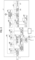
- FIG. 3 is a block diagram illustrating an example of the functions, divided into blocks, of the display apparatus 2 according to the present embodiment.
- the display apparatus 2 functions as an information processing apparatus that executes information processing. Further, the display apparatus 2 functions as a power supply device that controls the consumption of power supplied by the power supply unit 200 implemented by the combination of the power control circuit 224 and one or both of the AC adapter 225 and the battery 226.
- the control unit 250 of the display apparatus 2 includes, for example, an acquisition unit 301, a first determination unit 302, a second determination unit 303, and a mode control unit 304 as functional units implemented by the CPU 201 executing one or more programs installed in the SSD 204.
- the acquisition unit 301 acquires signals from various sensors provided in the display apparatus 2. For example, the acquisition unit 301 acquires a signal indicating a detection result of a person by the human presence sensor 6 (an example of a detection unit) of the display apparatus 2.
- the inactive period T1 (an example of the first length of time) and the inactive period T3 (an example of the third length of time) are time periods during which the human presence sensor 6 does not detect a person.
- the inactive periods T1 and T3 are, for example, periods set in advance by the user and are stored in, for example, the SSD 204. It is desirable that the inactive periods T1 and T3 are set to be equal to or longer than an estimated time for the person who has input the operation to switch to the power saving mode to move out a detection span of the human presence sensor 6 after input of the operation. Simultaneously, the inactive periods T1 and T3 are desirably not too long.
- the inactive periods T1 and T3 are set to about 10 to 60 seconds.
- the optimum value of the inactive periods T1 and T3 differs depending on conditions such as the range in which the human presence sensor 6 detects a person, the location where the display apparatus 2 is installed, and the size of the room where the display apparatus 2 is installed.
- the inactive periods T1 and T3 are set in consideration of the setting of the human presence sensor 6 and the environment where the display apparatus 2 is provided.
- the above-mentioned period of about 10 to 60 seconds is a setting for a general meeting room.
- the second determination unit 303 determines whether or not a second condition is satisfied and outputs a second determination result to the mode control unit 304.
- the second condition is a condition related to a situation around the display apparatus 2 (an example of the information processing apparatus).
- the second determination unit 303 determines that the second condition is satisfied in a case where the number of times of detection of human movement by the human presence sensor 6 per unit time (an example of a second length of time) is greater than a threshold value.
- the second condition is whether the number of times of detection of human movement by the human presence sensor 6 per unit time (an example of the second length of time) is greater than the threshold value, but the second condition is not limited thereto.
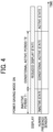
- FIG. 4 is a diagram illustrating state changes of the elements of the display apparatus 2 in the power saving mode.
- the human presence sensor 6 of the display apparatus 2 does not detect a person.
- the display apparatus 2 when the display apparatus 2 is set to the power saving mode (power saving mode is on), the display 3 is in a reduced display state (for example, displaying is off), and the human presence sensor 6 becomes inactive and does not perform the detection for the inactive period T 1.
- conditional active period T2 elapses without detection of a person by the human presence sensor 6, the human presence sensor 6 enters an active state.
- the mode control unit 304 cancels the power saving mode of the display apparatus 2. Note that the conditional active period T2 may be determined according to the actual situation.
- the display 3 enters the reduced display state (for example, displaying is off), and the human presence sensor 6 becomes inactive and does not perform the detection for the inactive period T1.
- the human presence sensor 6 After the inactive period T1 has elapsed, the human presence sensor 6 enters the conditional active state.
- the human presence sensor 6 detects a person at the time t11 at which the human presence sensor 6 is in the conditional active state.
- the power saving mode of the display apparatus 2 is canceled.
- the display apparatus 2 determines that work using the display apparatus 2 is performed since there are many people around the display apparatus 2, and the power saving mode is canceled.
- the second determination unit 303 determines that the number of times of detection by the human presence sensor 6 is equal to or less than the threshold value.
- the mode control unit 304 maintains the power saving mode based on the determination result. Accordingly, the display 3 is kept in the reduced display state (for example, displaying is off).
- the human presence sensor 6 is inactive and does not perform the detection for the inactive period T3 (an example of the third length of time).
- the inactive period T3 may have the same length as the inactive period T1 or may have a different length therefrom.
- the human presence sensor 6 After the inactive period T3 has elapsed, the human presence sensor 6 enters the active state. When the human presence sensor 6 in the active state detects a person, the power saving mode is canceled regardless of the number of detected persons.
- the mode control unit 304 cancels the power saving mode.
- the display 3 enters the normal display state (for example, displaying is on). After the power saving mode is canceled, the human presence sensor 6 becomes inactive and does not perform the detection.
- the display apparatus 2 determines, at the time t21, that the situation when the power saving mode is set continues since there are few people around the display apparatus 2, and the power saving mode is maintained.
- the mode control unit 304 starts switching the display apparatus 2 to the power saving mode (S703).
- the power saving mode for example, the display 3 is turned off, to reduce the power to be supplied.
- the mode control unit 304 sets the human presence sensor 6 to the inactive state (S706).
- the mode control unit 304 sets the human presence sensor 6 to the active state (S712).
- the mode control unit 304 sets the human presence sensor 6 to the inactive state (S716). At this time, the elapsed time is initialized to "0."
- the first condition and the second condition are not limited to the above-described conditions.
- the first determination unit 302 may determine whether or not the first condition is satisfied according to whether or not a predetermined gesture operation is received from the user.
- the power saving mode can be canceled in accordance with the manner in how the user moves, the approaching user can immediately use the display apparatus 2.
- convenience can improve.
- the programs may be recorded in a computer-readable recording medium or carrier medium and distributed.
- the recording medium or carrier medium include, but are not limited to, a magnetic tape, a flash memory, an optical disk, a magnetooptical disk, and a magnetic disk.
- the programs may be distributed through a telecommunication line.
- the display apparatus 2 cancels the power saving mode when the first condition and the second condition are satisfied, thereby improving the convenience of the user using the display apparatus 2.
- the present invention can be implemented in any convenient form, for example using dedicated hardware, or a mixture of dedicated hardware and software.
- the present invention may be implemented as computer software implemented by one or more networked processing apparatuses.
- the processing apparatuses include any suitably programmed apparatuses such as a general purpose computer, a personal digital assistant, a Wireless Application Protocol (WAP) or third-generation (3G)-compliant mobile telephone, and so on. Since the present invention can be implemented as software, each and every aspect of the present invention thus encompasses computer software implementable on a programmable device.
- the computer software can be provided to the programmable device using any conventional carrier medium (carrier means).
- the carrier medium includes a transient carrier medium such as an electrical, optical, microwave, acoustic or radio frequency signal carrying the computer code.
- a power supply device includes a power supply unit to supply power to an information processing apparatus, an acquisition unit to acquire a detection result of a person by a detection unit provided at the information processing apparatus, a first determination unit, a second determination unit, and a control unit.
- the first determination unit determines whether or not a first condition is satisfied and outputs a first determination result.
- the first condition is a condition related to an operation receivable by the information processing apparatus.
- the second determination unit determines whether a second condition is satisfied and outputs a second determination result.
- the second condition is a condition related to a situation around the information processing apparatus.
- a display apparatus includes a display, a power supply unit to supply power to the display, an acquisition unit to acquire a detection result of a person by a detection unit provided at the display, a first determination unit, a second determination unit, and a control unit.
- the first determination unit determines whether or not a first condition is satisfied and outputs a first determination result.
- the first condition is a condition related to an operation receivable by the display apparatus.
- the second determination unit determines that the second condition is not satisfied when the number of times of detection of human movement detected by the detection unit in the second length of time is equal to or less than the threshold value, and the control unit inhibits the detection unit from detecting a human movement for a third length of time.
Landscapes
- Engineering & Computer Science (AREA)
- Theoretical Computer Science (AREA)
- Physics & Mathematics (AREA)
- General Engineering & Computer Science (AREA)
- General Physics & Mathematics (AREA)
- Controls And Circuits For Display Device (AREA)
Abstract
Description
- The present disclosure relates to a power supply device and a display apparatus.
- For power supply devices, there is a technique for changing a method of supplying electric power depending on the situation. For example, there is a device having a normal mode and a power saving mode in which power consumption is reduced as compared with the normal mode.
- For this reason, there is a technique for switching modes based on the result of human detection using a human presence sensor. Relating to the switching modes based on the result of human detection, there are techniques for a display apparatus in a state set to a power saving mode. The technique is for disabling the switching based on the detection result of the human presence sensor for a certain period of time so as to inhibit the power saving mode from being immediately canceled in accordance with the result of human detection. For example,
Japanese Unexamined Patent Application Publication No. 2021-166040 - However, in the technique disclosed in
Japanese Unexamined Patent Application Publication No. 2021-166040 - In view of the foregoing, an object of the present disclosure is to provide a power supply device and a display apparatus that enable canceling a power saving mode in accordance with the surrounding situation.
- In one aspect, a power supply device includes a power supply unit to supply power to an information processing apparatus, an acquisition unit to acquire a detection result of a person by a detection unit disposed at the information processing apparatus, a first determination unit to determine whether a first condition is satisfied and output a first determination result indicating whether the first condition is satisfied, a second determination unit to determine whether a second condition is satisfied and output a second determination result indicating whether the second condition is satisfied, and a control unit to cancel the power saving mode based on the first determination result and the second determination result in a case where the detection result indicates that a person is detected in a state where the information processing apparatus is in the power saving mode. In the power saving mode, the power supplied to the information processing apparatus is reduced as compared with a normal mode. The first condition relates to an operation receivable by the information processing apparatus, and the second condition relates to a situation around the information processing apparatus.
- In another aspect, a display apparatus being the information processing apparatus includes the power supply device described above and a display to receive supply of the power from the power supply unit, and the detection unit is disposed at the display.
- Accordingly, the power supply device and the display apparatus that cancel the power saving mode in accordance with the situation to improve usability are provided.
- A more complete appreciation of embodiments of the present disclosure and many of the attendant advantages and features thereof can be readily obtained and understood from the following detailed description with reference to the accompanying drawings, wherein:
-
FIG. 1 is a diagram illustrating an exterior of a display apparatus according to one embodiment of the present disclosure; -
FIG. 2 is a block diagram illustrating an example of a hardware configuration of the display apparatus according to one embodiment; -
FIG. 3 is a block diagram illustrating an example of functions, divided into blocks, of the display apparatus according to one embodiment; -
FIG. 4 is a diagram illustrating state changes of elements of the display apparatus in a power saving mode, according to one embodiment; -
FIG. 5 is another diagram illustrating state changes of the elements of the display apparatus in the power saving mode, according to one embodiment; -
FIG. 6 is another diagram illustrating state changes of the elements of the display apparatus in the power saving mode, according to one embodiment; and -
FIG. 7 is a flowchart illustrating a sequence of overall operation performed by the display apparatus according to one embodiment. - The accompanying drawings are intended to depict embodiments of the present disclosure and should not be interpreted to limit the scope thereof. The accompanying drawings are not to be considered as drawn to scale unless explicitly noted. Also, identical or similar reference numerals designate identical or similar components throughout the several views.
- In describing embodiments illustrated in the drawings, specific terminology is employed for the sake of clarity. However, the disclosure of this specification is not intended to be limited to the specific terminology so selected and it is to be understood that each specific element includes all technical equivalents that have a similar function, operate in a similar manner, and achieve a similar result.
- Referring now to the drawings, embodiments of the present disclosure are described below. As used herein, the singular forms "a," "an," and "the" are intended to include the plural forms as well, unless the context clearly indicates otherwise.
- Hereinafter, a description is given of a display apparatus having a power supply device according to the present embodiment. The display apparatus according to the present embodiment is, for example, an electronic whiteboard to receive, from a user, an input of characters and figures with an electronic pen or the like.
-
FIG. 1 is a diagram illustrating an exterior of the display apparatus according to the present embodiment. Adisplay apparatus 2 illustrated inFIG. 1 is an example, and a plurality of display apparatuses may be used in combination. - In addition, the
display apparatus 2 may be connected to a communication network (not) to communicate with an external device. Thedisplay apparatus 2 according to the present embodiment includes adisplay 3 with a touch sensor (an example of a display). - Specifically, since the
display apparatus 2 includes thedisplay 3 having the touch sensor, thedisplay apparatus 2 can receive a stroke drawn by an event input, with anelectronic pen 4, to thedisplay 3 having the touch sensor and display an image of the stroke (stroke image) on thedisplay 3 having the touch sensor. The event is, for example, an operation such as touching thedisplay 3 with the tip or bottom of theelectronic pen 4. In this specification, an image representing characters, shapes, numbers, symbols, lines or a combination thereof that are hand drafted by the user to the display apparatus 2 (e.g., electronic whiteboard) may be called a "stroke image." - Further, the
display apparatus 2 may change an image being displayed on thedisplay 3 according to an event (for example, the user's gesture indicating size enlargement, size reduction, or page turning) generated by a user's hand H, in alternative to theelectronic pen 4. - To the
display apparatus 2, a universal serial bus (USB)memory 5 is connectable. When connected to theUSB memory 5, thedisplay apparatus 2 reads an electronic file in a format such as a portable document format (PDF) from theUSB memory 5 or stores an electronic file in theUSB memory 5. - The
display apparatus 2 includes a connector compatible with a standard such as DisplayPort, Digital Visual Interface (DVI), High-Definition Multimedia Interface (HDMI), and Video Graphics Array (VGA). Therefore, a laptop computer or the like can be connected to thedisplay apparatus 2 via a cable. - The
display apparatus 2 further includes apower switch 7 and ahuman presence sensor 6. - The
power switch 7 is for turning on or off the power of thedisplay apparatus 2. Thedisplay apparatus 2 can turn on and off in accordance with an input from the user to thepower switch 7. When the power is turned on, thedisplay apparatus 2 starts an application program. Thereafter, thedisplay apparatus 2 can perform processing corresponding to the operation input from the user. - The
human presence sensor 6 is a sensor that detects the presence or absence of a person. For example, thehuman presence sensor 6 detects a person using infrared rays. That is, infrared rays are emitted depending on the temperature of a human (person) or animal. Thehuman presence sensor 6 detects a person by sensing infrared rays emitted from the person. Thehuman presence sensor 6 according to the present embodiment can detect a plurality of persons present around thedisplay apparatus 2. - The method that the
human presence sensor 6 adopts is not limited to the infrared-based method. For example, thehuman presence sensor 6 may use a face authentication technology to detect whether there is a person in an image taken by a camera, to determine the presence or absence of the person. - Alternatively, the
human presence sensor 6 may detect a person by acquiring sound, temperature, vibration, or a detection result from an external device, or a combination thereof. - In the following, a description is given of an example in which an electronic whiteboard is used as the
display apparatus 2. However, a display apparatus including the power supply device may be any display apparatus not limited to the electronic whiteboard. Other examples of thedisplay apparatus 2 include an electronic signboard (digital signage), a telestrator that is used, for example, in sports and weather broadcasts, and a remote image (video) diagnostic apparatus. - In the description below, the
USB memory 5 is an example of a recording medium connectable to thedisplay apparatus 2. However, the recording medium is not limited thereto. For example, the recording medium may be another type of recording medium such as a Secure Digital (SD) card. - Hereinafter, a description is given of an example of a hardware configuration of the display apparatus according to the present embodiment.
-
FIG. 2 is a block diagram illustrating an example of the hardware configuration of thedisplay apparatus 2 according to the present embodiment. As illustrated inFIG. 2 , thedisplay apparatus 2 includes a central processing unit (CPU) 201, a read only memory (ROM) 202, a random access memory (RAM) 203, and a solid state drive (SSD) 204. - The
CPU 201 performs an operation in accordance with an input instruction. TheROM 202 stores a control program such as an initial program loader (IPL) to boot theCPU 201. TheRAM 203 is used as a work area for theCPU 201. - In the present embodiment, the combination of the
CPU 201, theROM 202, and theRAM 203 implements acontrol unit 250. Thecontrol unit 250 controls theentire display apparatus 2. - Note that, in the present embodiment, the hardware configuration of the
control unit 250 is not limited to that described above, and some or all of the functions of thecontrol unit 250 may be implemented by one or more processing circuits. The processing circuit includes an electronic circuit such as the above-described CPU, an application specific integrated circuit (ASIC), and a field programmable gate array (FPGA), and a device such as a conventional circuit module. - The
SSD 204 stores various data such as an operating system (OS) and a control program for thedisplay apparatus 2, but such data may be stored in theROM 202. The program may be an application program that runs on an information processing apparatus equipped with a general-purpose operating system (OS) such as WINDOWS, MAC OS, ANDROID, and IOS. That is, thedisplay apparatus 2 may be an information processing apparatus. - The
display apparatus 2 includes a network interface (I/F) 205 that controls communication via a communication network, and an external device interface (I/F) 206 that controls communication with an external device such as theUSB memory 5 externally attached to thedisplay apparatus 2. - The
display apparatus 2 further includes thehuman presence sensor 6, thepower switch 7, adisplay controller 213, atouch sensor 214, atouch sensor controller 215, amicrophone 216, aspeaker 217, awireless communication circuit 219, apower control circuit 224, an alternating current (AC)adapter 225, and abattery 226. The configurations of thehuman presence sensor 6 and thepower switch 7 are described above with reference toFIG. 1 . - The
display controller 213 controls screen display for outputting an image to thedisplay 3. - The
touch sensor 214 detects a touch of theelectronic pen 4 or the user's hand H onto thedisplay 3. Theelectronic pen 4 and the user's hand are examples of an input device. - The
touch sensor controller 215 controls processing of thetouch sensor 214. Specifically, thetouch sensor 214 uses an infrared blocking method to detect a touch input onto thedisplay 3 and determine the coordinates to which the touch is input. To detect the touch input and determine the coordinates of the touched position, two light receiving and emitting devices, disposed on both upper side ends of thedisplay 3, emit a plurality of infrared rays in parallel to a surface of thedisplay 3. Then, the emitted infrared rays are reflected by a reflector frame surrounding the sides of thedisplay 3. Light-receiving elements receive light passing an optical path same as the optical path of the emitted infrared rays, which are reflected by the reflector frame. - The
touch sensor 214 outputs an identifier (ID) of the infrared ray that is blocked by an object after being emitted from the two light receiving and emitting devices, to thetouch sensor controller 215. Based on the ID of the infrared ray, thetouch sensor controller 215 detects specific coordinates of the position touched by the object. In the present embodiment, the method of determining the coordinates of the position touched by the object is not limited to the example using two light receiving and emitting devices. Alternatively, for example, the coordinates may be determined using a touch panel. - The
touch sensor controller 215 includes acommunication circuit 215a. Thecommunication circuit 215a wirelessly communicates with theelectronic pen 4. For example, thecommunication circuit 215a receives a pen ID for identifying theelectronic pen 4. For example, when thecommunication circuit 215a performs the communication in compliance with communications protocols such as BLUETOOTH, a commercially available pen can be used as theelectronic pen 4. One or moreelectronic pens 4 may be registered in advance in thecommunication circuit 215a. When theelectronic pen 4 is registered, theelectronic pen 4 can communicate with thedisplay apparatus 2 without a connection setting operation by the user. - The method that the
touch sensor 214 adopts is not limited to the infrared blocking method. For example, thetouch sensor 214 may use a capacitive touch panel that identifies the touched position by detecting a change in capacitance. Thetouch sensor 214 may be a resistive-film touch panel that determines the touched position based on a change in voltage of two opposing resistive films. Alternatively, for example, thetouch sensor 214 may use an electromagnetic induction touch panel, which detects electromagnetic induction caused by contact of an object to a display, to determine the touched position. - The
touch sensor 214 can be of a type that does not require an electronic pen to detect whether a pen tip is in contact with the display. In this case, a fingertip or a pen-shaped stick is used for touch operation. Note that theelectronic pen 4 does not necessarily have an elongated pen shape. - The
microphone 216 is used for inputting sounds. Thespeaker 217 is used for outputting sounds. - The
wireless communication circuit 219 communicates with a communication terminal carried by a user and relays the connection to the Internet, for example. Thewireless communication circuit 219 performs communication in compliance with WI-FI, BLUETOOTH or the like, but the communications protocols are not limited thereto. Thewireless communication circuit 219 forms an access point. When a user sets a service set identifier (SSID) and a password that the user obtains in advance to the communication terminal carried by the user, the communication terminal is connected to the access point. - The
wireless communication circuit 219 may include two or more access points. For example, the following two access points are conceivable.
(a) A first access point to the Internet; and (b) a second access point to an intra-company network to the Internet. - The first access point (a) is for users other than, for example, company staff. The first access point (a) does not allow access from such users to the intra-company network, but allows access to the Internet. On the other hand, the second access point (b) is for intra-company users. The second access point (b) allows the users to access to the intra-company network and the Internet.
- The
power control circuit 224 controls theAC adapter 225 and thebattery 226, which are power supplies for thedisplay apparatus 2. TheAC adapter 225 converts an alternating current supplied by a commercial power supply into a direct current. In the present embodiment, a combination of thepower control circuit 224 and one or both of theAC adapter 225 and thebattery 226 functions as a power supply unit 200 (inFIG. 3 ). For example, thepower control circuit 224 supplies power from theAC adapter 225 or thebattery 226 to theentire display apparatus 2. - In the present embodiment, power is supplied to the
display apparatus 2, but the power supply destination is not limited to thedisplay apparatus 2 but may be any information processing apparatus that consumes the power. - In a case where the
display 3 is a so-called electronic paper, after an image is drawn, thedisplay 3 consumes little or no power to keep displaying the image. In such case, thedisplay apparatus 2 may be driven by thebattery 226. With this structure, thedisplay apparatus 2 is usable as, for example, digital signage used in an outdoor location, where connecting to a power supply is not easy. - The
display apparatus 2 further includes abus line 210. Thebus line 210 is an address bus or a data bus that electrically connects the elements illustrated inFIG. 3 , such as theCPU 201, to each other. - A description is now given of a functional configuration of the
display apparatus 2 according to the present embodiment, with reference toFIG. 3. FIG. 3 is a block diagram illustrating an example of the functions, divided into blocks, of thedisplay apparatus 2 according to the present embodiment. Thedisplay apparatus 2 functions as an information processing apparatus that executes information processing. Further, thedisplay apparatus 2 functions as a power supply device that controls the consumption of power supplied by thepower supply unit 200 implemented by the combination of thepower control circuit 224 and one or both of theAC adapter 225 and thebattery 226. - The
control unit 250 of thedisplay apparatus 2 includes, for example, anacquisition unit 301, afirst determination unit 302, asecond determination unit 303, and amode control unit 304 as functional units implemented by theCPU 201 executing one or more programs installed in theSSD 204. - The
mode control unit 304 controls the mode related to the display apparatus 2 (an example of a control unit). For example, themode control unit 304 switches the mode in which thedisplay apparatus 2 operates. Themode control unit 304 according to the present embodiment can switch the mode by transmitting a signal to thepower control circuit 224. - In addition, the
mode control unit 304 controls thedisplay apparatus 2 in accordance with the currently set mode. - The
display apparatus 2 according to the present embodiment has a normal mode and a power saving mode as switchable modes. - The normal mode is a mode for a normal operation of the
display apparatus 2. - The power saving mode is a mode in which power supplied to the
display apparatus 2 is reduced as compared with the normal mode. In the power saving mode according to the present embodiment, the display of thedisplay 3 is turned off to reduce the power. The power control in the power saving mode is not limited to turning off thedisplay 3 but may be any control to reduce the power consumption. For example, only backlight of thedisplay 3 may be turned off in the power saving mode. The factor for switching between the power saving mode and the normal mode is not limited to whether thedisplay 3 is used. In other words, the power saving mode is a state in which less power is consumed compared with the power consumption in the normal mode. Therefore, aspects of the present disclosure are applicable to any device that performs power control such that the power supply is cut off or reduced in the power saving mode. - For example, the
mode control unit 304 performs the switching from the normal mode to the power saving mode in accordance with, for example, an operation received by thetouch sensor 214 or any of various buttons of thedisplay apparatus 2. The operation received by thetouch sensor 214 is, for example, pressing an icon displayed on thedisplay 3, for switching to the power saving mode. The operation of the various buttons is, for example, pressing a button for turning off thedisplay 3. - The
acquisition unit 301 acquires signals from various sensors provided in thedisplay apparatus 2. For example, theacquisition unit 301 acquires a signal indicating a detection result of a person by the human presence sensor 6 (an example of a detection unit) of thedisplay apparatus 2. - The
first determination unit 302 determines whether or not a first condition is satisfied and outputs a first determination result to themode control unit 304. The first condition is a condition related to an operation receivable by the display apparatus 2 (an example of the information processing apparatus). In the present embodiment, thefirst determination unit 302 determines that the first condition is satisfied in a case where the time starting from the switching of thedisplay apparatus 2 to the power saving mode based on an operation received from the user exceeds an inactive period T1 (seeFIG. 4 , an example of a first length of time). In the example described in the present embodiment, the first condition is whether the predetermined time has elapsed from the reception of the operation for switching to the power saving mode, but the first condition is not limited thereto. The first condition may be, for example, a condition related to an operation from the user. - The
first determination unit 302 according to the present embodiment further determines whether or not the time from the start of time counting exceeds an inactive period T3 (seeFIG. 6 , an example of a third length of time). The trigger for starting the time counting will be described later. - The inactive period T1 (an example of the first length of time) and the inactive period T3 (an example of the third length of time) are time periods during which the
human presence sensor 6 does not detect a person. The inactive periods T1 and T3 are, for example, periods set in advance by the user and are stored in, for example, theSSD 204. It is desirable that the inactive periods T1 and T3 are set to be equal to or longer than an estimated time for the person who has input the operation to switch to the power saving mode to move out a detection span of thehuman presence sensor 6 after input of the operation. Simultaneously, the inactive periods T1 and T3 are desirably not too long. - If the time is shorter than 10 seconds, the person who has input the operation for switching to the power saving mode is likely to be still nearby. When the inactive periods T1 and T3 are set to 10 seconds or greater, the person who has input the operation for switching to the power saving mode can be prevented from being detected again by the
human presence sensor 6 after input of the operation. If the inactive periods T1 and T3 are too long, the next user may not be able to use thedisplay apparatus 2 immediately. Therefore, it is desirable that the inactive periods T1 and T3 are shorter than about 60 seconds. - Accordingly, it is desirable that the inactive periods T1 and T3 are set to about 10 to 60 seconds.
- Such inactive periods T1 and T3 can prevent unwanted detection of the person who has input the operation for switching to the power saving mode while allowing the next user to use the
display apparatus 2 immediately. - However, the optimum value of the inactive periods T1 and T3 differs depending on conditions such as the range in which the
human presence sensor 6 detects a person, the location where thedisplay apparatus 2 is installed, and the size of the room where thedisplay apparatus 2 is installed. Thus, the inactive periods T1 and T3 are set in consideration of the setting of thehuman presence sensor 6 and the environment where thedisplay apparatus 2 is provided. The above-mentioned period of about 10 to 60 seconds is a setting for a general meeting room. - The
second determination unit 303 determines whether or not a second condition is satisfied and outputs a second determination result to themode control unit 304. The second condition is a condition related to a situation around the display apparatus 2 (an example of the information processing apparatus). Thesecond determination unit 303 according to the present embodiment determines that the second condition is satisfied in a case where the number of times of detection of human movement by thehuman presence sensor 6 per unit time (an example of a second length of time) is greater than a threshold value. In the example described in the present embodiment, the second condition is whether the number of times of detection of human movement by thehuman presence sensor 6 per unit time (an example of the second length of time) is greater than the threshold value, but the second condition is not limited thereto. The second condition is, for example, a detection result of a sensor provided in thedisplay apparatus 2 to detect a situation around thedisplay apparatus 2. Note that the unit time (an example of the second length of time) is a time determined for detecting human movement and is determined in accordance with, for example, the performance of thehuman presence sensor 6. - The number of times of detection of human movement by the
human presence sensor 6 may correspond to, for example, the number of persons present around the display apparatus 2 (an example of the information processing apparatus). In other words, the situation where the number of times of detection of human movement is greater than the threshold value is considered to be the situation where the number of persons detected by thehuman presence sensor 6 is greater than the predetermined threshold, and the second condition is satisfied in such a situation. - In a case where the detection result by
human presence sensor 6 indicates the presence of a person after the switching to the power saving mode, themode control unit 304 determines whether or not to cancel the power saving mode based on the first determination result input from thefirst determination unit 302 and the second determination result input from thesecond determination unit 303. - The
mode control unit 304 according to the present embodiment cancels the power saving mode when determining that the first condition is satisfied based on the first determination result and that the second condition is satisfied based on the second determination result. - That is, the
mode control unit 304 cancels the power saving mode when the elapsed time from the switching to the power saving mode exceeds the inactive period T1 (an example of the first length of time) and the number of persons detected by thehuman presence sensor 6 is greater than the threshold value (for example, 2). In the present embodiment, thehuman presence sensor 6 starts the detection after the lapse of the inactive period T1 (an example of the first length of time) from the switching to the power saving mode (after the first condition is determined as being satisfied). Then, themode control unit 304 cancels the power saving mode when the number of persons (the number of movements) detected by thehuman presence sensor 6 is greater than the threshold value (for example, 2). - Next, a description is given of a first example of the control performed in the
display apparatus 2 in the power saving mode.FIG. 4 is a diagram illustrating state changes of the elements of thedisplay apparatus 2 in the power saving mode. In the example illustrated inFIG. 4 , thehuman presence sensor 6 of thedisplay apparatus 2 does not detect a person. - As illustrated in
FIG. 4 , when thedisplay apparatus 2 is set to the power saving mode (power saving mode is on), thedisplay 3 is in a reduced display state (for example, displaying is off), and thehuman presence sensor 6 becomes inactive and does not perform the detection for the inactive period T 1. - After the inactive period T1 has elapsed, the
human presence sensor 6 enters a conditional active state for a conditional active period T2. A description of a case where a person is detected in the conditional active state is deferred. - When the conditional active period T2 elapses without detection of a person by the
human presence sensor 6, thehuman presence sensor 6 enters an active state. When thehuman presence sensor 6 in the active state detects a person, themode control unit 304 cancels the power saving mode of thedisplay apparatus 2. Note that the conditional active period T2 may be determined according to the actual situation. - Next, a description is given of a second example of the control performed in the
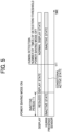
display apparatus 2 in the power saving mode.FIG. 5 is another diagram illustrating state changes of the elements of thedisplay apparatus 2 in the power saving mode. In the example illustrated inFIG. 5 , thehuman presence sensor 6 of thedisplay apparatus 2 detects a person at a time 111. - First, as in
FIG. 4 , when thedisplay apparatus 2 is set to the power saving mode, thedisplay 3 enters the reduced display state (for example, displaying is off), and thehuman presence sensor 6 becomes inactive and does not perform the detection for the inactive period T1. - After the inactive period T1 has elapsed, the
human presence sensor 6 enters the conditional active state. Thehuman presence sensor 6 detects a person at the time t11 at which thehuman presence sensor 6 is in the conditional active state. - In the example illustrated in
FIG. 5 , at the time t11, thesecond determination unit 303 determines that the number of times of detection (the number of persons detected) by thehuman presence sensor 6 is greater than the threshold value. In this case, themode control unit 304 cancels the power saving mode based on the determination result. As a result, thedisplay 3 enters a normal display state (for example, displaying is on). After the power saving mode is canceled, thehuman presence sensor 6 becomes inactive and does not perform the detection. - In the example illustrated in
FIG. 5 , while thehuman presence sensor 6 is in the conditional active state, the number of times of detection by thehuman presence sensor 6, in other words, the number of detected persons, is greater than the threshold value. In such a case, the power saving mode of thedisplay apparatus 2 is canceled. In other words, thedisplay apparatus 2 determines that work using thedisplay apparatus 2 is performed since there are many people around thedisplay apparatus 2, and the power saving mode is canceled. - Next, a description is given of a third example of the control performed in the
display apparatus 2 in the power saving mode.FIG. 6 is another diagram illustrating state changes of the elements of thedisplay apparatus 2 in the power saving mode. In the example illustrated inFIG. 6 , thehuman presence sensor 6 of thedisplay apparatus 2 detects a person at a time t21. - First, as in
FIG. 4 , when thedisplay apparatus 2 is set to the power saving mode, thedisplay 3 enters the reduced display state (for example, displaying is off), and thehuman presence sensor 6 becomes inactive and does not perform the detection for the inactive period T1. - After the inactive period T1 has elapsed, the
human presence sensor 6 enters the conditional active state. Thehuman presence sensor 6 detects a person at the time t21 at which thehuman presence sensor 6 is in the conditional active state. - In the example illustrated in
FIG. 6 , thesecond determination unit 303 determines that the number of times of detection by thehuman presence sensor 6 is equal to or less than the threshold value. In this case, themode control unit 304 maintains the power saving mode based on the determination result. Accordingly, thedisplay 3 is kept in the reduced display state (for example, displaying is off). Thehuman presence sensor 6 is inactive and does not perform the detection for the inactive period T3 (an example of the third length of time). The inactive period T3 may have the same length as the inactive period T1 or may have a different length therefrom. - After the inactive period T3 has elapsed, the
human presence sensor 6 enters the active state. When thehuman presence sensor 6 in the active state detects a person, the power saving mode is canceled regardless of the number of detected persons. - In the example illustrated in
FIG. 6 , since thehuman presence sensor 6 detects a person at the time t22, themode control unit 304 cancels the power saving mode. As a result, thedisplay 3 enters the normal display state (for example, displaying is on). After the power saving mode is canceled, thehuman presence sensor 6 becomes inactive and does not perform the detection. - In the example illustrated in
FIG. 6 , while thehuman presence sensor 6 is in the conditional active state, at the time t21, the number of times of detection by thehuman presence sensor 6, in other words, the number of detected persons, is equal to or less than the threshold value. In such a case, thedisplay apparatus 2 is kept in the power saving mode, and thehuman presence sensor 6 becomes inactive again. In other words, thedisplay apparatus 2 determines, at the time t21, that the situation when the power saving mode is set continues since there are few people around thedisplay apparatus 2, and the power saving mode is maintained. - A description is given below of a sequence of overall operation performed by the
display apparatus 2 according to the present embodiment. -
FIG. 7 is a flowchart illustrating the sequence of overall operation performed by thedisplay apparatus 2 according to the present embodiment. In the example illustrated inFIG. 7 , thedisplay apparatus 2 has already been turned on. - First, the
mode control unit 304 performs the control of thedisplay apparatus 2 in the normal mode (S701). For example, the normal mode is set when the person (user) is using thedisplay apparatus 2 at a meeting or the like. - Then, the
mode control unit 304 receives an operation for switching to the power saving mode from, for example, the touch sensor 214 (S702). For example, the operation for switching to the power saving mode to turn thedisplay 3 off is received via an interface such as a button or an icon. - Then, the
mode control unit 304 proceeds to the S703 triggered by the operation. - The
mode control unit 304 starts switching thedisplay apparatus 2 to the power saving mode (S703). In the power saving mode, for example, thedisplay 3 is turned off, to reduce the power to be supplied. - The
mode control unit 304 starts counting the elapsed time (S704). - The
mode control unit 304 checks whether or not thedisplay apparatus 2 has switched to the power saving mode (for example, whether or not thedisplay 3 has been turned off) (S705). When thedisplay apparatus 2 has not switched to the power saving mode (S705: NO), themode control unit 304 repeatedly checks the mode switching. - On the other hand, when determining that the
display apparatus 2 has switched to the power saving mode (S705: YES), themode control unit 304 sets thehuman presence sensor 6 to the inactive state (S706). - Thereafter, the
first determination unit 302 determines whether or not the elapsed time has exceeded the inactive period T1 (S707). When determining that the elapsed time has not exceeded the inactive period T1 (S707: NO), thefirst determination unit 302 performs the determination of S707 again. - When determining that the elapsed time has exceeded the inactive period T1 (S707: YES), the
first determination unit 302 outputs the determination result to themode control unit 304. Themode control unit 304 sets thehuman presence sensor 6 to the conditional active state (S708). - Further, the
mode control unit 304 initializes the elapsed time to "0" and then starts counting the elapsed time again (S709). - Then, the
mode control unit 304 determines whether thehuman presence sensor 6 has detected a person based on the detection result acquired by the acquisition unit 301 (S710). If it is determined that a person has not been detected (S710: NO), thefirst determination unit 302 determines whether or not the elapsed time has exceeded the conditional active period T2 (S711). When the determination result is that the conditional active period T2 has not elapsed (S711: NO), the determination in S710 is performed again. - On the other hand, in a case where the
first determination unit 302 determines that the elapsed time has exceeded the conditional active period T2 (S711: YES), the determination result is output to themode control unit 304. Accordingly, themode control unit 304 sets thehuman presence sensor 6 to the active state (S712). - Then, the
mode control unit 304 determines whether thehuman presence sensor 6 has detected a person based on the detection result acquired by the acquisition unit 301 (S713). When it is determined that a person is not detected (S713: NO), the determination is repeated until a person is detected. - On the other hand, when determining that the
human presence sensor 6 has detected a person (S713: YES) based on the signal from thehuman presence sensor 6, indicating that a person has been detected, themode control unit 304 cancels the power saving mode and ends the process (S715). - When it is determined that the
human presence sensor 6 has detected a person in the S710 (S710: YES), thesecond determination unit 303 determines whether or not the number of times of detection is greater than the threshold value (S714). - When the
second determination unit 303 determines that the number of times of detection is greater than the threshold value (S714: YES), themode control unit 304 cancels the power saving mode and ends the process (S715). - On the other hand, when the
second determination unit 303 determines that the number of times of detection is equal to or less than the threshold value (S714: NO), themode control unit 304 sets thehuman presence sensor 6 to the inactive state (S716). At this time, the elapsed time is initialized to "0." - Thereafter, the
first determination unit 302 determines whether or not the elapsed time has exceeded the inactive period T3 (S717). When determining that the elapsed time does not exceed the inactive period T3 (S717: NO), thefirst determination unit 302 repeats the determination until the elapsed time exceeds the inactive period T3. - On the other hand, when determining that the elapsed time has exceeded the inactive period T3 (S717: YES), the
first determination unit 302 outputs the determination result to themode control unit 304. Accordingly, themode control unit 304 sets thehuman presence sensor 6 to the active state (S712). Since the subsequent process (S713 and S715) is as described above, the descriptions thereof are omitted. - A description is given of a modification of the above-described embodiment.
- In the above-described embodiment, the first condition and the second condition are not limited to the above-described conditions. For example, regarding the first condition, the
first determination unit 302 may determine whether or not the first condition is satisfied according to whether or not a predetermined gesture operation is received from the user. - For example, face authentication may be used to determine whether the condition is satisfied. For example, when the
display apparatus 2 includes a sensor that performs face authentication, a user who performs an operation to set thedisplay apparatus 2 to the power saving mode can be recognized. Then, thesecond determination unit 303 may determine that the second condition is satisfied when determining that the detection result of the face authentication indicates the detection of a user different from the user recognized at the reception of the operation. The first condition in this case may be the same as or different from that in the above-described embodiment. - The user who performs the operation for switching to the power saving mode is often the person who had finished using the
display apparatus 2. Therefore, when a user different from the user who has performed the operation is detected, it can be determined that the different user is about to use thedisplay apparatus 2 next. Therefore, thesecond determination unit 303 may determine that the second condition is satisfied when determining that the different user is detected. - Any other user recognition technique may be used, such as a user recognition technique based on an ID of the user.
- Regarding the second condition, a user approaching the
display apparatus 2 may be detected. For example, thesecond determination unit 303 determines whether or not there is an approaching user based on a detection result input from a sensor that measures a distance to the user. That is, it can be determined that the user who is going away has finished using thedisplay apparatus 2, and the user who is approaching is about to start using thedisplay apparatus 2. Therefore, thesecond determination unit 303 may determine that the second condition is satisfied when determining that there is an approaching user based on the detection result. - In the present modification, since the power saving mode can be canceled in accordance with the manner in how the user moves, the approaching user can immediately use the
display apparatus 2. Thus, convenience can improve. - Examples of the operation mode are not limited to the two modes, namely, the normal mode and the power saving mode. The apparatus incorporating the power supply device may operate in various modes, as long as the power saving mode can be set. Further, the name of the mode may be other than the normal mode or the power saving mode. For example, the power saving mode may be a mode, such a mode called "standby mode," in which the power consumption is smaller than the mode in which the apparatus is used.
- The above-described embodiment concerns the example in which the switching to the power saving mode is performed based on the operation received from the user. However, the manner of switching to the power saving mode is not limited to the manner based on the operation received from the user. For example, the
display apparatus 2 may be set to enter the power saving mode at the activation of thedisplay apparatus 2, may be switched to the power saving mode after the elapse of a predetermined time from the reception of an operation from the user, or may be switched to the power saving mode after the elapse of a predetermined time counted by a timer. - All or a part of the processing described in this disclosure may be performed by a computer operating according to a program for causing the computer to execute a method for controlling power supply. Specifically, the program is a computer program for causing a processor incorporated in, for example, a power supply device or a display apparatus, to execute the processes for controlling power supply. Therefore, in execution of the program for controlling power supply, the computer having a processor and a control circuit performs calculations and control operations according to the program to carry out the method for controlling power supply.
- A storage device included in the computer stores data used in the processes according to the program so that the computer executes the processes.
- The programs may be recorded in a computer-readable recording medium or carrier medium and distributed. Note that examples of the recording medium or carrier medium include, but are not limited to, a magnetic tape, a flash memory, an optical disk, a magnetooptical disk, and a magnetic disk. The programs may be distributed through a telecommunication line.
- Although several examples of the embodiments of the present invention have been described above, embodiments of the present invention are not limited to the above-described embodiments. That is, various modifications and improvements can be made within the scope of the present invention.
- In the embodiment and the modification described above, the
display apparatus 2 cancels the power saving mode when the first condition and the second condition are satisfied, thereby improving the convenience of the user using thedisplay apparatus 2. - The above-described embodiments are illustrative and do not limit the present invention. Any one of the above-described operations may be performed in various other ways, for example, in an order different from the one described above.
- The present invention can be implemented in any convenient form, for example using dedicated hardware, or a mixture of dedicated hardware and software. The present invention may be implemented as computer software implemented by one or more networked processing apparatuses. The processing apparatuses include any suitably programmed apparatuses such as a general purpose computer, a personal digital assistant, a Wireless Application Protocol (WAP) or third-generation (3G)-compliant mobile telephone, and so on. Since the present invention can be implemented as software, each and every aspect of the present invention thus encompasses computer software implementable on a programmable device. The computer software can be provided to the programmable device using any conventional carrier medium (carrier means). The carrier medium includes a transient carrier medium such as an electrical, optical, microwave, acoustic or radio frequency signal carrying the computer code. An example of such a transient medium is a Transmission Control Protocol/Internet Protocol (TCP/IP) signal carrying computer code over an IP network, such as the Internet. The carrier medium may also include a storage medium for storing processor readable code such as a floppy disk, a hard disk, a compact disc read-only memory (CD-ROM), a magnetic tape device, or a solid state memory device.
- Aspects of the present disclosure are, for example, as follows.
- According to Aspect 1, a power supply device includes a power supply unit to supply power to an information processing apparatus, an acquisition unit to acquire a detection result of a person by a detection unit provided at the information processing apparatus, a first determination unit, a second determination unit, and a control unit. The first determination unit determines whether or not a first condition is satisfied and outputs a first determination result. The first condition is a condition related to an operation receivable by the information processing apparatus. The second determination unit determines whether a second condition is satisfied and outputs a second determination result. The second condition is a condition related to a situation around the information processing apparatus.
- In a case where the detection result indicates that a person is detected in a state where the information processing apparatus is in a power saving mode in which the power supplied to the information processing apparatus is reduced as compared with a normal mode, the control unit cancels the power saving mode based on the first determination result and the second determination result.
- According to
Aspect 2, in the power supply device of Aspect 1, the first determination unit determines that the first condition is satisfied when an elapsed time from switching to the power saving mode exceeds a first length of time. - According to
Aspect 3, in the power supply device ofAspect 1 or 2, the second determination unit determines that the second condition is satisfied when the number of times of detection of human movement detected by the detection unit in a second length of time is greater than a threshold value. - According to
Aspect 4, in the power supply device of any one of Aspects 1 to 3, the second determination unit determines that the second condition is not satisfied when the number of times of detection of human movement detected by the detection unit in the second length of time is equal to or less than the threshold value, and the control unit inhibits the detection unit from detecting a human movement for a third length of time. - According to
Aspect 5, a display apparatus includes a display, a power supply unit to supply power to the display, an acquisition unit to acquire a detection result of a person by a detection unit provided at the display, a first determination unit, a second determination unit, and a control unit. The first determination unit determines whether or not a first condition is satisfied and outputs a first determination result. The first condition is a condition related to an operation receivable by the display apparatus. - The second determination unit determines whether a second condition is satisfied and outputs a second determination result. The second condition is a condition related to a situation around the display apparatus.
- In a case where the detection result indicates that a person is detected in a state where the display apparatus is in a power saving mode in which the power supplied to the display is reduced as compared with a normal mode, the control unit cancels the power saving mode based on the first determination result and the second determination result.
- According to
Aspect 6, in the display apparatus ofAspect 5, the first determination unit determines that the first condition is satisfied when an elapsed time from switching to the power saving mode exceeds a first length of time. - According to
Aspect 7, in the display apparatus ofAspect - According to Aspect 8, in the display apparatus of any one of
Aspect 5 to 7, the second determination unit determines that the second condition is not satisfied when the number of times of detection of human movement detected by the detection unit in the second length of time is equal to or less than the threshold value, and the control unit inhibits the detection unit from detecting a human movement for a third length of time.
Claims (5)
- A power supply device comprising:a power supply unit (200) configured to supply power to an information processing apparatus;an acquisition unit (301) configured to acquire a detection result of a person by a detection unit (6) disposed at the information processing apparatus;a first determination unit (302) configured to output a first determination result indicating whether a first condition is satisfied, the first condition being related to an operation receivable by the information processing apparatus;a second determination unit (303) configured to output a second determination result indicating whether a second condition is satisfied, the second condition being related to a situation around the information processing apparatus; anda control unit (304) configured to cancel a power saving mode based on the first determination result and the second determination result in a case where the detection result indicates that a person is detected in a state where the information processing apparatus is in the power saving mode in which the power supplied to the information processing apparatus is reduced as compared with a normal mode.
- The power supply device according to claim 1,
wherein the first determination unit (302) is configured to determine that the first condition is satisfied based on a determination result that an elapsed time from switching to the power saving mode exceeds a first length of time. - The power supply device according to claim 1 or 2,
wherein the second determination unit (303) is configured to determine that the second condition is satisfied based on a determination result that a number of times of detection of human movement detected by the detection unit (6) in a second length of time is greater than a threshold value. - The power supply device according to any one of claims 1 to 3,
wherein, based on a determination result that a number of times of detection of human movement detected by the detection unit (6) in a second length of time is equal to or less than a threshold value, the second determination unit (303) is configured to determine that the second condition is not satisfied, and the control unit (304) is configured to inhibit the detection unit (6) from detecting a human movement for a third length of time. - A display apparatus (2) being the information processing apparatus, the display apparatus (2) comprising:the power supply device (200, 301, 302, 303, 304) according to any one of claims 1 to 4; anda display (3) configured to receive supply of the power from the power supply unit (200),wherein the detection unit (6) is disposed at the display (3).
Applications Claiming Priority (1)
| Application Number | Priority Date | Filing Date | Title |
|---|---|---|---|
| JP2022095345A JP7845069B2 (en) | 2022-06-13 | 2022-06-13 | Power supply unit and display device |
Publications (2)
| Publication Number | Publication Date |
|---|---|
| EP4293479A1 true EP4293479A1 (en) | 2023-12-20 |
| EP4293479B1 EP4293479B1 (en) | 2026-02-25 |
Family
ID=86760353
Family Applications (1)
| Application Number | Title | Priority Date | Filing Date |
|---|---|---|---|
| EP23178684.9A Active EP4293479B1 (en) | 2022-06-13 | 2023-06-12 | Power supply device and display apparatus |
Country Status (3)
| Country | Link |
|---|---|
| US (1) | US12468372B2 (en) |
| EP (1) | EP4293479B1 (en) |
| JP (1) | JP7845069B2 (en) |
Families Citing this family (1)
| Publication number | Priority date | Publication date | Assignee | Title |
|---|---|---|---|---|
| WO2022258498A1 (en) * | 2021-06-08 | 2022-12-15 | Elliptic Laboratories Asa | Human presence detection |
Citations (2)
| Publication number | Priority date | Publication date | Assignee | Title |
|---|---|---|---|---|
| EP3893085A1 (en) * | 2020-04-07 | 2021-10-13 | Ricoh Company, Ltd. | Power supply device, power supply system, power supply control method, and carrier means |
| JP2021166040A (en) | 2020-04-07 | 2021-10-14 | 株式会社リコー | Power supply, electronic blackboard, power system, power control method, and program |
Family Cites Families (11)
| Publication number | Priority date | Publication date | Assignee | Title |
|---|---|---|---|---|
| JP5009191B2 (en) | 2008-02-28 | 2012-08-22 | 株式会社リコー | Image forming apparatus, H / W self-diagnosis setting method, program, and recording medium |
| EP2399182B1 (en) * | 2009-02-20 | 2014-04-09 | Koninklijke Philips N.V. | System, method and apparatus for causing a device to enter an active mode |
| JP5857549B2 (en) | 2010-10-29 | 2016-02-10 | 株式会社リコー | Image processing apparatus, power saving return control method, power saving return control program, and recording medium |
| JP2013055618A (en) | 2011-09-06 | 2013-03-21 | Konica Minolta Business Technologies Inc | Job processing device and print processing device |
| JP5522142B2 (en) | 2011-10-04 | 2014-06-18 | コニカミノルタ株式会社 | Image forming apparatus |
| JP6639069B2 (en) | 2013-06-21 | 2020-02-05 | キヤノン株式会社 | Image forming apparatus and control method of image forming apparatus |
| US10234928B2 (en) * | 2014-02-05 | 2019-03-19 | Fujitsu Technology Solutions Intellectual Property Gmbh | Display device, computer system and method of managing the operating states of a computer system |
| CN105496416B (en) * | 2015-12-28 | 2019-04-30 | 歌尔股份有限公司 | A kind of recognition methods of human motion state and device |
| KR20170109408A (en) | 2016-03-21 | 2017-09-29 | 삼성전자주식회사 | Electronic device and method for controlling thereof |
| US11087601B1 (en) * | 2020-04-02 | 2021-08-10 | Fasteners For Retail, Inc | Anti-theft device with cable attachment |
| JP7639416B2 (en) * | 2021-03-11 | 2025-03-05 | 京セラドキュメントソリューションズ株式会社 | Image forming device |
-
2022
- 2022-06-13 JP JP2022095345A patent/JP7845069B2/en active Active
-
2023
- 2023-04-19 US US18/303,142 patent/US12468372B2/en active Active
- 2023-06-12 EP EP23178684.9A patent/EP4293479B1/en active Active
Patent Citations (2)
| Publication number | Priority date | Publication date | Assignee | Title |
|---|---|---|---|---|
| EP3893085A1 (en) * | 2020-04-07 | 2021-10-13 | Ricoh Company, Ltd. | Power supply device, power supply system, power supply control method, and carrier means |
| JP2021166040A (en) | 2020-04-07 | 2021-10-14 | 株式会社リコー | Power supply, electronic blackboard, power system, power control method, and program |
Also Published As
| Publication number | Publication date |
|---|---|
| JP7845069B2 (en) | 2026-04-14 |
| US12468372B2 (en) | 2025-11-11 |
| US20230400906A1 (en) | 2023-12-14 |
| JP2023181934A (en) | 2023-12-25 |
| EP4293479B1 (en) | 2026-02-25 |
Similar Documents
| Publication | Publication Date | Title |
|---|---|---|
| CN103870028B (en) | The user terminal and method of interaction are provided using pen | |
| US9955248B2 (en) | Wearable electronic device | |
| KR102081817B1 (en) | Method for controlling digitizer mode | |
| CN104798012B (en) | The mancarried device and method of speech-recognition services are provided | |
| KR102020636B1 (en) | Method for controlling electronic device based on camera, machine-readable storage medium and electronic device | |
| CN111108506A (en) | Display method and electronic device for prompt information | |
| KR20140147557A (en) | Mobile terminal and method for detecting a gesture to control functions | |
| KR20150144666A (en) | Mobile terminal and method for controlling the same | |
| KR20150021311A (en) | Method and apparatus for saving battery of portable terminal | |
| KR20140103003A (en) | Mobile terminal for controlling a hearing aid and method therefor | |
| CN110930964B (en) | Display screen brightness adjusting method and device, storage medium and terminal | |
| EP4571734A1 (en) | Method for waking up application program, and electronic device | |
| CN108777731A (en) | Key configurations method, apparatus, mobile terminal and storage medium | |
| EP4293479B1 (en) | Power supply device and display apparatus | |
| US11561598B2 (en) | Power supply device, power supply system, power supply control method, and recording medium | |
| EP2703978B1 (en) | Apparatus for measuring coordinates and control method thereof | |
| CN109101119B (en) | Terminal control method, device and mobile terminal | |
| CN105009555A (en) | Portable terminal device | |
| KR20140137629A (en) | Mobile terminal for detecting earphone connection and method therefor | |
| CN108737640A (en) | False touch prevention method and device, mobile terminal and storage medium | |
| CN108153652A (en) | A kind of progress display methods and mobile terminal | |
| CN107526522B (en) | Black screen gesture recognition method and device, mobile terminal, and storage medium | |
| KR102203349B1 (en) | Portable terminal and method for providing user interface in idle mode | |
| CN109947345A (en) | A kind of fingerprint identification method and terminal device | |
| CN110086508B (en) | Voltage adjusting method, system, storage medium and mobile terminal |
Legal Events
| Date | Code | Title | Description |
|---|---|---|---|
| PUAI | Public reference made under article 153(3) epc to a published international application that has entered the european phase |
Free format text: ORIGINAL CODE: 0009012 |
|
| STAA | Information on the status of an ep patent application or granted ep patent |
Free format text: STATUS: REQUEST FOR EXAMINATION WAS MADE |
|
| 17P | Request for examination filed |
Effective date: 20230612 |
|
| AK | Designated contracting states |
Kind code of ref document: A1 Designated state(s): AL AT BE BG CH CY CZ DE DK EE ES FI FR GB GR HR HU IE IS IT LI LT LU LV MC ME MK MT NL NO PL PT RO RS SE SI SK SM TR |
|
| GRAP | Despatch of communication of intention to grant a patent |
Free format text: ORIGINAL CODE: EPIDOSNIGR1 |
|
| STAA | Information on the status of an ep patent application or granted ep patent |
Free format text: STATUS: GRANT OF PATENT IS INTENDED |
|
| INTG | Intention to grant announced |
Effective date: 20250925 |
|
| P01 | Opt-out of the competence of the unified patent court (upc) registered |
Free format text: CASE NUMBER: UPC_APP_0012808_4293479/2025 Effective date: 20251111 |
|
| GRAS | Grant fee paid |
Free format text: ORIGINAL CODE: EPIDOSNIGR3 |
|
| GRAA | (expected) grant |
Free format text: ORIGINAL CODE: 0009210 |
|
| STAA | Information on the status of an ep patent application or granted ep patent |
Free format text: STATUS: THE PATENT HAS BEEN GRANTED |
|
| AK | Designated contracting states |
Kind code of ref document: B1 Designated state(s): AL AT BE BG CH CY CZ DE DK EE ES FI FR GB GR HR HU IE IS IT LI LT LU LV MC ME MK MT NL NO PL PT RO RS SE SI SK SM TR |
|
| REG | Reference to a national code |
Ref country code: CH Ref legal event code: F10 Free format text: ST27 STATUS EVENT CODE: U-0-0-F10-F00 (AS PROVIDED BY THE NATIONAL OFFICE) Effective date: 20260225 Ref country code: GB Ref legal event code: FG4D |
|
| REG | Reference to a national code |
Ref country code: DE Ref legal event code: R096 Ref document number: 602023012465 Country of ref document: DE |
|
| REG | Reference to a national code |
Ref country code: IE Ref legal event code: FG4D |