EP4293443A1 - Verfahren zum integrieren eines funktionsblocks mit künstlicher intelligenz - Google Patents
Verfahren zum integrieren eines funktionsblocks mit künstlicher intelligenz Download PDFInfo
- Publication number
- EP4293443A1 EP4293443A1 EP22305875.1A EP22305875A EP4293443A1 EP 4293443 A1 EP4293443 A1 EP 4293443A1 EP 22305875 A EP22305875 A EP 22305875A EP 4293443 A1 EP4293443 A1 EP 4293443A1
- Authority
- EP
- European Patent Office
- Prior art keywords
- function block
- container
- runtime
- model
- function
- Prior art date
- Legal status (The legal status is an assumption and is not a legal conclusion. Google has not performed a legal analysis and makes no representation as to the accuracy of the status listed.)
- Granted
Links
Images


Classifications
-
- G—PHYSICS
- G05—CONTROLLING; REGULATING
- G05B—CONTROL OR REGULATING SYSTEMS IN GENERAL; FUNCTIONAL ELEMENTS OF SUCH SYSTEMS; MONITORING OR TESTING ARRANGEMENTS FOR SUCH SYSTEMS OR ELEMENTS
- G05B13/00—Adaptive control systems, i.e. systems automatically adjusting themselves to have a performance which is optimum according to some preassigned criterion
- G05B13/02—Adaptive control systems, i.e. systems automatically adjusting themselves to have a performance which is optimum according to some preassigned criterion electric
- G05B13/0265—Adaptive control systems, i.e. systems automatically adjusting themselves to have a performance which is optimum according to some preassigned criterion electric the criterion being a learning criterion
-
- G—PHYSICS
- G05—CONTROLLING; REGULATING
- G05B—CONTROL OR REGULATING SYSTEMS IN GENERAL; FUNCTIONAL ELEMENTS OF SUCH SYSTEMS; MONITORING OR TESTING ARRANGEMENTS FOR SUCH SYSTEMS OR ELEMENTS
- G05B19/00—Program-control systems
- G05B19/02—Program-control systems electric
- G05B19/04—Program control other than numerical control, i.e. in sequence controllers or logic controllers
- G05B19/05—Programmable logic controllers, e.g. simulating logic interconnections of signals according to ladder diagrams or function charts
- G05B19/056—Programming the PLC
-
- G—PHYSICS
- G06—COMPUTING OR CALCULATING; COUNTING
- G06N—COMPUTING ARRANGEMENTS BASED ON SPECIFIC COMPUTATIONAL MODELS
- G06N20/00—Machine learning
-
- G—PHYSICS
- G06—COMPUTING OR CALCULATING; COUNTING
- G06N—COMPUTING ARRANGEMENTS BASED ON SPECIFIC COMPUTATIONAL MODELS
- G06N3/00—Computing arrangements based on biological models
- G06N3/02—Neural networks
- G06N3/10—Interfaces, programming languages or software development kits, e.g. for simulating neural networks
-
- G—PHYSICS
- G05—CONTROLLING; REGULATING
- G05B—CONTROL OR REGULATING SYSTEMS IN GENERAL; FUNCTIONAL ELEMENTS OF SUCH SYSTEMS; MONITORING OR TESTING ARRANGEMENTS FOR SUCH SYSTEMS OR ELEMENTS
- G05B2219/00—Program-control systems
- G05B2219/10—Plc systems
- G05B2219/13—Plc programming
- G05B2219/13099—Function block, OOP, various functions grouped, called by name as servo
-
- G—PHYSICS
- G05—CONTROLLING; REGULATING
- G05B—CONTROL OR REGULATING SYSTEMS IN GENERAL; FUNCTIONAL ELEMENTS OF SUCH SYSTEMS; MONITORING OR TESTING ARRANGEMENTS FOR SUCH SYSTEMS OR ELEMENTS
- G05B2219/00—Program-control systems
- G05B2219/20—Pc systems
- G05B2219/23—Pc programming
- G05B2219/23248—Integrate function blocks from different machines; CORBA, RMI protocols
Definitions
- the present invention relates to a method for integrating at least one AI function block, which includes artificial intelligence, into a controller for an industrial machine.
- an AI model is selected for the AI function block for execution in the AI function block, for example from a large number of AI models.
- the AI function block is at least partially automatically linked to other function blocks of control software for the industrial machine.
- the AI function block is executed at least partially automatically, with the AI function block preferably being executed using an IEC 61499 runtime environment.
- the invention thus provides a largely automated method in which an operator only has to specify, for example, that an AI function block is required at all, which AI model should be executed in the AI function block and how the AI function block is to be used should be connected to other function blocks.
- the operator therefore only needs a few clicks until the AI function block is functionally integrated into the control software of the industrial machine and can be executed.
- the operator does not need any knowledge of the software libraries (AI inference engines) required to execute the AI model.
- he does not have to deal with configuring the communication between the AI model and the control software.
- Control tasks that can be improved or made easier by artificial intelligence can therefore be integrated into the control software with little effort.
- the time it takes to become functional is significantly reduced, which means, for example, that changes to existing machines can be made much more quickly, which in turn reduces production downtimes.
- a reduction in time is also achieved when setting up new industrial machines, which means that the “time-to-market” can be reduced.
- the control of the industrial machine can, for example, involve several computing devices (PLCs, Computers, etc.), which together control the industrial machine.
- the various computing devices can carry out the functions specified by the function blocks.
- the industrial machine can include a variety of field devices, such as sensors and actuators.
- the field devices and the computing devices can be connected to one another via the data network, whereby the data network can preferably be a fieldbus (e.g. Sercos III, EtherCAT, EIP and the like).
- the interaction of the computing devices is based on IEC 61499, as explained in more detail later.
- the function blocks are preferably executed on distributed computing devices.
- the function blocks can communicate with each other based on events (“event-based”).
- the control software can be divided into function blocks, with the connections or links between the function blocks being defined when configuring the control software, so that a desired control behavior of the control software results.
- At least one of the function blocks can be designed as an AI function block that is designed to execute the AI model.
- the AI model may include, for example, a neural network, a machine learning algorithm, a support vector machine (SVM), and the like.
- the AI model can also include AI variants outside the area of machine learning, for example rule-based AI systems, AI systems based on logical conclusions (logic reasoning), planning and optimization algorithms, search algorithms, etc.
- the variety of those that can be used AI models is an advantage of the approach described here, as the necessary runtime environment is appropriately initialized and linked to the control software.
- the AI model can perform a classification task or perform image processing.
- the AI model can be designed to check parts produced in the industrial process for their correct shape and/or arrangement and to output a corresponding result.
- the AI function block can therefore, for example, be linked to other function blocks that transfer the images to be evaluated to the AI function block and further process the calculation result of the AI function block.
- the AI model can in particular be an already trained model that is ready for productive use.
- Linking the function blocks can, for example, include graphically connecting the function blocks in a graphical user interface, for example through graphic elements which in particular indicate a connection of an output of a function block to an input of another function block. If such a connection is created graphically by an operator, the communication interfaces can be created automatically in order to then create an actual data connection between the respective function blocks.
- Linking can also include linking at the code level, in particular by setting input and output variables, for example in a source code.
- the AI function block is therefore integrated into the control of the industrial machine.
- the AI function block can receive and evaluate sensor data (measured values, image data and the like).
- the calculation results generated by the AI function block can be used to control the actuators of the industrial process.
- Linking the function blocks defines in particular which data interfaces the function blocks use to exchange data, events and the like. It can also be defined which function blocks communicate with which other function blocks.
- the function blocks can together form at least part of the control software of the industrial machine.
- the at least partially automated execution of the AI function block can include a deployment.
- the executing computing device i.e. the compute host
- the AI function block is executed using an IEC 61499 runtime environment or in an IEC 61499 runtime environment (RTE).
- the runtime environment according to IEC 61499 includes in particular the ability for an application (ie the AI function block and/or the other function blocks or a network of function blocks) to be distributed across multiple computing devices (compute hosts). Each compute host runs its own IEC 61499 runtime environment.
- the necessary communication (“cross-communication”) between the runtime environments is preferably generated automatically by the runtime environments according to IEC 61499.
- an IEC 61499 runtime environment is initialized on the most suitable compute host.
- this runtime environment for example, only a single function block is executed, in particular the AI function block.
- a runtime environment for the AI model is also set up on this compute host, particularly automatically.
- the runtime environment for the AI model is automatically set up, it is ensured that the runtime environment fits the AI model, e.g. TensorFlow or ONNX can be used for neural networks or an mlpack library for machine learning models.
- the two runtime environments on the same compute host can then exchange data with each other very efficiently to meet real-time requirements, among other things.
- IEC 61499 is an event-based programming language (Event Driven Language).
- An IEC 61499 runtime environment allows the control software to be executed on various distributed hardware resources, such as PLCs and/or Linux and/or Windows devices.
- the executing hardware and/or the executing computing device can be determined individually for each function block in the IEC 61499 runtime environment. In this way, some function blocks can be executed on a Linux system, for example, while other function blocks can be executed on a Windows system.
- the AI function block can be flexibly integrated into a distributed architecture of computing devices, whereby the AI function block can thereby be easily executed on a suitable computing device (eg with sufficient computing power).
- the IEC 61499 runtime environment also ensures that communication between the AI function block and the other function blocks of the control software (if necessary on other Computing devices) are automatically carried out correctly. Communication can take place via the aforementioned data network.
- the AI function block and/or the further function blocks are function blocks according to IEC 61499.
- the function blocks can be activated by events and can themselves also generate events in order to activate other function blocks.
- the function blocks and in particular the AI function block appear, at least externally, as IEC 61499 function blocks.
- the internal structure of the AI function block is described in detail below.
- the AI function block comprises a runtime container, which provides the IEC 61499 runtime environment, and an AI container in which the artificial intelligence is executed, the runtime container and the AI container communicating with each other.
- the AI function block can therefore be executed in a virtualized environment.
- the runtime container preferably provides data interfaces to the other function blocks.
- the communication of the runtime container with the AI container preferably makes it possible to execute the AI functions.
- the AI model is executed in the AI container. This has the particular advantage that through the communication of the AI container with the IEC 61499 runtime environment, communication with the other function blocks can take place automatically in a data format that is also suitable for the other function blocks (which are designed, for example, according to IEC 61499). is.
- the functionality of the AI model is integrated directly at the control code level, i.e. integrated directly into the control software.
- the runtime container preferably runs a virtual IEC 61499 runtime environment.
- the required AI container can be determined, preferably automatically.
- the AI container provides the “inference environment” for the AI model.
- different AI containers may be needed depending on whether the AI model was built in, for example, PyTorch, ONNX, KERAS, Tensorflow and the like.
- the AI container and/or the runtime container can be, for example, a Docker container, an LXC container, a containerd container and the like.
- the required AI container can initially be preselected based on the AI model.
- an AI container with a suitable framework e.g. Tensorflow, PyTorch or ONNX
- an AI container with a framework based on “mlpack” can be preselected instead.
- an AI container with the appropriate version of the framework e.g. Tensorflow 1 or Tensorflow 2 can then be selected and used.
- a collection of AI containers is available, which preferably encapsulate the corresponding runtime environment, with the most suitable AI container being selected based on the AI model.
- a restriction, for example only to neural networks in Tensorflow 1, can be omitted.
- control software is executed on several different computing devices connected via a data network, with one of the computing devices being automatically selected for executing the AI function block, for example based on the available computing power of the computing device.
- it can be checked which of the computing devices is most suitable for executing the AI function block.
- the presence of special hardware in the computing device set up for the execution of machine learning methods can be decisive.
- initialization takes place on the selected computing device.
- POD can be formed, which includes several containers.
- the AI container and the runtime container can be initialized together on the computing device.
- the runtime container and the AI container are automatically initialized on the selected computing device.
- the runtime container and the AI container are preferably the same computing device.
- the selected AI model is deployed into the AI container, preferably automatically.
- a particularly automatic deployment, preferably an instance, of the runtime container takes place on the selected computing device.
- Deployment refers in particular to the semi- or fully automated installation and configuration of software (here the AI container and/or the runtime container).
- the AI container and the runtime container are executed on the same hardware and in particular communicate directly via the shared hardware, for example via shared memory areas. Communication on the same hardware can therefore take place very quickly and with little latency, which can accelerate the function of artificial intelligence.
- the communication interfaces between the AI container and the runtime container are configured automatically.
- the inputs and the outputs of the AI model are determined, preferably automatically, and the communication interfaces between the AI container and the runtime container are connected to the inputs and the outputs adjusted.
- the runtime container can provide communication interfaces (i.e. data interfaces) through which the AI model can do so the required inputs are provided and through which the result determined by the AI model can be retrieved at the output.
- the runtime container can provide the inputs and outputs required by the AI model externally, i.e. for the other function blocks.
- the AI function block would then include several inputs with the different data types and the one output mentioned.
- the inputs and outputs of the AI function block are then available to the other function blocks for linking.
- the automatically determined inputs and outputs can be displayed graphically to an operator in a graphical user interface.
- the inputs and outputs of the AI function block can be based on information, in particular based on meta data from the AI model.
- the meta data can include, for example, the "input shapes" and "output shapes", ie the dimensions of the tensors/matrices of the inputs and outputs.
- the method is initiated by an operator, with the operator first selecting an AI function block and then the AI model, in particular in the form of an executable file or a binary file, for the AI function block.
- the operator can then additionally trigger the deployment.
- it may only be necessary to carry out three steps selecting the AI function block, selecting the AI model and initiating the deployment).
- the operator can be guided through these three steps graphically in a graphical user interface.
- the operator can then graphically select the AI function block.
- the operator can select the AI model, for example by selecting from a drop-down list or by specifying a file containing the AI model.
- the AI model can be executed directly in the AI function block, for example without the need for compilation.
- the operator can then initiate the deployment, whereupon the computing device is automatically selected and the function block is executed on the computing device.
- the aforementioned steps can be displayed to the operator in particular by an engineering system.
- the engineering system can be software and/or hardware for configuring and programming the computing devices of the industrial machine.
- the engineering system can configure the computing devices in accordance with IEC 61499.
- the aforementioned functions of the industrial machine can be provided, for example, by an engineering system, which can be part of the industrial machine.
- the engineering system can include a computing device that is at least temporarily connected to the industrial machine via a data network.
- the industrial machine comprises several computing devices, with different computing devices executing various of the further function blocks and the function blocks communicating with one another in accordance with IEC 61499.
- the functions of the industrial machine are preferably controlled using distributed hardware.
- the invention also relates to a computer program product, comprising instructions which, when the program is executed by a computer (or by one or more of the aforementioned computing devices), cause the computer (or computers) to carry out the methods described herein.
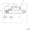
- Fig. 1 shows an industrial machine 10.
- the industrial machine 10 includes three computing devices 12, 14, 16.
- the computing devices 12, 14 can, for example, be designed as programmable logic controllers (PLC or PLC), whereas the computing device 16 is designed as a Windows device with an engineering system can be.
- PLC programmable logic controller
- the computing devices 12, 14, 16 are connected to one another by means of a data network 18 in the form of a fieldbus.
- the industrial machine 10 also includes a camera 20, a gripper 22 and a motor 24 of a conveyor belt 26.
- the field devices 20, 22, 24 are also connected to the data network 18.
- the conveyor belt 26 can be used to transport workpieces 28 to be processed by the industrial machine 10.
- the workpieces 28 are recorded by the camera 20. Based on the images recorded by the camera 20, defective workpieces 28 are to be recognized and sorted out using the gripper 22.
- An engineering system is executed on the computing device 16, which allows the programming and configuration of the field devices 20, 22, 24.
- the engineering system also determines which of the computing devices 12, 14, 16 carries out which parts of the programming and configuration.
- FIG. 2 A view is shown schematically, as it is also displayed to an operator of the engineering system.
- the view shows different function blocks FB1-FB5.
- the function blocks FB1-FB5 are connected to one another by graphic connectors 30.
- the graphical connectors 30 indicate how outputs of one function block are linked to inputs of another function block.
- the function blocks can fulfill different tasks.
- the function block FB1 can control the motor 24 and thus control the movement of the workpieces 28.
- an operator can specify that outputs of a function block forward information to other function blocks.
- the function block FB1 can inform the function block FB3 that a workpiece 28 is now present in the area of the camera 20.
- the function block FB3 can then instruct the camera 20 to take an image of the workpiece 28.
- the image from the camera 20 can then be transmitted to the function block FB4.
- AI artificial intelligence
- Fig. 3 now shows the steps an operator can take to configure the function block FB4 into an AI function block and begin execution of the AI function block.
- the operator selects an AI function block.
- a binary file with the AI model can then be selected in the second step.
- a file for the classification of the workpieces 28 is selected ("Workpiece_classification_model.onnx").
- an automatic adjustment 32 takes place, in which the inputs and outputs of the AI model are determined and the inputs and outputs of the AI function block are adjusted accordingly.
- the operator can execute the AI function block by clicking on “Deploy”.
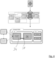
- a pod is generated from two containers, namely a runtime container 34 and an AI container 36.
- the containers 34, 36 communicate using shared memory areas 38.
- Additional containers can also be executed in another pod on the computing device 12.
- the runtime container 34 communicates with other runtime environments via the data network 18. Both the runtime container 34 and the other runtime environments that execute the other function blocks FB1, FB2, FB3 and FB5 work in accordance with IEC 61499.
- the other function blocks FB1, FB2, FB3 and FB5 can, for example, transmit image data from the camera 20 to the AI function block FB4.
- the runtime container 34 receives the data and transmits it to the AI container 36 via the shared memory area.
- the AI model carries out a classification in the AI container 36. Once the classification has been completed, the classification result is passed on to the other function blocks FB1, FB2, FB3 and FB5 via the runtime container 34.
- the Further function blocks can then use the classification result to determine, for example, whether the gripper 22 should sort out a workpiece 28.
Landscapes
- Engineering & Computer Science (AREA)
- Software Systems (AREA)
- Physics & Mathematics (AREA)
- Artificial Intelligence (AREA)
- General Physics & Mathematics (AREA)
- Theoretical Computer Science (AREA)
- Evolutionary Computation (AREA)
- Computing Systems (AREA)
- Computer Vision & Pattern Recognition (AREA)
- Medical Informatics (AREA)
- Automation & Control Theory (AREA)
- Health & Medical Sciences (AREA)
- Data Mining & Analysis (AREA)
- General Engineering & Computer Science (AREA)
- Mathematical Physics (AREA)
- Life Sciences & Earth Sciences (AREA)
- Biomedical Technology (AREA)
- Biophysics (AREA)
- Computational Linguistics (AREA)
- General Health & Medical Sciences (AREA)
- Molecular Biology (AREA)
- Programmable Controllers (AREA)
Abstract
Description
- Die vorliegende Erfindung betrifft ein Verfahren zum Integrieren zumindest eines KI-Funktionsblocks, welcher eine künstliche Intelligenz umfasst, in eine Steuerung für eine industrielle Maschine.
- Es ist grundsätzlich bekannt, sogenannte künstliche Intelligenzen, also Maschinenlernverfahren, neuronale Netze, Support-Vektormaschinen (SVMs) und dergleichen, in industriellen Verfahren einzusetzen. Ein solcher Einsatz erfolgt allerdings nicht standardmäßig.
- Daher ergeben sich für den Einsatz künstlicher Intelligenzen in industriellen Steuerungen häufig hohe Hürden. So bestehen viele verschiedene Architekturen für solche künstlichen Intelligenzen, die in unterschiedlichen Programmiersprachen und mit unterschiedlichen Schnittstellen implementiert sein können. Aufgrund der vielen Varianten können leicht Inkompatibilitäten bei der Integration und/oder Ausführung einer künstlichen Intelligenz in einer industriellen Steuerung entstehen. Die Integration einer künstlichen Intelligenz erfordert deshalb üblicherweise einen hohen Aufwand.
- Es ist daher die der Erfindung zugrunde liegende Aufgabe, ein Verfahren anzugeben, welches die Integration einer künstlichen Intelligenz in die Steuerung einer industriellen Maschine vereinfacht und beschleunigt.
- Diese Aufgabe wird durch ein Verfahren gemäß Anspruch 1 gelöst.
- Bei dem erfindungsgemäßen Verfahren wird für den KI-Funktionsblock ein KI-Modell zur Ausführung in dem KI-Funktionsblock ausgewählt, z.B. aus einer Vielzahl von KI-Modellen. Weiterhin wird der KI-Funktionsblock zumindest teilweise automatisiert mit weiteren Funktionsblöcken einer Steuerungssoftware der industriellen Maschine verknüpft. Schließlich wird der KI-Funktionsblock zumindest teilweise automatisiert zur Ausführung gebracht, wobei die Ausführung des KI-Funktionsblocks bevorzugt mittels einer IEC 61499 Laufzeitumgebung erfolgt.
- Die Erfindung stellt somit ein in großen Teilen automatisiertes Verfahren bereit, bei welchem ein Bediener z.B. lediglich angeben muss, dass überhaupt ein KI-Funktionsblock benötigt wird, welches KI-Modell in dem KI-Funktionsblock ausgeführt werden soll und wie der KI-Funktionsblock mit den weiteren Funktionsblöcken verbunden sein soll. Der Bediener benötigt somit nur wenige Klicks bis der KI-Funktionsblock funktionsfähig in die Steuerungssoftware der industriellen Maschine integriert ist und ausgeführt werden kann. Insbesondere benötigt der Bediener keine Kenntnisse über die zur Ausführung des KI-Modells benötigten Software-Bibliotheken (KI-Inferenzmaschinen). Ferner muss er sich auch nicht mit der Konfiguration der Kommunikation zwischen KI-Modell und Steuerungssoftware auseinandersetzen.
- Steuerungsaufgaben, die durch eine künstliche Intelligenz verbessert oder erleichtert werden können, können somit mit geringem Aufwand in die Steuerungssoftware integriert werden. Die Zeitdauer bis zur Funktionsfähigkeit ist dabei deutlich reduziert, wodurch beispielsweise Veränderungen an bestehenden Maschinen deutlich schneller erfolgen können, wodurch wiederum Produktionsausfälle verringert werden. Auch beim Aufbau neuer industrieller Maschinen wird eine Zeitverkürzung erreicht, wodurch die "Time-to-Market" reduziert werden kann.
- Bei der Steuerung der industriellen Maschine kann es sich beispielsweise um mehrere mittels eines Datennetzwerks verbundene Recheneinrichtungen (PLCs, Computer, etc.) handeln, die gemeinsam die Steuerung der industriellen Maschine bewirken. Die verschiedenen Recheneinrichtungen können dabei die durch die Funktionsblöcke vorgegebenen Funktionen ausführen.
- Die industrielle Maschine kann eine Vielzahl von Feldgeräten, beispielsweise Sensoren und Aktoren, umfassen. Die Feldgeräte sowie die Recheneinrichtungen können über das Datennetzwerk miteinander verbunden sein, wobei es sich bei dem Datennetzwerk bevorzugt um einen Feldbus (z.B. Sercos III, EtherCAT, EIP und dergleichen) handeln kann. Insbesondere basiert das Zusammenwirken der Recheneinrichtungen auf IEC 61499, wie später noch genauer ausgeführt. Bevorzugt werden die Funktionsblöcke auf verteilten Recheneinrichtungen ausgeführt. Zudem können die Funktionsblöcke ereignisbasiert ("eventbasiert") miteinander kommunizieren.
- Die Steuerungssoftware kann in Funktionsblöcke gegliedert sein, wobei bei der Konfiguration der Steuerungssoftware die Verbindungen bzw. Verknüpfungen zwischen den Funktionsblöcken definiert werden, sodass sich ein gewünschtes Steuerungsverhalten der Steuerungssoftware ergibt. Zumindest einer der Funktionsblöcke kann als KI-Funktionsblock ausgebildet sein, der zur Ausführung des KI-Modells ausgebildet ist. Das KI-Modell kann beispielsweise ein neuronales Netz, einen Machine-Learning-Algorithmus, eine Support-Vektormaschine (SVM) und dergleichen umfassen. Überdies kann das KI-Modell auch KI-Varianten außerhalb des Machine-Learning-Bereichs umfassen, beispielsweise regelbasierte KI-Systeme, KI-Systeme auf Basis logischer Schlussfolgerungen (Logic Reasoning), Planungs- und Optimierungsalgorithmen, Suchalgorithmen, etc. Die Vielzahl der einsetzbaren KI-Modelle ist ein Vorteil des hierin geschilderten Vorgehens, da die notwendige Laufzeitumgebung passend initialisiert und mit der Steuerungssoftware in Verbindung gebracht wird.
- Das KI-Modell kann beispielsweise eine Klassifizierungsaufgabe erfüllen oder eine Bildverarbeitung durchführen. Beispielsweise kann das KI-Modell ausgebildet sein, in dem industriellen Prozess hergestellte Teile auf ihre korrekte Form und/oder Anordnung hin zu überprüfen und ein entsprechendes Ergebnis auszugeben. Der KI-Funktionsblock kann daher beispielsweise mit weiteren Funktionsblöcken verknüpft sein, die dem KI-Funktionsblock die auszuwertenden Bilder übergeben und das Berechnungsergebnis des KI-Funktionsblocks weiterverarbeiten.
- Bei dem KI-Modell kann es sich insbesondere um ein bereits trainiertes Modell handeln, dass bereit für den Produktiveinsatz ist.
- Das Verknüpfen der Funktionsblöcke kann beispielsweise das grafische Verbinden der Funktionsblöcken in einer grafischen Benutzeroberfläche umfassen, beispielsweise durch grafische Elemente, welche insbesondere eine Verbindung eines Ausgangs eines Funktionsblocks mit einem Eingang eines anderen Funktionsblöcken anzeigen. Wird von einem Bediener eine solche Verbindung grafisch erzeugt, können automatisch die Kommunikationsschnittstellen geschaffen werden, um dann eine tatsächliche Datenverbindung zwischen den jeweiligen Funktionsblöcken zu schaffen.
- Ebenfalls kann das Verknüpfen eine Verknüpfung auf Code-Ebene umfassen, insbesondere durch Setzen von Ein- und Ausgangsvariablen, beispielsweise in einem Quellcode. Der KI-Funktionsblock ist damit in die Steuerung der industriellen Maschine eingebunden. Allgemein gesprochen, kann der KI-Funktionsblock also Sensordaten (Messwerte, Bilddaten und dergleichen) erhalten und auswerten. Überdies können die von dem KI-Funktionsblock erzeugten Berechnungsergebnisse für die Steuerung der Aktoren des industriellen Prozesses herangezogen werden.
- Durch die Verknüpfung der Funktionsblöcke wird insbesondere definiert, über welche Datenschnittstellen die Funktionsblöcke Daten, Ereignisse und dergleichen austauschen. Zudem kann definiert werden, welche Funktionsblöcke mit welchen anderen Funktionsblöcken kommunizieren. Die Funktionsblöcke können gemeinsam zumindest einen Teil der Steuerungssoftware der industriellen Maschine bilden.
- Wie später noch genauer ausgeführt wird, kann z.B. automatisch erkannt werden, welche Ein- und Ausgänge das KI-Modell und damit der KI-Funktionsblock benötigt, wodurch dann die Verknüpfung zu den weiteren Funktionsblöcken entsprechend (automatisch) angepasst werden kann.
- Das zumindest teilweise automatisierte zur Ausführung bringen des KI-Funktionsblocks kann ein Deployment umfassen. Wie ebenfalls später noch detailliert ausgeführt wird, kann dazu die ausführende Recheneinrichtung (d.h. der Compute-Host) insbesondere automatisch ermittelt werden, wobei der KI-Funktionsblock dann auf der ausführenden Recheneinrichtung zur Ausführung gebracht wird. Die Ausführung des KI-Funktionsblocks erfolgt dabei erfindungsgemäß mittels einer IEC 61499 Laufzeitumgebung oder in einer IEC 61499 Laufzeitumgebung (Runtime Environment - RTE).
- Die Laufzeitumgebung nach IEC 61499 umfasst insbesondere die Fähigkeit, dass eine Applikation (d.h. der KI-Funktionsblock und/oder die weiteren Funktionsblöcke bzw. ein Netzwerk von Funktionsblöcken) auf mehrere Recheneinrichtungen (Compute-Hosts) verteilt werden kann. Auf jedem Compute-Host läuft eine eigene IEC 61499 Laufzeitumgebung. Die notwendige Kommunikation ("Cross-Communication") zwischen den Laufzeitumgebungen wird bevorzugt von den Laufzeitumgebungen nach IEC 61499 automatisch generiert.
- Beispielsweise bedeutet dies, dass eine IEC 61499 Laufzeitumgebung auf dem am besten passenden Compute-Host initialisiert wird. In dieser Laufzeitumgebung wird dann z.B. nur ein einziger Funktionsblock ausgeführt, insbesondere der KI-Funktionsblock. Neben der IEC 61499 Laufzeitumgebung wird auf diesem Compute-Host, insbesondere automatisch, auch eine Laufzeitumgebung für das KI-Modell aufgesetzt. Beim automatischen Aufsetzen der Laufzeitumgebung für das KI-Modell wird sichergestellt, dass die Laufzeitumgebung zum KI-Modell passt, z.B. kann TensorFlow oder ONNX für Neuronale Netze oder eine mlpack Library für Machine Learning Modelle verwendet werden. Die beiden Laufzeitumgebungen auf demselben Compute-Host können dann sehr effizient Daten miteinander austauschen, um u.a. Echtzeitanforderungen zu erfüllen.
- Bei IEC 61499 handelt es sich um eine ereignisbasierte Programmiersprache (Event Driven Language). Eine IEC 61499 Laufzeitumgebung erlaubt die Ausführung der Steuerungssoftware auf verschiedenen verteilten Hardwareressourcen, beispielsweise PLCs und/oder Linux und/oder Windows Geräten. Für jeden Funktionsblock in der IEC 61499 Laufzeitumgebung kann die ausführende Hardware und/oder die ausführende Recheneinrichtung einzeln bestimmt werden. Auf diese Weise können manche Funktionsblöcken beispielsweise auf einem Linux System, andere Funktionsblöcken hingegen auf einem Windows System ausgeführt werden.
- Durch die erfindungsgemäße Nutzung der IEC 61499 Laufzeitumgebung kann der KI-Funktionsblock flexibel in eine verteilte Architektur von Recheneinrichtungen integriert werden, wobei der KI-Funktionsblock dadurch auf einfache Weise auf einer geeigneten Recheneinrichtung (z.B. mit ausreichend Rechenleistung) ausgeführt werden kann. Durch die IEC 61499 Laufzeitumgebung wird zudem sichergestellt, dass die Kommunikation zwischen dem KI-Funktionsblock und den weiteren Funktionsblöcken der Steuerungssoftware (gegebenenfalls auf anderen Recheneinrichtungen) automatisch korrekt erfolgt. Die Kommunikation kann dabei über das vorgenannte Datennetzwerk erfolgen.
- Weitere Ausführungsformen der Erfindung sind der Beschreibung, den Unteransprüchen sowie den Zeichnungen zu entnehmen.
- Gemäß einer ersten Ausführungsform sind der KI-Funktionsblock und/oder die weiteren Funktionsblöcke Funktionsblöcke gemäß IEC 61499. Dies bedeutet insbesondere, dass die Funktionsblöcken durch Ereignisse (Events) aktiviert werden können und selbst auch Ereignisse erzeugen können, um andere Funktionsblöcken zu aktivieren. Die Funktionsblöcke und insbesondere der KI-Funktionsblock erscheinen zumindest von extern als IEC 61499 Funktionsblöcke. Der interne Aufbau des KI-Funktionsblocks wird nachfolgend noch detailliert beschrieben.
- Gemäß einer weiteren Ausführungsform umfasst der KI-Funktionsblock einen Runtime-Container, welcher die IEC 61499 Laufzeitumgebung zur Verfügung stellt, und einen KI-Container, in welchem die künstliche Intelligenz ausgeführt wird, wobei der Runtime-Container und der KI-Container miteinander kommunizieren. Allgemein gesprochen kann der KI-Funktionsblock somit in einer virtualisierten Umgebung ausgeführt werden.
- Der Runtime-Container stellt bevorzugt Datenschnittstellen zu den weiteren Funktionsblöcken bereit. Durch die Kommunikation des Runtime-Containers mit dem KI-Container wird es bevorzugt ermöglicht, die KI-Funktionen auszuführen. In dem KI-Container wird das KI-Modell ausgeführt. Hierbei ergibt sich insbesondere der Vorteil, dass durch die Kommunikation des KI-Containers mit der IEC 61499 Laufzeitumgebung, die Kommunikation mit den weiteren Funktionsblöcken automatisch in einem Datenformat erfolgen kann, welches auch für die weiteren Funktionsblöcken (die beispielsweise gemäß IEC 61499 ausgebildet sind) passend ist. Durch die Bereitstellung der IEC 61499 Funktionalität durch den Runtime-Container wird die Funktionalität des KI-Modells direkt auf dem Control Code Level integriert, d.h. direkt in die Steuerungssoftware integriert.
- Bevorzugt führt der Runtime-Container eine virtuelle IEC 61499 Laufzeitumgebung aus. Je nach ausgewählten KI-Modell kann der jeweils benötigte KI-Container ermittelt werden, bevorzugt automatisch. Der KI-Container stellt dabei das "Inference-Environment" für das KI-Modell bereit. Insbesondere können verschiedene KI-Container benötigt werden, je nachdem ob das KI-Modell beispielsweise in PyTorch, ONNX, KERAS, Tensorflow und dergleichen erstellt wurde. Bei dem KI-Container und/oder dem Runtime-Container kann es sich beispielsweise um einen Docker-Container einen LXC-Container, einen containerd-Container und dergleichen handeln.
- Der benötigte KI-Container kann zunächst basierend auf dem KI-Modell vorausgewählt werden. So kann für ein KI-Modell, welches ein Neuronales Netz ist, ein KI-Container mit einem passenden Framework (z.B. Tensorflow, PyTorch oder ONNX) vorausgewählt werden. Hingegen für ein KI-Modell mit einem Machine Learning Modell (z.B. SVM) kann stattdessen ein KI-Container mit einem Framework basierend auf "mlpack" vorausgewählt werden. In einem zweiten Schritt kann dann ein KI-Container mit der passenden Version des Frameworks (z.B. Tensorflow 1 oder Tensorflow 2) ausgewählt und verwendet werden.
- Insbesondere steht eine Sammlung von KI-Containern zur Verfügung, welche bevorzugt die entsprechende Laufzeitumgebung kapseln, wobei auf Basis des KI-Modells der am besten passende KI-Container ausgewählt wird. Hierdurch ist es möglich, eine breite Vielfalt an KI-Modellen automatisch zur Ausführung zu bringen. Eine Beschränkung z.B. nur auf Neuronale Netze in Tensorflow 1 kann entfallen.
- Gemäß einer weiteren Ausführungsform wird die Steuerungssoftware auf mehreren verschiedenen, mittels eines Datennetzwerks verbundenen Recheneinrichtungen ausgeführt, wobei eine der Recheneinrichtungen automatisiert für die Ausführung des KI-Funktionsblocks ausgewählt wird, beispielsweise anhand der verfügbaren Rechenleistung der Recheneinrichtung. Gemäß dem Verfahren kann also überprüft werden, welche der Recheneinrichtungen am geeignetsten für die Ausführung des KI-Funktionsblocks ist. Neben der verfügbaren Rechenleistung der Recheneinrichtung kann alternativ oder zusätzlich auch beispielsweise das Vorhandensein spezieller für die Ausführung von Maschinenlernverfahren eingerichteter Hardware in der Recheneinrichtung ausschlaggebend sein. Nach der Auswahl der Recheneinrichtung (d.h. des Compute-Hosts) erfolgt eine Initialisierung auf der ausgewählten Recheneinrichtung. Dabei kann ein sogenannter POD gebildet werden, welcher mehrere Container umfasst. Insbesondere kann der KI-Container und der Runtime-Container gemeinsam auf der Recheneinrichtung initialisiert werden.
- Gemäß einer weiteren Ausführungsform werden der Runtime-Container und der KI-Container automatisch auf der ausgewählten Recheneinrichtung initialisiert. Bevorzugt handelt es sich für den Runtime-Container und den KI-Container um dieselbe Recheneinrichtung.
- Gemäß einer weiteren Ausführungsform erfolgt nach dem Initialisieren des KI-Containers ein, bevorzugt automatisches, Deployment des ausgewählten KI-Modells in den KI-Container. Alternativ oder zusätzlich erfolgt nach dem Initialisieren des Runtime-Containers ein, insbesondere automatisches, Deployment, bevorzugt einer Instanz, des Runtime-Containers auf die ausgewählte Recheneinrichtung. Als Deployment (Softwareverteilung) wird insbesondere die halb- oder vollautomatisierte Installation und Konfiguration von Software (hier des KI-Containers und/oder des Runtime-Containers) bezeichnet.
- Gemäß einer weiteren Ausführungsform werden der KI-Container und der Runtime-Container auf derselben Hardware ausgeführt und kommunizieren insbesondere direkt über die gemeinsame Hardware, beispielsweise über gemeinsam genutzte Speicherbereiche. Die Kommunikation auf derselben Hardware kann somit sehr schnell und Latenzarm erfolgen, wodurch die Funktion der künstlichen Intelligenz beschleunigt werden kann.
- Gemäß einer weiteren Ausführungsform werden die Kommunikationsschnittstellen zwischen dem KI-Container und dem Runtime-Container automatisch konfiguriert. Insbesondere werden für die Konfiguration der Kommunikationsschnittstellen zwischen dem KI-Container und dem Runtime-Container die Eingänge und die Ausgänge des KI-Modells, bevorzugt automatisch, ermittelt und die Kommunikationsschnittstellen zwischen dem KI-Container und dem Runtime-Container an die Eingänge und die Ausgänge angepasst. Wird beispielsweise festgestellt, dass das KI-Modell mehrere verschiedene Eingänge mit verschiedenen Datentypen benötigt, das KI-Modell aber nur einen Ausgang eines einzigen Datentyps bereitstellt, so kann der Runtime-Container Kommunikationsschnittstellen (d.h. Datenschnittstellen) bereitstellen, über die dem KI-Modell genau die benötigten Eingänge bereitgestellt werden und über die das vom KI-Modell ermittelte Ergebnis an dem Ausgang abgerufen werden kann.
- Überdies kann der Runtime-Container nach extern, d.h. für die weiteren Funktionsblöcke, die von dem KI-Modell benötigten Eingänge und Ausgänge bereitstellen. Im vorliegenden Beispiel würde der KI-Funktionsblock dann mehrere Eingänge mit den unterschiedlichen Datentypen und den einen genannten Ausgang umfassen. Die Ein- und Ausgänge des KI-Funktionsblocks stehen dann den weiteren Funktionsblöcken zur Verknüpfung zur Verfügung. Insbesondere können die automatisch ermittelten Eingänge und Ausgänge einem Bediener grafisch in einer grafischen Benutzeroberfläche angezeigt werden. Beispielsweise können die Ein- und Ausgänge des KI-Funktionsblocks basierend auf Informationen, insbesondere basierend auf Meta-Daten, des KI-Modells ermittelt werden. Die Meta-Daten können für neuronale Netze z.B. die "Input Shapes" und "Output Shapes" umfassen, d.h. die Dimensionen der Tensoren/Matrizen der Ein- und Ausgänge.
- Gemäß einer weiteren Ausführungsform wird das Verfahren durch einen Bediener angestoßen, wobei der Bediener zunächst einen KI-Funktionsblock und anschließend das KI-Modell insbesondere in Form einer ausführbaren Datei oder einer Binärdatei, für den KI-Funktionsblock auswählt. Danach kann der Bediener zusätzlich das Deployment anstoßen. Insgesamt kann es somit lediglich notwendig sein, drei Schritte auszuführen (Auswahl des KI-Funktionsblocks, Auswahl des KI-Modells und Anstoßen des Deployments). Durch diese drei Schritte kann der Bediener grafisch in einer grafischen Bedienoberfläche geführt werden. Dabei kann der Bediener dann im ersten Schritt grafisch den KI-Funktionsblock auswählen. Im zweiten Schritt kann der Bediener das KI-Modell auswählen, beispielsweise durch Auswahl aus einer Dropdownliste oder durch Angabe einer Datei mit dem KI-Modell. Durch die Auswahl einer ausführbaren Datei und/oder einer Binärdatei kann das KI-Modell direkt in dem KI-Funktionsblock ausgeführt werden, ohne dass beispielsweise ein Kompilieren notwendig ist. Im letzten Schritt kann der Bediener dann das Deployment anstoßen, woraufhin dann automatisch die Recheneinrichtung ausgewählt und der Funktionsblock auf der Recheneinrichtung ausgeführt wird. Die vorgenannten Schritte können dem Bediener insbesondere von einem Engineering System angezeigt werden. Bei dem Engineering System kann es sich um eine Software und/oder Hardware zur Konfiguration und Programmierung der Recheneinrichtungen der industriellen Maschine handeln. Das Engineering System kann die Konfiguration der Recheneinrichtungen gemäß IEC 61499 vornehmen.
- Weiterer Gegenstand der Erfindung ist eine industrielle Maschine, welche ausgebildet ist,
- ein Auswählen eines KI-Modells für einen KI-Funktionsblock zu ermöglichen, wobei das KI-Modell in dem KI-Funktionsblock ausgeführt wird,
- den KI-Funktionsblock zumindest teilweise automatisiert mit weiteren Funktionsblöcken einer Steuerungssoftware der industriellen Maschine zu verknüpfen,
- den KI-Funktionsblock zumindest teilweise automatisiert zur Ausführung zu bringen, wobei die Ausführung des KI-Funktionsblocks mittels einer IEC 61499 Laufzeitumgebung erfolgt.
- Die vorgenannten Funktionen der industriellen Maschine können beispielsweise durch ein Engineering System bereitgestellt werden, welches Teil der industriellen Maschine sein kann. Insbesondere kann das Engineering System eine Recheneinrichtung umfassen, die zumindest zeitweise über ein Datennetzwerks mit der industriellen Maschine verbunden wird.
- Gemäß einer Ausführungsform der industriellen Maschine umfasst die industrielle Maschine mehrere Recheneinrichtungen, wobei verschiedene Recheneinrichtungen verschiedene der weiteren Funktionsblöcken ausführen und die Funktionsblöcken gemäß IEC 61499 miteinander kommunizieren. Die Funktionen der industriellen Maschine werden also bevorzugt mittels verteilter Hardware gesteuert.
- Schließlich betrifft die Erfindung noch ein Computerprogrammprodukt, umfassend Befehle, die bei der Ausführung des Programms durch einen Computer (oder durch eine oder mehrere der vorgenannten Recheneinrichtungen) diese(n) veranlassen, dass hierin beschriebene Verfahren auszuführen.
- Die Ausführungen zu dem erfindungsgemäßen Verfahren gelten für die erfindungsgemäße industrielle Maschine und das erfindungsgemäß Computerprogrammprodukt entsprechend. Dies gilt insbesondere hinsichtlich Vorteilen und bevorzugten Ausführungsformen. Es versteht sich, dass sämtliche hierin genannten Ausführungsformen und Merkmale miteinander kombiniert werden können, sofern nicht explizit etwas Gegenteiliges angegeben ist.
- Nachfolgend wird die Erfindung rein beispielhaft unter Bezugnahme auf die Zeichnungen beschrieben. Es zeigen:
-
Fig. 1 eine schematische Ansicht einer industriellen Maschine mit mehreren Recheneinrichtungen; -
Fig. 2 miteinander verknüpfte Funktionsblöcke zur Steuerung der industriellen Maschine; -
Fig. 3 Schritte zur Integration einer künstlichen Intelligenz in einen Funktionsblock; -
Fig. 4 schematisch die Ausführung eines KI-Funktionsblocks auf einer Recheneinrichtung. -
Fig. 1 zeigt eine industrielle Maschine 10. Die industrielle Maschine 10 umfasst drei Recheneinrichtungen 12, 14, 16. Die Recheneinrichtungen 12,14 können beispielsweise als speicherprogrammierbare Steuerungen (SPS oder PLC) ausgeführt sein, wohingegen die Recheneinrichtung 16 als Windows-Gerät mit einem Engineering System ausgeführt sein kann. - Die Recheneinrichtungen 12, 14, 16 sind mittels eines Datennetzwerks 18 in Form eines Feldbusses miteinander verbunden. Die industrielle Maschine 10 umfasst zudem eine Kamera 20, einen Greifer 22 sowie einen Motor 24 eines Förderband 26. Die Feldgeräte 20, 22, 24 sind ebenfalls an das Datennetzwerk 18 angeschlossen. Mit dem Förderband 26 können von der industriellen Maschine 10 zu verarbeitenden Werkstücke 28 transportiert werden.
- Die Werkstücke 28 werden dabei von der Kamera 20 aufgenommen. Anhand der von der Kamera 20 aufgenommenen Bilder sollen fehlerhafte Werkstücke 28 erkannt und mittels des Greifers 22 aussortiert werden.
- Auf der Recheneinrichtung 16 wird ein Engineering System ausgeführt, welches die Programmierung und Konfiguration der Feldgeräte 20, 22, 24 erlaubt. Das Engineering System legt auch fest, welche der Recheneinrichtungen 12, 14, 16 welche Teile der Programmierung und Konfiguration ausführt.
- In
Fig. 2 ist schematisch eine Ansicht gezeigt, wie sie auch einem Bediener des Engineering Systems angezeigt wird. Die Ansicht zeigt verschiedene Funktionsblöcke FB1-FB5. Die Funktionsblöcke FB1-FB5 sind durch grafische Verbinder 30 miteinander verbunden. Die grafischen Verbinder 30 geben an, wie Ausgänge eines Funktionsblocks mit Eingängen eines anderen Funktionsblocks verknüpft sind. - Die Funktionsblöcke können unterschiedliche Aufgaben erfüllen. Beispielsweise kann der Funktionsblock FB1 die Steuerung des Motors 24 bewirken und so die Bewegung der Werkstücke 28 Steuern. Über die grafischen Verbinder 30 kann ein Bediener festlegen, dass Ausgänge eines Funktionsblocks anderen Funktionsblöcken Informationen weiterleiten. Beispielsweise kann nach dem Bewegen eines Werkstücks 28 der Funktionsblock FB1 dem Funktionsblock FB3 mitteilen, dass nun ein Werkstück 28 im Bereich der Kamera 20 vorliegt. Der Funktionsblock FB3 kann dann die Kamera 20 anweisen, ein Bild des Werkstücks 28 aufzunehmen. Das Bild der Kamera 20 kann anschließend an den Funktionsblock FB4 übertragen werden.
- Im Funktionsblock FB4 soll nun eine künstliche Intelligenz ("AI" in
Fig. 2 undFig. 4 ) dazu ausgeführt werden, die im Funktionsblock FB3 erzeugten Bilder auszuwerten. -
Fig. 3 zeigt nun die Schritte, die ein Bediener durchführen kann, um den Funktionsblock FB4 zu einem KI-Funktionsblock zu konfigurieren und die Ausführung des KI-Funktionsblocks zu beginnen. Im ersten Schritt wählt der Bediener einen KI-Funktionsblock aus. Durch einen Klick auf Konfigurieren ("Configure") kann dann im zweiten Schritt eine Binärdatei mit dem KI-Modell ausgewählt werden. Im vorliegenden Beispiel wird eine Datei für die Klassifikation der Werkstücke 28 ausgewählt ("Workpiece_classification_model.onnx"). Nach dem Auswählen erfolgt eine automatische Anpassung 32, bei welcher die Ein- und Ausgänge des KI-Modells ermittelt werden und die Ein- und Ausgänge des KI-Funktionsblocks entsprechend angepasst werden. Schließlich kann der Bediener im dritten Schritt durch einen Klick auf "Deploy" den KI-Funktionsblock zur Ausführung bringen. - Dadurch wird, wie in
Fig. 4 gezeigt beispielsweise auf der Recheneinrichtung 12 ein Pod aus zwei Containern, nämlich einem Runtime-Container 34 und einem KI-Container 36 erzeugt. Die Container 34, 36 kommunizieren mittels geteilter Speicherbereiche 38. - Auf der Recheneinrichtung 12 können in einem anderen Pod auch noch weitere Container ausgeführt werden. Der Runtime-Container 34 kommuniziert über das Datennetzwerk 18 mit weiteren Laufzeitumgebungen. Sowohl der Runtime-Container 34 als auch die weiteren Laufzeitumgebungen, welche die weiteren Funktionsblöcke FB1, FB2, FB3 und FB5 ausführen, arbeiten gemäß IEC 61499.
- Im Betrieb können die weiteren Funktionsblöcke FB1, FB2, FB3 und FB5 beispielsweise Bilddaten der Kamera 20 an den KI-Funktionsblock FB4 übermitteln. Dort nimmt der Runtime-Container 34 die Daten in Empfang und übermittelt sie über den gemeinsam genutzten Speicherbereich an den KI-Container 36. In dem KI-Container 36 führt das KI-Modell eine Klassifikation durch. Ist die Klassifikation abgeschlossen, so wird das Klassifikationsergebnis über den Runtime-Container 34 an die weiteren Funktionsblöcken FB1, FB2, FB3 und FB5 übergeben. Die weiteren Funktionsblöcken können dann anhand des Klassifikationsergebnisses beispielsweise feststellen, ob der Greifer 22 ein Werkstück 28 aussortieren soll.
- Insgesamt ist es für einen Bediener somit mit wenigen Klicks möglich, ein komplexes KI-Modell in die Steuerung der industriellen Maschine 10 zu integrieren.
-
- 10
- industrielle Maschine
- 12
- Recheneinrichtung
- 14
- Recheneinrichtung
- 16
- Recheneinrichtung
- 18
- Datennetzwerks
- 20
- Kamera
- 22
- Greifer
- 24
- Motor
- 26
- Förderband
- 28
- Werkstücke
- 30
- grafische Verbinder
- 32
- automatische Anpassung
- 34
- Runtime-Container
- 36
- KI-Container
- 38
- gemeinsam genutzter Speicherbereich
- FB1
- Funktionsblock
- FB2
- Funktionsblock
- FB3
- Funktionsblock
- FB4
- KI-Funktionsblock
- FB5
- Funktionsblock
Claims (13)
- Verfahren zum Integrieren zumindest eines KI-Funktionsblocks (FB4), welcher eine künstliche Intelligenz umfasst, in eine Steuerung für eine industrielle Maschine (10), wobei bei dem Verfahren- für den KI-Funktionsblock (FB4) ein KI-Modell zur Ausführung in dem KI-Funktionsblock (FB4) ausgewählt wird,- der KI-Funktionsblock (FB4) zumindest teilweise automatisiert mit weiteren Funktionsblöcken (FB1-FB3, FB5) einer Steuerungssoftware der industriellen Maschine (10) verknüpft wird,- der KI-Funktionsblock (FB4) zumindest teilweise automatisiert zur Ausführung gebracht wird, wobei die Ausführung des KI-Funktionsblocks (FB4) mittels einer IEC 61499 Laufzeitumgebung erfolgt.
- Verfahren nach Anspruch 1,
wobei der KI-Funktionsblock (FB4) und die weiteren Funktionsblöcke (FB1-FB3, FB5) Funktionsblöcke gemäß IEC 61499 sind. - Verfahren nach Anspruch 1 oder 2,
wobei der KI-Funktionsblock (FB4) einen Runtime-Container (34), welcher die IEC 61499 Laufzeitumgebung zur Verfügung stellt, und einen KI-Container (36), in welchem die künstliche Intelligenz ausgeführt wird, umfasst, wobei der Runtime-Container (34) und der KI-Container (36) miteinander kommunizieren. - Verfahren nach einem der vorstehenden Ansprüche,
wobei die Steuerungssoftware auf mehreren verschiedenen, mittels eines Datennetzwerks verbundenen Recheneinrichtungen (12-16) ausgeführt wird, wobei eine der Recheneinrichtungen (12-16) automatisiert für die Ausführung des KI-Funktionsblocks (FB4) ausgewählt wird, beispielsweise anhand der verfügbaren Rechenleistung der Recheneinrichtung (12-16). - Verfahren nach Ansprüchen 3 und 4,
wobei der Runtime-Container (34) und der KI-Container (36) automatisch auf der ausgewählten Recheneinrichtung (12-16) initialisiert werden. - Verfahren nach Anspruch 5,
wobei nach dem Initialisieren des KI-Containers (36) ein Deployment des ausgewählten KI-Modells in den KI-Container (36) erfolgt und/oder nach dem Initialisieren des Runtime-Containers (34) ein, insbesondere automatisches, Deployment, bevorzugt einer Instanz, des Runtime-Containers (34) auf die ausgewählte Recheneinrichtung (12-16) erfolgt. - Verfahren nach zumindest einem der Ansprüche 3 bis 6,
wobei der KI-Container (36) und der Runtime-Container (34) auf derselben Hardware ausgeführt werden und direkt über die gemeinsame Hardware kommunizieren, beispielsweise über gemeinsam genutzte Speicherbereiche. - Verfahren nach zumindest einem der Ansprüche 3 bis 7,
wobei die Kommunikationsschnittstellen zwischen dem KI-Container (36) und dem Runtime-Container (34) automatisch konfiguriert werden. - Verfahren nach Anspruch 8,
wobei für die Konfiguration der Kommunikationsschnittstellen zwischen dem KI-Container (36) und dem Runtime-Container (34) die Eingänge und die Ausgänge des KI-Modells, bevorzugt automatisch, ermittelt werden und die Kommunikationsschnittstellen zwischen dem KI-Container (36) und dem Runtime-Container (34) an die Eingänge und Ausgänge angepasst werden. - Verfahren nach einem der vorstehenden Ansprüche,
wobei das Verfahren durch einen Bediener angestoßen wird, wobei der Bediener zunächst einen KI-Funktionsblock (FB4) und anschließend das KI-Modell, insbesondere in Form einer ausführbaren Datei oder einer Binärdatei, für den KI-Funktionsblock (FB4) auswählt. - Industrielle Maschine (10), welche ausgebildet ist,- ein Auswählen eines KI-Modells für einen KI-Funktionsblock (FB4) zu ermöglichen, wobei das KI-Modell in dem KI-Funktionsblock (FB4) ausgeführt wird,- den KI-Funktionsblock (FB4) zumindest teilweise automatisiert mit weiteren Funktionsblöcken (FB1-FB3, FB5) einer Steuerungssoftware der industriellen Maschine (10) zu verknüpfen,- den KI-Funktionsblock (FB4) zumindest teilweise automatisiert zur Ausführung zu bringen, wobei die Ausführung des KI-Funktionsblocks (FB4) mittels einer IEC 61499 Laufzeitumgebung erfolgt.
- Industrielle Maschine (10) nach Anspruch 11, wobei die industrielle Maschine (10) mehrere Recheneinrichtungen (12-16) umfasst, wobei verschiedene Recheneinrichtungen (12-16) verschiedene der weiteren Funktionsblöcke (FB1-FB3, FB5) ausführen und die Funktionsblöcke gemäß IEC 61499 miteinander kommunizieren.
- Computerprogrammprodukt, umfassend Befehle, die bei der Ausführung des Programms durch einen Computer diesen veranlassen, das Verfahren nach zumindest einem der Ansprüche 1 bis 10 auszuführen.
Priority Applications (3)
| Application Number | Priority Date | Filing Date | Title |
|---|---|---|---|
| EP22305875.1A EP4293443B1 (de) | 2022-06-15 | 2022-06-15 | Verfahren zum integrieren eines funktionsblocks mit künstlicher intelligenz |
| CN202310703382.3A CN117234535A (zh) | 2022-06-15 | 2023-06-14 | 用于将功能块与人工智能集成的方法 |
| US18/209,525 US20240142918A1 (en) | 2022-06-15 | 2023-06-14 | Method of integrating a function block with artificial intelligence |
Applications Claiming Priority (1)
| Application Number | Priority Date | Filing Date | Title |
|---|---|---|---|
| EP22305875.1A EP4293443B1 (de) | 2022-06-15 | 2022-06-15 | Verfahren zum integrieren eines funktionsblocks mit künstlicher intelligenz |
Publications (2)
| Publication Number | Publication Date |
|---|---|
| EP4293443A1 true EP4293443A1 (de) | 2023-12-20 |
| EP4293443B1 EP4293443B1 (de) | 2025-07-30 |
Family
ID=82399409
Family Applications (1)
| Application Number | Title | Priority Date | Filing Date |
|---|---|---|---|
| EP22305875.1A Active EP4293443B1 (de) | 2022-06-15 | 2022-06-15 | Verfahren zum integrieren eines funktionsblocks mit künstlicher intelligenz |
Country Status (3)
| Country | Link |
|---|---|
| US (1) | US20240142918A1 (de) |
| EP (1) | EP4293443B1 (de) |
| CN (1) | CN117234535A (de) |
Citations (4)
| Publication number | Priority date | Publication date | Assignee | Title |
|---|---|---|---|---|
| WO2020040721A1 (en) * | 2018-08-20 | 2020-02-27 | Siemens Aktiengesellschaft | Programmable logic controller-based modular acceleration module for artificial intelligence |
| DE102018216456A1 (de) * | 2018-09-26 | 2020-03-26 | Siemens Aktiengesellschaft | Integration von Funktionskomponenten einer technischen Anlage |
| EP3671571A1 (de) * | 2018-12-20 | 2020-06-24 | Siemens Aktiengesellschaft | Verfahren und system zur erzeugung eines modells für künstliche intelligenz |
| WO2021076093A1 (en) * | 2019-10-14 | 2021-04-22 | Siemens Aktiengesellschaft | Artificial intelligence (ai) companions for function blocks in a programmable logic controller (plc) program for integrating ai in automation |
Family Cites Families (4)
| Publication number | Priority date | Publication date | Assignee | Title |
|---|---|---|---|---|
| US11100423B2 (en) * | 2016-01-27 | 2021-08-24 | Microsoft Technology Licensing, Llc | Artificial intelligence engine hosted on an online platform |
| US20210397171A1 (en) * | 2020-06-22 | 2021-12-23 | Rockwell Automation Technologies, Inc. | Industrial automation hmi program file generation from computer-aided design |
| US11625683B2 (en) * | 2021-01-14 | 2023-04-11 | Rockwell Automation Technologies, Inc. | System and method of industrial automation multi-developer control code change commits |
| US20220397875A1 (en) * | 2021-06-11 | 2022-12-15 | Nxtcontrol Gmbh | Runtime Environment and Method for Creating an Event-Driven Execution Model of an Industrial Application |
-
2022
- 2022-06-15 EP EP22305875.1A patent/EP4293443B1/de active Active
-
2023
- 2023-06-14 CN CN202310703382.3A patent/CN117234535A/zh active Pending
- 2023-06-14 US US18/209,525 patent/US20240142918A1/en active Pending
Patent Citations (4)
| Publication number | Priority date | Publication date | Assignee | Title |
|---|---|---|---|---|
| WO2020040721A1 (en) * | 2018-08-20 | 2020-02-27 | Siemens Aktiengesellschaft | Programmable logic controller-based modular acceleration module for artificial intelligence |
| DE102018216456A1 (de) * | 2018-09-26 | 2020-03-26 | Siemens Aktiengesellschaft | Integration von Funktionskomponenten einer technischen Anlage |
| EP3671571A1 (de) * | 2018-12-20 | 2020-06-24 | Siemens Aktiengesellschaft | Verfahren und system zur erzeugung eines modells für künstliche intelligenz |
| WO2021076093A1 (en) * | 2019-10-14 | 2021-04-22 | Siemens Aktiengesellschaft | Artificial intelligence (ai) companions for function blocks in a programmable logic controller (plc) program for integrating ai in automation |
Non-Patent Citations (1)
| Title |
|---|
| LYU GUOLIN ET AL: "Towards IEC 61499-Based Distributed Intelligent Automation: A Literature Review", IEEE TRANSACTIONS ON INDUSTRIAL INFORMATICS, IEEE SERVICE CENTER, NEW YORK, NY, US, vol. 17, no. 4, 17 August 2020 (2020-08-17), pages 2295 - 2306, XP011831147, ISSN: 1551-3203, [retrieved on 20210111], DOI: 10.1109/TII.2020.3016990 * |
Also Published As
| Publication number | Publication date |
|---|---|
| EP4293443B1 (de) | 2025-07-30 |
| US20240142918A1 (en) | 2024-05-02 |
| CN117234535A (zh) | 2023-12-15 |
Similar Documents
| Publication | Publication Date | Title |
|---|---|---|
| EP3542232B1 (de) | Steuerung für eine industrielle automatisierungsanlage und verfahren zum programmieren und betreiben einer derartigen steuerung | |
| DE102017003943A1 (de) | Zellensteuervorrichtung zum Optimieren von Bewegungen eines Produktionssystems, das Industriemaschinen umfasst | |
| EP3931653B1 (de) | Verfahren zum engineering und simulation eines automatisierungssystems mittels digitaler zwillinge | |
| EP3067768B1 (de) | Automatisierungseinrichtung und Operator-System | |
| DE102017120016A1 (de) | Verfahren zur Konfiguration eines zum Testen eines elektronischen Steuergeräts eingerichteten Testgeräts sowie Konfigurationssystem | |
| EP3953865B1 (de) | Verfahren, vorrichtung und computerprogramm zum betreiben eines tiefen neuronalen netzes | |
| EP2732347B1 (de) | Verfahren und system zur dynamischen verteilung von programmfunktionen in verteilten steuerungssystemen | |
| DE102020102862B4 (de) | Computerimplementiertes Verfahren, Vorrichtung, Computerprogramm undVerwendung des Verfahrens zum Bereitstellen von auf Funktionalität verifizierten grafischen Programmanweisungen | |
| EP3058425B1 (de) | Vorrichtung und verfahren zur änderung von betriebseinstellungen einer technischen anlage | |
| BE1026448B1 (de) | Verfahren und Vorrichtung zur Konfiguration einer Hardwarekomponente | |
| EP4293443B1 (de) | Verfahren zum integrieren eines funktionsblocks mit künstlicher intelligenz | |
| DE102017007909A1 (de) | Produktionssteuerung, ausgestattet mit einer Funktion zur Identifizierung der Ursache nach einem Betriebsstop einer Produktionseinrichtung, die Fertigungseinrichtungen umfasst | |
| WO2014154281A1 (de) | Objektbasierte konfiguration einer prozess- und/oder fertigungsanlage | |
| WO2025219164A1 (de) | Verfahren zur erzeugung eines steuerprogramms einer speicherprogrammierbaren steuerung und automatisierungssystem | |
| EP3764185A1 (de) | Verfahren zum testen eines systems | |
| EP3392725B1 (de) | Vorschlagen und/oder erstellen von agenten in einem industriellen automatisierungssystem | |
| EP4147121B1 (de) | Verfahren zum erstellen und ausführen eines steuerprogramms zum steuern eines automatisierungssystems und automatisierungssystem | |
| DE102016121788A1 (de) | Konfiguration einer Automatisierungsanlage | |
| EP3757688B1 (de) | Verfahren zur konfiguration einer industriellen maschine | |
| EP3575898A1 (de) | Speicherprogrammierbare steuerung und betriebsverfahren für virtuelle speicherprogrammierbare steuerung und computerprogrammprodukt | |
| EP3948449B1 (de) | Verfahren und engineering-system zur änderung eines programms einer industriellen automatisierungskomponente | |
| EP2930624A1 (de) | Verfahren und vorrichtung zum erzeugen und abarbeiten von testfällen | |
| DE102015200300A1 (de) | Verfahren zum Simulieren einer Maschine | |
| EP3933593A1 (de) | Verfahren und computerprogramm zum testen eines technischen systems | |
| DE102020102996A1 (de) | Verfahren für einen integrierten Entwurf zur Modellierung, Simulation und Test einer Echtzeit-Architektur innerhalb einer modellbasierten System- und Softwareentwicklung |
Legal Events
| Date | Code | Title | Description |
|---|---|---|---|
| PUAI | Public reference made under article 153(3) epc to a published international application that has entered the european phase |
Free format text: ORIGINAL CODE: 0009012 |
|
| STAA | Information on the status of an ep patent application or granted ep patent |
Free format text: STATUS: THE APPLICATION HAS BEEN PUBLISHED |
|
| AK | Designated contracting states |
Kind code of ref document: A1 Designated state(s): AL AT BE BG CH CY CZ DE DK EE ES FI FR GB GR HR HU IE IS IT LI LT LU LV MC MK MT NL NO PL PT RO RS SE SI SK SM TR |
|
| STAA | Information on the status of an ep patent application or granted ep patent |
Free format text: STATUS: REQUEST FOR EXAMINATION WAS MADE |
|
| 17P | Request for examination filed |
Effective date: 20240207 |
|
| RBV | Designated contracting states (corrected) |
Designated state(s): AL AT BE BG CH CY CZ DE DK EE ES FI FR GB GR HR HU IE IS IT LI LT LU LV MC MK MT NL NO PL PT RO RS SE SI SK SM TR |
|
| GRAP | Despatch of communication of intention to grant a patent |
Free format text: ORIGINAL CODE: EPIDOSNIGR1 |
|
| STAA | Information on the status of an ep patent application or granted ep patent |
Free format text: STATUS: GRANT OF PATENT IS INTENDED |
|
| RIC1 | Information provided on ipc code assigned before grant |
Ipc: G06N 3/063 20230101ALI20250206BHEP Ipc: G05B 19/05 20060101AFI20250206BHEP |
|
| INTG | Intention to grant announced |
Effective date: 20250217 |
|
| GRAS | Grant fee paid |
Free format text: ORIGINAL CODE: EPIDOSNIGR3 |
|
| GRAA | (expected) grant |
Free format text: ORIGINAL CODE: 0009210 |
|
| STAA | Information on the status of an ep patent application or granted ep patent |
Free format text: STATUS: THE PATENT HAS BEEN GRANTED |
|
| AK | Designated contracting states |
Kind code of ref document: B1 Designated state(s): AL AT BE BG CH CY CZ DE DK EE ES FI FR GB GR HR HU IE IS IT LI LT LU LV MC MK MT NL NO PL PT RO RS SE SI SK SM TR |
|
| REG | Reference to a national code |
Ref country code: GB Ref legal event code: FG4D Free format text: NOT ENGLISH |
|
| REG | Reference to a national code |
Ref country code: CH Ref legal event code: EP |
|
| REG | Reference to a national code |
Ref country code: DE Ref legal event code: R096 Ref document number: 502022004830 Country of ref document: DE |
|
| REG | Reference to a national code |
Ref country code: IE Ref legal event code: FG4D Free format text: LANGUAGE OF EP DOCUMENT: GERMAN |
|
| REG | Reference to a national code |
Ref country code: NL Ref legal event code: MP Effective date: 20250730 |
|
| PG25 | Lapsed in a contracting state [announced via postgrant information from national office to epo] |
Ref country code: PT Free format text: LAPSE BECAUSE OF FAILURE TO SUBMIT A TRANSLATION OF THE DESCRIPTION OR TO PAY THE FEE WITHIN THE PRESCRIBED TIME-LIMIT Effective date: 20251202 |
|
| PG25 | Lapsed in a contracting state [announced via postgrant information from national office to epo] |
Ref country code: IS Free format text: LAPSE BECAUSE OF FAILURE TO SUBMIT A TRANSLATION OF THE DESCRIPTION OR TO PAY THE FEE WITHIN THE PRESCRIBED TIME-LIMIT Effective date: 20251130 |
|
| PG25 | Lapsed in a contracting state [announced via postgrant information from national office to epo] |
Ref country code: NO Free format text: LAPSE BECAUSE OF FAILURE TO SUBMIT A TRANSLATION OF THE DESCRIPTION OR TO PAY THE FEE WITHIN THE PRESCRIBED TIME-LIMIT Effective date: 20251030 |
|
| REG | Reference to a national code |
Ref country code: LT Ref legal event code: MG9D |
|
| PG25 | Lapsed in a contracting state [announced via postgrant information from national office to epo] |
Ref country code: FI Free format text: LAPSE BECAUSE OF FAILURE TO SUBMIT A TRANSLATION OF THE DESCRIPTION OR TO PAY THE FEE WITHIN THE PRESCRIBED TIME-LIMIT Effective date: 20250730 |
|
| PG25 | Lapsed in a contracting state [announced via postgrant information from national office to epo] |
Ref country code: NL Free format text: LAPSE BECAUSE OF FAILURE TO SUBMIT A TRANSLATION OF THE DESCRIPTION OR TO PAY THE FEE WITHIN THE PRESCRIBED TIME-LIMIT Effective date: 20250730 Ref country code: HR Free format text: LAPSE BECAUSE OF FAILURE TO SUBMIT A TRANSLATION OF THE DESCRIPTION OR TO PAY THE FEE WITHIN THE PRESCRIBED TIME-LIMIT Effective date: 20250730 |
|
| PG25 | Lapsed in a contracting state [announced via postgrant information from national office to epo] |
Ref country code: GR Free format text: LAPSE BECAUSE OF FAILURE TO SUBMIT A TRANSLATION OF THE DESCRIPTION OR TO PAY THE FEE WITHIN THE PRESCRIBED TIME-LIMIT Effective date: 20251031 |
|
| PG25 | Lapsed in a contracting state [announced via postgrant information from national office to epo] |
Ref country code: SE Free format text: LAPSE BECAUSE OF FAILURE TO SUBMIT A TRANSLATION OF THE DESCRIPTION OR TO PAY THE FEE WITHIN THE PRESCRIBED TIME-LIMIT Effective date: 20250730 |
|
| PG25 | Lapsed in a contracting state [announced via postgrant information from national office to epo] |
Ref country code: LV Free format text: LAPSE BECAUSE OF FAILURE TO SUBMIT A TRANSLATION OF THE DESCRIPTION OR TO PAY THE FEE WITHIN THE PRESCRIBED TIME-LIMIT Effective date: 20250730 |
|
| PG25 | Lapsed in a contracting state [announced via postgrant information from national office to epo] |
Ref country code: PL Free format text: LAPSE BECAUSE OF FAILURE TO SUBMIT A TRANSLATION OF THE DESCRIPTION OR TO PAY THE FEE WITHIN THE PRESCRIBED TIME-LIMIT Effective date: 20250730 Ref country code: BG Free format text: LAPSE BECAUSE OF FAILURE TO SUBMIT A TRANSLATION OF THE DESCRIPTION OR TO PAY THE FEE WITHIN THE PRESCRIBED TIME-LIMIT Effective date: 20250730 |
|
| PG25 | Lapsed in a contracting state [announced via postgrant information from national office to epo] |
Ref country code: RS Free format text: LAPSE BECAUSE OF FAILURE TO SUBMIT A TRANSLATION OF THE DESCRIPTION OR TO PAY THE FEE WITHIN THE PRESCRIBED TIME-LIMIT Effective date: 20251030 |
|
| PG25 | Lapsed in a contracting state [announced via postgrant information from national office to epo] |
Ref country code: ES Free format text: LAPSE BECAUSE OF FAILURE TO SUBMIT A TRANSLATION OF THE DESCRIPTION OR TO PAY THE FEE WITHIN THE PRESCRIBED TIME-LIMIT Effective date: 20250730 |
|
| PG25 | Lapsed in a contracting state [announced via postgrant information from national office to epo] |
Ref country code: SM Free format text: LAPSE BECAUSE OF FAILURE TO SUBMIT A TRANSLATION OF THE DESCRIPTION OR TO PAY THE FEE WITHIN THE PRESCRIBED TIME-LIMIT Effective date: 20250730 |
|
| PG25 | Lapsed in a contracting state [announced via postgrant information from national office to epo] |
Ref country code: DK Free format text: LAPSE BECAUSE OF FAILURE TO SUBMIT A TRANSLATION OF THE DESCRIPTION OR TO PAY THE FEE WITHIN THE PRESCRIBED TIME-LIMIT Effective date: 20250730 |
|
| PG25 | Lapsed in a contracting state [announced via postgrant information from national office to epo] |
Ref country code: CZ Free format text: LAPSE BECAUSE OF FAILURE TO SUBMIT A TRANSLATION OF THE DESCRIPTION OR TO PAY THE FEE WITHIN THE PRESCRIBED TIME-LIMIT Effective date: 20250730 |
|
| PG25 | Lapsed in a contracting state [announced via postgrant information from national office to epo] |
Ref country code: EE Free format text: LAPSE BECAUSE OF FAILURE TO SUBMIT A TRANSLATION OF THE DESCRIPTION OR TO PAY THE FEE WITHIN THE PRESCRIBED TIME-LIMIT Effective date: 20250730 Ref country code: SK Free format text: LAPSE BECAUSE OF FAILURE TO SUBMIT A TRANSLATION OF THE DESCRIPTION OR TO PAY THE FEE WITHIN THE PRESCRIBED TIME-LIMIT Effective date: 20250730 |