EP4293409A1 - Mikroelektromechanische spiegelvorrichtung mit piezoelektrischer betätigung und optimierter grösse - Google Patents
Mikroelektromechanische spiegelvorrichtung mit piezoelektrischer betätigung und optimierter grösse Download PDFInfo
- Publication number
- EP4293409A1 EP4293409A1 EP23177206.2A EP23177206A EP4293409A1 EP 4293409 A1 EP4293409 A1 EP 4293409A1 EP 23177206 A EP23177206 A EP 23177206A EP 4293409 A1 EP4293409 A1 EP 4293409A1
- Authority
- EP
- European Patent Office
- Prior art keywords
- tiltable
- mirror
- axis
- coupled
- mirror device
- Prior art date
- Legal status (The legal status is an assumption and is not a legal conclusion. Google has not performed a legal analysis and makes no representation as to the accuracy of the status listed.)
- Pending
Links
- 230000008878 coupling Effects 0.000 claims abstract description 45
- 238000010168 coupling process Methods 0.000 claims abstract description 45
- 238000005859 coupling reaction Methods 0.000 claims abstract description 45
- 239000000463 material Substances 0.000 claims abstract description 12
- 239000004065 semiconductor Substances 0.000 claims abstract description 10
- 238000004377 microelectronic Methods 0.000 claims description 18
- 238000006073 displacement reaction Methods 0.000 claims description 9
- 230000002787 reinforcement Effects 0.000 claims description 8
- 230000005693 optoelectronics Effects 0.000 claims description 7
- 238000000926 separation method Methods 0.000 claims description 2
- 235000012431 wafers Nutrition 0.000 description 6
- 229910052710 silicon Inorganic materials 0.000 description 5
- 239000010703 silicon Substances 0.000 description 5
- 229910052451 lead zirconate titanate Inorganic materials 0.000 description 4
- 230000003190 augmentative effect Effects 0.000 description 3
- 238000004519 manufacturing process Methods 0.000 description 3
- 230000003287 optical effect Effects 0.000 description 3
- 238000005549 size reduction Methods 0.000 description 3
- 238000005516 engineering process Methods 0.000 description 2
- 239000011521 glass Substances 0.000 description 2
- 238000000059 patterning Methods 0.000 description 2
- 239000000725 suspension Substances 0.000 description 2
- XAGFODPZIPBFFR-UHFFFAOYSA-N aluminium Chemical compound [Al] XAGFODPZIPBFFR-UHFFFAOYSA-N 0.000 description 1
- 229910052782 aluminium Inorganic materials 0.000 description 1
- 238000004873 anchoring Methods 0.000 description 1
- 238000005452 bending Methods 0.000 description 1
- 239000004020 conductor Substances 0.000 description 1
- 238000010586 diagram Methods 0.000 description 1
- 238000009792 diffusion process Methods 0.000 description 1
- 238000011038 discontinuous diafiltration by volume reduction Methods 0.000 description 1
- 238000009826 distribution Methods 0.000 description 1
- 238000005265 energy consumption Methods 0.000 description 1
- PCHJSUWPFVWCPO-UHFFFAOYSA-N gold Chemical compound [Au] PCHJSUWPFVWCPO-UHFFFAOYSA-N 0.000 description 1
- 229910052737 gold Inorganic materials 0.000 description 1
- 239000010931 gold Substances 0.000 description 1
- 239000012212 insulator Substances 0.000 description 1
- 238000000034 method Methods 0.000 description 1
- 238000012986 modification Methods 0.000 description 1
- 230000004048 modification Effects 0.000 description 1
- 238000005457 optimization Methods 0.000 description 1
- 229920001690 polydopamine Polymers 0.000 description 1
- 230000005855 radiation Effects 0.000 description 1
- 238000007493 shaping process Methods 0.000 description 1
- 239000010409 thin film Substances 0.000 description 1
Images


Classifications
-
- G—PHYSICS
- G02—OPTICS
- G02B—OPTICAL ELEMENTS, SYSTEMS OR APPARATUS
- G02B26/00—Optical devices or arrangements for the control of light using movable or deformable optical elements
- G02B26/08—Optical devices or arrangements for the control of light using movable or deformable optical elements for controlling the direction of light
- G02B26/0816—Optical devices or arrangements for the control of light using movable or deformable optical elements for controlling the direction of light by means of one or more reflecting elements
- G02B26/0833—Optical devices or arrangements for the control of light using movable or deformable optical elements for controlling the direction of light by means of one or more reflecting elements the reflecting element being a micromechanical device, e.g. a MEMS mirror, DMD
- G02B26/0858—Optical devices or arrangements for the control of light using movable or deformable optical elements for controlling the direction of light by means of one or more reflecting elements the reflecting element being a micromechanical device, e.g. a MEMS mirror, DMD the reflecting means being moved or deformed by piezoelectric means
-
- B—PERFORMING OPERATIONS; TRANSPORTING
- B81—MICROSTRUCTURAL TECHNOLOGY
- B81B—MICROSTRUCTURAL DEVICES OR SYSTEMS, e.g. MICROMECHANICAL DEVICES
- B81B3/00—Devices comprising flexible or deformable elements, e.g. comprising elastic tongues or membranes
- B81B3/0062—Devices moving in two or more dimensions, i.e. having special features which allow movement in more than one dimension
-
- G—PHYSICS
- G02—OPTICS
- G02B—OPTICAL ELEMENTS, SYSTEMS OR APPARATUS
- G02B26/00—Optical devices or arrangements for the control of light using movable or deformable optical elements
- G02B26/08—Optical devices or arrangements for the control of light using movable or deformable optical elements for controlling the direction of light
- G02B26/10—Scanning systems
- G02B26/101—Scanning systems with both horizontal and vertical deflecting means, e.g. raster or XY scanners
-
- B—PERFORMING OPERATIONS; TRANSPORTING
- B81—MICROSTRUCTURAL TECHNOLOGY
- B81B—MICROSTRUCTURAL DEVICES OR SYSTEMS, e.g. MICROMECHANICAL DEVICES
- B81B2201/00—Specific applications of microelectromechanical systems
- B81B2201/04—Optical MEMS
- B81B2201/042—Micromirrors, not used as optical switches
Definitions
- the present solution relates to a microelectromechanical mirror device (made using MEMS - Micro-Electro-Mechanical System - technology) having optimized size.
- Microelectromechanical mirror devices are used in portable apparatuses, such as for example smartphones, tablets, notebooks, PDAs, for optical applications, in particular to direct light radiation beams generated by a light source (for example a laser) with desired patterns. Owing to their small size, these devices allow stringent requirements regarding space occupation, in terms of area and thickness, to be compiled with.
- microelectromechanical mirror devices are used in optoelectronic apparatuses, such as miniaturized projectors (so-called picoprojectors), capable of projecting images from a distance and generating desired light patterns, for example for augmented or virtual reality applications.
- optoelectronic apparatuses such as miniaturized projectors (so-called picoprojectors), capable of projecting images from a distance and generating desired light patterns, for example for augmented or virtual reality applications.
- the microelectromechanical mirror device 3 comprises: a first mirror tiltable structure 3a, of a uniaxial type, controlled so that it rotates around a rotation axis A with resonance movement, to generate a fast horizontal scan; and a second mirror tiltable structure 3b, also of a uniaxial type, controlled so that it rotates around a respective rotation axis A' with linear or quasi-static movement (i.e. at a frequency much lower than the frequency of the resonance movement), to generate a slow vertical scan, for example of a sawtooth type.
- the aforementioned respective rotation axis A' is transverse, for example orthogonal or inclined by a certain non-zero angle with respect to the rotation axis A.
- the rotation of the mirror tiltable structures 3a, 3b is controlled by a respective actuation system which may be for example of electrostatic, electromagnetic or piezoelectric type.
- Electrostatic actuation systems generally have the disadvantage of requiring high operating voltages, while electromagnetic actuation systems generally entail a high power consumption; it has therefore been proposed to control the movement of the mirror tiltable structure with piezoelectric actuation.
- size reduction entails not only a reduction in the size of the single mirror tiltable structures, but also a suitable mutual arrangement of the same structures in order to generally optimize the occupied volume.
- microelectromechanical mirror device is provided, as defined in the attached claims.
- the mirror tiltable structure 10 has an asymmetrical configuration along a main extension axis thereof, in order to obtain a size reduction along the same main extension axis.
- the mirror tiltable structure 10 is formed in a die 11 of semiconductor material, in particular silicon, and has a tiltable element 12, having (at rest) a main extension in a horizontal plane xy and being arranged so that it rotates with fast movement, in resonance, around a first axis A, parallel to a first horizontal axis x of the aforementioned horizontal plane xy (this first horizontal axis x represents in this case the aforementioned main extension axis of the mirror tiltable structure 10).
- a second axis B orthogonal to the aforementioned first axis A and intersecting the same first axis A at a geometric center O of the tiltable element 12 in the horizontal plane xy, represents a further median axis of symmetry for the same tiltable element 12.
- This second axis B is parallel to a second horizontal axis y, orthogonal to the first horizontal axis x and defining, with the same first horizontal axis x, the horizontal plane xy.
- the aforementioned tiltable element 12 is suspended above a cavity 13, provided in the die 11 and defines a supporting element, which carries a reflecting region 12' (for example of aluminum, or gold, depending on whether the projection is in the visible or in the infrared region), so as to define a mirror element.
- a reflecting region 12' for example of aluminum, or gold, depending on whether the projection is in the visible or in the infrared region
- the first torsional spring 16b' has a first end coupled to the tiltable element 12 and a second end coupled to the constraint element 18.
- the second torsional spring 16b" has a first end coupled to the constraint element 18 (on an opposite side with respect to the first torsional spring 16b' along the first horizontal axis x) and a second end coupled to the frame 14' (in particular to a corresponding second short side, opposite to the aforementioned first short side); the second torsional spring 16b" has a length along the first horizontal axis x that is smaller, in particular much smaller, than a corresponding length of the first torsional spring 16b'.
- the aforementioned torsional springs 16a, 16b', 16b" have high stiffness to bending along the first and the second horizontal axes x, y of the horizontal plane xy and are yielding to torsion around the axis A, so as to allow the rotation of the tiltable element 12.
- the aforementioned constraint element 18 is stiff and in the example has a generally rectangular shape in the horizontal plane xy with a width (in a direction parallel to the second horizontal axis y) much greater with respect to the torsional springs 16b', 16b" and a length (in a direction parallel to the first horizontal axis x) comparable, in the example, to that of the second torsional spring 16b".
- the same constraint element 18 traverses the first axis A, having a first and a second end portions along the second horizontal axis y arranged on opposite sides of the same first axis A.
- the aforementioned driving structure 20 comprises a single pair of driving arms formed by a first and a second driving arms 22a, 22b, arranged on opposites side of, and symmetrically with respect to, the first axis A and the second coupling structure 15b, and having a longitudinal extension parallel to the first horizontal axis X.
- the driving arms 22a, 22b have a generically rectangular shape with a first end integrally coupled to the frame 14' of the fixed structure 14, are suspended above the cavity 13 and carry, at a respective top surface (opposite to the same cavity 13) a respective piezoelectric structure 23 (in particular including PZT - Lead Zirconate Titanate), having for example substantially the same extension in the horizontal plane xy with respect to the corresponding driving arm 22a, 22b.
- a respective piezoelectric structure 23 in particular including PZT - Lead Zirconate Titanate
- This piezoelectric structure 23 (in a manner not illustrated in detail) is formed by superimposing a bottom electrode region, of a suitable conductive material, arranged above the corresponding driving arm 22a, 22b; a region of piezoelectric material (for example formed by a PZT thin film) arranged on the aforementioned bottom electrode region; and a top electrode region arranged on the piezoelectric material region.
- the mirror tiltable structure 10 further comprises a piezoresistive (PZR) sensor 30, suitably arranged so that it provides a sensing signal associated with the rotation of the tiltable element 12 around the first axis A; this sensing signal may be provided outside the microelectromechanical mirror device 1 to implement a feedback control for driving of the same tiltable element 12.
- PZR piezoresistive
- this piezoresistive sensor 30 is provided (for example by surface diffusion of doping atoms) in the frame 14', at the region of coupling of the same frame 14' to the second torsional spring 16b" of the second coupling structure 15b.
- This piezoresistive sensor 30 is arranged so that it senses the stress associated with the torsion of the aforementioned second torsional spring 16b" and therefore provides an indication relating to the rotation movement of the tiltable element 12.
- the mirror tiltable structure 10 further comprises a plurality of electrical contact pads 32, carried by the fixed structure 14 at the frame 14', electrically connected (in a manner not illustrated in detail in the same Figure 3 ) to the piezoelectric structures 23 of the driving arms 22a, 22b by respective electrical connection tracks, to allow the electrical biasing thereof by electrical signals coming from outside of the microelectromechanical mirror device 1 (for example provided by a biasing device of an electronic apparatus wherein the mirror tiltable structure 10 is integrated).
- the aforementioned electrical contact pads 32 are also connected to the piezoresistive sensor 30, to output the aforementioned sensing signal.
- the application of a biasing voltage to the piezoelectric structure 23 of the first driving arm 22a (having a positive value with respect to the biasing of the piezoelectric structure 23 of the second driving arm 22b, which may for example be connected to a ground reference potential), may cause a rotation of a positive angle around the first axis A.
- the application of a biasing voltage to the piezoelectric structure 23 of the second driving arm 22b may cause a corresponding rotation of a negative angle around the same first axis A.
- the torsional spring 16a has a torsional stiffness k1 even 40% lower with respect to a corresponding torsional stiffness k2 of the first torsional spring 16b'; in the embodiment illustrated in Figure 3 , this different torsional stiffness is mainly due to the different width, since the length of the aforementioned torsional springs is substantially the same (in order to maintain a similar stress distribution).
- the ratio between the aforementioned torsional stiffnesses is preferably comprised between 0.55 and 0.65; in other words, the torsional stiffness k1 of the single torsional spring 16a is comprised between 55% and 65% of the torsional stiffness k2 of the first torsional spring 16b'.
- FIGs 5A and 5B schematically show a different embodiment of the mirror tiltable structure 10, which envisages, coupled below the tiltable element 12, the presence of a reinforcement structure 33, acting as a mechanical reinforcement for the same tiltable element 12 (and also for ensuring the flatness thereof, in the horizontal plane xy, in a rest condition); this reinforcement structure 33 may have, for example, a ring shape and be arranged at the periphery of the tiltable element 12 (the reinforcement structure 33 is essentially formed on the back of the die 11).
- the die 11 is of a SOI (Silicon on Insulator) type, with the tiltable element 12 and the first and the second coupling structures 15a, 15b provided in an active layer 34a of the die 11 and the aforementioned reinforcement structure 33 provided in a support layer 34b of the same die 11.
- the aforementioned frame 14' is provided in both the active and support layers 34a, 34b of the die 11 and also in a corresponding insulating layer 34c, interposed between the same active and support layers 34a, 34b.
- the aforementioned first extension dimension d1 of the mirror tiltable structure 10 is for example equal to 2.5 mm and the aforementioned second extension dimension d2 is equal to 4 mm (with the total extension d equal to 6.5 mm), with a same optical performance (in particular, a same opening angle) of the structure described with reference to Figure 3 .
- the frame 14' may also be provided in a further asymmetrical manner, having the aforementioned first and second short sides (i.e., the portions on the opposite sides of the aforementioned second axis B directed along the second horizontal axis y) having a different width along the first horizontal axis x.
- the side portion coupled to the first coupling structure 15a (the aforementioned first short side) has in this case a width w1 smaller with respect to a width w2 of the side portion coupled to the second coupling structure 15b (the aforementioned second short side).
- the second end of the single torsional spring 16a of the first coupling structure 15a is not directly coupled to the frame 14'.
- this second end is coupled to the aforementioned frame 14' by a first and a second coupling elastic elements 40a, 40b, of a linear type, having extension parallel to the second horizontal axis y, transversely to the same torsional spring 16a, from the aforementioned second end towards a respective long side of the frame 14' (it should be noted that in this case, the aforementioned torsional spring 16a is therefore not coupled to the first short side of the same frame 14').
- this variant embodiment allows the length of the torsional spring 16a of the first coupling structure 15a to be reduced.
- the aforementioned first and second coupling elastic elements 40a, 40b are of a folded type and have general extension along the first horizontal axis x, coupling the aforementioned second end of the torsional spring 16a of the first coupling structure 15a, again to the first short side of the frame 14'.
- the aforementioned first and second coupling elastic elements 40a, 40b again having a folded-type configuration, and furthermore most of the torsional spring 16a of the first coupling structure 15a extend inside a recess 45 provided in the frame 14' at the corresponding first short side. In this manner, it is possible to obtain an even greater reduction of the first extension dimension d1 of the mirror tiltable structure 10, on the first side of the second axis B.
- the mirror tiltable structure 10 may be used as a first mirror tiltable structure 3a (see the aforementioned Figures 1 and 2 ), driven in resonance to generate a fast scan, in a microelectromechanical mirror device 3 (defining for example a mirror module with biaxial projection of a picoprojector), further comprising a second mirror tiltable structure 3b, controlled so as to rotate around a respective rotation axis with linear or quasi-static movement, to generate a slow scan.
- a microelectromechanical mirror device 3 defining for example a mirror module with biaxial projection of a picoprojector
- a second mirror tiltable structure 3b controlled so as to rotate around a respective rotation axis with linear or quasi-static movement, to generate a slow scan.
- the size reduction obtained, as discussed in detail, for the first mirror tiltable structure 3a helps reducing the general volume occupation of the microelectromechanical mirror device 3.
- a further aspect of the present solution therefore provides, in a microelectromechanical mirror device 3 with biaxial projection, comprising the mirror tiltable structure 10 previously described (acting as a first mirror tiltable structure 3a), for optimization of the size and arrangement of the associated second mirror tiltable structure 3b.
- a mirror tiltable structure 50 is described, which may be employed as the aforementioned second mirror tiltable structure 3b in the microelectromechanical mirror device 3.
- this mirror tiltable structure 50 is for example provided as described in detail in European patent application EP 3 666 727 A1 filed in the name of the same Applicant.
- the mirror tiltable structure 50 has a completely symmetrical shape with respect to a first x' and a second y' horizontal axis of a respective horizontal plane x'y' and is made in a respective die 51 of semiconductor material, in particular silicon.
- the mirror tiltable structure 50 is provided with a respective tiltable element 52, which is arranged so that it rotates (with a quasi-static movement) around a respective rotation axis A' (parallel to the first horizontal axis x') and carries a reflecting surface 52'.
- the tiltable element 52 has a rectangular shape in the horizontal plane x'y', elongated along the respective rotation axis A'.
- This actuation structure 60 comprises a first and a second pair of driving arms, each formed by a first and a second driving arm 62a, 62b, arranged on opposite sides of, and symmetrically with respect to, the respective rotation axis A' and a respective one of the first and the second support elements 55a, 55b.
- Each driving arm 62a, 62b is suspended above the cavity 53 and carries a respective piezoelectric structure 63 (in particular including PZT); each driving arm 62a, 62b has a first end integrally coupled to the frame 54' and a second end elastically coupled to the tiltable element 52 by a respective decoupling elastic element 64a, 64b, in the example of linear type (having a high stiffness with respect to movements outside the horizontal plane and yielding with respect to torsion).
- the frame 54' of the die 51 which defines an outer side surface 51' of the same die 51 has, at its longitudinal extension, parallel to the respective rotation axis A', a suitably patterned shape.
- the aforementioned frame 54' does not have, in the horizontal plane x'y', a rectangular or square profile.
- this outer side surface 51' is patterned in a concave manner, so that it defines, on both sides of the tiltable element 52 with respect to the first horizontal axis x', a respective recess 66.
- the outer side surface 51' is arranged in a very close position, with a small or minimum separation gap, with respect to the driving arms 62a, 62b and to the tiltable element 52, through an entire extension along the first horizontal axis x', so as to optimize the area occupation in the horizontal plane x'y'.
- the mirror tiltable structure 50 thereby minimizes the extension of non-active areas (i.e., the empty spaces not having a specific function in the same structure) .
- the second mirror tiltable structure 3b is arranged with the respective horizontal plane x'y' at a certain angle (lower than 90°) with respect to the horizontal plane xy of the first mirror tiltable structure 3a.
- manufacturing of the die 51 of the mirror tiltable structure 50 entails defining, on the wafers of semiconductor material, scribing lines that are not parallel.
- stealth dicing technique may be used and/or "dummy" structures (nonfunctional) may be provided between the dies 51 before dicing.
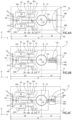
- Figure 9 shows a portion of a wafer 70 of semiconductor material, in particular silicon, wherein a plurality of dies 51 have been provided, each integrating a corresponding mirror tiltable structure 50 (according to the embodiment previously discussed with reference to Figure 7A ).
- dummy dies are highlighted, indicated by 72, interposed between the dies 51, in this case along the second horizontal axis y'.
- Figure 10 shows a respective wafer 70 of semiconductor material, in particular silicon, wherein a plurality of dies 51 have been provided, each integrating a corresponding mirror tiltable structure 50 (this time according to the embodiment previously discussed with reference to Figure 7B ).
- a corresponding mirror tiltable structure 50 this time according to the embodiment previously discussed with reference to Figure 7B .
- LT scribing lines, indicated by LT, non-parallel, in this case the absence of the aforementioned dummy dies 72 is highlighted, given the contiguous and adjacent arrangement of dies 51.
- the optoelectronic device 80 comprises a light source 82, for example of a laser type, for generating a light beam 83; the microelectromechanical mirror device 3, acting as a mirror module with biaxial projection and for receiving the light beam 83 and directing it towards a screen or display surface 85 (external and placed at a distance from the same optoelectronic device 80); a first driving circuit 86, for providing suitable control signals to the light source 82, for generation of the light beam 83, as a function of an image to be projected; a second driving circuit 88, for providing suitable control signals to the actuation structure of the microelectronic mirror device 3; and an interface 89, for receiving, from a control unit 90, in this case being external, for example included in the portable electronic apparatus 81, first control signals to control the first driving circuit 86, and second control signals to control the second driving circuit 88.
- a control unit 90 in this case being external, for example included in the portable electronic apparatus 81, first control signals to control
- the control unit 90 also receives, through the interface 89, a feedback signal, provided by the microelectromechanical mirror device 3, for a feedback control of the driving of the same tiltable structure 2.
- the described asymmetrical embodiment of the mirror tiltable structure 10 (3a) allows obtaining a reduced area occupation of the same mirror tiltable structure 10, in particular a reduction of the aforementioned first extension dimension d1 on the first side of the second axis B.
- This embodiment therefore allows avoiding clipping of the light projection, due to the close arrangement between the mirror tiltable structures 3a, 3b of a microelectromechanical mirror device 3 with biaxial projection, as described with reference to the prior art.
- the shaping of the die 51 of the mirror tiltable structure 50 (3b) and the resulting assembly with optimized volume occupation of the resulting microelectromechanical mirror device 3 is also advantageous.
- the present solution allows exploiting the advantages of the piezoelectric actuation (i.e., the use of reduced biasing voltages with a reduced energy consumption to obtain high displacements) and of the mirror actuation piezoresistive sensing, while having improved mechanical and electrical performance with respect to known solutions.
Applications Claiming Priority (1)
| Application Number | Priority Date | Filing Date | Title |
|---|---|---|---|
| IT202200012884 | 2022-06-17 |
Publications (1)
| Publication Number | Publication Date |
|---|---|
| EP4293409A1 true EP4293409A1 (de) | 2023-12-20 |
Family
ID=82943163
Family Applications (1)
| Application Number | Title | Priority Date | Filing Date |
|---|---|---|---|
| EP23177206.2A Pending EP4293409A1 (de) | 2022-06-17 | 2023-06-05 | Mikroelektromechanische spiegelvorrichtung mit piezoelektrischer betätigung und optimierter grösse |
Country Status (2)
| Country | Link |
|---|---|
| US (1) | US20230408808A1 (de) |
| EP (1) | EP4293409A1 (de) |
Citations (7)
| Publication number | Priority date | Publication date | Assignee | Title |
|---|---|---|---|---|
| US20100296147A1 (en) * | 2008-01-31 | 2010-11-25 | Jirou Terada | Optical reflection element |
| US20120092738A1 (en) * | 2010-10-18 | 2012-04-19 | Microvision, Inc. | Scanning Platform Having Asymmetric Flexures |
| US20140313558A1 (en) * | 2013-04-19 | 2014-10-23 | Microvision, Inc. | MEMS Device with Asymmetric Flexures |
| EP2980626A1 (de) * | 2014-07-29 | 2016-02-03 | Ricoh Company, Ltd. | Lichtablenker und vorrichtung mit dem lichtablenker |
| EP3666727A1 (de) | 2018-12-14 | 2020-06-17 | STMicroelectronics S.r.l. | Mikroelektromechanische vorrichtung mit einer durch piezoelektrische ansteuerung kippbaren struktur mit verbesserten mechanischen und elektrischen eigenschaften |
| US20200326532A1 (en) * | 2019-04-15 | 2020-10-15 | Microsoft Technology Licensing, Llc | Mems scanner |
| US20210356733A1 (en) * | 2020-05-12 | 2021-11-18 | Microsoft Technology Licensing, Llc | Microelectromechanical system (mems) scanner having a torsional beam flexure with variable width |
-
2023
- 2023-06-05 EP EP23177206.2A patent/EP4293409A1/de active Pending
- 2023-06-12 US US18/208,464 patent/US20230408808A1/en active Pending
Patent Citations (7)
| Publication number | Priority date | Publication date | Assignee | Title |
|---|---|---|---|---|
| US20100296147A1 (en) * | 2008-01-31 | 2010-11-25 | Jirou Terada | Optical reflection element |
| US20120092738A1 (en) * | 2010-10-18 | 2012-04-19 | Microvision, Inc. | Scanning Platform Having Asymmetric Flexures |
| US20140313558A1 (en) * | 2013-04-19 | 2014-10-23 | Microvision, Inc. | MEMS Device with Asymmetric Flexures |
| EP2980626A1 (de) * | 2014-07-29 | 2016-02-03 | Ricoh Company, Ltd. | Lichtablenker und vorrichtung mit dem lichtablenker |
| EP3666727A1 (de) | 2018-12-14 | 2020-06-17 | STMicroelectronics S.r.l. | Mikroelektromechanische vorrichtung mit einer durch piezoelektrische ansteuerung kippbaren struktur mit verbesserten mechanischen und elektrischen eigenschaften |
| US20200326532A1 (en) * | 2019-04-15 | 2020-10-15 | Microsoft Technology Licensing, Llc | Mems scanner |
| US20210356733A1 (en) * | 2020-05-12 | 2021-11-18 | Microsoft Technology Licensing, Llc | Microelectromechanical system (mems) scanner having a torsional beam flexure with variable width |
Also Published As
| Publication number | Publication date |
|---|---|
| US20230408808A1 (en) | 2023-12-21 |
Similar Documents
| Publication | Publication Date | Title |
|---|---|---|
| US11656539B2 (en) | Microelectromechanical device with a structure tiltable by piezoelectric actuation having improved mechanical and electrical characteristics | |
| US11933966B2 (en) | Resonant MEMS device having a tiltable, piezoelectrically controlled micromirror | |
| CN111717884A (zh) | 具有改善特性的压电致动双轴线谐振微机电反射镜结构 | |
| US20230249960A1 (en) | Micro-electro-mechanical device with a shock-protected tiltable structure | |
| JPWO2019176204A1 (ja) | 光走査装置およびその制御方法 | |
| US20200057298A1 (en) | Micromechanical device having a structure tiltable by a quasi-static piezoelectric actuation and having stiffening elements | |
| US11353694B2 (en) | Microelectromechanical mirror device with piezoelectric actuation, having an improved structure | |
| EP4242724A1 (de) | Biaxiale mikroelektromechanische spiegelvorrichtung mit piezoelektrischer betätigung | |
| EP4293409A1 (de) | Mikroelektromechanische spiegelvorrichtung mit piezoelektrischer betätigung und optimierter grösse | |
| US11086122B2 (en) | Microelectromechanical device having a structure tiltable through an actuation of the piezoelectric type | |
| CN217148569U (zh) | 微机电设备 | |
| CN117250749A (zh) | 具有压电致动和优化尺寸的微机电镜面设备 | |
| EP4082962A1 (de) | Mikroelektromechanische spiegelvorrichtung mit piezoelektrischer ansteuerung und verbessertem öffnungswinkel | |
| CN220467578U (zh) | 包括微机电镜设备的设备及微机电镜设备 | |
| CN217639747U (zh) | 微机电系统mems镜器件和便携式电子装置 | |
| US20240019688A1 (en) | Mems mirror device with piezoelectric actuation and manufacturing process thereof |
Legal Events
| Date | Code | Title | Description |
|---|---|---|---|
| PUAI | Public reference made under article 153(3) epc to a published international application that has entered the european phase |
Free format text: ORIGINAL CODE: 0009012 |
|
| STAA | Information on the status of an ep patent application or granted ep patent |
Free format text: STATUS: THE APPLICATION HAS BEEN PUBLISHED |
|
| AK | Designated contracting states |
Kind code of ref document: A1 Designated state(s): AL AT BE BG CH CY CZ DE DK EE ES FI FR GB GR HR HU IE IS IT LI LT LU LV MC ME MK MT NL NO PL PT RO RS SE SI SK SM TR |