EP4293294A1 - Method and device for controlling air conditioner - Google Patents
Method and device for controlling air conditioner Download PDFInfo
- Publication number
- EP4293294A1 EP4293294A1 EP21931171.9A EP21931171A EP4293294A1 EP 4293294 A1 EP4293294 A1 EP 4293294A1 EP 21931171 A EP21931171 A EP 21931171A EP 4293294 A1 EP4293294 A1 EP 4293294A1
- Authority
- EP
- European Patent Office
- Prior art keywords
- way valve
- air conditioner
- heat exchanger
- powered
- response
- Prior art date
- Legal status (The legal status is an assumption and is not a legal conclusion. Google has not performed a legal analysis and makes no representation as to the accuracy of the status listed.)
- Pending
Links
Images





Classifications
-
- F—MECHANICAL ENGINEERING; LIGHTING; HEATING; WEAPONS; BLASTING
- F24—HEATING; RANGES; VENTILATING
- F24F—AIR-CONDITIONING; AIR-HUMIDIFICATION; VENTILATION; USE OF AIR CURRENTS FOR SCREENING
- F24F11/00—Control or safety arrangements
- F24F11/62—Control or safety arrangements characterised by the type of control or by internal processing, e.g. using fuzzy logic, adaptive control or estimation of values
- F24F11/63—Electronic processing
- F24F11/64—Electronic processing using pre-stored data
-
- F—MECHANICAL ENGINEERING; LIGHTING; HEATING; WEAPONS; BLASTING
- F25—REFRIGERATION OR COOLING; COMBINED HEATING AND REFRIGERATION SYSTEMS; HEAT PUMP SYSTEMS; MANUFACTURE OR STORAGE OF ICE; LIQUEFACTION SOLIDIFICATION OF GASES
- F25B—REFRIGERATION MACHINES, PLANTS OR SYSTEMS; COMBINED HEATING AND REFRIGERATION SYSTEMS; HEAT PUMP SYSTEMS
- F25B47/00—Arrangements for preventing or removing deposits or corrosion, not provided for in another subclass
- F25B47/02—Defrosting cycles
-
- F—MECHANICAL ENGINEERING; LIGHTING; HEATING; WEAPONS; BLASTING
- F24—HEATING; RANGES; VENTILATING
- F24F—AIR-CONDITIONING; AIR-HUMIDIFICATION; VENTILATION; USE OF AIR CURRENTS FOR SCREENING
- F24F11/00—Control or safety arrangements
- F24F11/62—Control or safety arrangements characterised by the type of control or by internal processing, e.g. using fuzzy logic, adaptive control or estimation of values
- F24F11/63—Electronic processing
- F24F11/65—Electronic processing for selecting an operating mode
-
- F—MECHANICAL ENGINEERING; LIGHTING; HEATING; WEAPONS; BLASTING
- F24—HEATING; RANGES; VENTILATING
- F24F—AIR-CONDITIONING; AIR-HUMIDIFICATION; VENTILATION; USE OF AIR CURRENTS FOR SCREENING
- F24F11/00—Control or safety arrangements
- F24F11/70—Control systems characterised by their outputs; Constructional details thereof
-
- F—MECHANICAL ENGINEERING; LIGHTING; HEATING; WEAPONS; BLASTING
- F24—HEATING; RANGES; VENTILATING
- F24F—AIR-CONDITIONING; AIR-HUMIDIFICATION; VENTILATION; USE OF AIR CURRENTS FOR SCREENING
- F24F11/00—Control or safety arrangements
- F24F11/70—Control systems characterised by their outputs; Constructional details thereof
- F24F11/80—Control systems characterised by their outputs; Constructional details thereof for controlling the temperature of the supplied air
- F24F11/83—Control systems characterised by their outputs; Constructional details thereof for controlling the temperature of the supplied air by controlling the supply of heat-exchange fluids to heat-exchangers
- F24F11/84—Control systems characterised by their outputs; Constructional details thereof for controlling the temperature of the supplied air by controlling the supply of heat-exchange fluids to heat-exchangers using valves
-
- F—MECHANICAL ENGINEERING; LIGHTING; HEATING; WEAPONS; BLASTING
- F25—REFRIGERATION OR COOLING; COMBINED HEATING AND REFRIGERATION SYSTEMS; HEAT PUMP SYSTEMS; MANUFACTURE OR STORAGE OF ICE; LIQUEFACTION SOLIDIFICATION OF GASES
- F25B—REFRIGERATION MACHINES, PLANTS OR SYSTEMS; COMBINED HEATING AND REFRIGERATION SYSTEMS; HEAT PUMP SYSTEMS
- F25B13/00—Compression machines, plants or systems, with reversible cycle
-
- F—MECHANICAL ENGINEERING; LIGHTING; HEATING; WEAPONS; BLASTING
- F25—REFRIGERATION OR COOLING; COMBINED HEATING AND REFRIGERATION SYSTEMS; HEAT PUMP SYSTEMS; MANUFACTURE OR STORAGE OF ICE; LIQUEFACTION SOLIDIFICATION OF GASES
- F25B—REFRIGERATION MACHINES, PLANTS OR SYSTEMS; COMBINED HEATING AND REFRIGERATION SYSTEMS; HEAT PUMP SYSTEMS
- F25B41/00—Fluid-circulation arrangements
- F25B41/20—Disposition of valves, e.g. of on-off valves or flow control valves
-
- F—MECHANICAL ENGINEERING; LIGHTING; HEATING; WEAPONS; BLASTING
- F25—REFRIGERATION OR COOLING; COMBINED HEATING AND REFRIGERATION SYSTEMS; HEAT PUMP SYSTEMS; MANUFACTURE OR STORAGE OF ICE; LIQUEFACTION SOLIDIFICATION OF GASES
- F25B—REFRIGERATION MACHINES, PLANTS OR SYSTEMS; COMBINED HEATING AND REFRIGERATION SYSTEMS; HEAT PUMP SYSTEMS
- F25B41/00—Fluid-circulation arrangements
- F25B41/20—Disposition of valves, e.g. of on-off valves or flow control valves
- F25B41/26—Disposition of valves, e.g. of on-off valves or flow control valves of fluid flow reversing valves
-
- F—MECHANICAL ENGINEERING; LIGHTING; HEATING; WEAPONS; BLASTING
- F25—REFRIGERATION OR COOLING; COMBINED HEATING AND REFRIGERATION SYSTEMS; HEAT PUMP SYSTEMS; MANUFACTURE OR STORAGE OF ICE; LIQUEFACTION SOLIDIFICATION OF GASES
- F25B—REFRIGERATION MACHINES, PLANTS OR SYSTEMS; COMBINED HEATING AND REFRIGERATION SYSTEMS; HEAT PUMP SYSTEMS
- F25B2313/00—Compression machines, plants or systems with reversible cycle not otherwise provided for
- F25B2313/021—Indoor unit or outdoor unit with auxiliary heat exchanger not forming part of the indoor or outdoor unit
- F25B2313/0211—Indoor unit or outdoor unit with auxiliary heat exchanger not forming part of the indoor or outdoor unit the auxiliary heat exchanger being only used during defrosting
-
- F—MECHANICAL ENGINEERING; LIGHTING; HEATING; WEAPONS; BLASTING
- F25—REFRIGERATION OR COOLING; COMBINED HEATING AND REFRIGERATION SYSTEMS; HEAT PUMP SYSTEMS; MANUFACTURE OR STORAGE OF ICE; LIQUEFACTION SOLIDIFICATION OF GASES
- F25B—REFRIGERATION MACHINES, PLANTS OR SYSTEMS; COMBINED HEATING AND REFRIGERATION SYSTEMS; HEAT PUMP SYSTEMS
- F25B2313/00—Compression machines, plants or systems with reversible cycle not otherwise provided for
- F25B2313/027—Compression machines, plants or systems with reversible cycle not otherwise provided for characterised by the reversing means
- F25B2313/02742—Compression machines, plants or systems with reversible cycle not otherwise provided for characterised by the reversing means using two four-way valves
-
- F—MECHANICAL ENGINEERING; LIGHTING; HEATING; WEAPONS; BLASTING
- F25—REFRIGERATION OR COOLING; COMBINED HEATING AND REFRIGERATION SYSTEMS; HEAT PUMP SYSTEMS; MANUFACTURE OR STORAGE OF ICE; LIQUEFACTION SOLIDIFICATION OF GASES
- F25B—REFRIGERATION MACHINES, PLANTS OR SYSTEMS; COMBINED HEATING AND REFRIGERATION SYSTEMS; HEAT PUMP SYSTEMS
- F25B2313/00—Compression machines, plants or systems with reversible cycle not otherwise provided for
- F25B2313/029—Control issues
- F25B2313/0292—Control issues related to reversing valves
-
- F—MECHANICAL ENGINEERING; LIGHTING; HEATING; WEAPONS; BLASTING
- F25—REFRIGERATION OR COOLING; COMBINED HEATING AND REFRIGERATION SYSTEMS; HEAT PUMP SYSTEMS; MANUFACTURE OR STORAGE OF ICE; LIQUEFACTION SOLIDIFICATION OF GASES
- F25B—REFRIGERATION MACHINES, PLANTS OR SYSTEMS; COMBINED HEATING AND REFRIGERATION SYSTEMS; HEAT PUMP SYSTEMS
- F25B2347/00—Details for preventing or removing deposits or corrosion
- F25B2347/02—Details of defrosting cycles
-
- F—MECHANICAL ENGINEERING; LIGHTING; HEATING; WEAPONS; BLASTING
- F25—REFRIGERATION OR COOLING; COMBINED HEATING AND REFRIGERATION SYSTEMS; HEAT PUMP SYSTEMS; MANUFACTURE OR STORAGE OF ICE; LIQUEFACTION SOLIDIFICATION OF GASES
- F25B—REFRIGERATION MACHINES, PLANTS OR SYSTEMS; COMBINED HEATING AND REFRIGERATION SYSTEMS; HEAT PUMP SYSTEMS
- F25B2400/00—Component parts or details not otherwise provided for in this subclass
- F25B2400/04—Refrigeration circuit bypassing means
-
- F—MECHANICAL ENGINEERING; LIGHTING; HEATING; WEAPONS; BLASTING
- F25—REFRIGERATION OR COOLING; COMBINED HEATING AND REFRIGERATION SYSTEMS; HEAT PUMP SYSTEMS; MANUFACTURE OR STORAGE OF ICE; LIQUEFACTION SOLIDIFICATION OF GASES
- F25B—REFRIGERATION MACHINES, PLANTS OR SYSTEMS; COMBINED HEATING AND REFRIGERATION SYSTEMS; HEAT PUMP SYSTEMS
- F25B2400/00—Component parts or details not otherwise provided for in this subclass
- F25B2400/24—Thermal storage element
Definitions
- the present disclosure relates to the field of an air conditioner technology, particularly relates to a method and device for controlling an air conditioner, an air conditioner, an electronic device and a computer readable storage medium.
- an air conditioner has also been on an increasing comfort requirement.
- an outdoor unit to frost in a heating mode serving as an evaporator; while during a defrosting process, an indoor unit is converted to serve as the evaporator and the outdoor unit is converted to serve as a condenser to absorb heat from indoor for defrosting the outdoor unit, resulting in poor heating performance of the indoor unit, thus adversely affecting the user's experience.
- the present disclosure aims to solve at least one of the technical problems in the related art to a certain degree.
- an object of the present disclosure is to propose a method for controlling an air conditioner, which identifies an operation mode of the air conditioner; controls the first four-way valve and the second four-way valve both to be powered on in response to the operation mode of the air conditioner being a heating mode; and controls the first four-way valve to be powered off and the second four-way valve to be powered on in response to the operation mode of the air conditioner being a defrosting mode.
- the outdoor heat exchanger and the indoor heat exchanger each serve as a condenser, while the heat storage heat exchanger serves as an evaporator, such that heat is absorbed from the heat storage heat exchanger for defrosting the outdoor heat exchanger without adversely affecting the heating performance of the indoor heat exchanger, thereby improving the air conditioner for comfort and user's experience.
- a second object of the present disclosure is to propose a device for controlling an air conditioner.
- a third object of the present disclosure is to provide an air conditioner.
- a fourth object of the present disclosure is to provide an electronic device.
- a fifth object of the present disclosure is to provide a computer readable storage medium.
- the present disclosure provides in an embodiment a method for controlling an air conditioner, wherein the air conditioner includes an outdoor heat exchanger, an indoor heat exchanger, a heat storage heat exchanger, a compressor, a four-way valve assembly, and a throttling assembly, the outdoor heat exchanger and the indoor heat exchanger are connected to a bypass through a first pipeline, the outdoor heat exchanger is connected to the compressor through a second pipeline, the indoor heat exchanger is connected to the compressor through a third pipeline, wherein the heat storage heat exchanger is arranged at the bypass, the throttling assembly is arranged at the bypass, the four-way valve assembly includes a first four-way valve and a second four-way valve, the first four-way valve is arranged at the second pipeline, the second four-way valve is arranged at the third pipeline, the method for controlling the air conditioner includes: identifying an operation mode of the air conditioner; controlling the first four-way valve and the second four-way valve both to be powered on in response to the operation mode of the
- the method for controlling the air conditioner identifies the operation mode of the air conditioner; controls the first four-way valve and the second four-way valve both to be powered on in response to the operation mode of the air conditioner being the heating mode; and controls the first four-way valve to be powered off and the second four-way valve to be powered on in response to the operation mode of the air conditioner being the defrosting mode.
- the outdoor heat exchanger and the indoor heat exchanger each serve as a condenser, while the heat storage heat exchanger serves as an evaporator, such that heat is absorbed from the heat storage heat exchanger for defrosting the outdoor heat exchanger without adversely affecting the heating performance of the indoor heat exchanger, thereby improving the air conditioner for comfort and user's experience.
- the method for controlling the air conditioner proposed according to the above embodiment of the present disclosure may further include the following additional technical features.
- the method further includes: controlling the first four-way valve and the second four-way valve both to be powered on, in response to identifying that a pipe-wall temperature of the outdoor heat exchanger is higher than or equal to a first preset temperature and/or that a defrosting duration reaches a first preset duration.
- the method further includes: determining whether the air conditioner is in a target operation state, wherein the target operation state includes a heating target operation state and a cooling target operation state; and controlling the throttling assembly to switch on in response to the air conditioner being in the target operation state, or controlling the throttling assembly to switch off in response to the air conditioner being not in the target operation state.
- determining whether the air conditioner is in the target operation state includes: determining that the air conditioner is in the target operation state, in response to identifying that the air conditioner is of a heating capacity demand parameter or a cooling capacity demand parameter lower than or equal to a first preset threshold for a second preset duration; or determining that the air conditioner is out of the target operation state, in response to identifying that the air conditioner is of a heating capacity demand parameter or a cooling capacity demand parameter greater than or equal to a second preset threshold for a third preset duration.
- the air conditioner includes a plurality of the indoor heat exchangers, and determining whether the air conditioner is in the target operation state further includes: based on that the operation mode of the air conditioner is a mixed mode, wherein the mixed mode includes the heating mode for at least one of the indoor heat exchangers and a cooling mode for at least one of the indoor heat exchangers, acquiring a heating capacity demand parameter and a cooling capacity demand parameter; determining that the air conditioner is in the heating target operation state, in response to identifying that the heating capacity demand parameter is lower than or equal to the cooling capacity demand parameter, or determining that the air conditioner is in the cooling target operation state, in response to identifying that the heating capacity demand parameter is greater than the cooling capacity demand parameter.
- the method prior to controlling the throttling assembly to switch on, the method further includes: identifying that a duration during which a pipe-wall temperature of the indoor heat exchanger is higher than or equal to a second preset temperature reaches a fourth preset duration in response to the air conditioner being in the heating target operation state; or identifying that a duration during which a pipe-wall temperature of the indoor heat exchanger is lower than or equal to a third preset temperature reaches a fifth preset duration in response to the air conditioner being in the cooling target operation state.
- the method further includes: based on that the air conditioner is in the heating target operation state, controlling the first four-way valve to be powered off, in response to identifying that a duration during which an outlet pipe-wall temperature of the heat storage heat exchanger is greater than or equal to a fourth preset temperature reaches a sixth preset duration; and controlling the first four-way valve to be powered on, and returning to perform the step of determining whether the air conditioner is in the target operation state and subsequent steps thereof, in response to identifying that a duration during which an inlet pipe-wall temperature of the heat storage heat exchanger is lower than or equal to a fifth preset temperature and/or that a duration during which the first four-way valve is powered off reaches a seventh preset duration.
- the method further includes: based on that the air conditioner is in the cooling target operation state, controlling the first four-way valve to be powered on, in response to identifying that a duration during which an outlet pipe-wall temperature of the heat storage heat exchanger is lower than or equal to a sixth preset temperature reaches an eighth preset duration; and controlling the first four-way valve to be powered off, and returning to the step of determining whether the air conditioner is in the target operation state and subsequent steps thereof, in response to identifying that a duration during which an inlet pipe-wall temperature of the heat storage heat exchanger is greater than or equal to a seventh preset temperature and/or that a duration during which the first four-way valve is powered on reaches a ninth preset duration.
- the four-way valve assembly further includes a third four-way valve arranged at the bypass; the method further includes: controlling the third four-way valve to be powered off in response to the operation mode of the air conditioner being the heating mode; and controlling the third four-way valve to be powered on in response to the operation mode of the air conditioner being the defrosting mode.
- the method further includes: controlling the first four-way valve and the second four-way valve both to be powered off and the third four-way valve to be powered on, in response to the operation mode of the air conditioner being the cooling mode.
- the present disclosure provides in an embodiment a device for controlling an air conditioner
- the air conditioner includes an outdoor heat exchanger, an indoor heat exchanger, a heat storage heat exchanger, a compressor, a four-way valve assembly, and a throttling assembly
- the outdoor heat exchanger and the indoor heat exchanger are connected to a bypass through a first pipeline
- the outdoor heat exchanger is connected to the compressor through a second pipeline
- the indoor heat exchanger is connected to the compressor through a third pipeline
- the heat storage heat exchanger is arranged at the bypass
- the throttling assembly is arranged at the bypass
- the four-way valve assembly includes a first four-way valve and a second four-way valve
- the first four-way valve is arranged at the second pipeline
- the second four-way valve is arranged at the third pipeline
- the device for controlling the air conditioner includes: an identifying module, configured to identify an operation mode of the air conditioner; and a responding module, configured to control the first four-way valve and the second four-way valve both
- the device for controlling the air conditioner identifies the operation mode of the air conditioner; controls the first four-way valve and the second four-way valve both to be powered on in response to the operation mode of the air conditioner being the heating mode; and controls the first four-way valve to be powered off and the second four-way valve to be powered on in response to the operation mode of the air conditioner being the defrosting mode.
- the outdoor heat exchanger and the indoor heat exchanger each serve as a condenser, while the heat storage heat exchanger serves as an evaporator, such that heat is absorbed from the heat storage heat exchanger for defrosting the outdoor heat exchanger without adversely affecting the heating performance of the indoor heat exchanger, thereby improving the air conditioner for comfort and user's experience.
- the device for controlling the air conditioner proposed according to the above embodiment of the present disclosure may further include the following additional technical features.
- the device for controlling the air conditioner further includes a control module, wherein after the first four-way valve is controlled to be powered off and the second four-way valve is controlled to be powered on, an identifying module is configured to control the first four-way valve and the second four-way valve both to be powered on, in response to identifying that a pipe-wall temperature of the outdoor heat exchanger is higher than or equal to a first preset temperature and/or that a defrosting duration reaches a first preset duration.
- the device for controlling the air conditioner further includes an identifying module, configured to determine whether the air conditioner is in a target operation state, wherein the target operation state includes a heating target operation state and a cooling target operation state; and the responding module is further configured to control the throttling assembly to switch on in response to the air conditioner being in the target operation state, or control the throttling assembly to switch off in response to the air conditioner being not in the target operation state.
- the determining module is specifically configured to determine that the air conditioner is in the target operation state, in response to identifying that a duration during which a heating capacity demand parameter or a cooling capacity demand parameter of the air conditioner is lower than or equal to a first preset threshold reaches a first preset threshold for a second preset duration; or determine that the air conditioner is not in the target operation state, in response to identifying that a duration during which a heating capacity demand parameter or a cooling capacity demand parameter of the air conditioner is greater than or equal to a second preset threshold reaches a third preset duration.
- the air conditioner includes a plurality of the indoor heat exchangers
- the determining module is specifically configured to, based on that the operation mode of the air conditioner is a mixed mode, wherein the mixed mode includes the heating mode for at least one of the indoor heat exchangers and a cooling mode for at least one of the indoor heat exchangers, acquire a heating capacity demand parameter and a cooling capacity demand parameter; determine that the air conditioner is in the heating target operation state, in response to identifying that the heating capacity demand parameter is lower than or equal to the cooling capacity demand parameter, or determine that the air conditioner is in the cooling target operation state, in response to identifying that the heating capacity demand parameter is greater than the cooling capacity demand parameter.
- the responding module is further configured to identify that a duration during which a pipe-wall temperature of the indoor heat exchanger is higher than or equal to a second preset temperature reaches a fourth preset duration in response to the air conditioner being in the heating target operation state; or identify that a duration during which a pipe-wall temperature of the indoor heat exchanger is lower than or equal to a third preset temperature reaches a fifth preset duration in response to the air conditioner being in the cooling target operation state.
- the responding module is further configured to, based on that the air conditioner is in the heating target operation state, control the first four-way valve to be powered off, in response to identifying that a duration during which an outlet pipe-wall temperature of the heat storage heat exchanger is greater than or equal to a fourth preset temperature reaches a sixth preset duration; and control the first four-way valve to be powered on, and returning to perform the step of determining whether the air conditioner) is in the target operation state and subsequent steps thereof, in response to identifying that a duration during which an inlet pipe-wall temperature of the heat storage heat exchanger is lower than or equal to a fifth preset temperature and/or that a duration during which the first four-way valve is powered off reaches a seventh preset duration.
- the responding module is further configured to, based on that the air conditioner is in the cooling target operation state, control the first four-way valve to be powered on, in response to identifying that a duration during which an outlet pipe-wall temperature of the heat storage heat exchanger is lower than or equal to a sixth preset temperature reaches an eighth preset duration; and control the first four-way valve to be powered off, and returning to the step of determining whether the air conditioner is in the target operation state and subsequent steps thereof, in response to identifying that a duration during which an inlet pipe-wall temperature of the heat storage heat exchanger is greater than or equal to a seventh preset temperature and/or that a duration during which the first four-way valve is powered on reaches a ninth preset duration.
- the four-way valve assembly further includes a third four-way valve arranged at the bypass; and the responding module is further configured to control the third four-way valve to be powered off in response to the operation mode of the air conditioner being the heating mode; and control the third four-way valve to be powered on in response to the operation mode of the air conditioner being the defrosting mode.
- the responding module is further configured to control the first four-way valve and the second four-way valve both to be powered off and the third four-way valve to be powered on, in response to the operation mode of the air conditioner being the cooling mode.
- the present disclosure provides in an embodiment an air conditioner, including: an outdoor heat exchanger, an indoor heat exchanger, a heat storage heat exchanger, a compressor, a four-way valve assembly, and a throttling assembly, wherein the outdoor heat exchanger and the indoor heat exchanger are connected to a bypass through a first pipeline, the outdoor heat exchanger is connected to the compressor through a second pipeline, the indoor heat exchanger is connected to the compressor through a third pipeline, wherein the heat storage heat exchanger is arranged at the bypass, the throttling assembly is arranged at the bypass, the four-way valve assembly includes a first four-way valve and a second four-way valve, the first four-way valve is arranged at the second pipeline, the second four-way valve is arranged at the third pipeline; and a device for controlling an air conditioner as described in embodiments in the second aspect of the present disclosure.
- the air conditioner identifies the operation mode of the air conditioner; controls the first four-way valve and the second four-way valve both to be powered on in response to the operation mode of the air conditioner being the heating mode; and controls the first four-way valve to be powered off and the second four-way valve to be powered on in response to the operation mode of the air conditioner being the defrosting mode.
- the outdoor heat exchanger and the indoor heat exchanger each serve as a condenser, while the heat storage heat exchanger serves as an evaporator, such that heat is absorbed from the heat storage heat exchanger for defrosting the outdoor heat exchanger without adversely affecting the heating performance of the indoor heat exchanger, thereby improving the air conditioner for comfort and user's experience.
- the air conditioner proposed according to the above embodiment of the present disclosure may further include the following additional technical feature.
- the four-way valve assembly further includes a third four-way valve arranged at the bypass.
- the present disclosure provides in an embodiment an electronic device, including a memory and a processor, wherein the processor runs a program corresponding to an executable program code by reading the executable program code stored in the memory, to implement a method for controlling an air conditioner as described in embodiments of the first aspect of the present disclosure.
- the electronic device by means of the processor executing the computer program stored in the memory, identifies the operation mode of the air conditioner; controls the first four-way valve and the second four-way valve both to be powered on in response to the operation mode of the air conditioner being the heating mode; and controls the first four-way valve to be powered off and the second four-way valve to be powered on in response to the operation mode of the air conditioner being the defrosting mode.
- the outdoor heat exchanger and the indoor heat exchanger each serve as a condenser, while the heat storage heat exchanger serves as an evaporator, such that heat is absorbed from the heat storage heat exchanger for defrosting the outdoor heat exchanger without adversely affecting the heating performance of the indoor heat exchanger, thereby improving the air conditioner for comfort and user's experience.
- the present disclosure provides in an embodiment a computer readable storage medium having stored therein a computer program that, when executed by a processor, implements a method for controlling an air conditioner as described in embodiments of the first aspect of the present disclosure.
- the computer readable storage medium by having stored therein the computer program that is executed by the processor, identifies the operation mode of the air conditioner; controls the first four-way valve and the second four-way valve both to be powered on in response to the operation mode of the air conditioner being the heating mode; and controls the first four-way valve to be powered off and the second four-way valve to be powered on in response to the operation mode of the air conditioner being the defrosting mode.
- the outdoor heat exchanger and the indoor heat exchanger each serve as a condenser, while the heat storage heat exchanger serves as an evaporator, such that heat is absorbed from the heat storage heat exchanger for defrosting the outdoor heat exchanger without adversely affecting the heating performance of the indoor heat exchanger, thereby improving the air conditioner for comfort and user's experience.
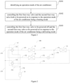
- Figure 1 is a flow chart showing a method for controlling an air conditioner according to an embodiment of the present disclosure.
- the air conditioner includes the outdoor heat exchanger 11, the indoor heat exchanger 12, the heat storage heat exchanger 13, the compressor 14, the four-way valve assembly 15, and the throttling assembly 16. It should note that the air conditioner illustrated in Figure 2 is merely an example of the air conditioner in an embodiment of the present disclosure, rather than limitation to the air conditioner in an embodiment of the present disclosure.
- the outdoor heat exchanger 11 and the indoor heat exchanger 12 are connected to a bypass 172 through a first pipeline 171; the outdoor heat exchanger 11 is connected to the compressor 14 through the second pipeline 173; and the indoor heat exchanger 12 is connected to the compressor 14 through the third pipeline 174.
- the heat storage heat exchanger 13 is arranged at the bypass 172, and the bypass 172 is provided with the throttling assembly 16.
- the four-way valve assembly 15 includes the first four-way valve 151 and the second four-way valve 152.
- the first four-way valve 151 is arranged at the second pipeline 173; and the second four-way valve 152 is arranged at the third pipeline 174.
- the first pipeline 171 is provided with the throttling assembly 16.
- first four-way valve 151 and the second four-way valve 152 each may be an electronic expansion valve.
- the method for controlling the air conditioner includes the following steps.
- the operation mode of the air conditioner may be set according to an actual situation.
- a user may set the operation mode of the air conditioner in a flexible way.
- the use may set the operation mode of the air conditioner by a remote controller, an Application (APP) for the air conditioner in a mobile terminal, or a control panel on a body of the air conditioner, or through a non-contact approach such as a language and a gesture.
- APP Application
- APP Application
- the first four-way valve and the second four-way valve both are controlled to be powered on.
- the first four-way valve 151 and the second four-way valve 152 both are controlled to be powered on.
- the first four-way valve 151 is controlled to be powered on, enabling the pipeline between the interface A and the interface B of the first four-way valve 151 to be connected and the pipeline between the interface C and the interface D of the first four-way valve 151 to be connected, while the pipeline between the interface A and the interface D of the first four-way valve 151 to be disconnected and the pipeline between the interface B and the interface C of the first four-way valve 151 to be disconnected.
- the second four-way valve 152 is controlled to be powered on, enabling the pipeline between the interface A and the interface D of the second four-way valve 152 to be connected and the pipeline between the interface B and the interface C of the second four-way valve 152 to be connected, while the pipeline between the interface A and the interface B of the second four-way valve 152 to be disconnected and the pipeline between the interface C and the interface D of the second four-way valve 152 to be disconnected.
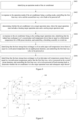
- Figure 3 shows a refrigerant flow direction in the air conditioner with the above-described connections, where a portion of a high-temperature and high-pressure refrigerant discharged from the compressor 14 enters the indoor heat exchanger 12 for heat release and condensation through the third pipeline 174, and the pipeline between the interface B and the interface C of the second four-way valve 152; another portion of the high-temperature and high-pressure refrigerant discharged from the compressor 14 enters the heat storage heat exchanger 13 for heat release and condensation through the pipeline between the interface C and the interface D of the first four-way valve 151 and the bypass 172, followed by throttling and depressurizing through the throttling assembly 16; and the refrigerant enters the outdoor heat exchanger 11 for heat absorption and evaporation, and returns back to the compressor 14 through the pipeline between the interface A and the interface B of the first four-way valve 151 and the second pipeline 173.
- the outdoor heat exchanger 11 serves as an evaporator
- the indoor heat exchanger 12 and the heat storage heat exchanger 13 each serve as a condenser.
- the heat storage heat exchanger 13 is used to store heat.
- the first four-way valve is controlled to be powered off, and the second four-way valve is controlled to be powered on.
- the first four-way valve 151 in response to the operation mode of the air conditioner being the defrosting mode, is controlled to be powered off, and the second four-way valve 152 is controlled to be powered on.
- the first four-way valve 151 is controlled to be powered off, enabling the pipeline between the interface A and the interface D of the first four-way valve 151 to be connected and the pipeline between the interface B and the interface C of the first four-way valve 151 to be connected, while the pipeline between the interface A and the interface B of the first four-way valve 151 to be disconnected and the pipeline between the interface C and the interface D of the first four-way valve 151 to be disconnected.
- Figure 4 shows a refrigerant flow direction in the air conditioner with the above-described connections, where a portion of a high-temperature and high-pressure refrigerant discharged from the compressor 14 enters the indoor heat exchanger 12 for heat release and condensation through the third pipeline 174, and the pipeline between the interface B and the interface C of the second four-way valve 152; another portion of the high-temperature and high-pressure refrigerant discharged from the compressor 14 enters the outdoor heat exchanger 11 for heat release and condensation through the pipeline between the interface B and the interface C of the first four-way valve 151, and the second pipeline 173; the refrigerant is throttled and depressurized through the throttling assembly 16, before enters the heat storage heat exchanger 13 for heat absorption and evaporation, and returns back to the compressor 14 through the bypass 172, the pipeline between the interface A and the interface D of the first four-way valve 151 and the second pipeline 173.
- the outdoor heat exchanger 11 and the indoor exchanger 12 each serve as a condenser, and the heat storage heat exchanger 13 serves as an evaporator.
- the outdoor heat exchanger 11 is converted from serving as the evaporator to serving as the condenser
- the indoor heat exchanger 12 continues serving as the condenser
- the heat storage heat exchanger 13 is converted from serving as the condenser to serving the evaporator, such that the heat is absorbed from the heat storage heat exchanger 13 for defrosting the outdoor heat exchanger 11 without adversely affecting the heating performance of the indoor heat exchanger 12, thereby improving the air conditioner for comfort and user's experience.
- the method for controlling the air conditioner identifies the operation mode of the air conditioner; controls the first four-way valve and the second four-way valve both to be powered on in response to the operation mode of the air conditioner being the heating mode; and controls the first four-way valve to be powered off and the second four-way valve to be powered on in response to the operation mode of the air conditioner being the defrosting mode.
- the outdoor heat exchanger and the indoor heat exchanger each serve as the condenser, while the heat storage heat exchanger serves as the evaporator, such that heat is absorbed from the heat storage heat exchanger for defrosting the outdoor heat exchanger without adversely affecting the heating performance of the indoor heat exchanger, thereby improving the air conditioner for comfort and user's experience.
- the method further includes: controlling the first four-way valve and the second four-way valve both to be powered on, in response to identifying that a pipe-wall temperature of the outdoor heat exchanger is higher than or equal to a first preset temperature and/or that a defrosting duration reaches a first preset duration.
- identifying that a pipe-wall temperature of the outdoor heat exchanger higher than or equal to the first preset temperature and/or that the defrosting duration reaches the first preset duration indicates that the pipe-wall temperature of the outdoor heat exchanger is relative high and/or that the defrosting duration is relative long at this time. Accordingly, it is determined that a criteria to finish defrosting is met in this circumstance, thus the first four-way valve and the second four-way valve both are controlled to be powered on, enabling the operation mode of the air conditioner to change from the defrosting mode to the heating mode.
- the first preset temperature and the first preset duration each may be set according to an actual situation.
- the first preset temperature may be set as 15°C and the first preset duration may be set as 10 minutes.
- the method further includes S201 and S202.
- the air conditioner is in a target operation state, where the target operation state includes a heating target operation state and a cooling target operation state.
- the air conditioner is in the target operation state, where the target operation state includes the heating target operation state and the cooling target operation state. It should note that the target operation state refers to an operation state under a low load.
- determining whether the air conditioner is in the target operation state may include the following two possible implementing approaches.
- Approach 1 in response to identifying that the air conditioner is of a heating capacity demand parameter (Nh) or a cooling capacity demand parameter (Nc) lower than or equal to a first preset threshold for a second preset duration, it is determined that the air conditioner is in the target operation state; or in response to identifying that the air conditioner is of a heating capacity demand parameter or a cooling capacity demand parameter greater than or equal to a second preset threshold for a third preset duration, it is determined that the air conditioner is not in the target operation state.
- Nh heating capacity demand parameter
- Nc cooling capacity demand parameter
- the heating capacity demand parameter or the cooling capacity demand parameter of the air conditioner may be used to characterize a load of the air conditioner. The smaller the heating capacity demand parameter or the cooling capacity demand parameter of the air conditioner, the lower the load of the air conditioner.
- Identifying that the air conditioner is of the heating capacity demand parameter or the cooling capacity demand parameter lower than or equal to the first preset threshold for the second preset duration indicates that the heating capacity demand parameter or the cooling capacity demand parameter of the air conditioner is relative low for a relative long time period at this time. Accordingly, it is determined that the air conditioner is in the target operation state.
- identifying that the air conditioner is of the heating capacity demand parameter or the cooling capacity demand parameter greater than or equal to the second preset threshold for the third preset duration indicates that the heating capacity demand parameter or the cooling capacity demand parameter of the air conditioner is relative high for a relative long time period at this time. Accordingly, it is determined that the air conditioner is out of the target operation state.
- the first preset threshold, the second preset threshold, the second preset duration, and the third preset duration each may be set according to an actual situation, which is not further limited here.
- the air conditioner includes a plurality of the indoor heat exchangers
- the mixed mode includes the heating mode for at least one of the indoor heat exchangers and a cooling mode for at least one of the indoor heat exchangers
- a heating capacity demand parameter and a cooling capacity demand parameter are acquired; and in response to identifying that the heating capacity demand parameter is lower than or equal to the cooling capacity demand parameter, it is determined that the air conditioner is in the heating target operation state; alternatively, in response to identifying that the heating capacity demand parameter is greater than the cooling capacity demand parameter, it is determined that the air conditioner is in the cooling target operation state.
- the number of the indoor heat exchangers is 2.
- the indoor heat exchangers each may be connected with a switching assembly (not shown in the Figure).
- Figure 6 is merely an example of the air conditioner in an embodiment of the present disclosure, rather than limitation to the air conditioner in an embodiment of the present disclosure.
- acquiring the heating capacity demand parameter may include acquiring the heating capacity demand parameter of the indoor heat exchanger in the operation mode being the heating mode; and accordingly, acquiring the cooling capacity demand parameter may include acquiring the cooling capacity demand parameter of the indoor heat exchanger in the operation mode being the cooling mode.
- heating capacity demand parameter indicates that the heating capacity demand parameter is relative low, and it is then determined that the air conditioner is in the heating target operation state; alternatively, identifying that the heating capacity demand parameter is greater than the cooling capacity demand parameter indicates that the cooling capacity demand parameter is relative low, and it is then determined that the air conditioner is in the cooling target operation state.
- the throttling assembly in response to the air conditioner being in the target operation state, the throttling assembly is controlled to switch on; or in response to the air conditioner being out of the target operation state, the throttling assembly is controlled to switch off.
- the throttling assembly in response to the air conditioner being in the target operation state, is controlled to switch on, enabling the bypass to be connected, allowing the refrigerant to enter the heat storage heat exchanger, such that the heat storage heat exchanger is used to store heat in this circumstance, thereby adjusting the load of the air conditioner by the heat storage heat exchanger, assisting in avoiding the air conditioner from being in the operation state under the low load for a long time period, thus improving operation reliability of the air conditioner.
- the throttling assembly in response to the air conditioner being out of the target operation state, the throttling assembly is controlled to switch off, enabling the bypass to be disconnected, such that the refrigerant cannot enter the heat storage heat exchanger and thus the heat storage heat exchanger is not used to store heat in this circumstance. Accordingly, the load of the air conditioner cannot be adjusted by the heat storage heat exchanger in this circumstance
- the method controls the throttling assembly to switch on or off according to whether the air conditioner is in the target operation state.
- the throttling assembly is controlled to switch on, thereby adjusting the load of the air conditioner by the heat storage heat exchanger, assisting in avoiding the air conditioner from being in the operation state under the low load for a long time period, thus improving operation reliability of the air conditioner.
- the method for controlling the air conditioner in another embodiment of the present disclosure includes the following steps.
- the first four-way valve and the second four-way valve both are controlled to be powered on.
- the air conditioner is in a target operation state, where the target operation state includes a heating target operation state and a cooling target operation state.
- the throttling assembly is controlled to be switched on, in response to identifying that the indoor heat exchanger is of a pipe-wall temperature higher than or equal to a second preset temperature for a fourth preset duration.
- the throttling assembly in response to identifying that the indoor heat exchanger is of the pipe-wall temperature higher than or equal to the second preset temperature for the fourth preset duration, indicating that the pipe-wall temperature of the indoor heat exchanger is relative high for a relative long time period, the throttling assembly is controlled to switch on, enabling the bypass to be connected, allowing the refrigerant to enter the heat storage heat exchanger for heat release and condensation, where the heat storage heat exchanger serves as a condenser for storing heat in this circumstance.
- the second preset temperature and the fourth preset duration each may be set according to an actual situation.
- the second preset temperature may be set as 58°C and the fourth preset duration may be set as 8 minutes.
- the first four-way valve is controlled to be powered off.
- the first four-way valve is controlled to be powered off.
- the refrigerant flow direction in the air conditioner in this circumstance is illustrated in Figure 4 , where the heat storage heat exchanger is converted from serving as the condenser to serving as the evaporator, allowing the refrigerant to enter the heat storage heat exchanger for heat absorption and evaporation, to reduce the outlet pipe-wall temperature of the heat storage heat exchanger.
- the fourth preset temperature and the sixth preset duration each may be set according to an actual situation.
- the fourth preset temperature may be set as 50°C and the sixth preset duration may be set as 3 minutes.
- the first four-way valve is controlled to be powered on, followed by returning back to determine whether the air conditioner is in the target operation state and subsequent steps thereof.
- the first four-way valve in response to identifying that the heat storage heat exchanger is of the inlet pipe-wall temperature lower than or equal to the fifth preset temperature and/or that the first four-way valve has been powered off for the seventh preset duration, indicating that the inlet pipe-wall temperature of the heat storage heat exchanger is relative low and/or that the first four-way valve has been powered off for a relative long time period, the first four-way valve is controlled to be powered on.
- the refrigerant flow direction in the air conditioner in this circumstance is illustrated in Figure 3 , where the heat storage heat exchanger is converted from serving as the evaporator to serving as the condenser, allowing the refrigerant to enter the heat storage heat exchanger for heat release and condensation, to increase the inlet pipe-wall temperature of the heat storage heat exchanger, followed by returning back to determine whether the air conditioner is in the target operation state and subsequent steps thereof.
- the fifth preset temperature and the seventh preset duration each may be set according to an actual situation.
- the fifth preset temperature may be set as 50°C and the seventh preset duration may be set as 10 minutes.
- the method controls the first four-way valve to be powered off according to the outlet pipe-wall temperature of the heat storage heat exchanger, and controls the first four-way valve to be powered on according to the inlet pipe-wall temperature of the heat storage heat exchanger, thereby adjusting the load of the air conditioner by the heat storage heat exchanger, assisting in avoiding the air conditioner from being in the operation state under the low load for a long time period, thus improving operation reliability of the air conditioner.
- the method for controlling the air conditioner in another embodiment of the present disclosure includes the following steps.
- the first four-way valve 151 and the second four-way valve 152 both are controlled to be powered off.
- the second four-way valve 152 is controlled to be powered off, enabling the pipeline between the interface A and the interface B of the second four-way valve 152 to be connected and the pipeline between the interface C and the interface D of the second four-way valve 152 to be connected, while the pipeline between the interface A and the interface D of the second four-way valve 152 to be disconnected and the pipeline between the interface B and the interface C of the second four-way valve 152 to be disconnected.
- the air conditioner is in a target operation state, where the target operation state includes a heating target operation state and a cooling target operation state.
- the throttling assembly in response to identifying that the indoor heat exchanger is of the pipe-wall temperature lower than or equal to the third preset temperature for the fifth preset duration, indicating that the pipe-wall temperature of the indoor heat exchanger is relative low for a relative long time period, the throttling assembly is controlled to switch on, enabling the bypass to be connected, allowing the refrigerant to enter the heat storage heat exchanger for heat absorption and evaporation, where the heat storage heat exchanger serves as the evaporator for storing heat in this circumstance.
- Figure 9 shows a refrigerant flow direction in the air conditioner with the above-described connections, where a high-temperature and high-pressure refrigerant discharged from the compressor 14 enters the outdoor heat exchanger 11 for heat release and condensation through the pipeline between the interface B and the interface C of the first four-way valve 151, and the second pipeline 173; a portion of the refrigerant discharged from the outdoor heat exchanger 11 is throttled and depressurized through the throttling assembly 16, before enters the heat storage heat exchanger 13 for heat absorption and evaporation, and returns back to the compressor 14 through the bypass 172, the pipeline between the interface A and the interface D of the first four-way valve 151, and the second pipeline 173; and another portion of the refrigerant discharged from the outdoor heat exchanger 11 enters the indoor heat exchanger 12 for heat absorption and evaporation, and returns back to the compressor 14 through the third pipeline 174, the pipeline between the interface A and the interface B of the second four-way valve 152, and the second pipeline 17
- Figure 10 shows a refrigerant flow direction in the air conditioner with the above-described connections, where a high-temperature and high-pressure refrigerant discharged from the compressor 14 enters the heat storage heat exchanger 13 for heat release and condensation through the pipeline between the interface C and the interface D of the first four-way valve 151, and the bypass 172, followed by throttling and depressurizing through the throttling assembly 16; a portion of the refrigerant discharged from the throttling assembly 16 enters the outdoor heat exchanger 11 for heat absorption and evaporation, and returns back to the compressor 14 through the second pipeline 173, and the pipeline between the interface A and the interface B of the first four-way valve 151; and another portion of the refrigerant discharged from the throttling assembly 16 enters the indoor heat exchanger 12 for heat absorption and evaporation, and returns back to the compressor 14 through the third pipeline 174, the pipeline between the interface A and the interface B of the second four-way valve 152, and the second pipeline 173.
- the first four-way valve is controlled to be powered off, followed by returning back to determine whether the air conditioner is in the target operation state and subsequent steps thereof.
- the first four-way valve in response to identifying that the heat storage heat exchanger is of the inlet pipe-wall temperature greater than or equal to the seventh preset temperature and/or that the first four-way valve has been powered on for the ninth preset duration, indicating that the inlet pipe-wall temperature of the heat storage heat exchanger is relative high and/or that the first four-way valve has been powered on for a relative long time period, the first four-way valve is controlled to be powered off.
- the seventh preset temperature and the ninth preset duration each may be set according to an actual situation.
- the seventh preset temperature may be set as 60°C and the ninth preset duration may be set as 10 minutes.
- the method controls the first four-way valve to be powered on according to the outlet pipe-wall temperature of the heat storage heat exchanger, and controls the first four-way valve to be powered off according to the inlet pipe-wall temperature of the heat storage heat exchanger, thereby adjusting the load of the air conditioner by the heat storage heat exchanger, assisting in avoiding the air conditioner from being in the operation state under the low load for a long time period, thus improving operation reliability of the air conditioner.
- the four-way valve assembly 15 further includes a third four-way valve 153 arranged at the bypass 172.
- the first four-way valve and the second four-way valve both are controlled to be powered on, and the third four-way valve is controlled to be powered off.
- the first four-way valve 151 and the second four-way valve 152 both are controlled to be powered on, and the third four-way valve 153 is controlled to be powered off.
- the third four-way valve 153 is controlled to be powered off, enabling the pipeline between the interface A and the interface D of the third four-way valve 153 to be connected and the pipeline between the interface B and the interface C of the third four-way valve 153 to be connected, while the pipeline between the interface A and the interface B of the third four-way valve 153 to be disconnected and the pipeline between the interface C and the interface D of the third four-way valve 153 to be disconnected.
- Figure 13 shows a refrigerant flow direction in the air conditioner with the above-described connections, where a portion of a high-temperature and high-pressure refrigerant discharged from the compressor 14 enters the indoor heat exchanger 12 for heat release and condensation through the third pipeline 174, and the pipeline between the interface B and the interface C of the second four-way valve 152; another portion of the high-temperature and high-pressure refrigerant discharged from the compressor 14 enters the heat storage heat exchanger 13 for heat release and condensation through the pipeline between the interface B and the interface C of the third four-way valve 153, and the bypass 172, followed by throttling and depressurizing through the throttling assembly 16; and the refrigerant enters the outdoor heat exchanger 11 for heat absorption and evaporation, and returns back to the compressor 14 through the pipeline between the interface A and the interface B of the first four-way valve 151, and the second pipeline 173.
- the outdoor heat exchanger 11 serves as an evaporator
- the indoor heat exchanger 12 and the heat storage heat exchanger 13 each serve as a condenser.
- the heat storage heat exchanger 13 is used to store heat.
- the first four-way valve is controlled to be powered off, and the second four-way valve and the third four-way valve both are controlled to be powered on.
- the first four-way valve 151 in response to the operation mode of the air conditioner being the defrosting mode, is controlled to be powered off; and the second four-way valve 152 and the third four-way valve 153 both are controlled to be powered on.
- the third four-way valve 153 is controlled to be powered on, enabling the pipeline between the interface A and the interface B of the third four-way valve 153 to be connected and the pipeline between the interface C and the interface D of the third four-way valve 153 to be connected, while the pipeline between the interface A and the interface D of the third four-way valve 153 to be disconnected and the pipeline between the interface B and the interface C of the third four-way valve 153 to be disconnected.
- Figure 14 shows a refrigerant flow direction in the air conditioner with the above-described connections, where a portion of a high-temperature and high-pressure refrigerant discharged from the compressor 14 enters the indoor heat exchanger 12 for heat release and condensation through the third pipeline 174, and the pipeline between the interface B and the interface C of the second four-way valve 152; another portion of the high-temperature and high-pressure refrigerant discharged from the compressor 14 enters the outdoor heat exchanger 11 for heat release and condensation through the pipeline between the interface B and the interface C of the first four-way valve 151, and the second pipeline 173; and the refrigerant is throttled and depressurized through the throttling assembly 16, before enters the heat storage heat exchanger 13 for heat absorption and evaporation, and returns back to the compressor 14 through the bypass 172, the pipeline between the interface A and the interface B of the third four-way valve 153, and the second pipeline 173.
- the outdoor heat exchanger 11 and the indoor exchanger 12 each serve as a condenser, and the heat storage heat exchanger 13 serves as an evaporator.
- the outdoor heat exchanger 11 is converted from serving as the evaporator to serving as the condenser
- the indoor heat exchanger 12 continues serving as the condenser
- the heat storage heat exchanger 13 is converted from serving as the condenser to serving the evaporator, such that the heat is absorbed from the heat storage heat exchanger 13 for defrosting the outdoor heat exchanger 11 without adversely affecting the heating performance of the indoor heat exchanger 12, thereby improving the air conditioner for comfort and user's experience.
- the method for controlling the air conditioner identifies the operation mode of the air conditioner; controls the first four-way valve and the second four-way valve both to be powered on in response to the operation mode of the air conditioner being the heating mode; and controls the first four-way valve to be powered off and the second four-way valve to be powered on in response to the operation mode of the air conditioner being the defrosting mode.
- the outdoor heat exchanger and the indoor heat exchanger each serve as the condenser, while the heat storage heat exchanger serves as the evaporator, such that heat is absorbed from the heat storage heat exchanger for defrosting the outdoor heat exchanger without adversely affecting the heating performance of the indoor heat exchanger, thereby improving the air conditioner for comfort and user's experience.
- the method further includes: controlling the first four-way valve and the second four-way valve both to be powered on, and the third four-way valve to be powered off, in response to identifying that the outdoor heat exchanger is of a pipe-wall temperature higher than or equal to a first preset temperature and/or that a defrosting duration reaches a first preset duration.
- identifying that the outdoor heat exchanger is of the pipe-wall temperature higher than or equal to the first preset temperature and/or that the defrosting duration reaches the first preset duration indicates that the pipe-wall temperature of the outdoor heat exchanger is relative high and/or that the defrosting duration is relative long at this time. Accordingly, it is determined that a criteria to finish defrosting is met in this circumstance, thus the first four-way valve and the second four-way valve both are controlled to be powered on, and the third four-way valve is controlled to be powered off, enabling the operation mode of the air conditioner to change from the defrosting mode to the heating mode.
- the first preset temperature and the first preset duration each may be set according to an actual situation.
- the first preset temperature may be set as 15°C and the first preset duration may be set as 10 minutes.
- the method further includes: controlling the first four-way valve and the second four-way valve both to be powered off and the third four-way valve to be powered on in response to the operation mode of the air conditioner being a cooling mode.
- Figure 15 shows a refrigerant flow direction in the air conditioner with the above-described connections, where a high-temperature and high-pressure refrigerant discharged from the compressor 14 enters the outdoor heat exchanger 11 for heat release and condensation through the pipeline between the interface B and the interface C of the first four-way valve 151, and the second pipeline 173; a portion of the refrigerant discharged from the outdoor heat exchanger 11 is throttled and depressurized through the throttling assembly 16, before enters the heat storage heat exchanger 13 for heat absorption and evaporation, and returns back to the compressor 14 through the bypass 172, the pipeline between the interface A and the interface B of the third four-way valve 153, and the second pipeline 173; and another portion of the high-temperature and high-pressure refrigerant discharged from the outdoor heat exchanger 11 enters the indoor heat exchanger 12 for heat absorption and evaporation, and returns back to the compressor 14 through the third pipeline 174, the pipeline between the interface A and the interface B of the second four-way valve
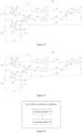
- Figure 16 is a block diagram showing a device for controlling an air conditioner according to an embodiment of the present disclosure.
- the air conditioner includes an outdoor heat exchanger, an indoor heat exchanger, a heat storage heat exchanger, a compressor, a four-way valve assembly, and a throttling assembly.
- the outdoor heat exchanger and the indoor heat exchanger are connected to a bypass through a first pipeline.
- the outdoor heat exchanger is connected to the compressor through a second pipeline.
- the indoor heat exchanger is connected to the compressor through a third pipeline.
- the heat storage heat exchanger is arranged at the bypass, and the throttling assembly is arranged at the bypass.
- the four-way valve assembly includes a first four-way valve and a second four-way valve. The first four-way valve is arranged at the second pipeline, and the second four-way valve is arranged at the third pipeline.
- the device 200 for controlling the air conditioner includes: an identifying module 21 and a responding module 22.
- the identifying module is configured to identify an operation mode of the air conditioner.
- the responding module 22 is configured to control the first four-way valve and the second four-way valve both to be powered on in response to the operation mode of the air conditioner being a heating mode.
- the responding module 22 is also configured to control the first four-way valve to be powered off and the second four-way valve to be powered on in response to the operation mode of the air conditioner being a defrosting mode.
- the device 200 for controlling the air conditioner further includes a controlling module.
- the identifying module is configured to control the first four-way valve and the second four-way valve both to be powered on, in response to identifying that the outdoor heat exchanger is of a pipe-wall temperature higher than or equal to a first preset temperature and/or that a defrosting duration reaches a first preset duration.
- the device 200 for controlling the air conditioner further includes a determining module, configured to determine whether the air conditioner is in a target operation state, wherein the target operation state includes a heating target operation state and a cooling target operation state; and the responding module is further configured to control the throttling assembly to switch on in response to the air conditioner being in the target operation state, or control the throttling assembly to switch off in response to the air conditioner being out of the target operation state.
- a determining module configured to determine whether the air conditioner is in a target operation state, wherein the target operation state includes a heating target operation state and a cooling target operation state
- the responding module is further configured to control the throttling assembly to switch on in response to the air conditioner being in the target operation state, or control the throttling assembly to switch off in response to the air conditioner being out of the target operation state.
- the determining module is specifically configured to determine that the air conditioner is in the target operation state, in response to identifying that the air conditioner is of a heating capacity demand parameter or a cooling capacity demand parameter lower than or equal to a first preset threshold for a second preset duration; or determine that the air conditioner is out of the target operation state, in response to identifying that the air conditioner is of a heating capacity demand parameter or a cooling capacity demand parameter greater than or equal to a second preset threshold for a third preset duration.
- the air conditioner includes a plurality of the indoor heat exchangers
- the determining module is specifically configured to, based on that the operation mode of the air conditioner is a mixed mode, wherein the mixed mode includes the heating mode for at least one of the indoor heat exchangers and a cooling mode for at least one of the indoor heat exchangers, acquire a heating capacity demand parameter and a cooling capacity demand parameter; determine that the air conditioner is in the heating target operation state, in response to identifying that the heating capacity demand parameter is lower than or equal to the cooling capacity demand parameter, or determine that the air conditioner is in the cooling target operation state, in response to identifying that the heating capacity demand parameter is greater than the cooling capacity demand parameter.
- the responding module is further configured to identify that the indoor heat exchanger is of a pipe-wall temperature higher than or equal to a second preset temperature for a fourth preset duration in response to the air conditioner being in the heating target operation state; or identify that the indoor heat exchanger is of a pipe-wall temperature lower than or equal to a third preset temperature for a fifth preset duration in response to the air conditioner being in the cooling target operation state.
- the responding module is further configured to, based on that the air conditioner is in the heating target operation state, control the first four-way valve to be powered off, in response to identifying that the heat storage heat exchanger is of an outlet pipe-wall temperature greater than or equal to a fourth preset temperature for a sixth preset duration; and control the first four-way valve to be powered on, and return back to determine whether the air conditioner is in the target operation state and subsequent steps thereof, in response to identifying that the heat storage heat exchanger is of an inlet pipe-wall temperature lower than or equal to a fifth preset temperature and/or that the first four-way valve has been powered off for a seventh preset duration.
- the responding module is further configured to, based on that the air conditioner is in the cooling target operation state, control the first four-way valve to be powered on, in response to identifying that the heat storage heat exchanger is of an outlet pipe-wall temperature lower than or equal to a sixth preset temperature for an eighth preset duration; and control the first four-way valve to be powered off, and return back to determine whether the air conditioner is in the target operation state and subsequent steps thereof, in response to identifying that the heat storage heat exchanger is of an inlet pipe-wall temperature greater than or equal to a seventh preset temperature and/or that the first four-way valve has been powered on for a ninth preset duration.
- the four-way valve assembly further includes a third four-way valve arranged at the bypass; and the responding module is further configured to control the third four-way valve to be powered off in response to the operation mode of the air conditioner being the heating mode; and control the third four-way valve to be powered on in response to the operation mode of the air conditioner being the defrosting mode.
- the responding module is further configured to control the first four-way valve and the second four-way valve both to be powered off and the third four-way valve to be powered on, in response to the operation mode of the air conditioner being the cooling mode.
- the device for controlling the air conditioner identifies the operation mode of the air conditioner; controls the first four-way valve and the second four-way valve both to be powered on in response to the operation mode of the air conditioner being the heating mode; and controls the first four-way valve to be powered off and the second four-way valve to be powered on in response to the operation mode of the air conditioner being the defrosting mode.
- the outdoor heat exchanger and the indoor heat exchanger each serve as the condenser, while the heat storage heat exchanger serves as the evaporator, such that heat is absorbed from the heat storage heat exchanger for defrosting the outdoor heat exchanger without adversely affecting the heating performance of the indoor heat exchanger, thereby improving the air conditioner for comfort and user's experience.
- the present disclosure further provides in an embodiment an air conditioner 1000.
- the air conditioner 1000 includes: the outdoor heat exchanger 11, the indoor heat exchanger 12, the heat storage heat exchanger 13, the compressor 14, the four-way valve assembly 15, and the throttling assembly 16.
- the outdoor heat exchanger 11 and the indoor heat exchanger are connected to a bypass through a first pipeline.
- the outdoor heat exchanger 11 is connected to the compressor 14 through the second pipeline 173.
- the indoor heat exchanger 12 is connected to the compressor 14 through the third pipeline 174.
- the heat storage heat exchanger 13 is arranged at the bypass 172, and the bypass 172 is provided with the throttling assembly 16.
- the four-way valve assembly 15 includes the first four-way valve 151 and the second four-way valve 152.
- the first four-way valve 151 is arranged at the second pipeline 173, and the second four-way valve 152 is arranged at the third pipeline 174.
- the air conditioner 1000 also includes the device 200 for controlling the air conditioner as described above. It should note that the air conditioner as illustrated in Figure 17 is merely an example of the air conditioner in an embodiment of the present disclosure, rather than limitation to the air conditioner in an embodiment of the present disclosure.
- the four-way valve assembly further includes a third four-way valve arranged at the bypass.
- the air conditioner identifies the operation mode of the air conditioner; controls the first four-way valve and the second four-way valve both to be powered on in response to the operation mode of the air conditioner being the heating mode; and controls the first four-way valve to be powered off and the second four-way valve to be powered on in response to the operation mode of the air conditioner being the defrosting mode.
- the outdoor heat exchanger and the indoor heat exchanger each serve as the condenser, while the heat storage heat exchanger serves as the evaporator, such that heat is absorbed from the heat storage heat exchanger for defrosting the outdoor heat exchanger without adversely affecting the heating performance of the indoor heat exchanger, thereby improving the air conditioner for comfort and user's experience.
- the present disclosure further provides in an embodiment an electronic device 300.
- the electronic device includes a memory 31 and a processor 32.
- the processor 32 runs a program corresponding to an executable program code by reading the executable program code stored in the memory 32, to implement the method for controlling the air conditioner as described above.
- the electronic device by means of the processor executing the computer program stored in the memory, identifies the operation mode of the air conditioner; controls the first four-way valve and the second four-way valve both to be powered on in response to the operation mode of the air conditioner being the heating mode; and controls the first four-way valve to be powered off and the second four-way valve to be powered on in response to the operation mode of the air conditioner being the defrosting mode.
- the outdoor heat exchanger and the indoor heat exchanger each serve as a condenser, while the heat storage heat exchanger serves as an evaporator, such that heat is absorbed from the heat storage heat exchanger for defrosting the outdoor heat exchanger without adversely affecting the heating performance of the indoor heat exchanger, thereby improving the air conditioner for comfort and user's experience.
- the present disclosure further provides in an embodiment a computer readable storage medium having stored therein a computer program that, when executed by a processor, implements the method for controlling the air conditioner as described above.
- the computer readable storage medium by having stored therein the computer program that is executed by the processor, identifies the operation mode of the air conditioner; controls the first four-way valve and the second four-way valve both to be powered on in response to the operation mode of the air conditioner being the heating mode; and controls the first four-way valve to be powered off and the second four-way valve to be powered on in response to the operation mode of the air conditioner being the defrosting mode.
- the outdoor heat exchanger and the indoor heat exchanger each serve as a condenser, while the heat storage heat exchanger serves as an evaporator, such that heat is absorbed from the heat storage heat exchanger for defrosting the outdoor heat exchanger without adversely affecting the heating performance of the indoor heat exchanger, thereby improving the air conditioner for comfort and user's experience.
- orientation or position relationship such as “central”, “longitudinal”, “lateral”, “width”, “thickness”, “above”, “below”, “front”, “rear”, “right”, “left”, “vertical”, “horizontal”, “top”, “bottom”, “inner”, “outer”, “clockwise”, “counter-clockwise”, “axial”, “radial”, “circumferential” should be construed to refer to the orientation or position relationship as described or as shown in the drawings. These terms are merely for convenience and concision of description and do not alone indicate or imply that the device or element referred to must have a particular orientation or must be configured or operated in a particular orientation. Thus, it cannot be understood to limit the present disclosure.
- first and second are used herein for purposes of description and are not intended to indicate or imply relative importance or significance or impliedly indicate quantity of the technical feature referred to.
- the feature defined with “first” and “second” may includes one or more this features.
- a plurality of means two or more than two this features, unless specified otherwise.
- the terms “mounted”, “connected”, “coupled”, “fixed” and the like are used broadly, and may be, for example, a fixed connection, a detachable connection, or an integrated connection; may also be a mechanical or electrical connection; may also be a direct connections or indirect connection via an intervening structure; may also be an inner communication of two elements or a mutual interaction between two elements, which can be understood by those skilled in the art according to specific situations.
- a structure in which a first feature is "on" or “below” a second feature may be an embodiment in which the first feature is in direct contact with the second feature, or an embodiment in which the first feature and the second feature are contacted indirectly via an intermediation.
- a first feature "on”, “above” or “on top of' a second feature may be an embodiment in which the first feature is right or obliquely “on”, “above” or “on top of' the second feature, or merely means that the first feature is at a height higher than that of the second feature; while a first feature “below”, “under” or “on bottom of” a second feature may be an embodiment in which the first feature is right or obliquely “below”, “under” or “on bottom of' the second feature, or merely means that the first feature is at a height lower than that of the second feature.
Landscapes
- Engineering & Computer Science (AREA)
- Mechanical Engineering (AREA)
- General Engineering & Computer Science (AREA)
- Physics & Mathematics (AREA)
- Signal Processing (AREA)
- Chemical & Material Sciences (AREA)
- Combustion & Propulsion (AREA)
- Thermal Sciences (AREA)
- Fuzzy Systems (AREA)
- Mathematical Physics (AREA)
- Fluid Mechanics (AREA)
- Air Conditioning Control Device (AREA)
Abstract
Description
- This application claims priority to and benefits of the
Chinese Patent Application No. "202110277853.X" submitted by GD MIDEA HEATING & VENTILATING EQUIPMENT CO., LTD. and HEFEI MIDEA HEATING & VENTILATING EQUIPMENT CO., LTD. with the title of "METHOD AND DEVICE FOR CONTROLLING AIR CONDITIONER" filed on March 15, 2021 - The present disclosure relates to the field of an air conditioner technology, particularly relates to a method and device for controlling an air conditioner, an air conditioner, an electronic device and a computer readable storage medium.
- At present, with the improvement of people's living standard, an air conditioner has also been on an increasing comfort requirement. In the related art, it is prone for an outdoor unit to frost in a heating mode serving as an evaporator; while during a defrosting process, an indoor unit is converted to serve as the evaporator and the outdoor unit is converted to serve as a condenser to absorb heat from indoor for defrosting the outdoor unit, resulting in poor heating performance of the indoor unit, thus adversely affecting the user's experience.
- The present disclosure aims to solve at least one of the technical problems in the related art to a certain degree.
- For this, an object of the present disclosure is to propose a method for controlling an air conditioner, which identifies an operation mode of the air conditioner; controls the first four-way valve and the second four-way valve both to be powered on in response to the operation mode of the air conditioner being a heating mode; and controls the first four-way valve to be powered off and the second four-way valve to be powered on in response to the operation mode of the air conditioner being a defrosting mode. Accordingly, when the operation mode of the air conditioner is the defrosting mode, the outdoor heat exchanger and the indoor heat exchanger each serve as a condenser, while the heat storage heat exchanger serves as an evaporator, such that heat is absorbed from the heat storage heat exchanger for defrosting the outdoor heat exchanger without adversely affecting the heating performance of the indoor heat exchanger, thereby improving the air conditioner for comfort and user's experience.
- A second object of the present disclosure is to propose a device for controlling an air conditioner.
- A third object of the present disclosure is to provide an air conditioner.
- A fourth object of the present disclosure is to provide an electronic device.
- A fifth object of the present disclosure is to provide a computer readable storage medium.
- To achieve the above objects, in a first aspect, the present disclosure provides in an embodiment a method for controlling an air conditioner, wherein the air conditioner includes an outdoor heat exchanger, an indoor heat exchanger, a heat storage heat exchanger, a compressor, a four-way valve assembly, and a throttling assembly, the outdoor heat exchanger and the indoor heat exchanger are connected to a bypass through a first pipeline, the outdoor heat exchanger is connected to the compressor through a second pipeline, the indoor heat exchanger is connected to the compressor through a third pipeline, wherein the heat storage heat exchanger is arranged at the bypass, the throttling assembly is arranged at the bypass, the four-way valve assembly includes a first four-way valve and a second four-way valve, the first four-way valve is arranged at the second pipeline, the second four-way valve is arranged at the third pipeline,
the method for controlling the air conditioner includes: identifying an operation mode of the air conditioner; controlling the first four-way valve and the second four-way valve both to be powered on in response to the operation mode of the air conditioner being a heating mode; and controlling the first four-way valve to be powered off and the second four-way valve to be powered on in response to the operation mode of the air conditioner being a defrosting mode. - According to an embodiment of the present disclosure, the method for controlling the air conditioner identifies the operation mode of the air conditioner; controls the first four-way valve and the second four-way valve both to be powered on in response to the operation mode of the air conditioner being the heating mode; and controls the first four-way valve to be powered off and the second four-way valve to be powered on in response to the operation mode of the air conditioner being the defrosting mode. Accordingly, when the operation mode of the air conditioner is the defrosting mode, the outdoor heat exchanger and the indoor heat exchanger each serve as a condenser, while the heat storage heat exchanger serves as an evaporator, such that heat is absorbed from the heat storage heat exchanger for defrosting the outdoor heat exchanger without adversely affecting the heating performance of the indoor heat exchanger, thereby improving the air conditioner for comfort and user's experience.
- In addition, the method for controlling the air conditioner proposed according to the above embodiment of the present disclosure may further include the following additional technical features.
- In an embodiment of the present disclosure, after controlling the first four-way valve to be powered off and the second four-way valve to be powered on, the method further includes: controlling the first four-way valve and the second four-way valve both to be powered on, in response to identifying that a pipe-wall temperature of the outdoor heat exchanger is higher than or equal to a first preset temperature and/or that a defrosting duration reaches a first preset duration.
- In an embodiment of the present disclosure, the method further includes: determining whether the air conditioner is in a target operation state, wherein the target operation state includes a heating target operation state and a cooling target operation state; and controlling the throttling assembly to switch on in response to the air conditioner being in the target operation state, or controlling the throttling assembly to switch off in response to the air conditioner being not in the target operation state.
- In an embodiment of the present disclosure, determining whether the air conditioner is in the target operation state includes: determining that the air conditioner is in the target operation state, in response to identifying that the air conditioner is of a heating capacity demand parameter or a cooling capacity demand parameter lower than or equal to a first preset threshold for a second preset duration; or determining that the air conditioner is out of the target operation state, in response to identifying that the air conditioner is of a heating capacity demand parameter or a cooling capacity demand parameter greater than or equal to a second preset threshold for a third preset duration.
- In an embodiment of the present disclosure, the air conditioner includes a plurality of the indoor heat exchangers, and determining whether the air conditioner is in the target operation state further includes: based on that the operation mode of the air conditioner is a mixed mode, wherein the mixed mode includes the heating mode for at least one of the indoor heat exchangers and a cooling mode for at least one of the indoor heat exchangers, acquiring a heating capacity demand parameter and a cooling capacity demand parameter; determining that the air conditioner is in the heating target operation state, in response to identifying that the heating capacity demand parameter is lower than or equal to the cooling capacity demand parameter, or determining that the air conditioner is in the cooling target operation state, in response to identifying that the heating capacity demand parameter is greater than the cooling capacity demand parameter.
- In an embodiment of the present disclosure, prior to controlling the throttling assembly to switch on, the method further includes: identifying that a duration during which a pipe-wall temperature of the indoor heat exchanger is higher than or equal to a second preset temperature reaches a fourth preset duration in response to the air conditioner being in the heating target operation state; or identifying that a duration during which a pipe-wall temperature of the indoor heat exchanger is lower than or equal to a third preset temperature reaches a fifth preset duration in response to the air conditioner being in the cooling target operation state.
- In an embodiment of the present disclosure, after controlling the throttling assembly to switch on, the method further includes: based on that the air conditioner is in the heating target operation state, controlling the first four-way valve to be powered off, in response to identifying that a duration during which an outlet pipe-wall temperature of the heat storage heat exchanger is greater than or equal to a fourth preset temperature reaches a sixth preset duration; and controlling the first four-way valve to be powered on, and returning to perform the step of determining whether the air conditioner is in the target operation state and subsequent steps thereof, in response to identifying that a duration during which an inlet pipe-wall temperature of the heat storage heat exchanger is lower than or equal to a fifth preset temperature and/or that a duration during which the first four-way valve is powered off reaches a seventh preset duration.
- In an embodiment of the present disclosure, after controlling the throttling assembly to switch on, the method further includes: based on that the air conditioner is in the cooling target operation state, controlling the first four-way valve to be powered on, in response to identifying that a duration during which an outlet pipe-wall temperature of the heat storage heat exchanger is lower than or equal to a sixth preset temperature reaches an eighth preset duration; and controlling the first four-way valve to be powered off, and returning to the step of determining whether the air conditioner is in the target operation state and subsequent steps thereof, in response to identifying that a duration during which an inlet pipe-wall temperature of the heat storage heat exchanger is greater than or equal to a seventh preset temperature and/or that a duration during which the first four-way valve is powered on reaches a ninth preset duration.
- In an embodiment of the present disclosure, the four-way valve assembly further includes a third four-way valve arranged at the bypass; the method further includes: controlling the third four-way valve to be powered off in response to the operation mode of the air conditioner being the heating mode; and controlling the third four-way valve to be powered on in response to the operation mode of the air conditioner being the defrosting mode.
- In an embodiment of the present disclosure, the method further includes: controlling the first four-way valve and the second four-way valve both to be powered off and the third four-way valve to be powered on, in response to the operation mode of the air conditioner being the cooling mode.
- To achieve the above objects, in a second aspect, the present disclosure provides in an embodiment a device for controlling an air conditioner, the air conditioner includes an outdoor heat exchanger, an indoor heat exchanger, a heat storage heat exchanger, a compressor, a four-way valve assembly, and a throttling assembly, the outdoor heat exchanger and the indoor heat exchanger are connected to a bypass through a first pipeline, the outdoor heat exchanger is connected to the compressor through a second pipeline, the indoor heat exchanger is connected to the compressor through a third pipeline, wherein the heat storage heat exchanger is arranged at the bypass, the throttling assembly is arranged at the bypass, the four-way valve assembly includes a first four-way valve and a second four-way valve, the first four-way valve is arranged at the second pipeline, the second four-way valve is arranged at the third pipeline,
the device for controlling the air conditioner includes: an identifying module, configured to identify an operation mode of the air conditioner; and a responding module, configured to control the first four-way valve and the second four-way valve both to be powered on in response to the operation mode of the air conditioner being a heating mode; and control the first four-way valve to be powered off and the second four-way valve to be powered on in response to the operation mode of the air conditioner being a defrosting mode. - According to an embodiment of the present disclosure, the device for controlling the air conditioner identifies the operation mode of the air conditioner; controls the first four-way valve and the second four-way valve both to be powered on in response to the operation mode of the air conditioner being the heating mode; and controls the first four-way valve to be powered off and the second four-way valve to be powered on in response to the operation mode of the air conditioner being the defrosting mode. Accordingly, when the operation mode of the air conditioner is the defrosting mode, the outdoor heat exchanger and the indoor heat exchanger each serve as a condenser, while the heat storage heat exchanger serves as an evaporator, such that heat is absorbed from the heat storage heat exchanger for defrosting the outdoor heat exchanger without adversely affecting the heating performance of the indoor heat exchanger, thereby improving the air conditioner for comfort and user's experience.
- In addition, the device for controlling the air conditioner proposed according to the above embodiment of the present disclosure may further include the following additional technical features.
- In an embodiment of the present disclosure, the device for controlling the air conditioner further includes a control module, wherein after the first four-way valve is controlled to be powered off and the second four-way valve is controlled to be powered on, an identifying module is configured to control the first four-way valve and the second four-way valve both to be powered on, in response to identifying that a pipe-wall temperature of the outdoor heat exchanger is higher than or equal to a first preset temperature and/or that a defrosting duration reaches a first preset duration.
- In an embodiment of the present disclosure, the device for controlling the air conditioner further includes an identifying module, configured to determine whether the air conditioner is in a target operation state, wherein the target operation state includes a heating target operation state and a cooling target operation state; and the responding module is further configured to control the throttling assembly to switch on in response to the air conditioner being in the target operation state, or control the throttling assembly to switch off in response to the air conditioner being not in the target operation state.
- In an embodiment of the present disclosure, the determining module is specifically configured to determine that the air conditioner is in the target operation state, in response to identifying that a duration during which a heating capacity demand parameter or a cooling capacity demand parameter of the air conditioner is lower than or equal to a first preset threshold reaches a first preset threshold for a second preset duration; or determine that the air conditioner is not in the target operation state, in response to identifying that a duration during which a heating capacity demand parameter or a cooling capacity demand parameter of the air conditioner is greater than or equal to a second preset threshold reaches a third preset duration.
- In an embodiment of the present disclosure, the air conditioner includes a plurality of the indoor heat exchangers, and the determining module is specifically configured to, based on that the operation mode of the air conditioner is a mixed mode, wherein the mixed mode includes the heating mode for at least one of the indoor heat exchangers and a cooling mode for at least one of the indoor heat exchangers, acquire a heating capacity demand parameter and a cooling capacity demand parameter; determine that the air conditioner is in the heating target operation state, in response to identifying that the heating capacity demand parameter is lower than or equal to the cooling capacity demand parameter, or determine that the air conditioner is in the cooling target operation state, in response to identifying that the heating capacity demand parameter is greater than the cooling capacity demand parameter.
- In an embodiment of the present disclosure, before the throttling assembly is controlled to switch on, the responding module is further configured to identify that a duration during which a pipe-wall temperature of the indoor heat exchanger is higher than or equal to a second preset temperature reaches a fourth preset duration in response to the air conditioner being in the heating target operation state; or identify that a duration during which a pipe-wall temperature of the indoor heat exchanger is lower than or equal to a third preset temperature reaches a fifth preset duration in response to the air conditioner being in the cooling target operation state.
- In an embodiment of the present disclosure, after the throttling assembly is controlled to switch on, the responding module is further configured to, based on that the air conditioner is in the heating target operation state, control the first four-way valve to be powered off, in response to identifying that a duration during which an outlet pipe-wall temperature of the heat storage heat exchanger is greater than or equal to a fourth preset temperature reaches a sixth preset duration; and control the first four-way valve to be powered on, and returning to perform the step of determining whether the air conditioner) is in the target operation state and subsequent steps thereof, in response to identifying that a duration during which an inlet pipe-wall temperature of the heat storage heat exchanger is lower than or equal to a fifth preset temperature and/or that a duration during which the first four-way valve is powered off reaches a seventh preset duration.
- In an embodiment of the present disclosure, after the throttling assembly is controlled to switch on, the responding module is further configured to, based on that the air conditioner is in the cooling target operation state, control the first four-way valve to be powered on, in response to identifying that a duration during which an outlet pipe-wall temperature of the heat storage heat exchanger is lower than or equal to a sixth preset temperature reaches an eighth preset duration; and control the first four-way valve to be powered off, and returning to the step of determining whether the air conditioner is in the target operation state and subsequent steps thereof, in response to identifying that a duration during which an inlet pipe-wall temperature of the heat storage heat exchanger is greater than or equal to a seventh preset temperature and/or that a duration during which the first four-way valve is powered on reaches a ninth preset duration.
- In an embodiment of the present disclosure, the four-way valve assembly further includes a third four-way valve arranged at the bypass; and the responding module is further configured to control the third four-way valve to be powered off in response to the operation mode of the air conditioner being the heating mode; and control the third four-way valve to be powered on in response to the operation mode of the air conditioner being the defrosting mode.
- In an embodiment of the present disclosure, the responding module is further configured to control the first four-way valve and the second four-way valve both to be powered off and the third four-way valve to be powered on, in response to the operation mode of the air conditioner being the cooling mode.
- To achieve the above objects, in a third aspect, the present disclosure provides in an embodiment an air conditioner, including: an outdoor heat exchanger, an indoor heat exchanger, a heat storage heat exchanger, a compressor, a four-way valve assembly, and a throttling assembly, wherein the outdoor heat exchanger and the indoor heat exchanger are connected to a bypass through a first pipeline, the outdoor heat exchanger is connected to the compressor through a second pipeline, the indoor heat exchanger is connected to the compressor through a third pipeline, wherein the heat storage heat exchanger is arranged at the bypass, the throttling assembly is arranged at the bypass, the four-way valve assembly includes a first four-way valve and a second four-way valve, the first four-way valve is arranged at the second pipeline, the second four-way valve is arranged at the third pipeline; and a device for controlling an air conditioner as described in embodiments in the second aspect of the present disclosure.
- According to an embodiment of the present disclosure, the air conditioner identifies the operation mode of the air conditioner; controls the first four-way valve and the second four-way valve both to be powered on in response to the operation mode of the air conditioner being the heating mode; and controls the first four-way valve to be powered off and the second four-way valve to be powered on in response to the operation mode of the air conditioner being the defrosting mode. Accordingly, when the operation mode of the air conditioner is the defrosting mode, the outdoor heat exchanger and the indoor heat exchanger each serve as a condenser, while the heat storage heat exchanger serves as an evaporator, such that heat is absorbed from the heat storage heat exchanger for defrosting the outdoor heat exchanger without adversely affecting the heating performance of the indoor heat exchanger, thereby improving the air conditioner for comfort and user's experience.
- In addition, the air conditioner proposed according to the above embodiment of the present disclosure may further include the following additional technical feature.
- In an embodiment of the present disclosure, the four-way valve assembly further includes a third four-way valve arranged at the bypass.
- To achieve the above objects, in a fourth aspect, the present disclosure provides in an embodiment an electronic device, including a memory and a processor, wherein the processor runs a program corresponding to an executable program code by reading the executable program code stored in the memory, to implement a method for controlling an air conditioner as described in embodiments of the first aspect of the present disclosure.
- According to an embodiment of the present disclosure, the electronic device, by means of the processor executing the computer program stored in the memory, identifies the operation mode of the air conditioner; controls the first four-way valve and the second four-way valve both to be powered on in response to the operation mode of the air conditioner being the heating mode; and controls the first four-way valve to be powered off and the second four-way valve to be powered on in response to the operation mode of the air conditioner being the defrosting mode. Accordingly, when the operation mode of the air conditioner is the defrosting mode, the outdoor heat exchanger and the indoor heat exchanger each serve as a condenser, while the heat storage heat exchanger serves as an evaporator, such that heat is absorbed from the heat storage heat exchanger for defrosting the outdoor heat exchanger without adversely affecting the heating performance of the indoor heat exchanger, thereby improving the air conditioner for comfort and user's experience.
- To achieve the above objects, in a fifth aspect, the present disclosure provides in an embodiment a computer readable storage medium having stored therein a computer program that, when executed by a processor, implements a method for controlling an air conditioner as described in embodiments of the first aspect of the present disclosure.
- According to an embodiment of the present disclosure, the computer readable storage medium, by having stored therein the computer program that is executed by the processor, identifies the operation mode of the air conditioner; controls the first four-way valve and the second four-way valve both to be powered on in response to the operation mode of the air conditioner being the heating mode; and controls the first four-way valve to be powered off and the second four-way valve to be powered on in response to the operation mode of the air conditioner being the defrosting mode. Accordingly, when the operation mode of the air conditioner is the defrosting mode, the outdoor heat exchanger and the indoor heat exchanger each serve as a condenser, while the heat storage heat exchanger serves as an evaporator, such that heat is absorbed from the heat storage heat exchanger for defrosting the outdoor heat exchanger without adversely affecting the heating performance of the indoor heat exchanger, thereby improving the air conditioner for comfort and user's experience.
- The additional aspects and advantages of the present disclosure will be partially provided in the following description, which will become apparent from the following description or learned through the practice of the present disclosure.
- The above and/or additional aspects and advantages of the present disclosure will become obvious and understandable with the following description for embodiments in combination with the drawings, in which:
-
Figure 1 is a flow chart showing a method for controlling an air conditioner according to an embodiment of the present disclosure; -
Figure 2 is a schematic diagram showing a structure of an air conditioner according to an embodiment of the present disclosure; -
Figure 3 is a schematic diagram showing a refrigerant flow direction in an air conditioner according to an embodiment of the present disclosure; -
Figure 4 is a schematic diagram showing a refrigerant flow direction in an air conditioner according to another embodiment of the present disclosure; -
Figure 5 is a flow chart showing a method for controlling an air conditioner after identifying an operation mode of the air conditioner according to an embodiment of the present disclosure; -
Figure 6 is a schematic diagram showing a structure of an air conditioner according to another embodiment of the present disclosure; -
Figure 7 is a flow chart showing a method for controlling an air conditioner according to another embodiment of the present disclosure; -
Figure 8 is a flow chart showing a method for controlling an air conditioner according to another embodiment of the present disclosure; -
Figure 9 is a schematic diagram showing a refrigerant flow direction in an air conditioner according to another embodiment of the present disclosure; -
Figure 10 is a schematic diagram showing a refrigerant flow direction in an air conditioner according to another embodiment of the present disclosure; -
Figure 11 is a flow chart showing a method for controlling an air conditioner according to another embodiment of the present disclosure; -
Figure 12 is a schematic diagram showing a structure of an air conditioner according to another embodiment of the present disclosure; -
Figure 13 is a schematic diagram showing a refrigerant flow direction in an air conditioner according to another embodiment of the present disclosure; -
Figure 14 is a schematic diagram showing a refrigerant flow direction in an air conditioner according to another embodiment of the present disclosure; -
Figure 15 is a schematic diagram showing a refrigerant flow direction in an air conditioner according to another embodiment of the present disclosure; -
Figure 16 is a block diagram showing a device for controlling an air conditioner according to an embodiment of the present disclosure; -
Figure 17 is a block diagram showing an air conditioner according to an embodiment of the present disclosure; and -
Figure 18 is a block diagram showing an electronic device according to an embodiment of the present disclosure. - Reference will be made in details to embodiments of the present disclosure. The same or similar elements and the elements having same or similar functions are denoted by like reference numerals throughout the descriptions. The embodiments described herein with reference to drawings are explanatory, illustrative, and used to generally understand the present disclosure. The embodiments shall not be construed to limit the present disclosure.
- A method and device for controlling an air conditioner, an air conditioner, an electronic device and a computer readable storage medium in embodiments of the present disclosure are described below in combination with the drawings.
-
Figure 1 is a flow chart showing a method for controlling an air conditioner according to an embodiment of the present disclosure. - It should note that, as shown in
Figure 2 , in an embodiment of the present disclosure, the air conditioner includes theoutdoor heat exchanger 11, theindoor heat exchanger 12, the heatstorage heat exchanger 13, thecompressor 14, the four-way valve assembly 15, and the throttlingassembly 16. It should note that the air conditioner illustrated inFigure 2 is merely an example of the air conditioner in an embodiment of the present disclosure, rather than limitation to the air conditioner in an embodiment of the present disclosure. - The
outdoor heat exchanger 11 and theindoor heat exchanger 12 are connected to abypass 172 through afirst pipeline 171; theoutdoor heat exchanger 11 is connected to thecompressor 14 through thesecond pipeline 173; and theindoor heat exchanger 12 is connected to thecompressor 14 through thethird pipeline 174. The heatstorage heat exchanger 13 is arranged at thebypass 172, and thebypass 172 is provided with the throttlingassembly 16. The four-way valve assembly 15 includes the first four-way valve 151 and the second four-way valve 152. The first four-way valve 151 is arranged at thesecond pipeline 173; and the second four-way valve 152 is arranged at thethird pipeline 174. Optionally, thefirst pipeline 171 is provided with the throttlingassembly 16. - Optionally, the first four-
way valve 151 and the second four-way valve 152 each may be an electronic expansion valve. - As shown in
Figure 1 , in an embodiment of the present disclosure, the method for controlling the air conditioner includes the following steps. - At S101, an operation mode of the air conditioner is identified.
- It would be appreciated that the operation mode of the air conditioner may be set according to an actual situation. For example, a user may set the operation mode of the air conditioner in a flexible way. Optionally, the use may set the operation mode of the air conditioner by a remote controller, an Application (APP) for the air conditioner in a mobile terminal, or a control panel on a body of the air conditioner, or through a non-contact approach such as a language and a gesture.
- Further, one may acquire a setting parameter with respect to the operation mode from the remote controller, the Application (APP) for the air conditioner in the mobile terminal, or the control panel on the body of the air conditioner, to identify the operating mode of the air conditioner.
- At S102, in response to the operation mode of the air conditioner being a heating mode, the first four-way valve and the second four-way valve both are controlled to be powered on.
- In an embodiment of the present disclosure, in response to the operation mode of the air conditioner being the heating mode, the first four-
way valve 151 and the second four-way valve 152 both are controlled to be powered on. - As shown in
Figure 3 , the first four-way valve 151 is controlled to be powered on, enabling the pipeline between the interface A and the interface B of the first four-way valve 151 to be connected and the pipeline between the interface C and the interface D of the first four-way valve 151 to be connected, while the pipeline between the interface A and the interface D of the first four-way valve 151 to be disconnected and the pipeline between the interface B and the interface C of the first four-way valve 151 to be disconnected. - The second four-
way valve 152 is controlled to be powered on, enabling the pipeline between the interface A and the interface D of the second four-way valve 152 to be connected and the pipeline between the interface B and the interface C of the second four-way valve 152 to be connected, while the pipeline between the interface A and the interface B of the second four-way valve 152 to be disconnected and the pipeline between the interface C and the interface D of the second four-way valve 152 to be disconnected. -
Figure 3 shows a refrigerant flow direction in the air conditioner with the above-described connections, where a portion of a high-temperature and high-pressure refrigerant discharged from thecompressor 14 enters theindoor heat exchanger 12 for heat release and condensation through thethird pipeline 174, and the pipeline between the interface B and the interface C of the second four-way valve 152; another portion of the high-temperature and high-pressure refrigerant discharged from thecompressor 14 enters the heatstorage heat exchanger 13 for heat release and condensation through the pipeline between the interface C and the interface D of the first four-way valve 151 and thebypass 172, followed by throttling and depressurizing through the throttlingassembly 16; and the refrigerant enters theoutdoor heat exchanger 11 for heat absorption and evaporation, and returns back to thecompressor 14 through the pipeline between the interface A and the interface B of the first four-way valve 151 and thesecond pipeline 173. - It would be appreciated that, in an embodiment of the present disclosure, when the operation mode of the air conditioner is the heating mode, the
outdoor heat exchanger 11 serves as an evaporator, while theindoor heat exchanger 12 and the heatstorage heat exchanger 13 each serve as a condenser. In other words, when the operation mode of the air conditioner is the heating mode, the heatstorage heat exchanger 13 is used to store heat. - At S 103, in response to the operation mode of the air conditioner being a defrosting mode, the first four-way valve is controlled to be powered off, and the second four-way valve is controlled to be powered on.
- In an embodiment of the present disclosure, in response to the operation mode of the air conditioner being the defrosting mode, the first four-
way valve 151 is controlled to be powered off, and the second four-way valve 152 is controlled to be powered on. - As shown in
Figure 4 , the first four-way valve 151 is controlled to be powered off, enabling the pipeline between the interface A and the interface D of the first four-way valve 151 to be connected and the pipeline between the interface B and the interface C of the first four-way valve 151 to be connected, while the pipeline between the interface A and the interface B of the first four-way valve 151 to be disconnected and the pipeline between the interface C and the interface D of the first four-way valve 151 to be disconnected. - With respect to the relevant description on controlling the second four-
way valve 152 to be powered on, please refer to the above embodiments, which will not be repeated here. -
Figure 4 shows a refrigerant flow direction in the air conditioner with the above-described connections, where a portion of a high-temperature and high-pressure refrigerant discharged from thecompressor 14 enters theindoor heat exchanger 12 for heat release and condensation through thethird pipeline 174, and the pipeline between the interface B and the interface C of the second four-way valve 152; another portion of the high-temperature and high-pressure refrigerant discharged from thecompressor 14 enters theoutdoor heat exchanger 11 for heat release and condensation through the pipeline between the interface B and the interface C of the first four-way valve 151, and thesecond pipeline 173; the refrigerant is throttled and depressurized through the throttlingassembly 16, before enters the heatstorage heat exchanger 13 for heat absorption and evaporation, and returns back to thecompressor 14 through thebypass 172, the pipeline between the interface A and the interface D of the first four-way valve 151 and thesecond pipeline 173. - It would be appreciated that, in an embodiment of the present disclosure, when the operation mode of the air conditioner is the defrosting mode, the
outdoor heat exchanger 11 and theindoor exchanger 12 each serve as a condenser, and the heatstorage heat exchanger 13 serves as an evaporator. In other words, when the operation mode of the air conditioner is changed from the heating mode to the defrosting mode, theoutdoor heat exchanger 11 is converted from serving as the evaporator to serving as the condenser, theindoor heat exchanger 12 continues serving as the condenser, and the heatstorage heat exchanger 13 is converted from serving as the condenser to serving the evaporator, such that the heat is absorbed from the heatstorage heat exchanger 13 for defrosting theoutdoor heat exchanger 11 without adversely affecting the heating performance of theindoor heat exchanger 12, thereby improving the air conditioner for comfort and user's experience. - Summing up the above, according to embodiments of the present disclosure, the method for controlling the air conditioner identifies the operation mode of the air conditioner; controls the first four-way valve and the second four-way valve both to be powered on in response to the operation mode of the air conditioner being the heating mode; and controls the first four-way valve to be powered off and the second four-way valve to be powered on in response to the operation mode of the air conditioner being the defrosting mode. Accordingly, when the operation mode of the air conditioner is the defrosting mode, the outdoor heat exchanger and the indoor heat exchanger each serve as the condenser, while the heat storage heat exchanger serves as the evaporator, such that heat is absorbed from the heat storage heat exchanger for defrosting the outdoor heat exchanger without adversely affecting the heating performance of the indoor heat exchanger, thereby improving the air conditioner for comfort and user's experience.
- On the basis of any of the above embodiments, after controlling the first four-way valve to be powered off and the second four-way valve to be powered on at S103, the method further includes: controlling the first four-way valve and the second four-way valve both to be powered on, in response to identifying that a pipe-wall temperature of the outdoor heat exchanger is higher than or equal to a first preset temperature and/or that a defrosting duration reaches a first preset duration.
- It would be appreciated that identifying that a pipe-wall temperature of the outdoor heat exchanger higher than or equal to the first preset temperature and/or that the defrosting duration reaches the first preset duration indicates that the pipe-wall temperature of the outdoor heat exchanger is relative high and/or that the defrosting duration is relative long at this time. Accordingly, it is determined that a criteria to finish defrosting is met in this circumstance, thus the first four-way valve and the second four-way valve both are controlled to be powered on, enabling the operation mode of the air conditioner to change from the defrosting mode to the heating mode.
- The first preset temperature and the first preset duration each may be set according to an actual situation. For example, the first preset temperature may be set as 15°C and the first preset duration may be set as 10 minutes.
- On the basis of any of the above embodiments, as shown in
Figure 5 , after identifying an operation mode of the air conditioner at S101, the method further includes S201 and S202. - At S201, it is determined whether the air conditioner is in a target operation state, where the target operation state includes a heating target operation state and a cooling target operation state.
- In an embodiment of the present disclosure, it is further determined whether the air conditioner is in the target operation state, where the target operation state includes the heating target operation state and the cooling target operation state. It should note that the target operation state refers to an operation state under a low load.
- Optionally, determining whether the air conditioner is in the target operation state may include the following two possible implementing approaches.
- Approach 1, in response to identifying that the air conditioner is of a heating capacity demand parameter (Nh) or a cooling capacity demand parameter (Nc) lower than or equal to a first preset threshold for a second preset duration, it is determined that the air conditioner is in the target operation state; or in response to identifying that the air conditioner is of a heating capacity demand parameter or a cooling capacity demand parameter greater than or equal to a second preset threshold for a third preset duration, it is determined that the air conditioner is not in the target operation state.
- It would be appreciated that the heating capacity demand parameter or the cooling capacity demand parameter of the air conditioner may be used to characterize a load of the air conditioner. The smaller the heating capacity demand parameter or the cooling capacity demand parameter of the air conditioner, the lower the load of the air conditioner.
- Identifying that the air conditioner is of the heating capacity demand parameter or the cooling capacity demand parameter lower than or equal to the first preset threshold for the second preset duration indicates that the heating capacity demand parameter or the cooling capacity demand parameter of the air conditioner is relative low for a relative long time period at this time. Accordingly, it is determined that the air conditioner is in the target operation state.
- Alternatively, identifying that the air conditioner is of the heating capacity demand parameter or the cooling capacity demand parameter greater than or equal to the second preset threshold for the third preset duration indicates that the heating capacity demand parameter or the cooling capacity demand parameter of the air conditioner is relative high for a relative long time period at this time. Accordingly, it is determined that the air conditioner is out of the target operation state.
- The first preset threshold, the second preset threshold, the second preset duration, and the third preset duration each may be set according to an actual situation, which is not further limited here.
- Approach 2, in the case that the air conditioner includes a plurality of the indoor heat exchangers, based on that the operation mode of the air conditioner is a mixed mode, where the mixed mode includes the heating mode for at least one of the indoor heat exchangers and a cooling mode for at least one of the indoor heat exchangers, a heating capacity demand parameter and a cooling capacity demand parameter are acquired; and in response to identifying that the heating capacity demand parameter is lower than or equal to the cooling capacity demand parameter, it is determined that the air conditioner is in the heating target operation state; alternatively, in response to identifying that the heating capacity demand parameter is greater than the cooling capacity demand parameter, it is determined that the air conditioner is in the cooling target operation state.
- Taking
Figure 6 as an example, the number of the indoor heat exchangers is 2. Optionally, the indoor heat exchangers each may be connected with a switching assembly (not shown in the Figure). It should note that,Figure 6 is merely an example of the air conditioner in an embodiment of the present disclosure, rather than limitation to the air conditioner in an embodiment of the present disclosure. - In an embodiment of the present disclosure, in the case that the air conditioner includes a plurality of the indoor heat exchangers, in response to the operation mode of the air conditioner being the mixed mode, where the mixed mode includes the heating mode for at least one of the indoor heat exchangers and the cooling mode for at least one of the indoor heat exchangers, in this circumstance, acquiring the heating capacity demand parameter may include acquiring the heating capacity demand parameter of the indoor heat exchanger in the operation mode being the heating mode; and accordingly, acquiring the cooling capacity demand parameter may include acquiring the cooling capacity demand parameter of the indoor heat exchanger in the operation mode being the cooling mode.
- Further, it is identified a relationship between the heating capacity demand parameter and the cooling capacity demand parameter, where identifying that the heating capacity demand parameter is lower than or equal to the cooling capacity demand parameter indicates that the heating capacity demand parameter is relative low, and it is then determined that the air conditioner is in the heating target operation state; alternatively, identifying that the heating capacity demand parameter is greater than the cooling capacity demand parameter indicates that the cooling capacity demand parameter is relative low, and it is then determined that the air conditioner is in the cooling target operation state.
- At S202, in response to the air conditioner being in the target operation state, the throttling assembly is controlled to switch on; or in response to the air conditioner being out of the target operation state, the throttling assembly is controlled to switch off.
- In an embodiment of the present disclosure, in response to the air conditioner being in the target operation state, the throttling assembly is controlled to switch on, enabling the bypass to be connected, allowing the refrigerant to enter the heat storage heat exchanger, such that the heat storage heat exchanger is used to store heat in this circumstance, thereby adjusting the load of the air conditioner by the heat storage heat exchanger, assisting in avoiding the air conditioner from being in the operation state under the low load for a long time period, thus improving operation reliability of the air conditioner.
- Alternatively, in response to the air conditioner being out of the target operation state, the throttling assembly is controlled to switch off, enabling the bypass to be disconnected, such that the refrigerant cannot enter the heat storage heat exchanger and thus the heat storage heat exchanger is not used to store heat in this circumstance. Accordingly, the load of the air conditioner cannot be adjusted by the heat storage heat exchanger in this circumstance
- Therefore, the method controls the throttling assembly to switch on or off according to whether the air conditioner is in the target operation state. When the air conditioner is in the target operation state, the throttling assembly is controlled to switch on, thereby adjusting the load of the air conditioner by the heat storage heat exchanger, assisting in avoiding the air conditioner from being in the operation state under the low load for a long time period, thus improving operation reliability of the air conditioner.
- The method for controlling the air conditioner in another embodiment of the present disclosure is described below in combination with
Figure 7 . - As shown in
Figure 7 , the method for controlling the air conditioner in another embodiment of the present disclosure includes the following steps. - At S301, an operation mode of the air conditioner is identified.
- At S302, in response to the operation mode of the air conditioner being a heating mode, the first four-way valve and the second four-way valve both are controlled to be powered on.
- At S303, it is determined whether the air conditioner is in a target operation state, where the target operation state includes a heating target operation state and a cooling target operation state.
- With respect to the relevant description on steps S301 to S303, please refer to the above embodiments, which will not be repeated here.
- At S304, based on that the air conditioner is in the heating target operation state, the throttling assembly is controlled to be switched on, in response to identifying that the indoor heat exchanger is of a pipe-wall temperature higher than or equal to a second preset temperature for a fourth preset duration.
- In an embodiment of the present disclosure, based on that the air conditioner is in the heating target operation state, in response to identifying that the indoor heat exchanger is of the pipe-wall temperature higher than or equal to the second preset temperature for the fourth preset duration, indicating that the pipe-wall temperature of the indoor heat exchanger is relative high for a relative long time period, the throttling assembly is controlled to switch on, enabling the bypass to be connected, allowing the refrigerant to enter the heat storage heat exchanger for heat release and condensation, where the heat storage heat exchanger serves as a condenser for storing heat in this circumstance.
- The second preset temperature and the fourth preset duration each may be set according to an actual situation. For example, the second preset temperature may be set as 58°C and the fourth preset duration may be set as 8 minutes.
- At S305, in response to identifying that the heat storage heat exchanger is of an outlet pipe-wall temperature greater than or equal to a fourth preset temperature for a sixth preset duration, the first four-way valve is controlled to be powered off.
- In an embodiment of the present disclosure, after the throttling assembly is controlled to switch on, in response to identifying that the heat storage heat exchanger is of the outlet pipe-wall temperature greater than or equal to the fourth preset temperature for the sixth preset duration, indicating that the outlet pipe-wall temperature of the heat storage heat exchanger is relative high for a relative long time period, the first four-way valve is controlled to be powered off. The refrigerant flow direction in the air conditioner in this circumstance is illustrated in
Figure 4 , where the heat storage heat exchanger is converted from serving as the condenser to serving as the evaporator, allowing the refrigerant to enter the heat storage heat exchanger for heat absorption and evaporation, to reduce the outlet pipe-wall temperature of the heat storage heat exchanger. - The fourth preset temperature and the sixth preset duration each may be set according to an actual situation. For example, the fourth preset temperature may be set as 50°C and the sixth preset duration may be set as 3 minutes.
- At S306, in response to identifying that the heat storage heat exchanger is of an inlet pipe-wall temperature lower than or equal to a fifth preset temperature and/or that the first four-way valve has been powered off for a seventh preset duration, the first four-way valve is controlled to be powered on, followed by returning back to determine whether the air conditioner is in the target operation state and subsequent steps thereof.
- In an embodiment of the present disclosure, in response to identifying that the heat storage heat exchanger is of the inlet pipe-wall temperature lower than or equal to the fifth preset temperature and/or that the first four-way valve has been powered off for the seventh preset duration, indicating that the inlet pipe-wall temperature of the heat storage heat exchanger is relative low and/or that the first four-way valve has been powered off for a relative long time period, the first four-way valve is controlled to be powered on. The refrigerant flow direction in the air conditioner in this circumstance is illustrated in
Figure 3 , where the heat storage heat exchanger is converted from serving as the evaporator to serving as the condenser, allowing the refrigerant to enter the heat storage heat exchanger for heat release and condensation, to increase the inlet pipe-wall temperature of the heat storage heat exchanger, followed by returning back to determine whether the air conditioner is in the target operation state and subsequent steps thereof. - The fifth preset temperature and the seventh preset duration each may be set according to an actual situation. For example, the fifth preset temperature may be set as 50°C and the seventh preset duration may be set as 10 minutes.
- Therefore, in response to the air conditioner being in the heating target operation state, the method controls the first four-way valve to be powered off according to the outlet pipe-wall temperature of the heat storage heat exchanger, and controls the first four-way valve to be powered on according to the inlet pipe-wall temperature of the heat storage heat exchanger, thereby adjusting the load of the air conditioner by the heat storage heat exchanger, assisting in avoiding the air conditioner from being in the operation state under the low load for a long time period, thus improving operation reliability of the air conditioner.
- The method for controlling the air conditioner in another embodiment of the present disclosure is described below in combination with
Figure 8 . - As shown in
Figure 8 , the method for controlling the air conditioner in another embodiment of the present disclosure includes the following steps. - At S401, an operation mode of the air conditioner is identified.
- With respect to the relevant description on S401, please refer to the above embodiments, which will not be repeated here.
- At S402, in response to the operation mode of the air conditioner being a cooling mode, the first four-way valve and the second four-way valve both are controlled to be powered off.
- In an embodiment of the present disclosure, in response to the operation mode of the air conditioner being the cooling mode, the first four-
way valve 151 and the second four-way valve 152 both are controlled to be powered off. - With respect to the relevant description on controlling the first four-
way valve 151 to be powered off, please refer to the above embodiment, which will not be repeated here. - The second four-
way valve 152 is controlled to be powered off, enabling the pipeline between the interface A and the interface B of the second four-way valve 152 to be connected and the pipeline between the interface C and the interface D of the second four-way valve 152 to be connected, while the pipeline between the interface A and the interface D of the second four-way valve 152 to be disconnected and the pipeline between the interface B and the interface C of the second four-way valve 152 to be disconnected. - At S403, it is determined whether the air conditioner is in a target operation state, where the target operation state includes a heating target operation state and a cooling target operation state.
- With respect to the relevant description on S403, please refer to the above embodiments, which will not be repeated here.
- At S404, based on that the air conditioner is in the cooling target operation state, in response to identifying that the indoor heat exchanger is of a pipe-wall temperature lower than or equal to a third preset temperature for a fifth preset duration, a throttling assembly is controlled to switch on.
- In an embodiment of the present disclosure, based on that the air conditioner is in the cooling target operation mode, in response to identifying that the indoor heat exchanger is of the pipe-wall temperature lower than or equal to the third preset temperature for the fifth preset duration, indicating that the pipe-wall temperature of the indoor heat exchanger is relative low for a relative long time period, the throttling assembly is controlled to switch on, enabling the bypass to be connected, allowing the refrigerant to enter the heat storage heat exchanger for heat absorption and evaporation, where the heat storage heat exchanger serves as the evaporator for storing heat in this circumstance.
- The third preset temperature and the fifth preset duration each may be set according to an actual situation. For example, the third preset temperature may be set as 2°C and the fifth preset duration may be set as 8 minutes.
-
Figure 9 shows a refrigerant flow direction in the air conditioner with the above-described connections, where a high-temperature and high-pressure refrigerant discharged from thecompressor 14 enters theoutdoor heat exchanger 11 for heat release and condensation through the pipeline between the interface B and the interface C of the first four-way valve 151, and thesecond pipeline 173; a portion of the refrigerant discharged from theoutdoor heat exchanger 11 is throttled and depressurized through the throttlingassembly 16, before enters the heatstorage heat exchanger 13 for heat absorption and evaporation, and returns back to thecompressor 14 through thebypass 172, the pipeline between the interface A and the interface D of the first four-way valve 151, and thesecond pipeline 173; and another portion of the refrigerant discharged from theoutdoor heat exchanger 11 enters theindoor heat exchanger 12 for heat absorption and evaporation, and returns back to thecompressor 14 through thethird pipeline 174, the pipeline between the interface A and the interface B of the second four-way valve 152, and thesecond pipeline 173. It would be appreciated that theoutdoor heat exchanger 11 servers as a condenser, while theindoor heat exchanger 12 and the heatstorage heat exchanger 13 each serve as an evaporator in this circumstance. - At S405, in response to identifying that the heat storage heat exchanger is of an outlet pipe-wall temperature lower than or equal to a sixth preset temperature for an eighth preset duration, the first four-way valve is controlled to be powered on.
- In an embodiment of the present disclosure, after the throttling assembly is controlled to switch on, in response to identifying that the heat storage heat exchanger is of the outlet pipe-wall temperature lower than or equal to the sixth preset temperature for the eighth preset duration, indicating that the outlet pipe-wall temperature of the heat storage heat exchanger is relative low for a relative long time period, the first four-way valve is controlled to be powered on, such that the heat storage heat exchanger is converted from serving as the evaporator to serving as the condenser, allowing the refrigerant to enter the heat storage heat exchanger for heat release and condensation, to increase the outlet pipe-wall temperature of the heat storage heat exchanger.
- The sixth preset temperature and the eighth preset duration each may be set according to an actual situation. For example, the sixth preset temperature may be set as 2°C and the eighth preset duration may be set as 8 minutes.
-
Figure 10 shows a refrigerant flow direction in the air conditioner with the above-described connections, where a high-temperature and high-pressure refrigerant discharged from thecompressor 14 enters the heatstorage heat exchanger 13 for heat release and condensation through the pipeline between the interface C and the interface D of the first four-way valve 151, and thebypass 172, followed by throttling and depressurizing through the throttlingassembly 16; a portion of the refrigerant discharged from the throttlingassembly 16 enters theoutdoor heat exchanger 11 for heat absorption and evaporation, and returns back to thecompressor 14 through thesecond pipeline 173, and the pipeline between the interface A and the interface B of the first four-way valve 151; and another portion of the refrigerant discharged from the throttlingassembly 16 enters theindoor heat exchanger 12 for heat absorption and evaporation, and returns back to thecompressor 14 through thethird pipeline 174, the pipeline between the interface A and the interface B of the second four-way valve 152, and thesecond pipeline 173. It would be appreciated that theoutdoor heat exchanger 11 and theindoor heat exchanger 12 each server as the evaporator, while the heatstorage heat exchanger 13 serves as the condenser in this circumstance. - At S406, in response to identifying that the heat storage heat exchanger is of an inlet pipe-wall temperature greater than or equal to a seventh preset temperature and/or that the first four-way valve has been powered on for a ninth preset duration, the first four-way valve is controlled to be powered off, followed by returning back to determine whether the air conditioner is in the target operation state and subsequent steps thereof.
- In an embodiment of the present disclosure, in response to identifying that the heat storage heat exchanger is of the inlet pipe-wall temperature greater than or equal to the seventh preset temperature and/or that the first four-way valve has been powered on for the ninth preset duration, indicating that the inlet pipe-wall temperature of the heat storage heat exchanger is relative high and/or that the first four-way valve has been powered on for a relative long time period, the first four-way valve is controlled to be powered off. The refrigerant flow direction in the air conditioner in this circumstance is illustrated in
Figure 9 , where the heat storage heat exchanger is converted from serving as the condenser to serving as the evaporator, allowing the refrigerant to enter the heat storage heat exchanger for heat absorption and evaporation, to reduce the inlet pipe-wall temperature of the heat storage heat exchanger, followed by returning back to determine whether the air conditioner is in the target operation state and subsequent steps thereof. - The seventh preset temperature and the ninth preset duration each may be set according to an actual situation. For example, the seventh preset temperature may be set as 60°C and the ninth preset duration may be set as 10 minutes.
- Therefore, in response to the air conditioner being in the cooling target operation state, the method controls the first four-way valve to be powered on according to the outlet pipe-wall temperature of the heat storage heat exchanger, and controls the first four-way valve to be powered off according to the inlet pipe-wall temperature of the heat storage heat exchanger, thereby adjusting the load of the air conditioner by the heat storage heat exchanger, assisting in avoiding the air conditioner from being in the operation state under the low load for a long time period, thus improving operation reliability of the air conditioner.
- The method for controlling the air conditioner in another embodiment of the present disclosure is described below in combination with
Figure 11 . - It should note that, as shown in
Figure 12 , in an embodiment of the present disclosure, the four-way valve assembly 15 further includes a third four-way valve 153 arranged at thebypass 172. - As shown in
Figure 11 , the method for controlling the air conditioner in another embodiment of the present disclosure includes the following steps. - At S501, an operation mode of the air conditioner is identified.
- With respect to the relevant description on S501, please refer to the above embodiments, which will not be repeated here.
- At S502, in response to the operation mode of the air conditioner being a heating mode, the first four-way valve and the second four-way valve both are controlled to be powered on, and the third four-way valve is controlled to be powered off.
- In an embodiment of the present disclosure, in response to the operation mode of the air conditioner being the heating mode, the first four-
way valve 151 and the second four-way valve 152 both are controlled to be powered on, and the third four-way valve 153 is controlled to be powered off. - With respect to the relevant description on controlling the first four-
way valve 151 and the second four-way valve 152 both to be powered on, please refer to the above embodiments, which will not be repeated here. - As shown in
Figure 13 , the third four-way valve 153 is controlled to be powered off, enabling the pipeline between the interface A and the interface D of the third four-way valve 153 to be connected and the pipeline between the interface B and the interface C of the third four-way valve 153 to be connected, while the pipeline between the interface A and the interface B of the third four-way valve 153 to be disconnected and the pipeline between the interface C and the interface D of the third four-way valve 153 to be disconnected. -
Figure 13 shows a refrigerant flow direction in the air conditioner with the above-described connections, where a portion of a high-temperature and high-pressure refrigerant discharged from thecompressor 14 enters theindoor heat exchanger 12 for heat release and condensation through thethird pipeline 174, and the pipeline between the interface B and the interface C of the second four-way valve 152; another portion of the high-temperature and high-pressure refrigerant discharged from thecompressor 14 enters the heatstorage heat exchanger 13 for heat release and condensation through the pipeline between the interface B and the interface C of the third four-way valve 153, and thebypass 172, followed by throttling and depressurizing through the throttlingassembly 16; and the refrigerant enters theoutdoor heat exchanger 11 for heat absorption and evaporation, and returns back to thecompressor 14 through the pipeline between the interface A and the interface B of the first four-way valve 151, and thesecond pipeline 173. - It would be appreciated that, in an embodiment of the present disclosure, when the operation mode of the air conditioner is the heating mode, the
outdoor heat exchanger 11 serves as an evaporator, while theindoor heat exchanger 12 and the heatstorage heat exchanger 13 each serve as a condenser. In other words, when the operation mode of the air conditioner is the heating mode, the heatstorage heat exchanger 13 is used to store heat. - At S503, in response to the operation mode of the air conditioner being a defrosting mode, the first four-way valve is controlled to be powered off, and the second four-way valve and the third four-way valve both are controlled to be powered on.
- In an embodiment of the present disclosure, in response to the operation mode of the air conditioner being the defrosting mode, the first four-
way valve 151 is controlled to be powered off; and the second four-way valve 152 and the third four-way valve 153 both are controlled to be powered on. - With respect to the relevant description on controlling the first four-
way valve 151 to be powered off and controlling the second four-way valve 152 to be powered on, please refer to the above embodiments, which will not be repeated here. - As shown in
Figure 14 , the third four-way valve 153 is controlled to be powered on, enabling the pipeline between the interface A and the interface B of the third four-way valve 153 to be connected and the pipeline between the interface C and the interface D of the third four-way valve 153 to be connected, while the pipeline between the interface A and the interface D of the third four-way valve 153 to be disconnected and the pipeline between the interface B and the interface C of the third four-way valve 153 to be disconnected. -
Figure 14 shows a refrigerant flow direction in the air conditioner with the above-described connections, where a portion of a high-temperature and high-pressure refrigerant discharged from thecompressor 14 enters theindoor heat exchanger 12 for heat release and condensation through thethird pipeline 174, and the pipeline between the interface B and the interface C of the second four-way valve 152; another portion of the high-temperature and high-pressure refrigerant discharged from thecompressor 14 enters theoutdoor heat exchanger 11 for heat release and condensation through the pipeline between the interface B and the interface C of the first four-way valve 151, and thesecond pipeline 173; and the refrigerant is throttled and depressurized through the throttlingassembly 16, before enters the heatstorage heat exchanger 13 for heat absorption and evaporation, and returns back to thecompressor 14 through thebypass 172, the pipeline between the interface A and the interface B of the third four-way valve 153, and thesecond pipeline 173. - It would be appreciated that, in an embodiment of the present disclosure, when the operation mode of the air conditioner is the defrosting mode, the
outdoor heat exchanger 11 and theindoor exchanger 12 each serve as a condenser, and the heatstorage heat exchanger 13 serves as an evaporator. In other words, when the operation mode of the air conditioner is changed from the heating mode to the defrosting mode, theoutdoor heat exchanger 11 is converted from serving as the evaporator to serving as the condenser, theindoor heat exchanger 12 continues serving as the condenser, and the heatstorage heat exchanger 13 is converted from serving as the condenser to serving the evaporator, such that the heat is absorbed from the heatstorage heat exchanger 13 for defrosting theoutdoor heat exchanger 11 without adversely affecting the heating performance of theindoor heat exchanger 12, thereby improving the air conditioner for comfort and user's experience. - Summing up the above, according to embodiments of the present disclosure, the method for controlling the air conditioner identifies the operation mode of the air conditioner; controls the first four-way valve and the second four-way valve both to be powered on in response to the operation mode of the air conditioner being the heating mode; and controls the first four-way valve to be powered off and the second four-way valve to be powered on in response to the operation mode of the air conditioner being the defrosting mode. Accordingly, when the operation mode of the air conditioner is the defrosting mode, the outdoor heat exchanger and the indoor heat exchanger each serve as the condenser, while the heat storage heat exchanger serves as the evaporator, such that heat is absorbed from the heat storage heat exchanger for defrosting the outdoor heat exchanger without adversely affecting the heating performance of the indoor heat exchanger, thereby improving the air conditioner for comfort and user's experience.
- On the basis of any of the above embodiments, after controlling the first four-way valve to be powered off, the second four-way valve to be powered on, and the third four-way valve to be powered on at S503, the method further includes: controlling the first four-way valve and the second four-way valve both to be powered on, and the third four-way valve to be powered off, in response to identifying that the outdoor heat exchanger is of a pipe-wall temperature higher than or equal to a first preset temperature and/or that a defrosting duration reaches a first preset duration.
- It would be appreciated that identifying that the outdoor heat exchanger is of the pipe-wall temperature higher than or equal to the first preset temperature and/or that the defrosting duration reaches the first preset duration indicates that the pipe-wall temperature of the outdoor heat exchanger is relative high and/or that the defrosting duration is relative long at this time. Accordingly, it is determined that a criteria to finish defrosting is met in this circumstance, thus the first four-way valve and the second four-way valve both are controlled to be powered on, and the third four-way valve is controlled to be powered off, enabling the operation mode of the air conditioner to change from the defrosting mode to the heating mode.
- The first preset temperature and the first preset duration each may be set according to an actual situation. For example, the first preset temperature may be set as 15°C and the first preset duration may be set as 10 minutes.
- On the basis of any of the above embodiments, the method further includes: controlling the first four-way valve and the second four-way valve both to be powered off and the third four-way valve to be powered on in response to the operation mode of the air conditioner being a cooling mode.
- With respect to the relevant description on controlling the first four-
way valve 151 and the second four-way valve 152 both to be powered off and the third four-way valve 153 to be powered on, please refer to the above embodiments, which will not be repeated here. -
Figure 15 shows a refrigerant flow direction in the air conditioner with the above-described connections, where a high-temperature and high-pressure refrigerant discharged from thecompressor 14 enters theoutdoor heat exchanger 11 for heat release and condensation through the pipeline between the interface B and the interface C of the first four-way valve 151, and thesecond pipeline 173; a portion of the refrigerant discharged from theoutdoor heat exchanger 11 is throttled and depressurized through the throttlingassembly 16, before enters the heatstorage heat exchanger 13 for heat absorption and evaporation, and returns back to thecompressor 14 through thebypass 172, the pipeline between the interface A and the interface B of the third four-way valve 153, and thesecond pipeline 173; and another portion of the high-temperature and high-pressure refrigerant discharged from theoutdoor heat exchanger 11 enters theindoor heat exchanger 12 for heat absorption and evaporation, and returns back to thecompressor 14 through thethird pipeline 174, the pipeline between the interface A and the interface B of the second four-way valve 152, and thesecond pipeline 173. It would be appreciated that theoutdoor heat exchanger 11 servers as a condenser, while theindoor heat exchanger 12 and the heatstorage heat exchanger 13 each serve as an evaporator in this circumstance. - It should note that respective refrigerant flow directions in the air conditioner as illustrated in
Figures 3, 4 ,9 ,10 and13-15 are merely examples of the refrigerant flow direction in the air conditioner in embodiments of the present disclosure, rather than limitation to the refrigerant flow direction in the air conditioner in an embodiment of the present disclosure. -
Figure 16 is a block diagram showing a device for controlling an air conditioner according to an embodiment of the present disclosure. - The air conditioner includes an outdoor heat exchanger, an indoor heat exchanger, a heat storage heat exchanger, a compressor, a four-way valve assembly, and a throttling assembly. The outdoor heat exchanger and the indoor heat exchanger are connected to a bypass through a first pipeline. The outdoor heat exchanger is connected to the compressor through a second pipeline. The indoor heat exchanger is connected to the compressor through a third pipeline. The heat storage heat exchanger is arranged at the bypass, and the throttling assembly is arranged at the bypass. The four-way valve assembly includes a first four-way valve and a second four-way valve. The first four-way valve is arranged at the second pipeline, and the second four-way valve is arranged at the third pipeline.
- As shown in
Figure 16 , in an embodiment of the present disclosure, thedevice 200 for controlling the air conditioner includes: an identifyingmodule 21 and a respondingmodule 22. - The identifying module is configured to identify an operation mode of the air conditioner.
- The responding
module 22 is configured to control the first four-way valve and the second four-way valve both to be powered on in response to the operation mode of the air conditioner being a heating mode. - The responding
module 22 is also configured to control the first four-way valve to be powered off and the second four-way valve to be powered on in response to the operation mode of the air conditioner being a defrosting mode. - In an embodiment of the present disclosure, the
device 200 for controlling the air conditioner further includes a controlling module. After the first four-way valve is controlled to be powered off and the second four-way valve is controlled to be powered on, the identifying module is configured to control the first four-way valve and the second four-way valve both to be powered on, in response to identifying that the outdoor heat exchanger is of a pipe-wall temperature higher than or equal to a first preset temperature and/or that a defrosting duration reaches a first preset duration. - In an embodiment of the present disclosure, the
device 200 for controlling the air conditioner further includes a determining module, configured to determine whether the air conditioner is in a target operation state, wherein the target operation state includes a heating target operation state and a cooling target operation state; and the responding module is further configured to control the throttling assembly to switch on in response to the air conditioner being in the target operation state, or control the throttling assembly to switch off in response to the air conditioner being out of the target operation state. - In an embodiment of the present disclosure, the determining module is specifically configured to determine that the air conditioner is in the target operation state, in response to identifying that the air conditioner is of a heating capacity demand parameter or a cooling capacity demand parameter lower than or equal to a first preset threshold for a second preset duration; or determine that the air conditioner is out of the target operation state, in response to identifying that the air conditioner is of a heating capacity demand parameter or a cooling capacity demand parameter greater than or equal to a second preset threshold for a third preset duration.
- In an embodiment of the present disclosure, the air conditioner includes a plurality of the indoor heat exchangers, and the determining module is specifically configured to, based on that the operation mode of the air conditioner is a mixed mode, wherein the mixed mode includes the heating mode for at least one of the indoor heat exchangers and a cooling mode for at least one of the indoor heat exchangers, acquire a heating capacity demand parameter and a cooling capacity demand parameter; determine that the air conditioner is in the heating target operation state, in response to identifying that the heating capacity demand parameter is lower than or equal to the cooling capacity demand parameter, or determine that the air conditioner is in the cooling target operation state, in response to identifying that the heating capacity demand parameter is greater than the cooling capacity demand parameter.
- In an embodiment of the present disclosure, before the throttling assembly is controlled to switch on, the responding module is further configured to identify that the indoor heat exchanger is of a pipe-wall temperature higher than or equal to a second preset temperature for a fourth preset duration in response to the air conditioner being in the heating target operation state; or identify that the indoor heat exchanger is of a pipe-wall temperature lower than or equal to a third preset temperature for a fifth preset duration in response to the air conditioner being in the cooling target operation state.
- In an embodiment of the present disclosure, after the throttling assembly is controlled to switch on, the responding module is further configured to, based on that the air conditioner is in the heating target operation state, control the first four-way valve to be powered off, in response to identifying that the heat storage heat exchanger is of an outlet pipe-wall temperature greater than or equal to a fourth preset temperature for a sixth preset duration; and control the first four-way valve to be powered on, and return back to determine whether the air conditioner is in the target operation state and subsequent steps thereof, in response to identifying that the heat storage heat exchanger is of an inlet pipe-wall temperature lower than or equal to a fifth preset temperature and/or that the first four-way valve has been powered off for a seventh preset duration.
- In an embodiment of the present disclosure, after the throttling assembly is controlled to switch on, the responding module is further configured to, based on that the air conditioner is in the cooling target operation state, control the first four-way valve to be powered on, in response to identifying that the heat storage heat exchanger is of an outlet pipe-wall temperature lower than or equal to a sixth preset temperature for an eighth preset duration; and control the first four-way valve to be powered off, and return back to determine whether the air conditioner is in the target operation state and subsequent steps thereof, in response to identifying that the heat storage heat exchanger is of an inlet pipe-wall temperature greater than or equal to a seventh preset temperature and/or that the first four-way valve has been powered on for a ninth preset duration.
- In an embodiment of the present disclosure, the four-way valve assembly further includes a third four-way valve arranged at the bypass; and the responding module is further configured to control the third four-way valve to be powered off in response to the operation mode of the air conditioner being the heating mode; and control the third four-way valve to be powered on in response to the operation mode of the air conditioner being the defrosting mode.
- In an embodiment of the present disclosure, the responding module is further configured to control the first four-way valve and the second four-way valve both to be powered off and the third four-way valve to be powered on, in response to the operation mode of the air conditioner being the cooling mode.
- It should note that details not disclosed for the device for controlling the air conditioner in embodiments of the present disclosure can refer to the disclosed details for the method for controlling the air conditioner in embodiments of the present disclosure, which is not repeated here.
- Summing up the above, according to embodiments of the present disclosure, the device for controlling the air conditioner identifies the operation mode of the air conditioner; controls the first four-way valve and the second four-way valve both to be powered on in response to the operation mode of the air conditioner being the heating mode; and controls the first four-way valve to be powered off and the second four-way valve to be powered on in response to the operation mode of the air conditioner being the defrosting mode. Accordingly, when the operation mode of the air conditioner is the defrosting mode, the outdoor heat exchanger and the indoor heat exchanger each serve as the condenser, while the heat storage heat exchanger serves as the evaporator, such that heat is absorbed from the heat storage heat exchanger for defrosting the outdoor heat exchanger without adversely affecting the heating performance of the indoor heat exchanger, thereby improving the air conditioner for comfort and user's experience.
- To achieve the above embodiments, the present disclosure further provides in an embodiment an
air conditioner 1000. As shown inFigure 17 , in an embodiment of the present disclosure, theair conditioner 1000 includes: theoutdoor heat exchanger 11, theindoor heat exchanger 12, the heatstorage heat exchanger 13, thecompressor 14, the four-way valve assembly 15, and the throttlingassembly 16. Theoutdoor heat exchanger 11 and the indoor heat exchanger are connected to a bypass through a first pipeline. Theoutdoor heat exchanger 11 is connected to thecompressor 14 through thesecond pipeline 173. Theindoor heat exchanger 12 is connected to thecompressor 14 through thethird pipeline 174. The heatstorage heat exchanger 13 is arranged at thebypass 172, and thebypass 172 is provided with the throttlingassembly 16. The four-way valve assembly 15 includes the first four-way valve 151 and the second four-way valve 152. The first four-way valve 151 is arranged at thesecond pipeline 173, and the second four-way valve 152 is arranged at thethird pipeline 174. Theair conditioner 1000 also includes thedevice 200 for controlling the air conditioner as described above. It should note that the air conditioner as illustrated inFigure 17 is merely an example of the air conditioner in an embodiment of the present disclosure, rather than limitation to the air conditioner in an embodiment of the present disclosure. - In an embodiment of the present disclosure, the four-way valve assembly further includes a third four-way valve arranged at the bypass.
- Summing up the above, according to embodiments of the present disclosure, the air conditioner identifies the operation mode of the air conditioner; controls the first four-way valve and the second four-way valve both to be powered on in response to the operation mode of the air conditioner being the heating mode; and controls the first four-way valve to be powered off and the second four-way valve to be powered on in response to the operation mode of the air conditioner being the defrosting mode. Accordingly, when the operation mode of the air conditioner is the defrosting mode, the outdoor heat exchanger and the indoor heat exchanger each serve as the condenser, while the heat storage heat exchanger serves as the evaporator, such that heat is absorbed from the heat storage heat exchanger for defrosting the outdoor heat exchanger without adversely affecting the heating performance of the indoor heat exchanger, thereby improving the air conditioner for comfort and user's experience.
- To achieve the above embodiments, the present disclosure further provides in an embodiment an
electronic device 300. As shown inFigure 18 , the electronic device includes amemory 31 and aprocessor 32. Theprocessor 32 runs a program corresponding to an executable program code by reading the executable program code stored in thememory 32, to implement the method for controlling the air conditioner as described above. - According to embodiments of the present disclosure, the electronic device, by means of the processor executing the computer program stored in the memory, identifies the operation mode of the air conditioner; controls the first four-way valve and the second four-way valve both to be powered on in response to the operation mode of the air conditioner being the heating mode; and controls the first four-way valve to be powered off and the second four-way valve to be powered on in response to the operation mode of the air conditioner being the defrosting mode. Accordingly, when the operation mode of the air conditioner is the defrosting mode, the outdoor heat exchanger and the indoor heat exchanger each serve as a condenser, while the heat storage heat exchanger serves as an evaporator, such that heat is absorbed from the heat storage heat exchanger for defrosting the outdoor heat exchanger without adversely affecting the heating performance of the indoor heat exchanger, thereby improving the air conditioner for comfort and user's experience.
- To achieve the above embodiments, the present disclosure further provides in an embodiment a computer readable storage medium having stored therein a computer program that, when executed by a processor, implements the method for controlling the air conditioner as described above.
- According to embodiments of the present disclosure, the computer readable storage medium, by having stored therein the computer program that is executed by the processor, identifies the operation mode of the air conditioner; controls the first four-way valve and the second four-way valve both to be powered on in response to the operation mode of the air conditioner being the heating mode; and controls the first four-way valve to be powered off and the second four-way valve to be powered on in response to the operation mode of the air conditioner being the defrosting mode. Accordingly, when the operation mode of the air conditioner is the defrosting mode, the outdoor heat exchanger and the indoor heat exchanger each serve as a condenser, while the heat storage heat exchanger serves as an evaporator, such that heat is absorbed from the heat storage heat exchanger for defrosting the outdoor heat exchanger without adversely affecting the heating performance of the indoor heat exchanger, thereby improving the air conditioner for comfort and user's experience.
- In the specification, it should be understood that, the terms indicating orientation or position relationship such as "central", "longitudinal", "lateral", "width", "thickness", "above", "below", "front", "rear", "right", "left", "vertical", "horizontal", "top", "bottom", "inner", "outer", "clockwise", "counter-clockwise", "axial", "radial", "circumferential" should be construed to refer to the orientation or position relationship as described or as shown in the drawings. These terms are merely for convenience and concision of description and do not alone indicate or imply that the device or element referred to must have a particular orientation or must be configured or operated in a particular orientation. Thus, it cannot be understood to limit the present disclosure.
- In addition, terms such as "first" and "second" are used herein for purposes of description and are not intended to indicate or imply relative importance or significance or impliedly indicate quantity of the technical feature referred to. Thus, the feature defined with "first" and "second" may includes one or more this features. In the description of the present disclosure, "a plurality of" means two or more than two this features, unless specified otherwise.
- In the present disclosure, unless specified or limited otherwise, the terms "mounted", "connected", "coupled", "fixed" and the like are used broadly, and may be, for example, a fixed connection, a detachable connection, or an integrated connection; may also be a mechanical or electrical connection; may also be a direct connections or indirect connection via an intervening structure; may also be an inner communication of two elements or a mutual interaction between two elements, which can be understood by those skilled in the art according to specific situations.
- In the present disclosure, unless specified or limited otherwise, a structure in which a first feature is "on" or "below" a second feature may be an embodiment in which the first feature is in direct contact with the second feature, or an embodiment in which the first feature and the second feature are contacted indirectly via an intermediation. Furthermore, a first feature "on", "above" or "on top of' a second feature may be an embodiment in which the first feature is right or obliquely "on", "above" or "on top of' the second feature, or merely means that the first feature is at a height higher than that of the second feature; while a first feature "below", "under" or "on bottom of" a second feature may be an embodiment in which the first feature is right or obliquely "below", "under" or "on bottom of' the second feature, or merely means that the first feature is at a height lower than that of the second feature.
- Reference throughout this specification to "an embodiment", "some embodiments", "one embodiment", "another example", "an example", "a specific example" or "some examples" means that a particular feature, structure, material, or characteristic described in connection with the embodiment or example is included in at least one embodiment or example of the present disclosure. Thus, the appearances of the phrases such as "in an embodiment", "in some embodiments", "in one embodiment", "in another example", "in an example", "in a specific example" or "in some examples" in various places throughout this specification are not necessarily referring to the same embodiment or example of the present disclosure. Furthermore, the particular features, structures, materials, or characteristics may be combined in any suitable manner in one or more embodiments or examples. In addition, different embodiments or examples and features in different embodiments or examples as described in this specification may be combined by those skilled in the art, without conflicting with each other
- Although explanatory embodiments have been shown and described, it would be appreciated by those skilled in the art that the above embodiments cannot be construed to limit the present disclosure, and changes, alternatives, and modifications can be made in the embodiments in the scope of the present disclosure.
Claims (15)
- A method for controlling an air conditioner, wherein the air conditioner comprises an outdoor heat exchanger, an indoor heat exchanger, a heat storage heat exchanger, a compressor, a four-way valve assembly, and a throttling assembly, the outdoor heat exchanger and the indoor heat exchanger are connected to a bypass through a first pipeline , the outdoor heat exchanger is connected to the compressor through a second pipeline, the indoor heat exchanger is connected to the compressor through a third pipeline, wherein the heat storage heat exchanger is arranged at the bypass, the throttling assembly is arranged at the bypass , the four-way valve assembly comprises a first four-way valve and a second four-way valve, the first four-way valve is arranged at the second pipeline, the second four-way valve is arranged at the third pipeline,
the method for controlling the air conditioner comprises:identifying an operation mode of the air conditioner;controlling the first four-way valve and the second four-way valve both to be powered on in response to the operation mode of the air conditioner being a heating mode; andcontrolling the first four-way valve to be powered off and the second four-way valve to be powered on in response to the operation mode of the air conditioner being a defrosting mode. - The method according to claim 1, wherein after controlling the first four-way valve to be powered off and the second four-way valve to be powered on, the method further comprises:
controlling the first four-way valve and the second four-way valve both to be powered on, in response to identifying that a pipe-wall temperature of the outdoor heat exchanger is higher than or equal to a first preset temperature and/or that a defrosting duration reaches a first preset duration. - The method according to claim 1, further comprising:determining whether the air conditioner is in a target operation state, wherein the target operation state comprises a heating target operation state and a cooling target operation state; andcontrolling the throttling assembly to be switched on in response to the air conditioner being in the target operation state, or controlling the throttling assembly to be switched off in response to the air conditioner being not in the target operation state.
- The method according to claim 3, wherein determining whether the air conditioner is in the target operation state comprises:determining that the air conditioner is in the target operation state, in response to identifying that a duration during which a heating capacity demand parameter or a cooling capacity demand parameter of the air conditioner is lower than or equal to a first preset threshold reaches a second preset duration; ordetermining that the air conditioner is not in the target operation state, in response to identifying that a duration during which a heating capacity demand parameter or a cooling capacity demand parameter of the air conditioner is greater than or equal to a second preset threshold reaches a third preset duration.
- The method according to claim 3, wherein the air conditioner comprises a plurality of the indoor heat exchangers, and determining whether the air conditioner is in the target operation state further comprises:based on that the operation mode of the air conditioner is a mixed mode, wherein the mixed mode comprises at least one of the indoor heat exchangers being in the heating mode and at least one of the indoor heat exchangers being in a cooling mode,acquiring a heating capacity demand parameter and a cooling capacity demand parameter;determining that the air conditioner is in the heating target operation state, in response to identifying that the heating capacity demand parameter is lower than or equal to the cooling capacity demand parameter, ordetermining that the air conditioner is in the cooling target operation state, in response to identifying that the heating capacity demand parameter is greater than the cooling capacity demand parameter.
- The method according to claim 3, wherein prior to controlling the throttling assembly to be switched on, the method further comprises:identifying that a duration during which a pipe-wall temperature of the indoor heat exchanger is higher than or equal to a second preset temperature reaches a fourth preset duration in response to the air conditioner being in the heating target operation state; oridentifying that a duration during which a pipe-wall temperature of the indoor heat exchanger is lower than or equal to a third preset temperature reaches a fifth preset duration in response to the air conditioner being in the cooling target operation state.
- The method according to claim 3, wherein after controlling the throttling assembly to be switched on, the method further comprises:based on that the air conditioner is in the heating target operation state,controlling the first four-way valve to be powered off, in response to identifying that a duration during which an outlet pipe-wall temperature of the heat storage heat exchanger is greater than or equal to a fourth preset temperature reaches a sixth preset duration; andcontrolling the first four-way valve to be powered on, and returning to perform the step of determining whether the air conditioner) is in the target operation state and subsequent steps thereof, in response to identifying that a duration during which an inlet pipe-wall temperature of the heat storage heat exchanger is lower than or equal to a fifth preset temperature and/or that a duration during which the first four-way valve is powered off reaches a seventh preset duration.
- The method according to claim 3, wherein after controlling the throttling assembly to be switched on, the method further comprises:based on that the air conditioner is in the cooling target operation state,controlling the first four-way valve to be powered on, in response to identifying that a duration during which an outlet pipe-wall temperature of the heat storage heat exchanger is lower than or equal to a sixth preset temperature reaches an eighth preset duration; andcontrolling the first four-way valve to be powered off, and returning to the step of determining whether the air conditioner is in the target operation state and subsequent steps thereof, in response to identifying that a duration during which an inlet pipe-wall temperature of the heat storage heat exchanger is greater than or equal to a seventh preset temperature and/or that a duration during which the first four-way valve is powered on reaches a ninth preset duration.
- The method according to any one of claims 1 to 8, wherein the four-way valve assembly further comprises a third four-way valve arranged at the bypass,
the method further comprises:controlling the third four-way valve to be powered off in response to the operation mode of the air conditioner being the heating mode; andcontrolling the third four-way valve to be powered on in response to the operation mode of the air conditioner being the defrosting mode. - The method according to claim 9, further comprising:
controlling the first four-way valve and the second four-way valve both to be powered off, and the third four-way valve to be powered on, in response to the operation mode of the air conditioner being the cooling mode. - A device for controlling an air conditioner, wherein the air conditioner comprises an outdoor heat exchanger, an indoor heat exchanger, a heat storage heat exchanger, a compressor, a four-way valve assembly, and a throttling assembly, the outdoor heat exchanger and the indoor heat exchanger are connected to a bypass through a first pipeline, the outdoor heat exchanger is connected to the compressor through a second pipeline, the indoor heat exchanger is connected to the compressor through a third pipeline, wherein the heat storage heat exchanger is arranged at the bypass, the throttling assembly is arranged at the bypass , the four-way valve assembly comprises a first four-way valve and a second four-way valve, the first four-way valve is arranged at the second pipeline, the second four-way valve is arranged at the third pipeline,
the device for controlling the air conditioner comprises:an identifying module, configured to identify an operation mode of the air conditioner; anda responding module, configured tocontrol the first four-way valve and the second four-way valve both to be powered on in response to the operation mode of the air conditioner being a heating mode; andcontrol the first four-way valve to be powered off and the second four-way valve to be powered on in response to the operation mode of the air conditioner being a defrosting mode. - An air conditioner, comprising: an outdoor heat exchanger, an indoor heat exchanger, a heat storage heat exchanger, a compressor, a four-way valve assembly, and a throttling assembly, wherein the outdoor heat exchanger and the indoor heat exchanger are connected to a bypass through a first pipeline, the outdoor heat exchanger is connected to the compressor through a second pipeline, the indoor heat exchanger is connected to the compressor through a third pipeline, wherein the heat storage heat exchanger is arranged at the bypass, the throttling assembly is arranged at the bypass , the four-way valve assembly comprises a first four-way valve and a second four-way valve, the first four-way valve is arranged at the second pipeline, the second four-way valve is arranged at the third pipeline; and
a device for controlling an air conditioner according to claim 11. - The air conditioner according to claim 12, wherein the four-way valve assembly further comprises a third four-way valve arranged at the bypass.
- An electronic device, comprising a memory and a processor, wherein the processor runs a program corresponding to an executable program code by reading the executable program code stored in the memory, to implement a method for controlling an air conditioner of any one of claims 1 to 10.
- A computer readable storage medium having stored therein a computer program that, when executed by a processor, implements a method for controlling an air conditioner of any one of claims 1 to 10.
Applications Claiming Priority (2)
| Application Number | Priority Date | Filing Date | Title |
|---|---|---|---|
| CN202110277853.XA CN115076966B (en) | 2021-03-15 | 2021-03-15 | Air conditioner control method and device |
| PCT/CN2021/119456 WO2022193596A1 (en) | 2021-03-15 | 2021-09-18 | Method and device for controlling air conditioner |
Publications (2)
| Publication Number | Publication Date |
|---|---|
| EP4293294A1 true EP4293294A1 (en) | 2023-12-20 |
| EP4293294A4 EP4293294A4 (en) | 2024-04-17 |
Family
ID=83241606
Family Applications (1)
| Application Number | Title | Priority Date | Filing Date |
|---|---|---|---|
| EP21931171.9A Pending EP4293294A4 (en) | 2021-03-15 | 2021-09-18 | METHOD AND DEVICE FOR CONTROLLING AN AIR CONDITIONING SYSTEM |
Country Status (4)
| Country | Link |
|---|---|
| US (1) | US12584665B2 (en) |
| EP (1) | EP4293294A4 (en) |
| CN (1) | CN115076966B (en) |
| WO (1) | WO2022193596A1 (en) |
Families Citing this family (2)
| Publication number | Priority date | Publication date | Assignee | Title |
|---|---|---|---|---|
| CN119222705B (en) * | 2023-06-29 | 2025-12-19 | 青岛海尔空调器有限总公司 | Defrosting system of air conditioner |
| CN119063289B (en) * | 2024-09-14 | 2025-10-31 | 珠海格力电器股份有限公司 | Air conditioning units and their control methods |
Family Cites Families (16)
| Publication number | Priority date | Publication date | Assignee | Title |
|---|---|---|---|---|
| JP2000179970A (en) * | 1998-12-11 | 2000-06-30 | Sanyo Electric Co Ltd | Air conditioning system |
| JP2001263848A (en) * | 2000-03-17 | 2001-09-26 | Hitachi Ltd | Air conditioner |
| EP2629030A1 (en) | 2011-12-12 | 2013-08-21 | Samsung Electronics Co., Ltd | Air Conditioner |
| CN103807997B (en) | 2012-11-14 | 2016-05-04 | 珠海格力电器股份有限公司 | Air conditioning system and control method thereof |
| CN104515210B (en) * | 2013-09-30 | 2017-08-29 | 珠海格力电器股份有限公司 | Air conditioning system |
| CN104633836B (en) * | 2013-11-14 | 2017-05-31 | 珠海格力电器股份有限公司 | Defrosting control method for air conditioner |
| CN104634009B (en) * | 2013-11-14 | 2017-02-08 | 珠海格力电器股份有限公司 | Control method of air conditioner circulating device |
| KR101591188B1 (en) * | 2014-07-07 | 2016-02-18 | 엘지전자 주식회사 | A a regenerative air-conditioning apparatus and a method controlling the same |
| CN104833060B (en) | 2015-05-22 | 2017-10-31 | 广东美的暖通设备有限公司 | the defrosting control method and defrosting control device of air conditioner |
| EP3415839A4 (en) * | 2016-02-10 | 2019-01-30 | Mitsubishi Electric Corporation | REFRIGERANT CYCLE DEVICE |
| CN105757827B (en) * | 2016-03-29 | 2019-09-17 | 合肥美的暖通设备有限公司 | The method that air conditioner heat recovery system defrosts |
| JP6827279B2 (en) * | 2016-07-15 | 2021-02-10 | 日立ジョンソンコントロールズ空調株式会社 | Cooling / heating switching unit and air conditioner equipped with it |
| CN109690209B (en) * | 2016-09-12 | 2021-05-07 | 三菱电机株式会社 | Air conditioner |
| CN110906579B (en) * | 2018-09-14 | 2022-12-06 | 开利公司 | Heat pump system, defrosting method and controller for heat pump system |
| CN109405335B (en) * | 2018-10-24 | 2020-05-22 | 广东美的暖通设备有限公司 | Heat pump system and air conditioner |
| DE112019007729B4 (en) * | 2019-09-20 | 2026-01-22 | Mitsubishi Electric Corporation | air conditioning |
-
2021
- 2021-03-15 CN CN202110277853.XA patent/CN115076966B/en active Active
- 2021-09-18 EP EP21931171.9A patent/EP4293294A4/en active Pending
- 2021-09-18 US US18/550,464 patent/US12584665B2/en active Active
- 2021-09-18 WO PCT/CN2021/119456 patent/WO2022193596A1/en not_active Ceased
Also Published As
| Publication number | Publication date |
|---|---|
| EP4293294A4 (en) | 2024-04-17 |
| US20240159437A1 (en) | 2024-05-16 |
| CN115076966B (en) | 2024-06-18 |
| WO2022193596A1 (en) | 2022-09-22 |
| US12584665B2 (en) | 2026-03-24 |
| CN115076966A (en) | 2022-09-20 |
Similar Documents
| Publication | Publication Date | Title |
|---|---|---|
| JP5036793B2 (en) | Air conditioner control device | |
| EP2148147B1 (en) | Method of controlling air conditioner | |
| JP2018071886A (en) | air conditioner | |
| EP4321821B1 (en) | Multi-split air conditioning system and control method therefor | |
| CN104534760A (en) | Electronic expansion valve control method and device and air conditioning unit | |
| CN105115211B (en) | Air-cooled heat pump cold-hot water machine and its defrosting control method | |
| US12584665B2 (en) | Method and device for controlling air conditioner | |
| CN107339785A (en) | Air-conditioning system and its control method | |
| CN114857652A (en) | Heating system and control method thereof | |
| CN111595001A (en) | Air conditioning system and its control method, control device and readable storage medium | |
| CN112378037B (en) | Air-cooled fluorine pump air conditioning system and control method thereof | |
| JP2011208857A (en) | Air conditioning control system | |
| JP6785867B2 (en) | Air conditioning system | |
| CN114646122A (en) | Method and device for controlling temperature of air conditioner, air conditioner and storage medium | |
| JP2010276287A (en) | Air conditioning control device, air conditioning control program, and air conditioning system | |
| CN115950055B (en) | An air conditioning system and its control method | |
| CN117928064A (en) | Air conditioning system control method, device, control equipment and storage medium | |
| CN110906503A (en) | Air conditioner heating control method, device and air conditioner | |
| US6877342B2 (en) | Controlled method for the energy-saving and energy-releasing refrigerating air conditioner | |
| JP2010112661A (en) | Air conditioner | |
| KR20130080737A (en) | Air conditioner and home-leave driving method thereof | |
| WO2019198277A1 (en) | Air conditioning system | |
| CN120890162A (en) | A heat pump system and its control method, control device and storage medium | |
| CN115143606A (en) | Method, device and air conditioner for controlling air conditioner | |
| JP5857640B2 (en) | air conditioner |
Legal Events
| Date | Code | Title | Description |
|---|---|---|---|
| STAA | Information on the status of an ep patent application or granted ep patent |
Free format text: STATUS: THE INTERNATIONAL PUBLICATION HAS BEEN MADE |
|
| PUAI | Public reference made under article 153(3) epc to a published international application that has entered the european phase |
Free format text: ORIGINAL CODE: 0009012 |
|
| STAA | Information on the status of an ep patent application or granted ep patent |
Free format text: STATUS: REQUEST FOR EXAMINATION WAS MADE |
|
| 17P | Request for examination filed |
Effective date: 20230913 |
|
| AK | Designated contracting states |
Kind code of ref document: A1 Designated state(s): AL AT BE BG CH CY CZ DE DK EE ES FI FR GB GR HR HU IE IS IT LI LT LU LV MC MK MT NL NO PL PT RO RS SE SI SK SM TR |
|
| A4 | Supplementary search report drawn up and despatched |
Effective date: 20240319 |
|
| RIC1 | Information provided on ipc code assigned before grant |
Ipc: F24F 11/84 20180101ALI20240313BHEP Ipc: F24F 11/70 20180101ALI20240313BHEP Ipc: F24F 11/65 20180101ALI20240313BHEP Ipc: F24F 11/64 20180101AFI20240313BHEP |
|
| DAV | Request for validation of the european patent (deleted) | ||
| DAX | Request for extension of the european patent (deleted) | ||
| STAA | Information on the status of an ep patent application or granted ep patent |
Free format text: STATUS: EXAMINATION IS IN PROGRESS |
|
| 17Q | First examination report despatched |
Effective date: 20260129 |