EP4293265A1 - Make-and-break evaluation method for oil well pipe threaded joint - Google Patents
Make-and-break evaluation method for oil well pipe threaded joint Download PDFInfo
- Publication number
- EP4293265A1 EP4293265A1 EP22771199.1A EP22771199A EP4293265A1 EP 4293265 A1 EP4293265 A1 EP 4293265A1 EP 22771199 A EP22771199 A EP 22771199A EP 4293265 A1 EP4293265 A1 EP 4293265A1
- Authority
- EP
- European Patent Office
- Prior art keywords
- pin
- test
- make
- weight
- break
- Prior art date
- Legal status (The legal status is an assumption and is not a legal conclusion. Google has not performed a legal analysis and makes no representation as to the accuracy of the status listed.)
- Pending
Links
Images




Classifications
-
- G—PHYSICS
- G01—MEASURING; TESTING
- G01M—TESTING STATIC OR DYNAMIC BALANCE OF MACHINES OR STRUCTURES; TESTING OF STRUCTURES OR APPARATUS, NOT OTHERWISE PROVIDED FOR
- G01M99/00—Subject matter not provided for in other groups of this subclass
- G01M99/007—Subject matter not provided for in other groups of this subclass by applying a load, e.g. for resistance or wear testing
-
- E—FIXED CONSTRUCTIONS
- E21—EARTH OR ROCK DRILLING; MINING
- E21B—EARTH OR ROCK DRILLING; OBTAINING OIL, GAS, WATER, SOLUBLE OR MELTABLE MATERIALS OR A SLURRY OF MINERALS FROM WELLS
- E21B17/00—Drilling rods or pipes; Flexible drill strings; Kellies; Drill collars; Sucker rods; Cables; Casings; Tubings
- E21B17/02—Couplings; joints
- E21B17/04—Couplings; joints between rod or the like and bit or between rod and rod or the like
- E21B17/042—Threaded
-
- G—PHYSICS
- G01—MEASURING; TESTING
- G01M—TESTING STATIC OR DYNAMIC BALANCE OF MACHINES OR STRUCTURES; TESTING OF STRUCTURES OR APPARATUS, NOT OTHERWISE PROVIDED FOR
- G01M13/00—Testing of machine parts
-
- G—PHYSICS
- G01—MEASURING; TESTING
- G01M—TESTING STATIC OR DYNAMIC BALANCE OF MACHINES OR STRUCTURES; TESTING OF STRUCTURES OR APPARATUS, NOT OTHERWISE PROVIDED FOR
- G01M99/00—Subject matter not provided for in other groups of this subclass
- G01M99/008—Subject matter not provided for in other groups of this subclass by doing functionality tests
-
- G—PHYSICS
- G01—MEASURING; TESTING
- G01N—INVESTIGATING OR ANALYSING MATERIALS BY DETERMINING THEIR CHEMICAL OR PHYSICAL PROPERTIES
- G01N3/00—Investigating strength properties of solid materials by application of mechanical stress
-
- E—FIXED CONSTRUCTIONS
- E21—EARTH OR ROCK DRILLING; MINING
- E21B—EARTH OR ROCK DRILLING; OBTAINING OIL, GAS, WATER, SOLUBLE OR MELTABLE MATERIALS OR A SLURRY OF MINERALS FROM WELLS
- E21B47/00—Survey of boreholes or wells
- E21B47/007—Measuring stresses in a pipe string or casing
-
- G—PHYSICS
- G01—MEASURING; TESTING
- G01M—TESTING STATIC OR DYNAMIC BALANCE OF MACHINES OR STRUCTURES; TESTING OF STRUCTURES OR APPARATUS, NOT OTHERWISE PROVIDED FOR
- G01M5/00—Investigating the elasticity of structures, e.g. deflection of bridges or air-craft wings
- G01M5/0025—Investigating the elasticity of structures, e.g. deflection of bridges or air-craft wings of elongated objects, e.g. pipes, masts, towers or railways
-
- G—PHYSICS
- G01—MEASURING; TESTING
- G01N—INVESTIGATING OR ANALYSING MATERIALS BY DETERMINING THEIR CHEMICAL OR PHYSICAL PROPERTIES
- G01N2203/00—Investigating strength properties of solid materials by application of mechanical stress
- G01N2203/02—Details not specific for a particular testing method
- G01N2203/026—Specifications of the specimen
- G01N2203/0262—Shape of the specimen
- G01N2203/0274—Tubular or ring-shaped specimens
Definitions
- the design of the threaded joint and the seizure resistance of the threaded joint are evaluated through a make-up/break-out test (Make & Break test) using power tongs.
- the seizure resistance is evaluated as to whether or not a surface treatment and a lubrication condition of the threaded joint are properly set.
- the seizure resistance of the threaded joint for oil country tubular goods is described in the API 5C5 standard.
- the API 5C5 standard it is required that, in the case of a casing size, two times of make-up/break-out and final make-up, i.e. make-up up to three times, can be performed.
- make-up/break-out will also be referred to as "Make & Break”.
- the evaluation is performed by forming, for example, electroplating on a coupling (box), applying a compound in the same way as described above, and performing a make-up/break-out test.
- the electroplating is formed by a layer of Cu plating or other metal plating, for example.
- the threaded joint is an integral type threaded joint
- chemical conversion coating or electroplating for lubrication is applied to at least one of threaded joints and a compound is applied to the threaded joint or the threaded joints on one side or both sides for the evaluation described above. Then, a make-up/break-out test is carried out to perform the evaluation.
- the integral type threaded joint is a threaded joint of the type in which connection is achieved with one side of a pin serving as a male thread and the other side of the pin serving as a female thread, without using a coupling like a semi-flush threaded joint or a flush threaded joint.
- the length of an actual pin is 25 to 34 feet (7.62 m to 10.36 m) in Range-2 and 34 to 48 feet (10.36 m to 14.63 m) in Range-3, for example.
- the length of an actual pin is 28 to 32 feet (8.53 m to 9.75 m) in Range-2 and 38 to 42 feet (11.58 m to 12.80 m) in Range-3, for example.
- make-up/break-out test there are a horizontal type test in which the axes of pipes (pipes) for the test are aligned horizontally, and a vertical type test in which the axes of pipes for the test are aligned vertically.
- the horizontal type test described above is a test that purely evaluates the seizure resistance between a female thread (example: a thread portion of a coupling) and a male thread (example: a treaded portion of a pin).
- the horizontal type test is a test that evaluates the seizure resistance under ideal conditions in which there is almost no misalignment (misalignment (Misalignment) in the XY plane) of the axes of the female thread and the male thread.
- FIG. 14B in the vertical type test, there is a tendency in the initial setting that the pin is subjected to misalignment of its axis in the horizontal plane and is in a state of oblique setting in the thread advancing direction, resulting in that the center axis of a short pin 40 is misaligned with respect to a box 41.
- FIG. 14A illustrates a state where the center axes of the box 41 and the short pin 40 coincide with each other. Therefore, make-up is performed such that it starts from the eccentric state and converges in a direction to make the axis centers coincide with each other. In this case, it cannot be avoided that the connection is made up while locally abutting hard on each other.
- PTL 1 describes that an axial misalignment (angular misalignment) tends to occur in the first make-up, and describes an evaluation of the seizure resistance based on such an assumption. That is, PTL 1 describes an evaluation based on the assumption of an axial misalignment with an inclination of about 10 degrees, for example. This is also a kind of severe test condition.
- the inclination of the axis of the pin by as much as 10 degrees is unlikely to occur in the state where crest of the joint are engaged, even taking into account the taper of a connection for oil country tubular goods.
- the inclination of the axis at such an angle is on a level that is only realized in a partial contact state where the thread portion is not exactly engaged so that the pin is merely inclined.
- such a condition is far from the actual well condition and corresponds to a case where cross threading is caused, for example.
- the cross threading means that the threads are made up with a misalignment of one step from the original position.
- test described in PTL 1 is a test that is far different from the use in the actual well.
- test described in PTL 1 is a test in the partial contact state before the engagement of the crest in the first make-up.
- a pin of 9-5/8" ⁇ 53.5# and a coupling corresponding thereto are prepared to confirm the effectiveness of the experiment.
- the inventors performed a test by simulating it, i.e. by preparing a pin made of carbon steel and so on, applying Mn phosphate chemical conversion coating as a surface treatment of a coupling, applying shot blast to the surface of the pin, and using a device simulating the technology of NPL 2.
- the gist of the present disclosure is a make-up/break-out evaluation method configured to perform make-up/break-out by power tongs with respect to a threaded joint for oil country tubular goods including a box having a female thread and a pin having a male thread
- the make-up/break-out evaluation method includes: when performing a make-up/break-out test with respect to the threaded joint for oil country tubular goods formed by attaching a lower portion of the pin to an upper portion of the box placed with an axis directed vertically, using, as the pin for use in the test, a pin for test formed by a pin shorter than an evaluation target pin; attaching a weight to an upper portion of the pin for test and setting a mass of the weight to be equal to or greater than a mass obtained by subtracting a mass of the pin for test from a mass of the evaluation target pin; and setting an initial set position to a state where five crests of the pin for test or 1/4 of all crests of the
- the method described in NPL 2 is merely a method of simply placing a weight on an upper end portion of a pin. Therefore, in the method described in NPL 2, a severe make-up/break-out condition corresponding to an actual well as intended by the present disclosure cannot be simulated.
- the process of make-up/break-out in a make-up/break-out test is performed by power tongs from a make-up start position (initial set position) after tightening by hand.
- the pin connection is misaligned with respect to the axis of the box connection so that the pin connection and the box connection locally abut on each other while make-up the pin connection to the box connection.
- the actual well is affected by various conditions such as weather like wind and rain, offshore, desert, and cold district. This leads to a thought that the state where a number of spike-like torques are generated in the make-up in the region (x) as illustrated in FIG. 15 simulates the state in the actual well more properly.
- the make-up in the region (x) illustrated in FIG. 15 can occur in the actual well.
- the region (x) causes deformation or breakage of the crest, breakage of a Mn phosphate layer or a metal plating layer as a base, or impediment to uniform development of an applied compound to induce development unevenness of the compound.
- the region (x) causes breakage or peeling of the film. Therefore, it is seen that concern increases that the pin connection is damaged not a little along with damage to the box connection.
- the present disclosure presents a simulatable test by applying the load to the short pin and loosely setting the initial make-up start position.
- the inventors have obtained knowledge that it is possible to reproduce a severe make-up condition thought to be unique to an actual well, by devising a very early state of thread make-up in which torque is not usually measured, or devising make-up/break-out weight conditions, without using a long pin (an evaluation target pin) for use in the actual well. Further, knowledge has also been obtained that, by adjusting the load by a weight applied to a pin, it is possible to show that the disturbance of torque in very early make-up relates to the later disturbance of torque or flaws of thread surfaces.
- the torque turn chart is a determination method that makes it possible to understand characteristic evaluation at the time of make-up/break-out most simply. Even when this chart is normal at first glance, there are cases where flaws occur on the threads due to repeated make-up and so on. On the other hand, when this value starts to increase at a stage where make-up is looser than usual, it is possible to determine that make-up is not performed normally.
- NPL 2 The third problem of NPL 2 is the load condition of a weight at the time of break-out.
- the present inventors have obtained knowledge through various experiments that when loosening threads after make-up is performed by loosely setting an initial set position intentionally to allow a pin to easily swing around at the time of the make-up, it is possible to simulate a status that is more severe than a status close to an actual well when a weight is not placed or the load applied from the pin and the weight to the female thread is lower.
- the inventors have obtained knowledge that, at the time of break-out in which a pin often swings around in an actual well, it is preferable as a more accurate simulation of an actual well condition that the load that is applied to the pin be reduced intentionally so that, where possible, the load by a weight is almost not applied so as to provide a state where the pin easily swings around.
- the load is applied by a weight to a pin for test at the time of make-up. Further, the applied load by the weight is reduced at the time of break-out.
- the weight applied at the time of the make-up takes into account that the pin weight is applied to a box connection (female thread) in an actual well.
- the reduction of the applied load by the weight at the time of the break-out is for simulating a backlash of a pin connection that is likely to occur in break-out in an actual well.
- the present disclosure includes a case where the reduction of the applied load by the weight is not performed at the time of the break-out. Even in that case, this embodiment makes it possible to perform an evaluation more accurately than conventional. Certainly, even if the load is not removed at the time of the break-out, it is possible to reproduce the load to a thread surface of the body of a long pipe in an actual well by the use of the weight at the time of the make-up. Therefore, the present disclosure enables an evaluation closer to an actual well compared to a general conventional make-up method.
- the stabbing flanks are surfaces that come in contact with each other when the threads are on the make-up side, and that correspond to vertical walls of the female thread and the male thread. These surfaces are neither a crest surface nor a bottom surface, but are inclined surfaces of the threads that come in contact with each other while being on the make-up side.
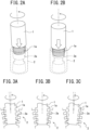
- seizure resistance can be properly evaluated by also simulating a backlash in the initial setting (see FIGS. 2 and 3 ) that is likely to occur in an actual well.
- the initial set position before make-up that is performed by vertical type (the type that makes up a pin and a box in the vertical direction) power tongs 4 is determined on a looser side than conventional.
- the load is applied to the pin 1 by a weight 3. Consequently, this embodiment realizes a more proper seizure resistance evaluation method that takes into account the problem of the applied load by the weight 3 and the problem of "backlash in the initial setting" described above.
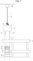
- FIG. 1 illustrates a schematic diagram of the device configuration for a make-up/break-out test in this embodiment.
- the make-up/break-out test is performed with respect to a threaded joint for oil country tubular goods formed by attaching a lower portion of a pin from its upper side to an upper portion of a box 2 placed with its axis directed vertically.
- a pin 1 for test formed by a pin shorter than an evaluation target pin that should be evaluated in the test.
- a male thread of the pin 1 for test has the same structure as a male thread of the evaluation target pin.
- the initial set position is set to a state where five crests of the pin 1 for test or 1/4 of all crests of the pin 1 for test, whichever is greater, or more are exposed from an upper end face of the box 2.
- the initial set position is a make-up start position before make-up, i.e. make-up the pin 1 for test by power tongs 4.
- the weight 3 may be connected to the pin 1. In this case, by lifting the weight 3, it is also possible to adjust the application of the load to the female thread 2a of the box 2 by the mass of the pin 1.
- FIG. 1 shows by way of example the type in which the box 2 is used for fixing a lower portion of the power tongs 4.
- a pin 28 that is tightened by hand is fixed to a lower portion of the box 2 so that the displacement of the box 2 is prevented when the power tongs 4 grip the box 2.
- the pin 28 that is fully made up is used as a fixing position of the lower portion of the power tongs 4.
- the reduction of the applied load is not limited to the case where the applied load by the weight 3 and the pin 1 is controlled to be zero.
- the mass corresponding to the weight may be reduced as described above, or the lifting may be controlled so that the applied load becomes equal to or less than half of the total load of the weight 3 and the pin 1.
- the load reduction amount may be set to be small.
- the present disclosure includes a test that is performed without lifting the weight 3 at the time of break-out.
- turns the number of turns
- torque rapidly increases with a turn near the completion of the make-up. Therefore, in the actual well, the status often occurs where about seven to nine threads are exposed even by tightening to a position that can be achieved by hand. Rather, the status where about one to three threads can be made up after tightening by hand is rare.
- the weight 3 when performing a make-up/break-out test, the weight 3 is slung from above by the heavy equipment (the lifting device 20) such as the crane. Then, the magnitude of the applied load by the weight 3 to be applied to the box 2 side (the female thread 2a side) via the upper portion of the pin 1 for test is adjusted according to the suspension condition of the weight 3 by the heavy equipment 20. For example, at the time of make-up, the hanging chain 21 is loosened to apply the mass of the weight 3 to the box 2 side (the female thread side) via the pin 1. On the other hand, when the load by the weight 3 is not applied or is reduced, it is possible to deal with this by applying tension to the hanging chain 21.
- the load applied to the pin 1 by the weight 3 can be adjusted.
- the present inventors have obtained knowledge that, at the time of make-up, the application of the load to the female thread 2a side of the box 2 results in a severe condition, and that, at the time of break-out, a severe condition is provided in such a way that the weight 3 is in a state of being suspended so as not to apply the mass of the male thread 1a (the pin 1) including the weight 3 to the female thread 2a side so that the swinging around of the pin due to a backlash occurs. In this embodiment, such a state can be simulated.
- the combination of the length of the short pin 1 and the application of the load to the female thread using the weight 3 is also important.
- the length of the short pin 1 is 3000 mm to 5000 mm
- by applying a load equal to or greater than a weight corresponding to a pin raw pipe of 8 m at the time of make-up and by applying the load also at the time of break-out it is possible to simulate a make-up/break-out status using an actual-length pin in an actual well.
- handling in an experiment often becomes slightly difficult.
- the actual laying of a pin is performed by make-up, using the power tongs 4, pins of 8 to 12 m class (25 to 40 ft class) one by one, or a pin formed by connecting two or three pins.
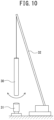
- a pin 30 is made up while being suspended by a wire from above by a crane 32 (see FIGS. 9 and 10 ).
- the load applied to a female thread becomes completely zero. Since it is necessary that the position of the pin shift downward as a male thread of the pin is made up, the status is such that, in the most severe case, all the pin load is applied to the box side on the lower side.
- the pin In the actual laying, when the make-up is loosened, the pin is loosened while being suspended by the wire from above, and therefore, the status is such that the load of the pin 30 is slightly not applied to the box 31 side. However, in the most severe case, the status is such that all the self-weight of the pin 30 is applied to the box 31 side.
- This embodiment is a make-up/break-out evaluation method for a threaded joint for oil country tubular goods composed of the box 2 having the female thread 2a and the pin having the male thread 1a, and is a vertical type make-up/break-out evaluation method in which the axis of the joint is set in the vertical direction. That is, a make-up/break-out test is performed using the power tongs 4 with respect to the threaded joint for oil country tubular goods formed by attaching a lower portion (thread portion) of the pin from its upper side to an upper portion (thread portion) of the box 2 fixed with its axis directed vertically.
- the female thread 2a is set below and the male thread 1a side is set above.
- the lower side corresponds to the coupling (the box 2) and the upper side corresponds to the pin.
- the upper side is the pin.
- a short pin shorter than an evaluation target pin and having the same connection structure as the evaluation target pin is used as the pin 1 for test.
- the pin 1 for test is produced by cutting the evaluation target pin, for example.
- the length of the pin 1 for test is in a range from 600 mm or more to 5000 mm or less and preferably in a range from 600 mm or more to 2000 mm or less, for example.
- the setting to 600 mm or more is determined from approximately the minimum length that can ensure a grip portion of the power tongs 4.
- the setting to 5000 mm or less preferably 2000 mm or less is determined from the limit of the length that can be easily handled.
- the setting to 5000 mm as the upper limit is determined such that since there are many actual-length pins of 8 to 12 m classes (25 to 40 ft classes), 5000 mm is approximately half thereof. The longer, the more it approaches the actual-length pin. In this case, even when the weight 3 is not particularly applied, make-up becomes make-up with the actual-length pin itself, and therefore, there is also an implication of the limit length for handling in a lab experiment.
- a pin of around 1 m (e.g. 600 mm to 1500 mm) is easy to use as the pin 1 for test.
- This length of the pin 1 for test is a length selected for ease of handling, but is an appropriate length also in terms of ease of fixing the weight 3 described below.
- a pin having a configuration in which a plurality of pup joints are connected together may alternatively be used as the pin 1 for test.
- the length on the box 2 side is not particularly specified, a box for use in an actual well itself may be used. It is preferable to perform a test by fixing the pin 1 loosely by tightening by hand so that, when gripping by tongs, a thread surface on the side opposite to the evaluation target side is prevented from being crushed.
- the length of the pin 1 for test is preferably set to a length of 3000 mm or more and 5000 mm or less, for example. This is because the optimal range of the length of the pin 1 for test differs depending on a combination by a load application method, which will be described later.
- the applied load by the weight 3 is not reduced at the time of break-out, i.e. when make-up/break-out is performed with the applied load as it is, it is preferable that the length be equal to or greater than 3000 mm. This is because, in the case of less than 3000 mm, unless the load is reduced by lifting the weight 3 at the time of break-out, there is a possibility that it is not possible to simulate a condition in an actual well more accurately.
- a make-up/break-out test is performed by attaching the weight 3 to the upper portion of the pin 1 for test to apply the load.
- the mass of the weight 3 is set to be equal to or greater than (mass of an evaluation target pin (actual pin) - mass of the pin 1 for test), for example.
- the mass of the weight 3 is set to a mass of an evaluation target pin with a length equal to or greater than 8 m, for example.
- the upper limit value of the mass of the weight 3 is set to three times the mass of the evaluation target pin (actual pin), for example.
- the mass of the weight 3 is defined as a lower limit when, for example, the load applied to the female thread 2a corresponds to a mass corresponding to a mass of an evaluation target pin itself, and for example, a mass corresponding to a case where three evaluation target pins are connected together is defined as an upper limit.
- the reason for attaching the weight 3 of the mass corresponding to the mass of the actual-length pin or corresponding to the three-pin connection is as follows. That is, at the time of actual Make & Break in an actual well, the running operation is performed by make-up one by one in a land well (land rig) so that the self-weight of a single pin is applied at maximum.
- the reason for three pins is that, in a sea well (sea rig), three pins connected together in advance are carried to the rig, and make-up is often performed per three pins in the rig, which is taken into account.
- the mass of the weight 3 for use in a test is preferably a mass that can simulate an applied load that can be applied maximally.
- the mass of the weight 3 is only determined by a crane (heavy equipment) that suspends the pin 1 for test along with the weight 3 and sets it on the box 2. It may be configured to lift the weight 3 by another crane.
- the weight 3 is attached to the upper portion of the pin 1 for test on the side opposite to the make-up side of the pin 1. This is for simulating a status close to an actual status of use of connection by applying the load at the time of make-up.
- the upper portion of the pin 1 is, for example, a position of a thread portion formed on the upper portion side, or a range around it.
- jigs 5 are fixed for attaching the weights 3 to a side surface of the upper portion of the pin 1 for test.
- hooking rods are illustrated as the jigs 5 by way of example. Then, by suspending the weights 3 with respect to the jigs 5 by slings 6 such as ropes or chains, the weights 3 are attached to the upper portion of the pin 1.
- a plate-like block body is illustrated as the shape of the weight 3 by way of example, but the shape of the weight 3 may be another shape. It is preferable that jigs 5 that can be lifted by the crane 20 be provided to the weights 3.
- the actual height position of the weights 3 is not located in the upper portion of the pin 1.
- the position of load application to the pin 1 by the weights 3 (the support position of the weights 3) is located in the upper portion of the pin 1.
- the weight 3 has a billet-like cylindrical shape with a lower surface having a diameter greater than that of the pin 1 for test.
- An upper end portion of an insert rod 10 is integrally fixed to the lower surface of the weight 3 by welding or the like in advance.
- the diameter of the insert rod 10 is set to a diameter smaller than the diameter of an inner diameter surface 1c of the pin 1 for test. It is preferable that a metal fitting 11 that can be lifted by the crane 20 be provided to an upper portion of the weight 3.
- the center of gravity of the weight 3 gets eccentric so as to be displaced in the lateral direction. Further, by the insert rod 10, the weight 3 is hard to fall off the upper portion of the pin 1.
- the length of the insert rod 10 is preferably half or more of the length of the pin 1 for test.
- the weight 3 is attached to the upper portion of the pin 1 so that, in response to swinging around of the pin 1, the position of at least the weight 3 is also displaced (rocks) in the lateral direction (the radial direction of the pin) with respect to the pin 1.
- the applied load to the female thread 2a by the weight 3 can be changed safely and simply according to the swinging around of the pin 1.
- a hanging metal fitting is fixed to a central portion of an upper surface of the weight 3 by welding.
- weights 3 in order to make it possible to evaluate threaded joints of different sizes, it is preferable to prepare a plurality of kinds of weights 3 with various outer diameters and masses.
- the penetration rod 12 is made to pass through the through-hole 10a from one of the passing holes 1d toward the other passing hole 1d.
- the penetration rod 12 has a length such that both end portions of the passing-through penetration rod 12 protrude to the outside from the passing holes 1d, respectively.
- a large-diameter member such as a nut member with a diameter greater than the small diameter of the passing hole 1d may be attached to both end portions or one of the end portions of the penetration rod, thereby using it for preventing coming-off of the penetration rod 12.
- a mass adjustment (increment of the mass) of the weight 3 may be performed by further setting a weight on the side where the hanging metal fitting of the weight 3 is provided.
- the weight adding method and the hooking type or the ring type may be employed.
- the application method of the weight 3 is configured such that, in order to prevent the excessive unbalance of the load to the pin 1, the hanging metal fitting 11 provided to the weight 3 itself and the penetration rod 12 passing through the insert rod 10 attached to the weight 3 are lifted together (see FIG. 7 ).
- the slings 21, 23 such as the sling and the chain with their upper end portions attached to the crane are hung on the hanging metal fitting 11 and both end portions of the penetration rod 12, and the slings 21, 23 are loosened so that the load is applied to the female thread 2a side. Assuming the worst status that the balance is lost, it is preferable to devise to prevent the weight 3 itself from falling down.
- the power tongs 4 are driven to perform make-up of a threaded joint make-up/break-out test. Then, when the male thread 1a moves in a direction of make-up, since the position of the male thread 1a (the position of the pin 1) moves downward, the male thread 1a moves in a direction in which the tension is applied to the chain 21 hung on the weight 3 and the sling 23 such as the sling.
- the structure is preferably such that the chain 21 hung on the weight 3 and the sling 23 hung on the penetration rod 12 are, at their other ends, hung on the hook in the upper portion of the crane independently of each other.
- make-up/break-out of the connection is performed from this state, whether or not (mass of the pin + mass of the weight 3) is applied to the female thread of the box 2 can be determined by monitoring the positional relationship between the passing holes 1d and the penetration rod 12 in the vertical direction.
- FIG. 8A illustrates a state where the load is applied to the crane (a state where all the load is not applied to the female thread of the box)
- FIG. 8B illustrates a state where the load is not applied to the crane (a state where all the load is applied to the female thread of the box).
- the hanging position by the crane 20 is fixed as illustrated in FIG. 7 to start make-up of the connection.
- a state is provided where the penetration rod 12 is not in contact with either an upper end opening portion or a lower end opening portion of each of the passing holes 1d, and the sling 23 attached to the penetration rod 12 has no looseness. From this state, as the connection are made up, the position of the pin 1 is lowered so that the position of the passing hole 1d is displaced downward, but the position of the penetration rod 12 does not change. Therefore, the position of the penetration rod 12 moves upward with respect to the position of the passing hole 1d. Then, when the penetration rod 12 comes in contact with a 12 o'clock position (the upper end position of the opening) of the passing hole 1d (see FIG.
- the "load removal state” referred to in the present disclosure is defined as follows. That is, the range from the state of the applied load being zero until the weight corresponding up to 2 m of the pin 1 for test is applied is defined as the "load removal state".
- the meaning of 2 m is such that, in the case where the length of the pin 1 for test is set in a range from 600 mm to 2 m, as described in Examples given below, 2 m is determined from the upper limit of the length effective for loosening in the "load removal state" at the time of loosening.
- a determination thereof is easily made possible based on the positional relationship of the penetration rod 12 with respect to the passing hole 1d. It can be realized by performing a test while controlling the penetration rod 12 not to contact the 6 o'clock position, and as soon as the penetration rod 12 contacts the 6 o'clock position, returning the penetration rod 12 to the 12 o'clock position.
- the position of setting the male thread 1a of the pin 1 for test with respect to the female thread 2a of the box 2 is also important.
- the state where a backlash of the thread portion is intentionally provided in the state where the load is applied to the upper portion of the pin 1 for test by the weight 3 is set as an initial set position (make-up start position) before make-up.
- make-up start position By make-up the connection using the power tongs 4 from the initial set position, it is possible to simulate an actual connection make-up condition. That is, in this embodiment, the pin is intentionally set at a position not tightened to a tightening position by hand.
- the reason for employing such a loose initial set position at the time of make-up is to simulate a severe condition by realizing a backlash at the time of performing Make & Break.
- the number of crests to be left in the initial set position before make-up is preferably set to be equal to or less than 2/3 of the number of all crests. An evaluation may be performed including the concern about cross threading, and therefore, the condition of only inserting the male thread 1a into the female thread 2a is also included in this application.
- FIG. 9 is a schematic diagram in which Make & Break with a single pin is simulated.
- a compensator 33 and a pin 30 are suspended by a crane 32 to set the pin 30, taking into account that the pin 30 is directed straight to a female thread of a box 31.
- the male thread and the female thread locally abut or do not abut on each other in the initial stage of make-up and in the late stage of break-out. Therefore, uniform load is not applied to the male thread, but strong load is applied only to a part, thus resulting in a severe status.
- a backlash causes the application of the large load from the pin and the application of an offset load due to the male thread being not uniformly made up to locally contact around.
- the make-up position of the pin 1 is set to be loose so as to prevent complete tightening by hand, thereby performing the simulation in this embodiment.
- the length of the pin 1 for test is 3000 mm or more and 5000 mm or less, it is preferable to perform with the weight load being applied both at the time of make-up (at the time of Make-up) and at the time of loosening (at the time of Break-Out).
- This application method is very similar to a status performed in an actual well, but there is a little different portion. It is that the effects of the large load and the offset load are realized by setting, at the pin end portion, the weight 3 equal to or greater than a weight corresponding to the pin raw pipe of 8 m, and by setting the initial set position in the prescribed range.
- a lifting device is provided that can lift at least the weight out of the weight and the pin for test, and the applied load to the female thread of the box from the weight and the pin for test is adjusted (controlled) by lifting by the lifting device.
- the weight is placed on an upper end of the pin for test, the weight includes an insert rod extending downward from a lower surface of the weight and loosely inserted in the pin for test, the weight includes a penetration rod protruding laterally from the insert rod and protruding outward through a passing hole formed in the pin for test, and the diameter of the passing hole is greater than the diameter of the penetration rod.
- the weight can be swingably attached to the upper portion of the pin, and further, by lifting the weight, the pin can also be lifted. That is, it is possible to configure that the load to the female thread by the pin can also be reduced.
- Example 1 is an example that indicates that a make-up/break-out test in the state where the mass of a weight is applied to a female thread via a pin based on the present disclosure can simulate Make & Break with an actual-length pin.
- the attaching of the weight employs the type of "Attaching Example 2" as illustrated in FIG. 7 , in either case. This also applies to the other Examples.
- C-4 an actual-length pin was used. Further, C-4 is a case where a make-up/break-out test was performed under a conventional condition in which a weight was not used and an initial set position (make-up start position) was set to a state completely tightened by hand (hereinafter referred to as the conventional position).
- This C-4 is an example (seizure occurred at the fourth time) in which the number of M/B times was three so that an evaluation was a pass. This was made to be a determination criterion in Example 1.
- the mass of the actual-length pin was about 1.0 ton (metric ton).
- the weight of a short pin is about 110 kg with a length of 1 m.
- C-1 to C-3 were each an example in which, based on the present disclosure, make-up/break-out by the power tongs 4 were performed in the state where an initial set position (make-up start position) was set to a state loosely tightened by hand (hereinafter referred to as the loose position), and the load was applied by a weight to a pin for test.
- the initial set position (make-up start position) is indicated as "pin set position before make-up”.
- A-1 to A-6 shown in Table 2 in order to evaluate the structure of a newly designed threaded joint, the seizure resistance was evaluated using a Q125 carbon steel based material of 13-3/8" 72.0# size.
- the connection designs of the samples had the same structure, i.e. the same connection structure.
- Example 2 Specific connection design outlines in Example 2 are as follows.
- A-4 an actual-length pin was used. Further, A-4 is a case where a make-up/break-out test was performed under a conventional condition in which a weight was not used and an initial set position (make-up start position) was set to a conventional position.
- A-4 is an example in which the seizure resistance of the new connection design was tested by preparing the actual-length pin. This becomes a determination criterion and an actual well condition.
- the seizure occurred after the third break-out.
- An initial make-up set position was a position where 10 pin crests were exposed, which was thought to be a plausible position as a practical make-up position often observed in an actual well. Since, structurally, the actual-length pin is sometimes inserted slightly obliquely no matter how much it is devised, 10 threads were the limit of tightening by hand in the example this time.
- A-4 is an example in which the seizure occurred at the third time of the number of M/B times so that an evaluation was a fail. This was made to be a determination criterion in Example 2.
- a test was performed by using a short pin as a pin for test and setting an initial set position before make-up to a conventional position completely tightened by hand.
- a coupling/pin axis adjustment was performed well by horizontal type tongs. Since the short pin was used, handling was easy for both the horizontal type and vertical type tongs, and therefore, it was possible to perform make-up to a degree where about two to three pin crests were exposed, i.e. to a position completely tightened by hand at a glance. Then, from that position, make-up by the power tongs 4 was performed.
- A-1 is a horizontal type test and is an example in which the test was performed in the status where no load was applied to the threads at the time of make-up and at the time of break-out, and Make & Break was achieved six times. In A-1, the test was intentionally completed by 6 times of Make & Break.
- a casing member is on the pass level if M/B can be performed three times, and therefore, it is seen that it was the level exceeding it by far. That is, the deviation from the evaluation of A-4 is large.
- A-2 is an example that simulates a conventional vertical type test. While A-1 was in the status where the self-weight of the short pin was not applied to the coupling connection, A-2 was in the status where since the test was performed with the pin standing upright, the self-weight of the short pin was applied to the crest of the coupling. This means a status where even the short pin has a self-weight of about 110 KG with this size, and this is applied to the coupling crest.
- A-3 is an example in which NPL 2 was simulated so that a make-up/break-out test was performed by disposing a weight of 510 KG weight at an upper portion of a pin.
- A-3 although the number of M/B times was reduced to four (seizure occurred at the fifth time), an evaluation of the test was a pass evaluation, and therefore, A-3 is determined to be a design having the seizure resistance that satisfies the required level of API 5C5: 2017.
- A-5 a short pin of 600 mm was employed as a pin for test. Then, a make-up/break-out test was performed based on the present disclosure under the condition where an initial set position (make-up start position) was set to a loose state with seven threads exposed, and a load corresponding to 1 ton (corresponding to 9 to 10 m) of a single actual-length pin was applied by a weight, with its results shown. The pin along with the weight were lifted at the time of break-out so that the applied load from the weight 3 and the pin to a female thread was controlled to near zero at the time of break-out.
- A-6 is an example in which make-up was started in the state where an initial set position (make-up start position) was set to a conventional position with one thread exposed.
- Example 3 is an example that indicates that a make-up/break-out test in the state where the mass of a weight is applied to a female thread via a pin based on the present disclosure can simulate Make & Break with an actual-length pin.
- Example 3 with respect to the samples (B-1 to B-6) shown in Table 3, the seizure resistance was evaluated using a L80-13Cr steel chrome steel based material of 9-5/8" 53.5# size in JFELION TM (registered trademark).
- the connection designs of the samples had the same structure, i.e. the same connection structure. Specific connection design outlines in Example 3 are as follows.
- Example 3 an evaluation of a developed solid lubricant was performed using a make-up/break-out test.
- a solid lubricating film was formed on Cu-Sn alloy plating.
- the solid lubricating film was mainly composed of a compound obtained by developing Teflon (registered trademark) in a polyamideimide/polyimide composite binder resin, and a film was formed at a burning temperature of 200 to 300°C.
- Teflon registered trademark
- water-based acrylic was applied and dried by farinfrared light to form a film.
- B-1 is a case where the load is applied by a weight, but an initial set position before make-up was set to a conventional position completely tightened by hand.
- B-2 is an example in which the condition was the same as the condition of B-1 except that an initial set position before make-up was set to a loose position.
- B-3 is an example in which, compared to B2, a pin for test was set to 2000 mm, and the condition was changed to a condition to reduce the applied load at the time of break-out.
- a test was a severe test in which the weight 3 with a sufficient weight was applied, and a backlash was generated at the time of make-up/break-out, wherein the seizure occurred on the third time in a make-up/break-out test so that a fail was determined. That is, the evaluation was equivalent to the number of M/B times being two in B-4, and therefore, it has been seen that it is possible to obtain the evaluation equivalent to the evaluation in the test using the actual-length pin.
- B-6 is an example in which a make-up/break-out test was performed under the same condition as B-4 except that use was made of a solid lubricant that was further improved with respect to a solid lubricant that was determined as a fail in the evaluation of B-4.
- the number of M/B times was 5 or more so that the evaluation was determined as a pass.
- B-5 a test was performed under the condition of B-3 except that the solid lubricant used in B-6 was used, and as a result, the number of M/B times was 5 so that an evaluation was determined as a pass.
Landscapes
- Physics & Mathematics (AREA)
- General Physics & Mathematics (AREA)
- Engineering & Computer Science (AREA)
- Life Sciences & Earth Sciences (AREA)
- Mining & Mineral Resources (AREA)
- Geology (AREA)
- Geochemistry & Mineralogy (AREA)
- Fluid Mechanics (AREA)
- Environmental & Geological Engineering (AREA)
- General Life Sciences & Earth Sciences (AREA)
- Mechanical Engineering (AREA)
- Chemical & Material Sciences (AREA)
- Analytical Chemistry (AREA)
- Pathology (AREA)
- Immunology (AREA)
- Health & Medical Sciences (AREA)
- General Health & Medical Sciences (AREA)
- Biochemistry (AREA)
- Investigating Strength Of Materials By Application Of Mechanical Stress (AREA)
- Testing Of Devices, Machine Parts, Or Other Structures Thereof (AREA)
- Non-Disconnectible Joints And Screw-Threaded Joints (AREA)
Abstract
Description
- The present disclosure is a technology relating to a make-up/break-out evaluation method for a threaded joint for oil country tubular goods that is performed when evaluating the seizure resistance at the time of make-up/break-out of the threaded joint for oil country tubular goods.
- In this description, there are cases where a pipe having a female thread will be collectively referred to as a box. That is, a coupling will also be described as one type of box.
- With respect to a threaded joint for oil country tubular goods, the design of the threaded joint and the seizure resistance of the threaded joint are evaluated through a make-up/break-out test (Make & Break test) using power tongs. The seizure resistance is evaluated as to whether or not a surface treatment and a lubrication condition of the threaded joint are properly set.
- The seizure resistance of the threaded joint for oil country tubular goods is described in the API 5C5 standard. In the API 5C5 standard, it is required that, in the case of a casing size, two times of make-up/break-out and final make-up, i.e. make-up up to three times, can be performed. On the other hand, it is required that, in the case of a tubing size, nine times of make-up/break-out and final make-up, i.e. make-up up to ten times, can be performed. Hereinafter, "make-up/break-out" will also be referred to as "Make & Break".
- Evaluation of the surface treatment and lubrication of a joint portion at the time of make-up of the threaded joint for oil country tubular goods is performed as follows, for example. That is, in the case where the threaded joint is a T & C (Threaded and Coupled) type threaded joint, when a raw pipe is carbon steel based, a Mn phosphate chemical conversion coating, for example, is formed on the coupling side (box side) and thread cutting is left as it is on the pin side or shot blast is applied to the surface thereof for the evaluation described above. Then, a compound is applied to the surface on at least one of the coupling side and the pin side, and thereafter, a make-up/break-out test is performed to evaluate the occurrence of seizure. On the other hand, when a raw pipe is stainless steel based or high alloy based such as a Ni-based alloy, the evaluation is performed by forming, for example, electroplating on a coupling (box), applying a compound in the same way as described above, and performing a make-up/break-out test. The electroplating is formed by a layer of Cu plating or other metal plating, for example.
- On the other hand, in the case where the threaded joint is an integral type threaded joint, chemical conversion coating or electroplating for lubrication is applied to at least one of threaded joints and a compound is applied to the threaded joint or the threaded joints on one side or both sides for the evaluation described above. Then, a make-up/break-out test is carried out to perform the evaluation. Herein, the integral type threaded joint is a threaded joint of the type in which connection is achieved with one side of a pin serving as a male thread and the other side of the pin serving as a female thread, without using a coupling like a semi-flush threaded joint or a flush threaded joint.
- Herein, in the case of a casing, the length of an actual pin is 25 to 34 feet (7.62 m to 10.36 m) in Range-2 and 34 to 48 feet (10.36 m to 14.63 m) in Range-3, for example. In the case of a tubing, the length of an actual pin is 28 to 32 feet (8.53 m to 9.75 m) in Range-2 and 38 to 42 feet (11.58 m to 12.80 m) in Range-3, for example.
- Assuming that the make-up/break-out test is performed using such a pin with the actual length, when evaluating the adequacy of the design of the threaded joint and the surface treatment and lubrication of the threaded joint, the evaluation is performed in a state closer to a condition of actual use. However, in this case, there is a problem that facilities where the test can be done are limited. Further, there is a problem that the longer the pin, the more cost and time are required. Further, there is actually no case where some newly developed connection member (pin or the like) is brought to an actual well and used without performing a lab verification test.
- Therefore, there are cases where a so-called short pin (Pup Joint), machined to a length of about 1 m, is produced and a make-up/break-out test is performed using the produced short pin, thereby evaluating whether or not the pin and so on meet the criteria of the seizure resistance described above.
- Herein, as the make-up/break-out test, there are a horizontal type test in which the axes of pipes (pipes) for the test are aligned horizontally, and a vertical type test in which the axes of pipes for the test are aligned vertically.
- The horizontal type test described above is a test that purely evaluates the seizure resistance between a female thread (example: a thread portion of a coupling) and a male thread (example: a treaded portion of a pin). The horizontal type test is a test that evaluates the seizure resistance under ideal conditions in which there is almost no misalignment (misalignment (Misalignment) in the XY plane) of the axes of the female thread and the male thread.
- On the other hand, in the vertical type test, the self-weight of a short pin is applied to a female thread (example: a thread portion of a coupling). The vertical type test is a test in which make-up/break-out is performed in the state where, in the case of, for example, a 1 m short pin of 9-5/8" × 53.5#, a load of about 80 kg is applied to a female thread (example: a thread portion of a coupling) being set below. In the case of the vertical type test, in the initial set position, the state is such that the pin is set in an upper portion of the coupling from the upper side. Therefore, the axis center positions of the coupling and the pin cannot always be set to coincide with each other. That is, as illustrated in
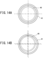
FIG. 14B , in the vertical type test, there is a tendency in the initial setting that the pin is subjected to misalignment of its axis in the horizontal plane and is in a state of oblique setting in the thread advancing direction, resulting in that the center axis of ashort pin 40 is misaligned with respect to abox 41.FIG. 14A illustrates a state where the center axes of thebox 41 and theshort pin 40 coincide with each other. Therefore, make-up is performed such that it starts from the eccentric state and converges in a direction to make the axis centers coincide with each other. In this case, it cannot be avoided that the connection is made up while locally abutting hard on each other. - As illustrated in
FIG. 13A , as theshort pin 40 increases in length, the tendency also increases that the axis of theshort pin 40 is set to be oblique at a predetermined angle θ with respect to thebox 41. As illustrated inFIG. 13B , as theshort pin 40 increases in length, there is also a tendency that the axis of theshort pin 40 is bent more. - Therefore, in the vertical type test, high load is locally applied to the female thread of the
box 41, including that the self-weight of the short pin is locally applied to the female thread. Therefore, the test becomes severe. For this reason, it has been general perception that evaluation by the vertical type test is important. - However, there has been a problem that even when a pass is determined in a vertical type test using a short pin, the seizure often occurs in a joint portion when a make-up/break-out test is performed using a pin with an actually used length or when applied in an actual well (site). In particular, such a problem is outstanding in a test (evaluation) of new connection design, new surface treatment coating, new lubrication coating, or the like.
- Herein,
PTL 1 describes that an axial misalignment (angular misalignment) tends to occur in the first make-up, and describes an evaluation of the seizure resistance based on such an assumption. That is,PTL 1 describes an evaluation based on the assumption of an axial misalignment with an inclination of about 10 degrees, for example. This is also a kind of severe test condition. - However, the inclination of the axis of the pin by as much as 10 degrees is unlikely to occur in the state where crest of the joint are engaged, even taking into account the taper of a connection for oil country tubular goods. The inclination of the axis at such an angle is on a level that is only realized in a partial contact state where the thread portion is not exactly engaged so that the pin is merely inclined. In addition, such a condition is far from the actual well condition and corresponds to a case where cross threading is caused, for example. The cross threading means that the threads are made up with a misalignment of one step from the original position.
- Therefore, the test described in
PTL 1 is a test that is far different from the use in the actual well. Alternatively, the test described inPTL 1 is a test in the partial contact state before the engagement of the crest in the first make-up. - Further, even if the make-up test is performed by providing the significant inclination at first, the thread of the pin, while engaging with the thread of the coupling, moves to the normal position with its axis standing upright. Therefore, providing the inclination of 10 degrees at the beginning of the make-up cannot be thought to be a meaningful test condition.
- On the other hand, there is also a method of performing a make-up/break-out test by connecting a plurality of short pins to achieve a length corresponding to less than an actual length of an evaluation target pin. This is a method of performing the test while connecting vertically three to four short pins each of 3 m class (about 10 ft), for example. In the case of achieving the length corresponding to the pin (corresponding to a length < 12 m; < 40 ft) while performing making up (Make-up) per short pin, the difficulty of lifting the pin is solved. However, whether or not even a test in the state where the mass corresponding to the pin is applied can be reproduced is determined by the height of a ceiling of a test site. Further, the rigidity of the pin for test is increased corresponding to the presence of couplings, connecting the short pins, at intermediate portions in the axial direction. Then, corresponding thereto, there is a tendency that the connected short pins are set straight with respect to a box. Therefore, in this case, it cannot be said that a simulation is performed in which the self-weight of the pin is locally applied to a female thread portion of the box inevitably, taking into account that the axis of the actual pin tends to be slightly bent.
-
NPL 2 describes an example of performing a make-up/break-out test by disposing a weight of 5 kN (= 510 kg weight) as a deadweight (Deadweight) right above a pin in order to study the influence of the self-load of a casing on make-up torque behavior. In the example described inNPL 2, a pin of 9-5/8" × 53.5# and a coupling corresponding thereto are prepared to confirm the effectiveness of the experiment. The inventors performed a test by simulating it, i.e. by preparing a pin made of carbon steel and so on, applying Mn phosphate chemical conversion coating as a surface treatment of a coupling, applying shot blast to the surface of the pin, and using a device simulating the technology ofNPL 2. In this event, after applying a general compound to threaded joints on both sides of the pin, tightening by hand was performed to a position where it stopped, as an initial set position before make-up (a set position before make-up by power tongs). That is, a make-up/break-out test was performed from the state where the make-up was performed to the state with one to three crests remaining from an end face of the coupling. As a result of the test, three times of Make & Break was able to be performed, which was regarded as a pass determination. Next, evaluation was performed by shifting it to a conventional lab test using a pin with an actual length, and as a result, the seizure occurred on the threads. From this, even if the condition that can obtain a pass is found out in the evaluation test based on the conventional technology, there is a possibility that the seizure occurs by using the pin with the actual length. Therefore, according to the studies of the inventors, it has been found that a method of evaluating the seizure resistance when using the pin with the actual length is not clarified with this conventional technology. - Herein, a make-up/break-out test other than in a usual rig is performed indoors with limited ceiling height. Therefore, conventionally, in a test using vertical tongs, use is made of a pin that is much shorter than a pin employed in an actual well. When a test is performed using a pin with a length that is used in an actual well, horizontal type tongs are often used.
- In these evaluation methods, make-up is performed after temporary fixing is performed to a status where threads are exactly engaged with each other by tightening the short pin by several turns or more in a manually turnable range by hand before the make-up by the power tongs. That is, conventionally, the make-up by the power tongs is performed after the completion of the substantial axis alignment. On the other hand, in an actual well site, use is made of a pipe of, for example, 12 m, which is longer than the short pin in the lab. In addition, tightening by hand is performed only by several turns, and in the most severe case, tightening by hand is often omitted. Therefore, in the actual well site, it has been imagined that the misaligned engagement and the misalignment at the beginning of the make-up become significant, resulting in severe make-up condition. However, the causal relationship of make-up behavior is complicated, and conventionally, in order to make an evaluation by the lab, it is the actual situation that there is no other method but to merely set a pass determination line of the number of times of make-up/break-out to be more. Actually, a method of a severe test in a lab test is usually not in operation.
- PTL 1:
JP 2002-327874 A -
- NPL 1: API RP 5C5 Latest Edition (4th Edition, January 2017): Procedures for Testing Casing and Tubing Connections
- NPL 2: Tsuru et al.: Journal of the Japanese Association for Petroleum Technology, Vol. 61, No. 6, (1996), pp. 527-536
- The present disclosure has been made in view of the points described above and has an object to provide a make-up/break-out evaluation method for a threaded joint for oil country tubular goods that makes it possible to evaluate the seizure resistance of the threaded joint for oil country tubular goods accurately without performing a test using a threaded joint with an actual length.
- In order to solve the problems, the gist of the present disclosure is a make-up/break-out evaluation method configured to perform make-up/break-out by power tongs with respect to a threaded joint for oil country tubular goods including a box having a female thread and a pin having a male thread, wherein the make-up/break-out evaluation method includes: when performing a make-up/break-out test with respect to the threaded joint for oil country tubular goods formed by attaching a lower portion of the pin to an upper portion of the box placed with an axis directed vertically, using, as the pin for use in the test, a pin for test formed by a pin shorter than an evaluation target pin; attaching a weight to an upper portion of the pin for test and setting a mass of the weight to be equal to or greater than a mass obtained by subtracting a mass of the pin for test from a mass of the evaluation target pin; and setting an initial set position to a state where five crests of the pin for test or 1/4 of all crests of the pin for test, whichever is greater, or more are exposed from an upper end face of the box, the initial set position being a make-up start position before make-up, the make-up configured to make up the pin for test by the power tongs.
- The evaluation target pin is, for example, a pin with a length that is actually used in an actual well.
- According to the present disclosure, even when a test is performed using a pin for test that is shorter than a pin with an actual length (an evaluation target pin), it is possible to evaluate the seizure resistance of a threaded joint for oil country tubular goods more accurately.
-
-
FIG. 1 is a schematic diagram illustrating the facility configuration for a make-up/break-out test according to an embodiment based on the present disclosure; -
FIG. 2A and 2B are diagrams for explaining a backlash according to an initial set position; -
FIG. 3A to 3C are diagrams for explaining a backlash between a male thread and a female thread; -
FIG. 4 is a diagram for explaining an example of attaching weights to an upper portion of a pin; -
FIG. 5 is a diagram for explaining an example of attaching a weight to an upper portion of a pin; -
FIG. 6 is a diagram for explaining an example of attaching a weight to an upper portion of a pin; -
FIG. 7 is a diagram illustrating the relationship between an insert rod and a penetration rod, and a pin; -
FIG. 8A and 8B are diagrams illustrating the relationship between a penetration rod and a passing hole; -
FIG. 9 is a schematic diagram of make-up of connection in an actual well; -
FIG. 10 is a schematic diagram of make-up of connection in an actual well; -
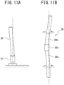
FIG. 11A and 11B are diagrams illustrating the behavior of a pin; -
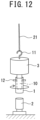
FIG. 12 is a diagram illustrating a pin in a test; -
FIG. 13A and 13B are diagrams illustrating an example of bending of a pin due to axial misalignment; -
FIG. 14A and 14B are diagrams illustrating the relationship between the center axes of a pin and a box in the initial setting of a threaded joint; -
FIG. 15 is a diagram illustrating an example of the relationship between turns and torque at the time of make-up by power tongs in an evaluation method based on the present disclosure; and -
FIG. 16 is a diagram illustrating an example of the relationship between turns and torque at the time of make-up by power tongs, which is often observed in a conventional lab evaluation method. - Next, an embodiment of the present invention will be described with reference to the drawings.
- Herein, inasmuch as there is no reason for convenience, the same constituent elements will be described by assigning the same sign to them. In each of the drawings, there are cases where the thicknesses and the ratio of the constituent elements are exaggerated and where the number of the constituent elements is also illustrated differently from an implemented product. Further, the present disclosure is not limited to the following embodiment, and as long as it does not depart from the gist thereof, the present disclosure can be embodied with an appropriate combination or a modification, and a mode added with such a modification or improvement can also be included in the present disclosure.
- Conventionally, there is the fact that, with respect to the new thread shape design of a threaded joint for oil country tubular goods and the surface treatment (plating, chemical conversion treatment) and the lubrication method (compound, solid lubricant) for a threaded joint for oil country tubular goods, the adequacy thereof cannot be confirmed without verification of the seizure resistance by a test using a pin with an actual length before putting on the market. However, according to the studies of the inventors, as described above, it has been found that even the method of evaluation by the severe test cannot achieve a proper evaluation with the conventional technology using the short pin.
- Herein, the method described in
NPL 2 is merely a method of simply placing a weight on an upper end portion of a pin. Therefore, in the method described inNPL 2, a severe make-up/break-out condition corresponding to an actual well as intended by the present disclosure cannot be simulated. The process of make-up/break-out in a make-up/break-out test is performed by power tongs from a make-up start position (initial set position) after tightening by hand. - The reason why the simulation cannot be performed as described above is as follows.
- (a) First, with the applied load by the weight of the mass of 510 kg described in
NPL 2, when a short pin is used, there is a possibility that the test does not become a severe test because of the loaded mass being too small. In particular, there is such a tendency when the diameter of the pin is large. - (b) Next,
NPL 2 does not specify an initial set position (make-up start position) at the time of each make-up. However, in a conventional make-up/break-out test, make-up/break-out is repeated by power tongs after make-up to a degree that can be done maximally by tightening by hand. That is, conventionally, the initial set position before each make-up is a position tightened maximally by tightening by hand. However, in this case, it is not possible to simulate a phenomenon in which a pin swings around due to a backlash that occurs by loosely setting the pin, which is usually often observed in an actual well. In a recent actual well, a pin is often set on a box connection by remote control using a machine with no touch. Further, it is also often that make-up by power tongs is performed from the state where the pin is almost merely fitted in from above. Therefore, it has to be said that the method ofNPL 2 is far from the make-up condition of the actual well. - On the other hand, in this embodiment, an initial set position before make-up, i.e. at the time of make-up by power tongs, is loosely set intentionally. Consequently, the make-up is performed while a pin is swinging around so that the make-up by the power tongs is performed under a condition close to an actual well condition.
- Herein, the behavior of torque in make-up by vertical type power tongs will be described in detail using
FIGS. 15 and 16. FIG. 15 is a torque/turn chart example in the case where make-up from the state where the initial setting is loose is performed based on the present disclosure. On the other hand,FIG. 16 is a torque/turn chart example in a conventional vertical type test. - In the case of the make-up by the power tongs based on the present disclosure, the pin is made up via regions (stages) (x), (y), and (z) in this order as illustrated in
FIG. 15 . On the other hand, in the conventional lab make-up test, the pin is made up via regions (stages) (y) and (z) in this order, not via a region (x). The inventors have confirmed that the relationship between turns and torque at the time of make-up by power tongs in an actual well becomes a graph that is approximate to the relationship between turns and torque illustrated inFIG. 15 . - The region (x) illustrated in
FIG. 15 is a phenomenon that is observed when a pin connection is loosely made up to a box connection. It is an ideal state in the region (x) that the pin connection is made up to the box connection so as to be engaged with the box connection with no interference therebetween. That is, in the region (x), the make-up should be in a state with no torque generated normally, but as a result of various experiments and so on by the present inventors, knowledge has been obtained that a number of spike-like torques are generated in the make-up in the region (x) as illustrated inFIG. 15 . This is presumably because, in the region (x), the pin connection is misaligned with respect to the axis of the box connection so that the pin connection and the box connection locally abut on each other while make-up the pin connection to the box connection. Further, it is conceived that the actual well is affected by various conditions such as weather like wind and rain, offshore, desert, and cold district. This leads to a thought that the state where a number of spike-like torques are generated in the make-up in the region (x) as illustrated inFIG. 15 simulates the state in the actual well more properly. - Further, the present inventors have also obtained knowledge that, in a vertical type test using a short pin, when make-up is performed by applying a pin weight corresponding to an actual length to the short pin, the generation of spike-like torques increases in the make-up in the region (x).
- After the region (x), the threads go through the region (y), i.e. a lubrication state until the threads come in complete contact with seal portions (see
FIG. 15 ). Although it depends on the design of the connection for oil country tubular goods, the region (y) corresponds to about one to two turns. Then, after coming in complete contact with shoulders, the pin connection turns in the region (z), i.e. from the state in contact with the shoulders, so that the torque rapidly increases to make up the connection finally. - As described above, the make-up in the region (x) illustrated in
FIG. 15 can occur in the actual well. From the knowledge described above, the region (x) causes deformation or breakage of the crest, breakage of a Mn phosphate layer or a metal plating layer as a base, or impediment to uniform development of an applied compound to induce development unevenness of the compound. Further, in the case of a solid lubricant film, the region (x) causes breakage or peeling of the film. Therefore, it is seen that concern increases that the pin connection is damaged not a little along with damage to the box connection. Based on the knowledge described above, the present disclosure presents a simulatable test by applying the load to the short pin and loosely setting the initial make-up start position. - On the other hand, as illustrated in
FIG. 16 , in a state tightened to the limit by tightening by hand, there is no make-up in the region (x), and make-up is performed only in the regions (y) and (z). Therefore, this merely simulates the lubrication until reaching a state in complete contact with the shoulders, and therefore, it is hard to say that what is occurring actually is fully simulated. When the load is applied to the pin in this state, the make-up is performed with the axis of the pin being straight with respect to the box connection. Therefore, the lubrication becomes rather stable with the load applied to the pin. As a result, the test is evaluated to be excessively good such that the lubrication characteristics are stable and that the number of M/B times is large. - Through the studies described above, the inventors have obtained knowledge that it is possible to reproduce a severe make-up condition thought to be unique to an actual well, by devising a very early state of thread make-up in which torque is not usually measured, or devising make-up/break-out weight conditions, without using a long pin (an evaluation target pin) for use in the actual well. Further, knowledge has also been obtained that, by adjusting the load by a weight applied to a pin, it is possible to show that the disturbance of torque in very early make-up relates to the later disturbance of torque or flaws of thread surfaces.
- Herein, the torque turn chart is a determination method that makes it possible to understand characteristic evaluation at the time of make-up/break-out most simply. Even when this chart is normal at first glance, there are cases where flaws occur on the threads due to repeated make-up and so on. On the other hand, when this value starts to increase at a stage where make-up is looser than usual, it is possible to determine that make-up is not performed normally.
- (c) The third problem of
NPL 2 is the load condition of a weight at the time of break-out. - Further, the present inventors have obtained knowledge through various experiments that when loosening threads after make-up is performed by loosely setting an initial set position intentionally to allow a pin to easily swing around at the time of the make-up, it is possible to simulate a status that is more severe than a status close to an actual well when a weight is not placed or the load applied from the pin and the weight to the female thread is lower.
- That is, in the method described in
NPL 2, when loosening (break-out) threads, the load by a weight is dispersed symmetrically and uniformly and applied to the axis center of the thread of a short pin. Therefore, the engagement state of the threads is rather stabilized. Then, the threads are loosened straight from a made up position without causing a backlash. As a result, in the method described inNPL 2, it is hard for the pin to swing around so that it is not possible to properly simulate the occurrence of the seizure at the time of break-out that is likely to occur in an actual well. Depending on the status, a status may occur that misleads that the lubrication characteristics are good. Taking this into account, the inventors have obtained knowledge that, at the time of break-out in which a pin often swings around in an actual well, it is preferable as a more accurate simulation of an actual well condition that the load that is applied to the pin be reduced intentionally so that, where possible, the load by a weight is almost not applied so as to provide a state where the pin easily swings around. - Therefore, in this embodiment, taking this into account, the load is applied by a weight to a pin for test at the time of make-up. Further, the applied load by the weight is reduced at the time of break-out. The weight applied at the time of the make-up takes into account that the pin weight is applied to a box connection (female thread) in an actual well. On the other hand, the reduction of the applied load by the weight at the time of the break-out is for simulating a backlash of a pin connection that is likely to occur in break-out in an actual well.
- Naturally, the present disclosure includes a case where the reduction of the applied load by the weight is not performed at the time of the break-out. Even in that case, this embodiment makes it possible to perform an evaluation more accurately than conventional. Certainly, even if the load is not removed at the time of the break-out, it is possible to reproduce the load to a thread surface of the body of a long pipe in an actual well by the use of the weight at the time of the make-up. Therefore, the present disclosure enables an evaluation closer to an actual well compared to a general conventional make-up method.
- Herein, in a test with a short pin in a horizontal type test, there is no influence of the self-weight of the pin on a threaded joint. Even in a test with a short pin in a vertical type test, when a weight is not used, only a weight corresponding to about 1/10 of a length of an actually used pin (an evaluation target pin) is applied to a female thread of a box. Assuming that the actual pin is about 8 to 12 m, the short pin is often about 1 m.
- On the other hand, under the most severe condition in an actual well, Make & Break is performed using a pin formed by connecting three pins, for example. Therefore, it is preferable to perform a test by taking into account the load in the three-pin connected state to estimate the weight of the actual pin (see
FIG. 11B ; an example of two-pin connection). That is, it is preferable to be able to simulate that the load from a load applied in an actual well to a more severe load is applied to stabbing flanks. The stabbing flanks are surfaces that come in contact with each other when the threads are on the make-up side, and that correspond to vertical walls of the female thread and the male thread. These surfaces are neither a crest surface nor a bottom surface, but are inclined surfaces of the threads that come in contact with each other while being on the make-up side. - It is important to consider not only the mere applied load as described above, but also the effect of a backlash. That is, the seizure resistance can be properly evaluated by also simulating a backlash in the initial setting (see
FIGS. 2 and 3 ) that is likely to occur in an actual well. - Herein, as illustrated in
FIG. 2A , when apin 1 is merely placed (stuck) in an upper portion of abox 2, this results in a state where about half of crests of amale thread 1a of thepin 1 are exposed from the box. Therefore, the pin tends to backlash when made up by power tongs. On the other hand, as illustrated inFIG. 2B , as the make-up proceeds, the backlash of thepin 1 in the make-up decreases. As illustrated inFIG. 3 , there is always a backlash structurally in the joint due to the taper of the crest of the pin. - Taking the above into account, in this embodiment, even when a pin shorter than an evaluation target pin is used as the
pin 1 for test, i.e. the pin for use in the test, the initial set position before make-up that is performed by vertical type (the type that makes up a pin and a box in the vertical direction)power tongs 4 is determined on a looser side than conventional. Further, in this embodiment, the load is applied to thepin 1 by aweight 3. Consequently, this embodiment realizes a more proper seizure resistance evaluation method that takes into account the problem of the applied load by theweight 3 and the problem of "backlash in the initial setting" described above. -
FIG. 1 illustrates a schematic diagram of the device configuration for a make-up/break-out test in this embodiment. - In this embodiment, the make-up/break-out test is performed with respect to a threaded joint for oil country tubular goods formed by attaching a lower portion of a pin from its upper side to an upper portion of a
box 2 placed with its axis directed vertically. In the test, as the pin for use in the test, use is made of apin 1 for test formed by a pin shorter than an evaluation target pin that should be evaluated in the test. A male thread of thepin 1 for test has the same structure as a male thread of the evaluation target pin. - Further, a
weight 3 is attached to an upper portion of thepin 1 for test. The mass of theweight 3 is set to be equal to or greater than the mass obtained by subtracting the mass of thepin 1 for test from the mass of the evaluation target pin, or simply set to be equal to or greater than the mass of the evaluation target pin. - The initial set position is set to a state where five crests of the
pin 1 for test or 1/4 of all crests of thepin 1 for test, whichever is greater, or more are exposed from an upper end face of thebox 2. - The initial set position is a make-up start position before make-up, i.e. make-up the
pin 1 for test bypower tongs 4. - In this embodiment, it is possible to lift the
weight 3 using a crane or other lifting device 20 (heavy equipment).Sign 21 denotes a chain serving as a sling for the crane. By making it possible to lift theweight 3, it is possible to adjust the application of the load by theweight 3 to afemale thread 2a of thebox 2 via thepin 1. - In this event, the
weight 3 may be connected to thepin 1. In this case, by lifting theweight 3, it is also possible to adjust the application of the load to thefemale thread 2a of thebox 2 by the mass of thepin 1. - The example of
FIG. 1 shows by way of example the type in which thebox 2 is used for fixing a lower portion of the power tongs 4. In that case, apin 28 that is tightened by hand is fixed to a lower portion of thebox 2 so that the displacement of thebox 2 is prevented when the power tongs 4 grip thebox 2. On the other hand, according to the type of power tongs, there are cases where thepin 28 that is fully made up is used as a fixing position of the lower portion of the power tongs 4. In the present disclosure, there is no limitation to a fixing method for the lower portion of the power tongs 4. - In this embodiment, when make-up by the power tongs 4, the
chain 21 is set to a loose state (non-lifting state) so that the mass of theweight 3 and thepin 1 is applied to thefemale thread 2a. On the other hand, when break-out by the power tongs 4, theweight 3 is lifted by thechain 21 so that the applied load to thefemale thread 2a by theweight 3 is reduced. In this event, when theweight 3 and thepin 1 are connected together, the applied load to thefemale thread 2a by thepin 1 can also be reduced. The reduction of the applied load controls a lifting state by thecrane 20 in such a way that the mass of theweight 3 and thepin 1 is not applied to thefemale thread 2a, for example. The reduction of the applied load is not limited to the case where the applied load by theweight 3 and thepin 1 is controlled to be zero. For example, the mass corresponding to the weight may be reduced as described above, or the lifting may be controlled so that the applied load becomes equal to or less than half of the total load of theweight 3 and thepin 1. - Only the lifting by the
crane 20 for load reduction makes it possible that the posture of thepin 1 at the time of break-out is made unstable. Therefore, the load reduction amount may be set to be small. - Herein, the present disclosure includes a test that is performed without lifting the
weight 3 at the time of break-out. - Herein, in general, in a make-up/break-out test using a short pin, since it is possible to perform make-up with less misalignment of the axes of the
male thread 1a and thefemale thread 2a, tightening by hand can be performed to a position where about one to three or less crests of thepin 1 are exposed. When the make-up/break-out test is performed from this position using the power tongs 4, even when thepin 1 has a large diameter size such as 9-5/8" or 13-3/8", the seizure is hard to occur. However, as in this embodiment, in the case where tightening by hand is stopped before full engagement of themale thread 1a and thefemale thread 2a to set a state with a backlash to be an initial state before make-up, when make-up is performed by the power tongs 4, swinging around of an actual-length pin can be reproduced by theshort pin 1 to provide a condition where the seizure tends to occur. That is, a severe test can be achieved where the make-up state in an actual well is simulated. - With respect to the engagement of a box and a pin and the initial setting condition thereof, there is no case where the pin is set to be completely straight in an actual well. There is a tendency that the pin is set to be slightly oblique (see
FIG. 13 ). Therefore, in the actual well, it is not possible to provide a setting to a degree where about one to three crests of the pin connection are exposed from thebox 2, which is often observed in a lab (test site). In most cases, the initial set position in the actual well becomes a position where the pin connection is exposed exceeding the state where about one to three crests are exposed. - The relationship between turns (the number of turns) and torque at the time of make-up by power tongs is, for example, as illustrated in
FIG. 15 described above, and the torque rapidly increases with a turn near the completion of the make-up. Therefore, in the actual well, the status often occurs where about seven to nine threads are exposed even by tightening to a position that can be achieved by hand. Rather, the status where about one to three threads can be made up after tightening by hand is rare. - Observing the entire pin, the pin is not made up straight in the actual well. The state is such that the pin is set on the box by tightening by hand and suspended by a wire from the side opposite to the side to be tightened. From that state, the pin is turned by the power tongs so as to be made up or broke out. In that event, as the pin gets away from the position of the box made up, an end portion of the pin is tightened or loosened while bending and swinging. The point is, the status is such that make-up/break-out is performed while being not made up uniformly so that there are portions, in the thread portions, that contact with each other locally strongly or weakly, i.e. there is a "backlash". Such a status is not easily seen when observing from a distance in a status where an actual-length pin is used, but is clearly seen when looking up at a portion above the power tongs to observe the turning of the pin at the time of make-up. It can actually be seen that, as illustrated in
FIG. 11B , with abox 30c as a bending point, pins 30a, 30b on both sides are made up while keeping balance and turning. - In this embodiment, a proper simulation test of such a status is performed in a lab (test site) without performing a test with an actual-length pin and using a short pin shorter than the actual-length pin, which is intended in the present disclosure. Therefore, by devising to provide a state where the combination of the load to be applied, the load application method, the length of the short pin, and the setting way (initial set position) at the time of make-up is more optimized, it is possible to realize to obtain a more accurate evaluation.
- In this embodiment, for example, when performing a make-up/break-out test, the
weight 3 is slung from above by the heavy equipment (the lifting device 20) such as the crane. Then, the magnitude of the applied load by theweight 3 to be applied to thebox 2 side (thefemale thread 2a side) via the upper portion of thepin 1 for test is adjusted according to the suspension condition of theweight 3 by theheavy equipment 20. For example, at the time of make-up, the hangingchain 21 is loosened to apply the mass of theweight 3 to thebox 2 side (the female thread side) via thepin 1. On the other hand, when the load by theweight 3 is not applied or is reduced, it is possible to deal with this by applying tension to the hangingchain 21. Consequently, the load applied to thepin 1 by theweight 3 can be adjusted. As a result of performing various studies, the present inventors have obtained knowledge that, at the time of make-up, the application of the load to thefemale thread 2a side of thebox 2 results in a severe condition, and that, at the time of break-out, a severe condition is provided in such a way that theweight 3 is in a state of being suspended so as not to apply the mass of themale thread 1a (the pin 1) including theweight 3 to thefemale thread 2a side so that the swinging around of the pin due to a backlash occurs. In this embodiment, such a state can be simulated. - In this embodiment, the combination of the length of the
short pin 1 and the application of the load to the female thread using theweight 3 is also important. For example, when the length of theshort pin 1 is 3000 mm to 5000 mm, by applying a load equal to or greater than a weight corresponding to a pin raw pipe of 8 m at the time of make-up and by applying the load also at the time of break-out, it is possible to simulate a make-up/break-out status using an actual-length pin in an actual well. However, with the short pin with such a length, handling in an experiment often becomes slightly difficult. - On the other hand, when a short pin with a length of 600 mm or more to 2,000 mm is used, by applying a load equal to or greater than a weight corresponding to a pin raw pipe of 8 m at the time of make-up likewise and by applying no load at the time of break-out conversely, it is possible to more easily simulate a make-up/break-out status using an actual-length pin in an actual well.
- As described above, in this embodiment, it is intended that the adequacy of the lubrication and the seizure of the thread portion for oil country tubular goods that can occur in the running using the actual-length pin in the actual oil/gas field is simulated more accurately than conventional in an experimental site.
- The actual laying of a pin is performed by make-up, using the power tongs 4, pins of 8 to 12 m class (25 to 40 ft class) one by one, or a pin formed by connecting two or three pins. In this event, in the actual laying, a
pin 30 is made up while being suspended by a wire from above by a crane 32 (seeFIGS. 9 and10 ). However, structurally, it is impossible that the load applied to a female thread becomes completely zero. Since it is necessary that the position of the pin shift downward as a male thread of the pin is made up, the status is such that, in the most severe case, all the pin load is applied to the box side on the lower side. In the actual laying, when the make-up is loosened, the pin is loosened while being suspended by the wire from above, and therefore, the status is such that the load of thepin 30 is slightly not applied to thebox 31 side. However, in the most severe case, the status is such that all the self-weight of thepin 30 is applied to thebox 31 side. - Hereinafter, this embodiment will be described more specifically.
- This embodiment is a make-up/break-out evaluation method for a threaded joint for oil country tubular goods composed of the
box 2 having thefemale thread 2a and the pin having themale thread 1a, and is a vertical type make-up/break-out evaluation method in which the axis of the joint is set in the vertical direction. That is, a make-up/break-out test is performed using the power tongs 4 with respect to the threaded joint for oil country tubular goods formed by attaching a lower portion (thread portion) of the pin from its upper side to an upper portion (thread portion) of thebox 2 fixed with its axis directed vertically. This is based on the fact that, in the running in an actual well, thefemale thread 2a is set below and themale thread 1a side is set above. In the case of a T & C type threaded joint, the lower side corresponds to the coupling (the box 2) and the upper side corresponds to the pin. In the case of an integral type threaded joint, the lower side is thebox 2 and the upper side is the pin. - In this embodiment, a short pin shorter than an evaluation target pin and having the same connection structure as the evaluation target pin is used as the
pin 1 for test. Thepin 1 for test is produced by cutting the evaluation target pin, for example. - The length of the
pin 1 for test is in a range from 600 mm or more to 5000 mm or less and preferably in a range from 600 mm or more to 2000 mm or less, for example. - The setting to 600 mm or more is determined from approximately the minimum length that can ensure a grip portion of the power tongs 4. The setting to 5000 mm or less, preferably 2000 mm or less is determined from the limit of the length that can be easily handled. The setting to 5000 mm as the upper limit is determined such that since there are many actual-length pins of 8 to 12 m classes (25 to 40 ft classes), 5000 mm is approximately half thereof. The longer, the more it approaches the actual-length pin. In this case, even when the
weight 3 is not particularly applied, make-up becomes make-up with the actual-length pin itself, and therefore, there is also an implication of the limit length for handling in a lab experiment. - Practically, for example, a pin of around 1 m (e.g. 600 mm to 1500 mm) is easy to use as the
pin 1 for test. This length of thepin 1 for test is a length selected for ease of handling, but is an appropriate length also in terms of ease of fixing theweight 3 described below. A pin having a configuration in which a plurality of pup joints are connected together may alternatively be used as thepin 1 for test. - Although the length on the
box 2 side is not particularly specified, a box for use in an actual well itself may be used. It is preferable to perform a test by fixing thepin 1 loosely by tightening by hand so that, when gripping by tongs, a thread surface on the side opposite to the evaluation target side is prevented from being crushed. - On the other hand, when the applied load by the
weight 3 is not reduced at the time of break-out, the length of thepin 1 for test is preferably set to a length of 3000 mm or more and 5000 mm or less, for example. This is because the optimal range of the length of thepin 1 for test differs depending on a combination by a load application method, which will be described later. When the applied load by theweight 3 is not reduced at the time of break-out, i.e. when make-up/break-out is performed with the applied load as it is, it is preferable that the length be equal to or greater than 3000 mm. This is because, in the case of less than 3000 mm, unless the load is reduced by lifting theweight 3 at the time of break-out, there is a possibility that it is not possible to simulate a condition in an actual well more accurately. - In this embodiment, a make-up/break-out test is performed by attaching the
weight 3 to the upper portion of thepin 1 for test to apply the load. - The mass of the
weight 3 is set to be equal to or greater than (mass of an evaluation target pin (actual pin) - mass of thepin 1 for test), for example. Alternatively, the mass of theweight 3 is set to a mass of an evaluation target pin with a length equal to or greater than 8 m, for example. The upper limit value of the mass of theweight 3 is set to three times the mass of the evaluation target pin (actual pin), for example. At the present stage, the application of greater mass does not reflect a make-up condition in an actual well. However, when new way of thinking is devised from the way of connecting three pins at maximum so that four or more pins are connected together, that method is included in this application. - As described above, the mass of the
weight 3 is defined as a lower limit when, for example, the load applied to thefemale thread 2a corresponds to a mass corresponding to a mass of an evaluation target pin itself, and for example, a mass corresponding to a case where three evaluation target pins are connected together is defined as an upper limit. The reason for attaching theweight 3 of the mass corresponding to the mass of the actual-length pin or corresponding to the three-pin connection is as follows. That is, at the time of actual Make & Break in an actual well, the running operation is performed by make-up one by one in a land well (land rig) so that the self-weight of a single pin is applied at maximum. The reason for three pins is that, in a sea well (sea rig), three pins connected together in advance are carried to the rig, and make-up is often performed per three pins in the rig, which is taken into account. - However, in Make & Break in the actual well, as illustrated in
FIGS. 9 and10 , since make-up is performed while suspending a pin by a derrick crane, it is not that all the self-weight of thepin 30 is applied to thebox 31 side. Specifically, in the actual well, the pin is lowered while make-up the connection, and therefore, in principle, it is not possible to make zero the load of the self-weight by completely lifting the pin. Therefore, the mass of theweight 3 for use in a test is preferably a mass that can simulate an applied load that can be applied maximally. However, taking into account a test of a severe condition, it is technically possible to increase the mass of theweight 3 to a desired level. Technically, the mass of theweight 3 is only determined by a crane (heavy equipment) that suspends thepin 1 for test along with theweight 3 and sets it on thebox 2. It may be configured to lift theweight 3 by another crane. - The
weight 3 is attached to the upper portion of thepin 1 for test on the side opposite to the make-up side of thepin 1. This is for simulating a status close to an actual status of use of connection by applying the load at the time of make-up. The upper portion of thepin 1 is, for example, a position of a thread portion formed on the upper portion side, or a range around it. - There is no particular limitation to a method of attaching the
weight 3 to the upper portion of thepin 1 for test. - Next, examples of attaching the weight 3 (Attaching Examples 1 to 3) will be described.
- In Attaching Example 1, as illustrated in
FIG. 4 ,jigs 5 are fixed for attaching theweights 3 to a side surface of the upper portion of thepin 1 for test. InFIG. 4 , hooking rods are illustrated as thejigs 5 by way of example. Then, by suspending theweights 3 with respect to thejigs 5 byslings 6 such as ropes or chains, theweights 3 are attached to the upper portion of thepin 1. - In
FIG. 4 , a plate-like block body is illustrated as the shape of theweight 3 by way of example, but the shape of theweight 3 may be another shape. It is preferable that jigs 5 that can be lifted by thecrane 20 be provided to theweights 3. - In this case, when the
pin 1 swings, theweights 3 also move so as to swing around. - In this case, the actual height position of the
weights 3 is not located in the upper portion of thepin 1. However, the position of load application to thepin 1 by the weights 3 (the support position of the weights 3) is located in the upper portion of thepin 1. - In Attaching Example 2, as illustrated in
FIG. 5 , theweight 3 has a billet-like cylindrical shape with a lower surface having a diameter greater than that of thepin 1 for test. An upper end portion of aninsert rod 10 is integrally fixed to the lower surface of theweight 3 by welding or the like in advance. The diameter of theinsert rod 10 is set to a diameter smaller than the diameter of aninner diameter surface 1c of thepin 1 for test. It is preferable that ametal fitting 11 that can be lifted by thecrane 20 be provided to an upper portion of theweight 3. - Then, in Attaching Example 2, in a state where the
insert rod 10 is inserted from the upper side into an upper end opening of thepin 1 for test, theweight 3 is placed on the upper end of thepin 1 for test. - In this case, in response to swinging of the
pin 1 in the lateral direction, the center of gravity of theweight 3 gets eccentric so as to be displaced in the lateral direction. Further, by theinsert rod 10, theweight 3 is hard to fall off the upper portion of thepin 1. The length of theinsert rod 10 is preferably half or more of the length of thepin 1 for test. - In Attaching Example 3, as illustrated in
FIG. 6 , theinsert rod 10 is provided to the lower surface of theweight 3 formed by a disc-shaped plate member. The other configuration is the same as Attaching Example 2. - Any attaching method may be employed for attaching the
weight 3. As long as theweight 3 with necessary mass can be attached to the upper portion of thepin 1 for test, theweight 3 may be attached to the upper portion of thepin 1 by another known method. - In this event, preferably, as in Attaching Examples 1 to 3, the
weight 3 is attached to the upper portion of thepin 1 so that, in response to swinging around of thepin 1, the position of at least theweight 3 is also displaced (rocks) in the lateral direction (the radial direction of the pin) with respect to thepin 1. - As described above, in these examples, the applied load to the
female thread 2a by theweight 3 can be changed safely and simply according to the swinging around of thepin 1. When it is made possible to severely evaluate the seizure due to slight backlash of theweight 3 as described above, it is preferable to satisfy the following conditions. - (1) The
weight 3 has a left-right front-back symmetrical shape. - (2) In the type in which the
weight 3 is attached to the pin in an inside insert way (Attaching Examples 2 and 3, etc.), a margin of 20 mm or more (a margin between the outer diameter of theinsert rod 10 and the inner side of the pin) is provided. - Herein, a specific description will be given by taking as an example the case where the attaching by the
insert rod 10 as in Attaching Example 2 is employed as the attaching method of theweight 3. - In order to realize the weight of an actual pin (an evaluation target pin) using the
weight 3, a cylindrical iron ingot corresponding to a necessary load is cut out as theweight 3. A billet before seamless rolling may be diverted for the cylindrical iron ingot, for example. - Further, as the
insert rod 10, a small-diameter cylindrical iron ingot is prepared and cut to a length that is 70 to 80 percent of the length of thepin 1 for test. Theinsert rod 10 may be a tubular form (steel pipe). A thin billet before seamless rolling may be diverted for the small-diameter cylindrical iron ingot, for example. - Then, an upper end face of the
insert rod 10 is joined to a central portion of a lower surface (bottom surface) of thecylindrical weight 3 by welding. The method of joining theinsert rod 10 to the lower surface of theweight 3 is not limited to the welding, and another known joining method may be employed. - A hanging metal fitting is fixed to a central portion of an upper surface of the
weight 3 by welding. - Herein, in order to make it possible to evaluate threaded joints of different sizes, it is preferable to prepare a plurality of kinds of
weights 3 with various outer diameters and masses. - In this embodiment, as illustrated in
FIG. 7 , theinsert rod 10 is formed with a through-hole 10a passing through theinsert rod 10 in the radial direction (the lateral direction). The through-hole 10a has a diameter that allows apenetration rod 12 to pass through. Further, thepin 1 for test is formed with passingholes 1d. The passingholes 1d are provided at positions where when theinsert rod 10 is inserted from the upper side of thepin 1 so that theweight 3 is placed on the upper end of thepin 1, the through-hole 10a formed in theinsert rod 10 can be viewed in the lateral direction. The passingholes 1d are formed at two portions that are axially symmetric with respect to thepin 1. In a test, thepenetration rod 12 is made to pass through the through-hole 10a from one of the passingholes 1d toward the other passinghole 1d. Thepenetration rod 12 has a length such that both end portions of the passing-throughpenetration rod 12 protrude to the outside from the passingholes 1d, respectively. - As illustrated in
FIGS. 7 and8 , the passinghole 1d has a size that allows the passing-throughpenetration rod 12 to be displaceable vertically. The passinghole 1d may be circular or may be a long hole with its long axis directed vertically, or the like. InFIG. 7 , in the state where theweight 3 is placed on the upper end of thepin 1, thepenetration rod 12 is illustrated at the middle positions of the passingholes 1d, but not limited thereto. For example, the state ofFIG. 8B has no problem. The state where achain 21 for suspending the weight itself and aseparate sling 23 hung on the penetration rod are respectively separately hung on ahook 29 of an overhead crane and are applied with tension is set as an initial position. - A large-diameter member such as a nut member with a diameter greater than the small diameter of the passing
hole 1d may be attached to both end portions or one of the end portions of the penetration rod, thereby using it for preventing coming-off of thepenetration rod 12. - In this way, with the
penetration rod 12 passing through theinsert rod 10 via the passingholes 1d, the attaching of theweight 3 becomes more stable. - The
penetration rod 12 is displaceable vertically in the passingholes 1d. This displacement amount in the vertical direction is set to be equal to or greater than the downward displacement amount of thepin 1 by make-up, for example. The displacement amount is 10 mm or more and 50 mm or less, for example. - Further, as a slight mass adjustment (in a direction to increase the weight), a mass adjustment (increment of the mass) of the
weight 3 may be performed by further setting a weight on the side where the hanging metal fitting of theweight 3 is provided. There is no limitation to the weight adding method, and the hooking type or the ring type may be employed. - Practically, the application method of the
weight 3 is configured such that, in order to prevent the excessive unbalance of the load to thepin 1, the hanging metal fitting 11 provided to theweight 3 itself and thepenetration rod 12 passing through theinsert rod 10 attached to theweight 3 are lifted together (seeFIG. 7 ). For example, theslings metal fitting 11 and both end portions of thepenetration rod 12, and theslings female thread 2a side. Assuming the worst status that the balance is lost, it is preferable to devise to prevent theweight 3 itself from falling down. - For example, as illustrated in
FIG. 7 , the hanging metal fitting 11 as a hooking metal fitting is attached to the central portion of the upper end face of theweight 3 by welding or the like. As the hanging metal fitting 11, it is preferable to use a hooking metal fitting (Swivel) of the type that can turn to eliminate distortion. Thesling 21 such as the chain is hung on the hanging metal fitting 11, and further, thesling 21 is attached to thehook 29 of theoverhead crane 20, for example. According to the tension condition and the loose condition of thesling 21 such as the chain (hereinafter also referred to as the chain 21), it can be easily determined whether or not the load of theweight 3 is applied. - From this state, the power tongs 4 are driven to perform make-up of a threaded joint make-up/break-out test. Then, when the
male thread 1a moves in a direction of make-up, since the position of themale thread 1a (the position of the pin 1) moves downward, themale thread 1a moves in a direction in which the tension is applied to thechain 21 hung on theweight 3 and thesling 23 such as the sling. In the status where the tension is applied, there can occur a situation where the load from thepin 1 is lightened, and therefore, in the state where thesling 23 is hung on thepenetration rod 12 for preventing the falling-down of theweight 3, it is desirable to apply the load from thepin 1 including theweight 3 to thefemale thread 2a side while confirming that thesling 23 and so on are loose (confirming that the stress is applied). - In this embodiment, in the case where use is made of the
insert type weight 3 with theinsert rod 10 inserted, in order to avoid an accident such as the falling-down of theweight 3, the sling connected to theweight 3 is hung on thecrane 20 without applying the tension, to be on the safe side. A test is performed in the state where thesling 23 is further hung on both end portions of thepenetration rod 12. Thesling 23 attached to thepenetration rod 12 is hooked on the overhead crane in the state where the tension is applied, for example. In this case, if, in order to make it possible to apply the tension to thesling 23 independently of thecrane 20, thesling 23 is hung on the overhead crane with a hoisting device (winch) interposed therebetween, it is possible to easily apply the tension. - The structure is preferably such that the
chain 21 hung on theweight 3 and thesling 23 hung on thepenetration rod 12 are, at their other ends, hung on the hook in the upper portion of the crane independently of each other. When make-up/break-out of the connection is performed from this state, whether or not (mass of the pin + mass of the weight 3) is applied to the female thread of thebox 2 can be determined by monitoring the positional relationship between the passingholes 1d and thepenetration rod 12 in the vertical direction. - When the
chain 21 is loose, this means that the load tends to be applied to the female thread side of thebox 2 that is set below. In order to apply all the load (mass of thepin 1 + mass of the weight 3), as illustrated inFIG. 8 , an experiment may be performed by slightly moving up and down thepenetration rod 12 by thecrane 20 while monitoring the positional relationship of thepenetration rod 12 with respect to the passingholes 1d. For example,FIG. 8A illustrates a state where the load is applied to the crane (a state where all the load is not applied to the female thread of the box), andFIG. 8B illustrates a state where the load is not applied to the crane (a state where all the load is applied to the female thread of the box). - It is assumed that the hanging position by the
crane 20 is fixed as illustrated inFIG. 7 to start make-up of the connection. A state is provided where thepenetration rod 12 is not in contact with either an upper end opening portion or a lower end opening portion of each of the passingholes 1d, and thesling 23 attached to thepenetration rod 12 has no looseness. From this state, as the connection are made up, the position of thepin 1 is lowered so that the position of the passinghole 1d is displaced downward, but the position of thepenetration rod 12 does not change. Therefore, the position of thepenetration rod 12 moves upward with respect to the position of the passinghole 1d. Then, when thepenetration rod 12 comes in contact with a 12 o'clock position (the upper end position of the opening) of the passinghole 1d (seeFIG. 8A ), it is seen that the stress by theweight 3 is not completely applied to the female thread side. Then, it is possible to know that the position of theintegrated weight 3 needs to be lowered. While the position (tension condition) of thechain 21 is also slightly changed, monitoring by the positions of the passinghole 1d and thepenetration rod 12 makes it possible to better maintain the load application to thefemale thread 2a under a severe condition. The position to which the crane is lowered may also be confirmed in such a way that thepenetration rod 12 is in contact with a 6 o'clock position (the lower end position of the opening) of the passinghole 1d (seeFIG. 8B ), and that the sling hung on thepenetration rod 12 is not loose. When applying the load at the time of make-up the connection, by monitoring the position of thepenetration rod 12 with respect to the passinghole 1d, it is possible to always confirm safely and surely that the intended load is applied. - Herein, with respect to an exact status of load ON/OFF (load ON: load application, load OFF: load removal) at the time of make-up/at the time of break-out, which is a subject of the present disclosure, a description will be added. When the
chain 21 is loosened, the weight of thepin 1 for test and the weight of theweight 3 are all applied to the box 2 (coupling) located in the lower portion. To be exact, the state is such that the weight including all the weight of thepenetration rod 12, all the weight of the hanging metal fitting 11, and the weight of a part of the sling such as thechain 21 that is placed in a loose state on the upper portion of theweight 3 when the chain is loosened, is applied. In the present disclosure, an indication is made assuming that the weight accounting for the principal component of the weight of theshort pin 1 for test, the weight of theweight 3, and so on is applied. This means the load that is applied. - On the other hand, a "load removal state" referred to in the present disclosure caused by the tension of the
chain 21 represents a state where, ideally, all the weight including the weight of thepin 1 for test and the weight of theweight 3 is not applied to the box 2 (coupling) located in the lower portion. That is, it represents a state of the applied load being zero. However, it is difficult to constantly maintain it in a test. This is because the position of thepin 1 for test rises according to loosening. - Therefore, the "load removal state" referred to in the present disclosure is defined as follows. That is, the range from the state of the applied load being zero until the weight corresponding up to 2 m of the
pin 1 for test is applied is defined as the "load removal state". The meaning of 2 m is such that, in the case where the length of thepin 1 for test is set in a range from 600 mm to 2 m, as described in Examples given below, 2 m is determined from the upper limit of the length effective for loosening in the "load removal state" at the time of loosening. - As illustrated in
FIG. 8 , a determination thereof is easily made possible based on the positional relationship of thepenetration rod 12 with respect to the passinghole 1d. It can be realized by performing a test while controlling thepenetration rod 12 not to contact the 6 o'clock position, and as soon as thepenetration rod 12 contacts the 6 o'clock position, returning thepenetration rod 12 to the 12 o'clock position. - It is also possible to perform monitoring using a crane weight scale. The crane weight scale is hooked on the overhead crane, and the
chain 21 is set so as to be hooked on a lower portion of the crane weight scale. The weight of the weight and theshort pin 1 for test being integrated together is measured by the crane weight scale before a test. At the time of loosening, the difference from a value of the crane weight scale corresponds to all the weight applied to the box (coupling) located in the lower portion. Even when thechain 21 is tense, this does not mean that all the weight of the weight and all the weight of thepin 1 for test are lifted. Even in a state where only a part is lifted, the chain is in a state of being applied with tension, and therefore, the "load removal state" is grasped by the method described above. - As described above, "to remove the applied load" represents an adjustment (control) to provide a state where the weight of the
pin 1 for test and the weight of theweight 3 are not applied to thebox 2 side. In this example, in the control to remove the applied load, a state is also included where the load applied to thebox 2 side is not actually zero. - In this embodiment, the position of setting the
male thread 1a of thepin 1 for test with respect to thefemale thread 2a of thebox 2 is also important. - In this embodiment, the state where a backlash of the thread portion is intentionally provided in the state where the load is applied to the upper portion of the
pin 1 for test by theweight 3 is set as an initial set position (make-up start position) before make-up. By make-up the connection using the power tongs 4 from the initial set position, it is possible to simulate an actual connection make-up condition. That is, in this embodiment, the pin is intentionally set at a position not tightened to a tightening position by hand. - There are cases where setting is performed using the
weight 3 and thepin 1 already integrated together at this stage. Alternatively, there are cases where theweight 3 is set later. In the case of the former, at a setting time described below, setting is performed in a status where the weight-pin integral type is suspended by the crane or the like so that the load of the weight is not applied. In the case of the latter, thepin 1 is inserted into thebox 2 and set to a position described below. At the beginning of make-up, thepin 1 may be fixed using a stabbing guide. - In this embodiment, the initial set position at the time of make-up in a make-up/break-out test using the power tongs 4 is set to a state where, after inserting the
male thread 1a into thefemale thread 2a in such a way as to prevent the occurrence of misaligned engagement, the connection is tightened by hand so that the threads are engaged to a degree that even if thepin 1 is pulled (thepin 1 is raised upward), thepin 1 does not come off. Specifically, the initial set position is set to a position where five crests of the pin or 1/4 of all crests of the pin, whichever is greater, or more are left from the upper end face of the box 2 (coupling end face). - The reason for employing such a loose initial set position at the time of make-up is to simulate a severe condition by realizing a backlash at the time of performing Make & Break.
- Herein, if tightening by hand is performed to a position where one to three crests are left, it is not that a backlash is simulated. In the case where the status is such that the make-up is completed by another one to three turns, the connection is only made up while the pin is lowered directly below. In this case, the status where the pin connection locally abuts on the coupling connection (the
female thread 2a of the box 2) at the time of make-up, which is likely to occur in an actual well, is hard to occur, and therefore, the pin connection is made up while uniformly abutting on the coupling connection (thefemale thread 2a of the box 2). - Conversely, when the
male thread 1a is only inserted into thefemale thread 2a, cross threading (stepmisaligned make-up of threads) can occur at the time of Make & Break. Therefore, there is a risk that a make-up/break-out test for the intended purpose is not resulted. In the status where a Dry film formed on the thread surface is broken or the crest itself is damaged due to the cross threading, it is likely that the lubrication characteristics of the Dry film cannot be evaluated. Therefore, the number of crests to be left in the initial set position before make-up is preferably set to be equal to or less than 2/3 of the number of all crests. An evaluation may be performed including the concern about cross threading, and therefore, the condition of only inserting themale thread 1a into thefemale thread 2a is also included in this application. - In this embodiment, actual Make & Break can be ideally simulated by taking into account not only the applied load by the
weight 3, but also a backlash at the time of make-up/loosening of thepin 1. - A description will be given of a state where make-up in an actual well is simulated.
-
FIG. 9 is a schematic diagram in which Make & Break with a single pin is simulated. In this case, as is often in an actual well, in most cases, acompensator 33 and apin 30 are suspended by acrane 32 to set thepin 30, taking into account that thepin 30 is directed straight to a female thread of abox 31. - As illustrated in
FIG. 10 , when the compensator is not used, the tendency is high that thepin 30 is set obliquely to thebox 31, and therefore, the status of Make & Break becomes severe. In the initial stage of make-up and in the late stage of break-out, the male thread and the female thread locally abut or do not abut on each other so that uniform load is not applied, but strong load is applied only to a part, thus resulting in a severe status. - In the case where the coupling 31 (box) and the
pin 30 are tightened to a temporary tightening position by hand or the like, it is rare that thepin 30 stands upright from that position. When looking up from below, it is possible to visually confirm that thepin 30 is bent (seeFIG. 11A illustrating exaggeratedly). In the case where apin 30 formed by connecting two or more pins is made up, in most cases, the inclination direction is changed at a position of acoupling 30c betweenpins pins FIG. 11B illustrating exaggeratedly). Consequently, when an actual pin is made up, a backlash often occurs. Note that "oblique setting" or "bending" referred to herein does not mean that the axis of the pin is inclined by as much as 5 degrees to 10 degrees, but means a status where the pin is bent in an elastic range. The angle thereof is slight, and it represents a state where, when looking up from below, the pin is seen to be gradually bent. - For this reason, the male thread and the female thread locally abut or do not abut on each other in the initial stage of make-up and in the late stage of break-out. Therefore, uniform load is not applied to the male thread, but strong load is applied only to a part, thus resulting in a severe status. A backlash causes the application of the large load from the pin and the application of an offset load due to the male thread being not uniformly made up to locally contact around. As illustrated in
FIG. 12 , when simulating this status using theshort pin 1 with theweight 3, the make-up position of thepin 1 is set to be loose so as to prevent complete tightening by hand, thereby performing the simulation in this embodiment. Taking into account the state where the large load assumed in an actual well is applied, it is rare that the load uniformly acts on the threaded joint portions at the time of make-up/break-out, and therefore, it is necessary to assume a status where the offset load is applied due to local contacts. The present disclosure intentionally creates this severe application state to perform a simulation. - Herein, when the length of the
pin 1 for test is 3000 mm or more and 5000 mm or less, it is preferable to perform with the weight load being applied both at the time of make-up (at the time of Make-up) and at the time of loosening (at the time of Break-Out). This application method is very similar to a status performed in an actual well, but there is a little different portion. It is that the effects of the large load and the offset load are realized by setting, at the pin end portion, theweight 3 equal to or greater than a weight corresponding to the pin raw pipe of 8 m, and by setting the initial set position in the prescribed range. - On the other hand, when a shorter short pin with a length of 600 mm or more to 2000 mm is used as the
pin 1 for test for handling a test more easily, it is possible to realize the effects of the large load and the offset load by applying the weight load at the time of make-up (at the time of Make-up) and by applying no load or reducing the load at the time of loosening (at the time of Break-Out). - At the time of loosening (at the time of Break-Out), suspending the
weight 3 in a direction in which theweight 3 is not applied, and the application of the offset load have a correlation with the pin length. While there is a tendency to correlate with the pin length, when Break-Out is performed with the load being applied to the pin with theweight 3, there is a tendency that when the pin is short, the pin rises straight upward without a backlash. That is, it is presumed that the application of theweight 3 rather provides a balancer so that the connection is loosened without a backlash. In this case, the offset load is not simulated. On the other hand, when the pin is long, the pin tends to bend since the pin itself is long, and therefore, even when the connection is loosened while the load of theweight 3 is applied, the conditions of the backlash and the offset load are simulated. - With a shorter short pin, in order to generate a backlash when loosening the
pin 1, theweight 3 is suspended from above to loosen thepin 1, which makes it possible to realize it. Performing a test while lifting theweight 3 so as not to apply theweight 3 at all is defined as a load zero condition (ideal weight load zero condition), and slightly suspending theweight 3 is defined as a maximum load condition. When loosening is performed in this range, a backlash can be simulated. As a result of confirmation using the temperature actually felt by touching with hand, the temperature is higher when Break-Out is performed by suspending the entire pin including theweight 3, than a state where the pin load including theweight 3 is all applied to thefemale thread 2a. From this fact, there is no doubt that the sliding properties are changed by a backlash to adversely affect a film of the surface, a compound, and so on contributing to the lubrication. - Herein, as illustrated in
FIG. 1 , the position where torque is applied to thepin 1 by the power tongs 4 is a position below the load position to thepin 1 by theweight 3. The make-up/break-out of the joint in the threaded joint for oil country tubular goods make-up/break-out test is performed by the vertical type power tongs 4. The drive of the power tongs 4 is often performed by computer control similar to that used in an actual well, for example. A method that makes up by hand is also included in the present disclosure. - In this embodiment, the following configurations can also be employed.
- (1) This embodiment is a make-up/break-out evaluation method configured to perform make-up/break-out by power tongs with respect to a threaded joint for oil country tubular goods including a box having a female thread and a pin having a male thread, wherein the make-up/break-out evaluation method includes: when performing a make-up/break-out test with respect to the threaded joint for oil country tubular goods formed by attaching a lower portion of the pin to an upper portion of the box placed with an axis directed vertically, using, as the pin for use in the test, a pin for test formed by a pin shorter than an evaluation target pin; attaching a weight to an upper portion of the pin for test and setting a mass of the weight to be equal to or greater than a mass obtained by subtracting a mass of the pin for test from a mass of the evaluation target pin; and setting an initial set position to a state where five crests of the pin for test or 1/4 of all crests of the pin for test, whichever is greater, or more are exposed from an upper end face of the box, the initial set position being a make-up start position before make-up, the make-up configured to make up the pin for test by the power tongs.
- For example, the mass of the weight is set to a mass of the evaluation target pin with a length equal to or greater than 8 m.
- Further, for example, the length of the pin for test is set in a range from 600 mm or more to 5 m or less.
- According to this configuration, it is possible to provide a make-up/break-out evaluation method that makes it possible to evaluate the seizure resistance of a threaded joint for oil country tubular goods accurately without performing a test using a threaded joint with an actual length.
- That is, even when the pin shorter than the evaluation target pin is used as the pin for test, by applying the load corresponding to the evaluation target pin to the upper portion of the pin and setting the initial set position before make-up to be looser than conventional intentionally, in this embodiment, the make-up is performed while the thread is swinging around so that the make-up is performed under a condition close to an actual well condition.
- As a result, one aspect of the present invention is aimed at an evaluation method for evaluating/estimating the presence/absence of the seizure and the lubrication characteristics in an actual well by adding ingenuity based on the conventional laboratory-level facilities. One aspect of the present invention relates to an evaluation method for determining whether or not the design and the surface treatment and lubrication of a threaded joint are suitable for use conditions in an actual well, and it can be determined that, under a condition that a pass is determined in a test based on one aspect of the present invention, the threaded joint has no trouble of the seizure, has sufficient lubrication, and is applicable in the actual well.
- (2) In this embodiment, the break-out is performed by reducing an applied load to the female thread of the box from at least the weight out of the weight and the pin for test.
- For example, the break-out is performed while controlling the applied load, which is applied to the female thread of the box from the weight and the pin for test, to be in a load removal state (e.g. adjusting (controlling) to zero).
- According to this configuration, at the time of break-out using the power tongs, by reducing the load intentionally, and where possible, by applying almost no load so as to provide a state where the pin easily swings around, the condition in the actual well can be simulated more accurately.
- As a result, according to this configuration, the seizure resistance of the threaded joint for oil country tubular goods can be evaluated more accurately.
- In this case, for example, even when the length of the pin for test is shortened to a range, for example, from 600 mm or more to 2 m or less, the evaluation can be performed accurately.
- In the case where the applied load that is applied to the female thread of the box is not reduced at the time of break-out, it is preferable to increase the length of the pin for test to 3 m or more and 5 m or less.
- (3) In this embodiment, a lifting device is provided that can lift at least the weight out of the weight and the pin for test, and the applied load to the female thread of the box from the weight and the pin for test is adjusted (controlled) by lifting by the lifting device.
- According to this configuration, for example, the state of load application from the weight to the female thread via the pin can be adjusted.
- The lifting of the pin, itself, helps make the pin unstable.
- (4) In this embodiment, the weight is placed on an upper end of the pin for test, the weight includes an insert rod extending downward from a lower surface of the weight and loosely inserted in the pin for test, the weight includes a penetration rod protruding laterally from the insert rod and protruding outward through a passing hole formed in the pin for test, and the diameter of the passing hole is greater than the diameter of the penetration rod.
- According to this configuration, the weight can be swingably attached to the upper portion of the pin, and further, by lifting the weight, the pin can also be lifted. That is, it is possible to configure that the load to the female thread by the pin can also be reduced.
- (5) This embodiment is a method of manufacturing a threaded joint for oil country tubular goods including a box having a female thread and a pin having a male thread, wherein the method performs a make-up/break-out test by the above-described make-up/break-out evaluation method with respect to an evaluation target pin being a candidate to be employed, and determines a structure of the threaded joint for oil country tubular goods from an evaluation based on the test.
- In this event, for example, the evaluation is at least one of a shape design of a connection for oil country tubular goods and a lubrication condition (a condition, such as lubrication physical property, lubrication material, surface treatment, or lubricant, to be employed) for use in the threaded joint for oil country tubular goods.
- According to this configuration, even when the short pin is used in the test, it is possible to obtain an evaluation equivalent to a test using the evaluation target pin. As a result, it is possible to manufacture the threaded joint for oil country tubular goods more accurately.
- Next, Examples of this embodiment will be described.
- The number of M/B times is the number of times of Make & Break, and herein, is indicated by the number of times of make-up.
- First, a determination criterion of a make-up/break-out test and a pass determination criterion by the number of M/B times in this Example will be described.
- There are two determination criteria in a lab lubrication test of a connection for oil country tubular goods of this example. Those are a pass/fail determination by the number of M/B times along with a determination of a surface state, and a determination based on a test using an actual-length pin.
- The former is pursuant to the API 5C5 standard, and, in the casing application, achievement of three times or more in terms of the number of times of Make & Break is a pass determination. In the tubing application, achievement of ten times or more, and simultaneously, no seizure and no flaw on a metal portion of the surface of a coupling or a pin are required. Note that the casing application and the tubing application cannot be distinguished from each other uniformly by the outer diameter size because it depends on the design of a well which an oil maker drills. Therefore, in the present disclosure, assuming that the size of 7" or less is regarded as the tubing size, and the size exceeding 7" is regarded as the casing, a discussion will be given below.
- No seizure and no flaw represent not being subjected to so-called Galling (galling). A solid lubricating film is reduced by itself or shaved off, and then this portion is attached again or formed again at the time of make-up/break-out so as to be able to achieve lubrication. Therefore, it is unavoidable that the solid lubricating film is partially peeled off or shaved off, and thus the peeling or the like of the solid lubricating film does not affect a pass/fail determination. A status where the metal surface of a coupling (box) or a pin is flawed by visual check, a status of being fluffy, or a status where metal on the surface is crushed and deformed, is determined as a fail even when Make/break is achieved. Further, when a flaw to a degree that may cause a cut is recognized by palpation by bare hand or with a glove after visual check, it is also determined as a fail. On the other hand, the formation of a burnish (burnish, gloss) like product on a seal portion is a sign that the lubrication is good, and therefore, care should be taken not to determine it as a fail. This is a pass determination.
- The latter is determined based on a deviation condition between the result of a make-up/break-out test using an actual-length pin and an evaluation of a test in a lab using a short pin. It is indicated that the smaller the deviation, the higher the accuracy of the evaluation of the test in the lab using the short pin.
- Example 1 is an example that indicates that a make-up/break-out test in the state where the mass of a weight is applied to a female thread via a pin based on the present disclosure can simulate Make & Break with an actual-length pin. Herein, the attaching of the weight employs the type of "Attaching Example 2" as illustrated in
FIG. 7 , in either case. This also applies to the other Examples. - Test conditions of samples (C-1 to C-4) and evaluation results thereof in Example 1 are shown in Table 1.
- Herein, while the number of M/B times is indicated as a determination criterion in Table 1, there was no sample that was particularly determined to be NG only by a Galling determination. That is, there was no sample that was determined to be NG by a Galling determination even when Make/break was achieved in association with the number of M/B times. Therefore, in the Examples described below, a determination was made simply by the number of M/B times.
- Herein, "(total load)" in Table 1 corresponds to a load applied to a female thread portion of a coupling. This also applies to the other tables.
[Table 1] sample No. pin size material surface treatment of coupling surface treatment of pin length of pin compound pin set position before make-up test type weight (load and shape) load at the time of make-up (total load) load at the time of break-out (total load) number of M/B times determination by the number of M/B times C-1 9-5/8" 43.5# L80 Mn phosphate + solid lubricant (3) anticorrosive paint after shot blast short pin 2,000 mm (not used) loosely tightened by hand (5 pin threads exposed) vertical type 0.5 ton load insert type pin self-weight + weight (about 0.7 tons) pin self-weight + weight (about 0.7 tons) 7 times (seized in 8th BO) pass C-2 9-5/8" 43.5# L80 Mn phosphate + solid lubricant (3) anticorrosive paint after shot blast short pin 3,000 mm (not used) loosely tightened by hand (8 pin threads exposed) vertical type 1 ton load insert type pin self-weight + weight (about 1.2 tons) pin self-weight + weight (about 1.2 tons) 3 times (seized in 4th BO) pass C-3 9-5/8" 43.5# L80 Mn phosphate + solid lubricant (3) anticorrosive paint after shot blast short pin 5,000 mm (not used) loosely tightened by hand (5 pin threads exposed) vertical type 1 ton load insert type pin self-weight + weight (about 1.3 tons) pin self-weight + weight (about 1.3 tons) 3 times (seized in 4th BO) pass C-4 9-5/8" 43.5# L80 Mn phosphate + solid lubricant (3) anticorrosive paint after shot blast casing application Range-3 (12 m) single (not used) completely tightened by hand (7 pin threads exposed) vertical type (not attached) * example of actual-length pin self-weight of actual-length pin (about 1.0 ton) self-weight of actual-length pin (about 10 ton) 3 times (seized in 4th BO) pass - In Example 1, in C-1 to C-4 shown in Table 1, the seizure resistance was evaluated using a L80 carbon steel based material of 9-5/8" 43.5# size in JFELION™ (registered trademark). Herein, the connection designs of the respective conditions had the same structure, i.e. the same connection structure.
- Specific connection design outlines in Example 1 are as follows.
- (1) pin: rotational shape of composite R convex curve in section
- (2) coupling: straight line shape tapered at 4.7 degrees in section
- (3) seal point position: 0.31 by pin nose length ratio from pin leading end
- (4) crest: 5 TPI (TPI: the number of crests per inch), 20 crests
- Example 1 is an example that was performed using a make-up/break-out test for evaluating a developed solid lubricant.
- Herein, as lubrication on the coupling side, a solid lubricating film was formed on a Mn phosphate chemical conversion film. The solid lubricating film was formed in such a way that components containing a binder resin composed of a polyfunctional epoxy resin and a solid lubricant mainly composed of polyethylene were developed in a solvent, and after application, a film was formed at a burning temperature of 200 to 300°C. On the male thread pin side, a F-based resin film was applied after performing shot blast.
- In C-4, an actual-length pin was used. Further, C-4 is a case where a make-up/break-out test was performed under a conventional condition in which a weight was not used and an initial set position (make-up start position) was set to a state completely tightened by hand (hereinafter referred to as the conventional position). This C-4 is an example (seizure occurred at the fourth time) in which the number of M/B times was three so that an evaluation was a pass. This was made to be a determination criterion in Example 1. Herein, the mass of the actual-length pin was about 1.0 ton (metric ton). Incidentally, the weight of a short pin is about 110 kg with a length of 1 m.
- C-1 to C-3 were each an example in which, based on the present disclosure, make-up/break-out by the power tongs 4 were performed in the state where an initial set position (make-up start position) was set to a state loosely tightened by hand (hereinafter referred to as the loose position), and the load was applied by a weight to a pin for test.
- In each table, the initial set position (make-up start position) is indicated as "pin set position before make-up".
- C-1 to C-3 were all determined as a pass like C-4.
- However, C-1 is a case where the length of the pin for test was as short as 2000 mm, and the mass of the weight was also as light as about 0.5 tons. In the case of this C-1, at the time of break-out, the weight serves as a balancer so that the short pin for test rises straight upward without swinging around, and therefore, the evaluation was lenient compared to the actual state. Accordingly, C-1 is an example in which the number of M/B times was seven, which was the number of times beyond imagination. Further, C-1 is an example in which the mass in the sum of the mass of the pin for test and the mass of the weight was smaller than the mass of the actual-length pin. In this way, the deviation between the evaluation of C-1 and the evaluation of C-4 is large.
- On the other hand, C-2 and C-3 are examples in which the lengths of the
pins 1 for test were 3,000 mm and 5,000 mm, respectively, and are examples in which theweight 3 with a weight of about 1 ton was applied both at the time of Make-up and at the time of Break-Out. - In these C-2 and C-3, the number of M/B times was equal to that of C-4 in the case of the actual length.
- These C-2 and C-3 are examples in which the length of the pin for test was equal to or greater than 3,000 mm. Further, C-2 and C-3 are examples in which the mass of the
weight 3 was equivalent to the mass of the actual-length pin. - As seen from the examples of C-1 to C-3, it has been seen that, by performing the make-up/break-out in the state where the load corresponding to the mass of the actual-length pin is applied by the weight, and by setting the initial set position to the loose position, it is possible to obtain the evaluation equivalent to the evaluation in the test using the actual-length pin.
- On the other hand, it has been seen that when the mass of the weight is less than the mass of the actual-length pin, the evaluation becomes lenient compared to the evaluation in the test using the actual-length pin.
- Example 2 is an example in which comparison between a horizontal type test and a vertical type test, Make/break behavior according to the presence/absence of a weight, and so on were tested. In Example 2, the length of a pin was set to an actual length, or set to be equal to or less than 1000 mm.
- Test conditions of samples (A-1 to A-6) and evaluation results thereof in Example 2 are shown in Table 2.
- Herein, while the number of M/B times is indicated as a determination criterion in Table 2, there was no sample that was particularly determined to be NG only by a Galling determination. That is, there was no sample that was determined to be NG by a Galling determination even when Make/break was achieved in association with the number of M/B times.
[Table 2] sample No. pin size material surface treatment of coupling surface treatment of pin length of pin compound pin set position before make-up test type weight (load and shape) load at the time of make-up (total load) load at the time of break-out (total load) number of M/B times determination by the number of M/B times A-1 13-3/8" 72.0# Q125 Mn phosphate shot blast short pin 600 mm API Mod compound completely tightened by hand (2 pin crests exposed) horizontal type not attached zero zero 6 times stopped (≥ 6 times) pass A-2 13-3/8" 72.0# Q125 Mn phosphate shot blast short pin 1,000 mm API Mod compound completely tightened by hand (3 pin crests exposed) vertical type not attached (only pin self-weight) pin self-weight (about 110 kg) pin self-weight (about 110 kg) 5 times (seized in 6th BO) pass A-3 13-3/8" 72.0# Q125 Mn phosphate shot blast short pin 1,000 mm API Mod compound completely tightened by hand (3 pin crests exposed) vertical type 0.5 ton load insert type pin self-weight + weight (about 0.6 tons) pin self-weight + weight (about 0.6 tons) 4 times (seized in 5th BO) pass A-4 13-3/8" 72.0# Q125 Mn phosphate shot blast casing application Range-3 (12-13 m) single * example of actual-length pin API Mod compound completely tightened by hand-tight (10 pin crests exposed) * A plausible position as a practical make-up position in an actual well. Since, structurally, an actual-length pin is inserted slightly obliquely, 10 crests were the limit of tightening by hand. vertical type (not attached) * example of actual-length pin self-weight of actual-length pin (about 1.3 tons) self-weight of actual-length pin (about 1.3 tons) 2 times (seized in 3rd BO) NG A-5 13-3/8" 72.0# Q125 Mn phosphate shot blast short pin 600 mm API Mod compound loosely tightened by hand (7 pin crests exposed) vertical type 1 ton load insert type pin self-weight + weight (about 1.1 tons) zero 2 times (seized in 3rd BO) NG A-6 13-3/8" 72.0# Q125 Mn phosphate shot blast short pin 600 mm API Mod compound completely tightened by hand (1 pin thread exposed) vertical type 1 ton load insert type pin self-weight + weight (about 1.1 tons) pin self-weight + weight (about 1.1 tons) 3 times (seized in 4th BO) pass - In A-1 to A-6 shown in Table 2, in order to evaluate the structure of a newly designed threaded joint, the seizure resistance was evaluated using a Q125 carbon steel based material of 13-3/8" 72.0# size. The connection designs of the samples had the same structure, i.e. the same connection structure.
- Specific connection design outlines in Example 2 are as follows.
- (1) pin: rotational shape of 2" R convex curve in section
- (2) coupling: straight line shape tapered at 3 degrees in section
- (3) seal point position: 0.25 by pin nose length ratio from pin leading end
- (4) crest: 4 TPI, 18 crests
- In A-4, an actual-length pin was used. Further, A-4 is a case where a make-up/break-out test was performed under a conventional condition in which a weight was not used and an initial set position (make-up start position) was set to a conventional position.
- That is, A-4 is an example in which the seizure resistance of the new connection design was tested by preparing the actual-length pin. This becomes a determination criterion and an actual well condition. In A-4, the seizure occurred after the third break-out. An initial make-up set position was a position where 10 pin crests were exposed, which was thought to be a plausible position as a practical make-up position often observed in an actual well. Since, structurally, the actual-length pin is sometimes inserted slightly obliquely no matter how much it is devised, 10 threads were the limit of tightening by hand in the example this time.
- That is, A-4 is an example in which the seizure occurred at the third time of the number of M/B times so that an evaluation was a fail. This was made to be a determination criterion in Example 2.
- In examples shown in A-1 to A-3, a test was performed by using a short pin as a pin for test and setting an initial set position before make-up to a conventional position completely tightened by hand. In this example, a coupling/pin axis adjustment was performed well by horizontal type tongs. Since the short pin was used, handling was easy for both the horizontal type and vertical type tongs, and therefore, it was possible to perform make-up to a degree where about two to three pin crests were exposed, i.e. to a position completely tightened by hand at a glance. Then, from that position, make-up by the power tongs 4 was performed.
- A-1 is a horizontal type test and is an example in which the test was performed in the status where no load was applied to the threads at the time of make-up and at the time of break-out, and Make & Break was achieved six times. In A-1, the test was intentionally completed by 6 times of Make & Break.
- According to the ISO 13679 standard, a casing member is on the pass level if M/B can be performed three times, and therefore, it is seen that it was the level exceeding it by far. That is, the deviation from the evaluation of A-4 is large.
- A-2 is an example that simulates a conventional vertical type test. While A-1 was in the status where the self-weight of the short pin was not applied to the coupling connection, A-2 was in the status where since the test was performed with the pin standing upright, the self-weight of the short pin was applied to the crest of the coupling. This means a status where even the short pin has a self-weight of about 110 KG with this size, and this is applied to the coupling crest.
- In the case of A-2, although the number of M/B times was reduced to five (seizure occurred at the sixth time), an evaluation of the test was a pass evaluation. The deviation from the evaluation of A-4 is large.
- A-3 is an example in which
NPL 2 was simulated so that a make-up/break-out test was performed by disposing a weight of 510 KG weight at an upper portion of a pin. In the case of A-3, although the number of M/B times was reduced to four (seizure occurred at the fifth time), an evaluation of the test was a pass evaluation, and therefore, A-3 is determined to be a design having the seizure resistance that satisfies the required level of API 5C5: 2017. - As described above, with the tests under the conditions of A-1 to A-3, it is estimated that the load was too light as a simulation of an actual well, and accordingly, a pass determination was made. That is, with the tests under the conditions of A-1 to A-3, since the conditions of the tests for evaluation of the seizure resistance were looser than the test with the actual-length pin, it has been seen that although it is possible to screen the adequacy of the new connection design, the tests cannot guarantee non-occurrence of the seizure in the make-up/break-out with the actual length.
- In A-5, a short pin of 600 mm was employed as a pin for test. Then, a make-up/break-out test was performed based on the present disclosure under the condition where an initial set position (make-up start position) was set to a loose state with seven threads exposed, and a load corresponding to 1 ton (corresponding to 9 to 10 m) of a single actual-length pin was applied by a weight, with its results shown. The pin along with the weight were lifted at the time of break-out so that the applied load from the
weight 3 and the pin to a female thread was controlled to near zero at the time of break-out. - In the test under the condition of A-5, it was confirmed that the number of M/B times was 2 (seizure occurred at the third time) and thus an evaluation was a fail so that the evaluation was equivalent to the actual well condition of A-4.
- That is, it has been seen that the evaluation by the test under the condition of A-5 can be equivalent to the evaluation of the severe make-up/break-out test with the actual length.
- While the condition of A-6 was similar to A-5, A-6 is an example in which make-up was started in the state where an initial set position (make-up start position) was set to a conventional position with one thread exposed.
- When the initial set position (make-up start position) was set to the conventional position as in A-6, the number of M/B times was 3 (seizure occurred at the fourth time) and thus an evaluation was a pass. That is, it has been seen that when a test is performed in the state where an initial set position completely tightened by hand is set before make-up, an evaluation is made to be good so that it is not possible to simulate the actual well condition.
- As described above, it has been seen that, by performing the make-up/break-out in the state where the load corresponding to the mass of the actual-length pin was applied by the weight, and by setting the initial set position to the loose position, it is possible to obtain the evaluation equivalent to the evaluation in the test using the actual-length pin.
- Herein, it has been seen that, as in A-5, even when the length of the pin for test is set to as short as 600 mm, by applying the load by the weight at the time of make-up and reducing the applied load to the female thread at the time of break-out, the evaluation equivalent to the evaluation of the severe make-up/break-out test with the actual length is made possible.
- Example 3 is an example that indicates that a make-up/break-out test in the state where the mass of a weight is applied to a female thread via a pin based on the present disclosure can simulate Make & Break with an actual-length pin.
- Test conditions of samples (B-1 to B-6) and evaluation results thereof in Example 3 are shown in Table 3.
- Herein, while the number of M/B times is indicated as a determination criterion in Table 3, there was no sample that was particularly determined to be NG only by a Galling determination. That is, there was no sample that was determined to be NG by a Galling determination even when Make/break was achieved in association with the number of M/B times.
[Table 3] sample No. pin size material surface treatment of coupling surface treatment of pin length of pin compound pin set position before make-up test type weight (load and shape) load at the time of make-up (total load) load at the time of break-out (total load) number of M/B times determination by the number of M/B times B-1 9-5/8" 53.5# L80-13Cr Cu-Sn alloy plating + solid lubricant (1) anticorrosive paint after shot blast short pin 1,000 mm (not used) completely tightened by hand (3 pin crests exposed) vertical type 1 ton load insert type pin self-weight + weight (about 1.1 tons) pin self-weight + weight (about 1.1 tons) 5 times (seized in 6th BO) pass B-2 9-5/8" 53.5# L80-13Cr Cu-Sn alloy plating + solid lubricant (1) anticorrosive paint after shot blast short pin 1,000 mm (not used) loosely tightened by hand (5 pin crests exposed) vertical type 1 ton load insert type pin self-weight + weight (about 1.1 tons) pin self-weight + weight (about 1.1 tons) 3 times (seized in 4th BO) pass B-3 9-5/8" 53.5# L80-13Cr Cu-Sn alloy plating + solid lubricant (1) anticorrosive paint after shot blast short pin 2,000 mm (not used) loosely tightened by hand (5 pin crests exposed) vertical type 1 ton load insert type pin self-weight + weight (about 1.1 tons) zero 2 times (seized in 3rd BO) NG B-4 9-5/8" 53.5# L80-13Cr Cu-Sn alloy plating + solid lubricant (1) anticorrosive paint after shot blast casing application Range-3 (12 m) single (not used) completely tightened by hand (7 pin crests exposed) vertical type (not attached) * example of actual-length pin self-weight of actual-length pin (about 1.0 ton) self-weight of actual-length pin (about 1.0 ton) 2 times (seized in 3rd BO) NG B-5 9-5/8" 53.5# L80-13Cr Cu-Sn alloy plating + solid lubricant (2) anticorrosive paint after shot blast short pin 600 mm (not used) loosely tightened by hand (5 pin crests exposed) vertical type 1 ton load insert type pin self-weight + weight (about 1.1 tons) zero 5 times (seized in 6th BO) pass B-6 9-5/8" 53.5# L80-13Cr Cu-Sn alloy plating + solid lubricant (2) anticorrosive paint after shot blast casing application Range-3 (12 m) single (not used) completely tightened by hand (7 pin crests exposed) vertical type (not attached) * example of actual-length pin self-weight of actual-length pin (about 1.0 ton) self-weight of actual-length pin (about 1.0 ton) 5 times stopped (≥ 5 times) pass - In Example 3, with respect to the samples (B-1 to B-6) shown in Table 3, the seizure resistance was evaluated using a L80-13Cr steel chrome steel based material of 9-5/8" 53.5# size in JFELION™ (registered trademark). The connection designs of the samples had the same structure, i.e. the same connection structure. Specific connection design outlines in Example 3 are as follows.
- (1) pin: rotational shape of composite R convex curve in section
- (2) coupling: straight line shape tapered at 4.7 degrees in section
- (3) seal point position: 0.31 by pin nose length ratio from pin leading end
- (4) crest: 5 TPI, 20 crests
- In Example 3, an evaluation of a developed solid lubricant was performed using a make-up/break-out test.
- As lubrication on the coupling side, a solid lubricating film was formed on Cu-Sn alloy plating. The solid lubricating film was mainly composed of a compound obtained by developing Teflon (registered trademark) in a polyamideimide/polyimide composite binder resin, and a film was formed at a burning temperature of 200 to 300°C. On the male thread side of a pin, after performing shot blast, water-based acrylic was applied and dried by farinfrared light to form a film.
- B-4 is a case where an actual-length pin was used, and a make-up/break-out test was performed under a conventional condition in which a weight was not used and an initial set position (make-up start position) was set to a conventional position. This B-4 is an example (seizure occurred at the third time) in which the number of M/B times was 2 so that an evaluation was a fail. This was made to be a determination criterion in Example 3.
- B-1 is a case where the load is applied by a weight, but an initial set position before make-up was set to a conventional position completely tightened by hand.
- In a test under the condition of this B-1, the number of M/B times was 5 (seizure occurred at the six time) and thus an evaluation was determined as a pass. The deviation with respect to the evaluation of B-4 is large.
- B-2 is an example in which the condition was the same as the condition of B-1 except that an initial set position before make-up was set to a loose position.
- In B-2, by setting the initial set position before make-up to the loose position, the number of M/B times was 3 (seizure occurred at the fourth time), which was a slightly lenient evaluation compared to the evaluation of B-4 with the actual length. However, compared to B-1, the evaluation was close to the evaluation of B-4 with the actual length.
- B-3 is an example in which, compared to B2, a pin for test was set to 2000 mm, and the condition was changed to a condition to reduce the applied load at the time of break-out.
- In B-3, a test was a severe test in which the
weight 3 with a sufficient weight was applied, and a backlash was generated at the time of make-up/break-out, wherein the seizure occurred on the third time in a make-up/break-out test so that a fail was determined. That is, the evaluation was equivalent to the number of M/B times being two in B-4, and therefore, it has been seen that it is possible to obtain the evaluation equivalent to the evaluation in the test using the actual-length pin. - While the evaluation was a pass in B-2, compared to B-1 in which the initial set position was set to the conventional position, the evaluation of B-2 was approximate to the evaluation of B-4. It has been seen that the evaluation accuracy is improved by applying the load by the
weight 3 and setting the initial set position to the loose position. - B-6 is an example in which a make-up/break-out test was performed under the same condition as B-4 except that use was made of a solid lubricant that was further improved with respect to a solid lubricant that was determined as a fail in the evaluation of B-4. In an evaluation by the condition of this B-6, the number of M/B times was 5 or more so that the evaluation was determined as a pass. Further, as B-5, a test was performed under the condition of B-3 except that the solid lubricant used in B-6 was used, and as a result, the number of M/B times was 5 so that an evaluation was determined as a pass.
- As described above, it has been seen that even when a pin shorter than an actual length is used as a pin for test, it is possible to evaluate the seizure resistance more accurately than conventional by performing a test based on the present disclosure.
- In the Examples described above, the cases that are configured by the examples on the large diameter side are shown by way of example, but it is estimated that the present disclosure can obtain similar effects regardless of the conditions such as the outer diameter, thickness size, and the steel type.
- The entire contents of
U.S. Provisional Application No. 63/161122 (filed on March 15, 2021 -
- 1
- pin for test
- 1a
- male thread
- 1c
- inner diameter surface
- 1d
- passing hole
- 2
- box (coupling)
- 2a
- female thread
- 3
- weight
- 4
- power tongs
- 10
- insert rod
- 10a
- through-hole
- 12
- penetration rod
- 20
- lifting device (crane)
- 21
- chain (sling)
- 23
- sling (sling)
Claims (10)
- A make-up/break-out evaluation method for a threaded joint for oil country tubular goods, the make-up/break-out evaluation method configured to perform make-up/break-out by power tongs with respect to the threaded joint for oil country tubular goods including a box having a female thread and a pin having a male thread, the make-up/break-out evaluation method comprising:when performing a make-up/break-out test with respect to the threaded joint for oil country tubular goods formed by attaching a lower portion of the pin to an upper portion of the box placed with an axis directed vertically,using, as the pin for use in the test, a pin for test formed by a pin shorter than an evaluation target pin;attaching a weight to an upper portion of the pin for test and setting a mass of the weight to be equal to or greater than a mass obtained by subtracting a mass of the pin for test from a mass of the evaluation target pin; andsetting an initial set position to a state where five crests of the pin for test or 1/4 of all crests of the pin for test, whichever is greater, or more are exposed from an upper end face of the box, the initial set position being a make-up start position before make-up, the make-up configured to make up the pin for test by the power tongs.
- The make-up/break-out evaluation method for the threaded joint for oil country tubular goods according to claim 1, wherein the mass of the weight is set to a mass of the evaluation target pin with a length equal to or greater than 8 m.
- The make-up/break-out evaluation method for the threaded joint for oil country tubular goods according to claim 1 or 2, wherein a length of the pin for test is set in a range from 600 mm or more to 5 m or less.
- The make-up/break-out evaluation method for the threaded joint for oil country tubular goods according to any one of claims 1 to 3, wherein the break-out is performed by reducing an applied load to the female thread of the box from at least the weight out of the weight and the pin for test.
- The make-up/break-out evaluation method for the threaded joint for oil country tubular goods according to claim 4, wherein:a lifting device is provided, the lifting device configured to lift at least the weight out of the weight and the pin for test; andthe applied load to the female thread of the box from the weight and the pin for test is adjusted by lifting by the lifting device.
- The make-up/break-out evaluation method for the threaded joint for oil country tubular goods according to claim 4 or 5, wherein the applied load to the female thread of the box from the weight and the pin for test is removed at the time of the break-out.
- The make-up/break-out evaluation method for the threaded joint for oil country tubular goods according to any one of claims 4 to 6, wherein:the weight is placed on an upper end of the pin for test;the weight includes an insert rod extending downward from a lower surface of the weight and loosely inserted in the pin for test;the weight includes a penetration rod protruding laterally from the insert rod and protruding outward through a passing hole formed in the pin for test; anda diameter of the passing hole is greater than a diameter of the penetration rod.
- The make-up/break-out evaluation method for the threaded joint for oil country tubular goods according to any one of claims 4 to 7, wherein the length of the pin for test is set in a range from 600 mm or more to 2 m or less.
- A method of manufacturing a threaded joint for oil country tubular goods including a box having a female thread and a pin having a male thread, the method of manufacturing the threaded joint for oil country tubular goods comprising:
performing the make-up/break-out test by the make-up/break-out evaluation method for the threaded joint for oil country tubular goods according to any one of claims 1 to 8, and determining a structure of the threaded joint for oil country tubular goods from an evaluation based on the test. - The method of manufacturing the threaded joint for oil country tubular goods according to claim 9, wherein the evaluation is at least one of a shape design of a connection for oil country tubular goods and a lubrication condition for use in the threaded joint for oil country tubular goods.
Applications Claiming Priority (2)
| Application Number | Priority Date | Filing Date | Title |
|---|---|---|---|
| US202163161122P | 2021-03-15 | 2021-03-15 | |
| PCT/JP2022/010025 WO2022196447A1 (en) | 2021-03-15 | 2022-03-08 | Make-and-break evaluation method for oil well pipe threaded joint |
Publications (2)
| Publication Number | Publication Date |
|---|---|
| EP4293265A1 true EP4293265A1 (en) | 2023-12-20 |
| EP4293265A4 EP4293265A4 (en) | 2024-07-31 |
Family
ID=83047389
Family Applications (1)
| Application Number | Title | Priority Date | Filing Date |
|---|---|---|---|
| EP22771199.1A Pending EP4293265A4 (en) | 2021-03-15 | 2022-03-08 | SCREWING AND UNSCREWING EVALUATION METHOD FOR OIL WELL PIPE THREADED JOINT |
Country Status (4)
| Country | Link |
|---|---|
| US (1) | US12510443B2 (en) |
| EP (1) | EP4293265A4 (en) |
| JP (1) | JP7126106B1 (en) |
| CN (1) | CN116997741A (en) |
Family Cites Families (9)
| Publication number | Priority date | Publication date | Assignee | Title |
|---|---|---|---|---|
| JP2000081173A (en) * | 1998-07-08 | 2000-03-21 | Sumitomo Metal Ind Ltd | Threaded fittings for oil country tubular goods |
| JP3744385B2 (en) | 2000-06-09 | 2006-02-08 | 住友金属工業株式会社 | Pipe fitting |
| JP3738703B2 (en) | 2001-05-01 | 2006-01-25 | 住友金属工業株式会社 | Threaded joints for steel pipes |
| CN2800263Y (en) * | 2005-06-30 | 2006-07-26 | 宝山钢铁股份有限公司 | Oil well pipe nipple screwing tester |
| JP4835999B2 (en) * | 2006-09-07 | 2011-12-14 | 住友金属工業株式会社 | Method of evaluating fastening condition of threaded joint of pipe and method of fastening threaded joint of pipe using the same |
| EP2568112B1 (en) * | 2010-05-06 | 2019-01-23 | Nippon Steel & Sumitomo Metal Corporation | Test apparatus for a threaded joint for oil country tubular goods |
| AR107043A1 (en) * | 2015-12-25 | 2018-03-14 | Nippon Steel & Sumitomo Metal Corp | THREADED CONNECTION FOR PIPE OR PIPE AND METHOD TO PRODUCE THE THREADED CONNECTION FOR PIPE OR TUBE |
| JP7052699B2 (en) * | 2018-12-11 | 2022-04-12 | 株式会社島津製作所 | Material testing machine |
| CN112131766B (en) * | 2020-08-27 | 2024-11-26 | 中国石油天然气集团有限公司 | A method for optimizing the design of special thread interference of oil well pipe |
-
2022
- 2022-03-08 JP JP2022536929A patent/JP7126106B1/en active Active
- 2022-03-08 EP EP22771199.1A patent/EP4293265A4/en active Pending
- 2022-03-08 CN CN202280021645.6A patent/CN116997741A/en active Pending
- 2022-03-08 US US18/281,636 patent/US12510443B2/en active Active
Also Published As
| Publication number | Publication date |
|---|---|
| JP7126106B1 (en) | 2022-08-26 |
| EP4293265A4 (en) | 2024-07-31 |
| JPWO2022196447A1 (en) | 2022-09-22 |
| US20250084709A1 (en) | 2025-03-13 |
| CN116997741A (en) | 2023-11-03 |
| US12510443B2 (en) | 2025-12-30 |
Similar Documents
| Publication | Publication Date | Title |
|---|---|---|
| DE69109430T2 (en) | Process for the abrasion-free installation of risers. | |
| EP3078893B1 (en) | Threaded joint for steel pipes | |
| US5212885A (en) | High gas sealibility makeup for API buttress connections | |
| JP4680446B2 (en) | Oil well steel pipe fittings | |
| US8800381B2 (en) | Test apparatus for a threaded joint for oil country tubular goods | |
| JP2019049177A (en) | Bearing structure, holder, joint module and box module | |
| US12510443B2 (en) | Make-up/break-out evaluation method for threaded joint for oil country tubular goods | |
| CN114718479B (en) | A test method for a large hook of a drilling system | |
| WO2022196447A1 (en) | Make-and-break evaluation method for oil well pipe threaded joint | |
| US20250092969A1 (en) | High torque connection with enhanced break in performance | |
| BR112018000272B1 (en) | PROCESS FOR MANUFACTURING WEAR-RESISTANT THREADED TUBULAR COMPONENTS | |
| CA2648661C (en) | Slotted thread protection device | |
| NO301499B1 (en) | Method of connecting threaded pipe sections | |
| Lereim | Summary of the 4-year research project: anchor chain cables offshore | |
| CN111908331A (en) | Hoisting structure of prefabricated part and prefabricated part | |
| JP3714138B2 (en) | Pipe threaded joints | |
| US3348277A (en) | Pipe slip assembly and method for testing | |
| WO2019050795A1 (en) | Improved rotary shoulder connections for threaded pipe connections | |
| Mukhopadhyay | Failures of construction equipment and accessories: metallurgical root-cause analysis | |
| JP4613899B2 (en) | Special threaded joint for oil well pipe and manufacturing method thereof | |
| RU2789948C1 (en) | Downhole pipe template | |
| Bai et al. | Analysis and investigation of casing joint slippage failure in a high-displacement deep-sea well located in the South China sea | |
| JPH11107272A (en) | Screw joints for steel pipe piles | |
| Mohamed et al. | Failure Analysis of a Sucker Rod from an Oil Well Located Offshore Trinidad and Tobago | |
| US20260092659A1 (en) | High Torque Connection With Load Reduction Zone |
Legal Events
| Date | Code | Title | Description |
|---|---|---|---|
| STAA | Information on the status of an ep patent application or granted ep patent |
Free format text: STATUS: THE INTERNATIONAL PUBLICATION HAS BEEN MADE |
|
| PUAI | Public reference made under article 153(3) epc to a published international application that has entered the european phase |
Free format text: ORIGINAL CODE: 0009012 |
|
| STAA | Information on the status of an ep patent application or granted ep patent |
Free format text: STATUS: REQUEST FOR EXAMINATION WAS MADE |
|
| 17P | Request for examination filed |
Effective date: 20230915 |
|
| AK | Designated contracting states |
Kind code of ref document: A1 Designated state(s): AL AT BE BG CH CY CZ DE DK EE ES FI FR GB GR HR HU IE IS IT LI LT LU LV MC MK MT NL NO PL PT RO RS SE SI SK SM TR |
|
| DAV | Request for validation of the european patent (deleted) | ||
| DAX | Request for extension of the european patent (deleted) | ||
| REG | Reference to a national code |
Ref country code: DE Ref legal event code: R079 Free format text: PREVIOUS MAIN CLASS: F16L0015040000 Ipc: G01M0005000000 |
|
| A4 | Supplementary search report drawn up and despatched |
Effective date: 20240627 |
|
| RIC1 | Information provided on ipc code assigned before grant |
Ipc: G01M 99/00 20110101ALI20240621BHEP Ipc: G01M 5/00 20060101AFI20240621BHEP |