EP4293225A1 - Rotary machine unit, compressor, and refrigeration device - Google Patents
Rotary machine unit, compressor, and refrigeration device Download PDFInfo
- Publication number
- EP4293225A1 EP4293225A1 EP22775383.7A EP22775383A EP4293225A1 EP 4293225 A1 EP4293225 A1 EP 4293225A1 EP 22775383 A EP22775383 A EP 22775383A EP 4293225 A1 EP4293225 A1 EP 4293225A1
- Authority
- EP
- European Patent Office
- Prior art keywords
- barrel
- peripheral surface
- stator core
- rotary machine
- inner peripheral
- Prior art date
- Legal status (The legal status is an assumption and is not a legal conclusion. Google has not performed a legal analysis and makes no representation as to the accuracy of the status listed.)
- Granted
Links
Images




Classifications
-
- F—MECHANICAL ENGINEERING; LIGHTING; HEATING; WEAPONS; BLASTING
- F04—POSITIVE - DISPLACEMENT MACHINES FOR LIQUIDS; PUMPS FOR LIQUIDS OR ELASTIC FLUIDS
- F04B—POSITIVE-DISPLACEMENT MACHINES FOR LIQUIDS; PUMPS
- F04B39/00—Component parts, details, or accessories, of pumps or pumping systems specially adapted for elastic fluids, not otherwise provided for in, or of interest apart from, groups F04B25/00 - F04B37/00
-
- H—ELECTRICITY
- H02—GENERATION; CONVERSION OR DISTRIBUTION OF ELECTRIC POWER
- H02K—DYNAMO-ELECTRIC MACHINES
- H02K1/00—Details of the magnetic circuit
- H02K1/06—Details of the magnetic circuit characterised by the shape, form or construction
- H02K1/12—Stationary parts of the magnetic circuit
- H02K1/18—Means for mounting or fastening magnetic stationary parts on to, or to, the stator structures
-
- F—MECHANICAL ENGINEERING; LIGHTING; HEATING; WEAPONS; BLASTING
- F04—POSITIVE - DISPLACEMENT MACHINES FOR LIQUIDS; PUMPS FOR LIQUIDS OR ELASTIC FLUIDS
- F04B—POSITIVE-DISPLACEMENT MACHINES FOR LIQUIDS; PUMPS
- F04B35/00—Piston pumps specially adapted for elastic fluids and characterised by the driving means to their working members, or by combination with, or adaptation to, specific driving engines or motors, not otherwise provided for
- F04B35/04—Piston pumps specially adapted for elastic fluids and characterised by the driving means to their working members, or by combination with, or adaptation to, specific driving engines or motors, not otherwise provided for the means being electric
-
- F—MECHANICAL ENGINEERING; LIGHTING; HEATING; WEAPONS; BLASTING
- F04—POSITIVE - DISPLACEMENT MACHINES FOR LIQUIDS; PUMPS FOR LIQUIDS OR ELASTIC FLUIDS
- F04C—ROTARY-PISTON, OR OSCILLATING-PISTON, POSITIVE-DISPLACEMENT MACHINES FOR LIQUIDS; ROTARY-PISTON, OR OSCILLATING-PISTON, POSITIVE-DISPLACEMENT PUMPS
- F04C23/00—Combinations of two or more pumps, each being of rotary-piston or oscillating-piston type, specially adapted for elastic fluids; Pumping installations specially adapted for elastic fluids; Multi-stage pumps specially adapted for elastic fluids
- F04C23/008—Hermetic pumps
-
- F—MECHANICAL ENGINEERING; LIGHTING; HEATING; WEAPONS; BLASTING
- F04—POSITIVE - DISPLACEMENT MACHINES FOR LIQUIDS; PUMPS FOR LIQUIDS OR ELASTIC FLUIDS
- F04C—ROTARY-PISTON, OR OSCILLATING-PISTON, POSITIVE-DISPLACEMENT MACHINES FOR LIQUIDS; ROTARY-PISTON, OR OSCILLATING-PISTON, POSITIVE-DISPLACEMENT PUMPS
- F04C29/00—Component parts, details or accessories of pumps or pumping installations, not provided for in groups F04C18/00 - F04C28/00
- F04C29/0042—Driving elements, brakes, couplings, transmissions specially adapted for pumps
- F04C29/0085—Prime movers
-
- F—MECHANICAL ENGINEERING; LIGHTING; HEATING; WEAPONS; BLASTING
- F25—REFRIGERATION OR COOLING; COMBINED HEATING AND REFRIGERATION SYSTEMS; HEAT PUMP SYSTEMS; MANUFACTURE OR STORAGE OF ICE; LIQUEFACTION SOLIDIFICATION OF GASES
- F25B—REFRIGERATION MACHINES, PLANTS OR SYSTEMS; COMBINED HEATING AND REFRIGERATION SYSTEMS; HEAT PUMP SYSTEMS
- F25B31/00—Compressor arrangements
- F25B31/02—Compressor arrangements of motor-compressor units
- F25B31/026—Compressor arrangements of motor-compressor units with compressor of rotary type
-
- H—ELECTRICITY
- H02—GENERATION; CONVERSION OR DISTRIBUTION OF ELECTRIC POWER
- H02K—DYNAMO-ELECTRIC MACHINES
- H02K1/00—Details of the magnetic circuit
- H02K1/06—Details of the magnetic circuit characterised by the shape, form or construction
- H02K1/12—Stationary parts of the magnetic circuit
- H02K1/18—Means for mounting or fastening magnetic stationary parts on to, or to, the stator structures
- H02K1/185—Means for mounting or fastening magnetic stationary parts on to, or to, the stator structures to outer stators
-
- H—ELECTRICITY
- H02—GENERATION; CONVERSION OR DISTRIBUTION OF ELECTRIC POWER
- H02K—DYNAMO-ELECTRIC MACHINES
- H02K15/00—Processes or apparatus specially adapted for manufacturing, assembling, maintaining or repairing of dynamo-electric machines
- H02K15/14—Casings; Enclosures; Supports
-
- H—ELECTRICITY
- H02—GENERATION; CONVERSION OR DISTRIBUTION OF ELECTRIC POWER
- H02K—DYNAMO-ELECTRIC MACHINES
- H02K5/00—Casings; Enclosures; Supports
- H02K5/24—Casings; Enclosures; Supports specially adapted for suppression or reduction of noise or vibrations
-
- H—ELECTRICITY
- H02—GENERATION; CONVERSION OR DISTRIBUTION OF ELECTRIC POWER
- H02K—DYNAMO-ELECTRIC MACHINES
- H02K7/00—Arrangements for handling mechanical energy structurally associated with dynamo-electric machines, e.g. structural association with mechanical driving motors or auxiliary dynamo-electric machines
- H02K7/14—Structural association with mechanical loads, e.g. with hand-held machine tools or fans
-
- F—MECHANICAL ENGINEERING; LIGHTING; HEATING; WEAPONS; BLASTING
- F04—POSITIVE - DISPLACEMENT MACHINES FOR LIQUIDS; PUMPS FOR LIQUIDS OR ELASTIC FLUIDS
- F04C—ROTARY-PISTON, OR OSCILLATING-PISTON, POSITIVE-DISPLACEMENT MACHINES FOR LIQUIDS; ROTARY-PISTON, OR OSCILLATING-PISTON, POSITIVE-DISPLACEMENT PUMPS
- F04C18/00—Rotary-piston pumps specially adapted for elastic fluids
- F04C18/30—Rotary-piston pumps specially adapted for elastic fluids having the characteristics covered by two or more of groups F04C18/02, F04C18/08, F04C18/22, F04C18/24, F04C18/48, or having the characteristics covered by one of these groups together with some other type of movement between co-operating members
- F04C18/34—Rotary-piston pumps specially adapted for elastic fluids having the characteristics covered by two or more of groups F04C18/02, F04C18/08, F04C18/22, F04C18/24, F04C18/48, or having the characteristics covered by one of these groups together with some other type of movement between co-operating members having the movement defined in group F04C18/08 or F04C18/22 and relative reciprocation between the co-operating members
- F04C18/356—Rotary-piston pumps specially adapted for elastic fluids having the characteristics covered by two or more of groups F04C18/02, F04C18/08, F04C18/22, F04C18/24, F04C18/48, or having the characteristics covered by one of these groups together with some other type of movement between co-operating members having the movement defined in group F04C18/08 or F04C18/22 and relative reciprocation between the co-operating members with vanes reciprocating with respect to the outer member
-
- F—MECHANICAL ENGINEERING; LIGHTING; HEATING; WEAPONS; BLASTING
- F04—POSITIVE - DISPLACEMENT MACHINES FOR LIQUIDS; PUMPS FOR LIQUIDS OR ELASTIC FLUIDS
- F04C—ROTARY-PISTON, OR OSCILLATING-PISTON, POSITIVE-DISPLACEMENT MACHINES FOR LIQUIDS; ROTARY-PISTON, OR OSCILLATING-PISTON, POSITIVE-DISPLACEMENT PUMPS
- F04C2230/00—Manufacture
- F04C2230/60—Assembly methods
- F04C2230/602—Gap; Clearance
-
- F—MECHANICAL ENGINEERING; LIGHTING; HEATING; WEAPONS; BLASTING
- F04—POSITIVE - DISPLACEMENT MACHINES FOR LIQUIDS; PUMPS FOR LIQUIDS OR ELASTIC FLUIDS
- F04C—ROTARY-PISTON, OR OSCILLATING-PISTON, POSITIVE-DISPLACEMENT MACHINES FOR LIQUIDS; ROTARY-PISTON, OR OSCILLATING-PISTON, POSITIVE-DISPLACEMENT PUMPS
- F04C2240/00—Components
- F04C2240/40—Electric motor
-
- F—MECHANICAL ENGINEERING; LIGHTING; HEATING; WEAPONS; BLASTING
- F04—POSITIVE - DISPLACEMENT MACHINES FOR LIQUIDS; PUMPS FOR LIQUIDS OR ELASTIC FLUIDS
- F04C—ROTARY-PISTON, OR OSCILLATING-PISTON, POSITIVE-DISPLACEMENT MACHINES FOR LIQUIDS; ROTARY-PISTON, OR OSCILLATING-PISTON, POSITIVE-DISPLACEMENT PUMPS
- F04C2240/00—Components
- F04C2240/80—Other components
- F04C2240/805—Fastening means, e.g. bolts
-
- H—ELECTRICITY
- H02—GENERATION; CONVERSION OR DISTRIBUTION OF ELECTRIC POWER
- H02K—DYNAMO-ELECTRIC MACHINES
- H02K2213/00—Specific aspects, not otherwise provided for and not covered by codes H02K2201/00 - H02K2211/00
- H02K2213/03—Machines characterised by numerical values, ranges, mathematical expressions or similar information
Definitions
- the present disclosure relates to a rotary machine unit, a compressor, and a refrigeration apparatus.
- Patent Document 1 discloses a compressor configured such that a stator of an electric motor is disposed in a barrel of a casing by clearance fit or transition fit.
- Patent Document 1 Japanese Unexamined Patent Publication No. 2003-176781
- the shape of the inner peripheral surface of the casing barrel is often a non-perfect circular shape as viewed in a cylinder axis direction. For this reason, a clearance is formed between the outer peripheral surface of a stator core fixed by interference fit and the inner peripheral surface of the barrel of the casing, and holding force of holding the stator core in the barrel may be reduced.
- a first aspect of the present disclosure is directed to a rotary machine unit including
- the first member (12) since the first member (12) has a lower Young's modulus than those of the casing (20) and the stator core (61), the first member (12) is relatively easily deformed between the inner peripheral surface of the barrel (20a) and the outer peripheral surface of the stator core (61).
- the first member (12) in a clearance between the inner peripheral surface of the barrel (20a) and the outer peripheral surface of the stator core (61), the area of contact between the outer peripheral surface of the stator core (61) and the inner peripheral surface of the barrel (20a) can be increased through the first member (12).
- the holding force of holding the stator core (61) in the barrel (20a) can be increased through the first member.
- a second aspect of the present disclosure is an embodiment of the first aspect.
- the second aspect is an embodiment of the first aspect.
- the outer peripheral surface of the stator core (61) and the inner peripheral surface of the barrel (20a) can be fixed to each other through the first member (12) at the location where the concave portion (25) is formed.
- a third aspect of the present disclosure is an embodiment of the second aspect.
- the third aspect is an embodiment of the second aspect.
- the first member (12) can be provided in the groove (25) which is the concave portion (25).
- a fourth aspect of the present disclosure is an embodiment of the third aspect.
- the groove (25) is a cut groove (25) formed in the inner peripheral surface of the barrel (20a).
- the first member (12) can be provided in the cut groove (25) which is the groove (25).
- a fifth aspect of the present disclosure is an embodiment of any one of the first to fourth aspects.
- the fifth aspect is an embodiment of any one of the first to fourth aspects.
- the first member (12) can be provided in the clearance between the inner peripheral surface of the barrel (20a) and the outer peripheral surface of the stator core (61) at the location where the convex portion (27) is formed.
- the outer peripheral surface of the stator core (61) and the inner peripheral surface of the barrel (20a) can also be fixed to each other through the first member (12) at the location where the convex portion (27) is formed.
- a sixth aspect of the present disclosure is an embodiment of the fifth aspect.
- the sixth aspect is an embodiment of the fifth aspect.
- the inner peripheral surface of the barrel (20a) and the outer peripheral surface of the stator core (61) can be fixed to each other through the first member (12) at the location where the weld bead (27) is formed.
- a seventh aspect of the present disclosure is an embodiment of any one of the first to sixth aspects.
- the barrel (20a) includes a large-diameter portion (26) formed by expanding the inner diameter of the inner peripheral surface of the barrel (20a).
- stator core (61) can be fixed in the barrel (20a) formed with the large-diameter portion (26).
- An eighth aspect of the present disclosure is an embodiment of any one of the first to seventh aspects.
- the first member (12) contains a resin material.
- the resin material can be used for the first member (12).
- a ninth aspect of the present disclosure is an embodiment of the eighth aspect.
- the ninth aspect is an embodiment of the eighth aspect.
- the first member (12) containing the thermoplastic resin material can be deformed by a heating step for the casing (20) by shrink fit. In a subsequent cooling step for the casing (20), the thermoplastic resin material is solidified, and therefore, the first member (12) can closely contact the inner peripheral surface of the barrel (20a) and the outer peripheral surface of the stator core (61).
- a tenth aspect of the present disclosure is an embodiment of any one of the first to ninth aspects.
- the first member (12) is made of a material having a Young's modulus of 1/2 or less of those of the material forming the barrel (20a) and the material forming the stator core (61).
- the first member (12) can be relatively easily provided between the inner peripheral surface of the barrel (20a) and the outer peripheral surface of the stator core (61).
- the first member (12) is made of a material having a Young's modulus of 1/10 or less of those of the material forming the barrel (20a) and the material forming the stator core (61).
- the first member (12) can be relatively easily provided between the inner peripheral surface of the barrel (20a) and the outer peripheral surface of the stator core (61).
- a twelfth aspect of the present disclosure is an embodiment of any one of the first to eleventh aspects.
- the twelfth aspect is an embodiment of any one of the first to eleventh aspects.
- the aluminum material which is metal having a lower Young's modulus than that of iron, can be used as the first member (12).
- a thirteenth aspect of the present disclosure is an embodiment of any one of the first to eleventh aspects.
- the thirteenth aspect is an embodiment of any one of the first to eleventh aspects.
- the first member (12) can be relatively easily provided between the inner peripheral surface of the barrel (20a) and the outer peripheral surface of the stator core (61).
- a fourteenth aspect of the present disclosure is an embodiment of any one of the first to thirteenth aspects.
- the deviation of the inner peripheral surface of the barrel (20a) from a perfect circle is 0.3% or more.
- the holding force of holding the stator core (61) in the barrel (20a) can be increased by providing the first member (12).
- a fifteenth aspect of the present disclosure is an embodiment of any one of the first to thirteenth aspects.
- the deviation of the inner peripheral surface of the barrel (20a) from a perfect circle is 0.6% or more.
- the holding force of holding the stator core (61) in the barrel (20a) can be increased by providing the first member (12).
- a sixteenth aspect of the present disclosure is an embodiment of any one of the first to thirteenth aspects.
- the deviation of the inner peripheral surface of the barrel (20a) from a perfect circle is 1.0% or more.
- the holding force of holding the stator core (61) in the barrel (20a) can be increased by providing the first member (12).
- a seventeenth aspect of the present disclosure is directed to a compressor including the rotary machine unit of any one of the first to sixteenth aspects.
- An eighteenth aspect of the present disclosure is directed to a refrigeration apparatus including the compressor of the seventeenth aspect.
- FIGS. 4 , 7 , and 8 hatching is partially omitted.
- a rotary machine unit (10) of the embodiment forms a compressor (6) that compresses fluid.
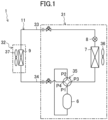
- the compressor (6) is provided in an air conditioner (1) as illustrated in FIG. 1 , for example.
- the air conditioner (1) is a refrigeration apparatus (1) of the present disclosure.
- the air conditioner (1) includes one outdoor unit (31) and one indoor unit (32).
- the outdoor unit (31) and the indoor unit (32) are connected to each other through a liquid communication pipe (33) and a gas communication pipe (34). These components are connected to form a refrigerant circuit (11).
- the refrigerant circuit (11) is filled with refrigerant.
- the refrigerant circuit (11) includes, as main components, the compressor (6), an outdoor heat exchanger (7), an expansion valve (8), an indoor heat exchanger (9), and a four-way switching valve (35).
- the air conditioner (1) performs a refrigeration cycle by circulating refrigerant between the outdoor unit (31) and the indoor unit (32), thereby conditioning air in an indoor space.
- the air conditioner (1) performs cooling operation or heating operation.
- the outdoor unit (31) is placed outside.
- the outdoor unit (31) has the compressor (6), the outdoor heat exchanger (7), the expansion valve (8), the four-way switching valve (35), and an outdoor fan (36).
- the compressor (6) sucks and compresses low-pressure gas refrigerant.
- the compressor (6) discharges the compressed refrigerant. Details of the compressor (6) will be described later.
- the outdoor heat exchanger (7) exchanges heat between outdoor air transported by the outdoor fan (36) and refrigerant.
- the outdoor fan (36) transports outdoor air passing through the outdoor heat exchanger (7).
- the expansion valve (8) decompresses refrigerant.
- the expansion valve (8) is an electric expansion valve having a variable opening degree.
- the expansion valve (8) only has to be connected to the liquid communication pipe (33) of the refrigerant circuit (11), and may be provided in the indoor unit (32).
- the four-way switching valve (35) has a first port (P1), a second port (P2), a third port (P3), and a fourth port (P4).
- the first port (P1) is connected to a discharging portion of the compressor (6).
- the second port (P2) is connected to a suction portion of the compressor (6).
- the third port (P3) is connected to a gas end portion of the outdoor heat exchanger (7).
- the fourth port (P4) is connected to the gas communication pipe (34).
- the four-way switching valve (35) switches between a first state (state indicated by a solid line in FIG. 1 ) and a second state (state indicated by a broken line in FIG. 1 ).
- first state the first port (P1) and the third port (P3) communicate with each other, and the second port (P2) and the fourth port (P4) communicate with each other.
- second state the first port (P1) and the fourth port (P4) communicate with each other, and the second port (P2) and the third port (P3) communicate with each other.
- the indoor unit (32) is placed inside.
- the indoor unit (32) includes an indoor fan (37) and the indoor heat exchanger (9).
- the indoor heat exchanger (9) is a utilization-side heat exchanger of the present disclosure.
- the indoor fan (37) transports indoor air passing through the indoor heat exchanger (9).
- the indoor heat exchanger (9) exchanges heat between indoor air transported by the indoor fan (37) and refrigerant.
- the compressor (6) has the rotary machine unit (10).
- the rotary machine unit (10) includes a casing (20), a stator core (61), and a resin layer (12).
- the compressor (6) includes a compression mechanism (40), a motor (30), and a shaft (50).
- the shaft (50) couples the motor (30) and the compression mechanism (40) to each other.
- the motor (30) includes a stator (60).
- the stator (60) includes the stator core (61).
- the compression mechanism (40) compresses fluid.
- the compression mechanism (40) compresses refrigerant sucked through a suction pipe (21) provided in the casing (20), and discharges the compressed refrigerant into an internal space of the casing (20).
- the refrigerant discharged into the internal space of the casing (20) is discharged through a discharge pipe (22) provided in the casing (20).
- the motor (30) rotationally drives the shaft (50).
- the compression mechanism (40) is driven by rotary drive of the shaft (50).
- the motor (30) includes the stator (60) and a rotor (70).
- an "axial direction” refers to the direction of the axis of the stator (60) (center of rotation of the rotor (70)).
- a “radial direction” refers to a direction perpendicular to the direction of the axis of the stator (60).
- a “circumferential direction” refers to a direction about the axis of the stator (60).
- a “longitudinal section” is a section along the axial direction, and a “transverse section” is a section perpendicular to the axial direction.
- the stator (60) is fixed to the inner peripheral surface of the casing (20).
- the rotor (70) is disposed radially inside the stator (60) with a gap (G) therebetween.
- the motor (30) is an interior permanent magnet synchronous motor.
- the stator (60) has the stator core (61) and coils (65).
- stator core (61) has a back yoke (62) and teeth (63).
- the coil (65) is wound around the tooth (63).
- the coil (65) is wound around the tooth (63) by concentrated winding.
- the rotor (70) has a rotor core (71) and permanent magnets (75). In this example, four permanent magnets (75) are provided.
- the rotor core (71) is provided with slots (72) and a shaft hole (73). In this example, four slots (72) corresponding to the four permanent magnets are provided.
- the rotor core (71) is a laminated core. Specifically, the rotor core (71) is formed by stacking, in the axial direction, a plurality of substantially-circular electromagnetic steel sheets.
- the slot (72) accommodates the permanent magnet (75).
- the four slots (72) are disposed at equal pitches (specifically, 90° pitches) in the circumferential direction.
- the shaft hole (73) penetrates a center portion of the rotor core (71) in the axial direction.
- the shaft (50) is inserted into and fixed to the shaft hole (73).
- the permanent magnet (75) forms the magnetic pole of the rotor (70).
- the four permanent magnets (75) are accommodated in the four slots (72) such that four magnetic poles are formed.
- the permanent magnet (75) is a sintered magnet.
- the casing (20), the stator core (61), and the resin layer (12) forming the rotary machine unit (10) will be described.
- the casing (20) accommodates the components of the rotary machine unit (10).
- the casing (20) has a tubular barrel (20a) extending in the up-down direction and two lids (20b) closing both ends of the barrel.
- a material forming the casing (20) is metal.
- the material forming the casing (20) includes iron.
- the barrel (20a) has a barrel body (23), a large-diameter portion (26), and a groove (25).
- the barrel body (23) is formed in a cylindrical shape.
- the large-diameter portion (26) is formed by expanding the inner diameter of the inner peripheral surface of the barrel (20a).
- the large-diameter portion (26) is substantially the entire inner peripheral surface of the barrel (20a).
- the groove (25) is a concave portion (25) of the present disclosure.
- the groove (25) is a cut groove (25).
- the cut groove (25) is formed in the inner peripheral surface of the barrel (20a).
- the cut groove (25) extends in the up-down direction of the barrel (20a).
- the shape of the inner peripheral surface of the barrel (20a) is a non-perfect circular shape as viewed from the cylinder axis direction of the barrel (20a).
- the shape in the cylinder axis direction of the barrel (20a), is substantially the same in any arbitrary section perpendicular to the cylinder axis direction of the barrel (20a).
- the deviation of the inner peripheral surface of the barrel (20a) from the perfect circle is 0.6% or more.
- G (%) Roundness dmin ( ⁇ m) of Inner Peripheral Surface of Barrel (20a)/Outer Diameter rmin ( ⁇ m) of Barrel (20a)/2 ⁇ 100.
- the roundness of the inner peripheral surface of the barrel (20a) is represented by a difference d between the radius d1 of a circle C1 and the radius d2 of a circle C2 in a case where a distance between these two concentric circles is the minimum when the section perpendicular to the cylinder axis direction of the barrel (20a) is interposed between the two circles C1, C2 with the cylinder axis as the center O, dmin is a value at which the radius difference d is the smallest in an arbitrary section perpendicular to the cylinder axis direction of the barrel, and rmin is the outer diameter of the barrel (20a) in a section in which the radius difference d is dmin.
- the casing (20) accommodates the motor (30), the compression mechanism (40), and the shaft (50).
- the shaft (50) extends in the up-down direction.
- the motor (30) is disposed above the compression mechanism (40).
- the casing (20) is provided with the suction pipe (21) and the discharge pipe (22).
- a suction pipe (21) penetrates the barrel of the casing (20), and is connected to the compression mechanism (40).
- the discharge pipe (22) penetrates an upper portion of the casing (20) to communicate with the internal space of the casing (20).
- the stator core (61) has the back yoke (62) and the teeth (63). In this example, six teeth (63) are provided.
- the stator core (61) is a laminated core. Specifically, the stator core (61) is formed by stacking, in the axial direction, a plurality of substantially-circular electromagnetic steel sheets.
- a material forming the stator core (61) is metal. Specifically, the material forming the stator core (61) includes iron.
- the back yoke (62) is formed in a substantially cylindrical shape.
- the tooth (63) extends radially inward from the inner peripheral surface of the back yoke (62).
- the six teeth (63) are disposed at equal pitches (specifically, 60° pitches) in the circumferential direction.
- the resin layer (12) is a first member (12) of the present disclosure.
- the resin layer (12) has a lower Young's modulus than those of the material forming the casing (20) and the material forming the stator core (61).
- the Young's modulus of the resin layer (12) is 1/10 or less of those of the material forming the casing (20) and that of the material forming the stator core (61).
- the resin layer (12) is made of a resin material.
- the resin material includes thermoplastic resin.
- the thermoplastic resin includes, for example, polyphenylene sulfide (PPS), polybutylene terephthalate (PBT), polyamide (PA) nylon, and liquid crystal polymer (LCP).
- the resin layer (12) is provided between the inner peripheral surface of the barrel (20a) and the outer peripheral surface of the stator core (61). Specifically, the resin layer (12) is provided between the cut groove (25) of the barrel (20a) and the outer peripheral surface of the stator core (61).
- the rotary machine unit (10) of this example is provided in part of a clearance between the inner peripheral surface of the barrel (20a) and the outer peripheral surface of the stator core (61) through the resin layer (12).
- the rotary machine unit (10) of this example has a portion in which the inner peripheral surface of the barrel (20a) and the stator core (61) are fixed to each other through the resin layer (12), and a portion in which the inner peripheral surface of the barrel (20a) and the stator core (61) are fixed in direct contact with each other.
- the rotary machine unit (10) is manufactured by fixing the stator in the barrel (20a) by shrink fit after the barrel (20a) has been formed.
- the barrel (20a) is formed by sequentially forming the barrel body (23), a welded portion (24), the large-diameter portion (26), and the cut groove (25).
- the barrel body (23) is formed by roll-forming into a cylindrical shape after a steel sheet has been cut out into a rectangular shape.
- the welded portion (24) is formed by connecting and welding both ends of the roll-formed barrel body (23) in the circumferential direction. After the metal melted on the inner and outer surfaces of the barrel at the welded portion (24) has been cooled and solidified, a weld bead (27) in which a joint (welded portion (24)) portion is raised in a convex shape is formed.
- the large-diameter portion (26) is formed by uniformly expanding the entire inner peripheral surface of the barrel (20a) radially outward so as to increase the inner diameter of the barrel (20a).
- the cut groove (25) is formed by cutting off part of the weld bead (27) formed on the inner peripheral surface of the barrel (20a).
- a heating step of heating the barrel (20a) is performed (Step ST1).
- the barrel (20a) expands, and the inner diameter of the barrel (20a) expands accordingly.
- the stator core (61) and the resin material are inserted into the barrel (20a) (Step ST2).
- the resin material is disposed such that the resin layer (12) is provided between the cut groove (25) formed in the inner peripheral surface of the barrel (20a) and the outer peripheral surface of the stator core (61).
- Step ST3 a cooling step of cooling the barrel (20a) is performed (Step ST3).
- the barrel (20a) shrinks, and the inner diameter of the barrel (20a) shrinks accordingly.
- the contracted barrel (20a) and the resin material come into contact with each other, and the resin material is melted and deformed by residual heat of the barrel (20a).
- the resin material is cooled and solidified, and fills the cut groove (25) and is deformed by compressive stress from the stator core (61) and the barrel (20a). Accordingly, the resin material comes into close contact with the outer peripheral surface of the stator core (61) and the inner peripheral surface of the barrel (20a). In this manner, the resin layer (12) is formed between the cut groove (25) and the outer peripheral surface of the stator core (61).
- the resin layer (12) (first member) is provided between the inner peripheral surface of the barrel (20a) of the casing (20) formed in the non-perfect circular shape as viewed in the cylinder axis direction and the outer peripheral surface of the stator core (61). Since the resin layer (12) has a lower Young's modulus than those of the material forming the casing (20) and the material forming the stator core (61), the resin layer (12) is relatively easily deformed between the inner peripheral surface of the barrel (20a) and the outer peripheral surface of the stator core (61).
- the resin layer (12) in the clearance between the inner peripheral surface of the barrel (20a) and the outer peripheral surface of the stator core (61) the area of contact between the outer peripheral surface of the stator core (61) and the inner peripheral surface of the barrel (20a) can be increased through the resin layer (12).
- the inner peripheral surface of the barrel (20a) of the casing (20) is formed in the non-perfect circular shape as viewed in the cylinder axis direction, holding force of holding the stator core (61) in the barrel (20a) can be increased, and therefore, the efficiency of the motor for reducing stress on the stator core (61) can be improved.
- the resin layer (12) provided between the stator core (61) and the barrel (20a) can increase the holding force on the stator core (61) in the circumferential direction.
- displacement of the stator core (61) in the circumferential direction in the barrel (20a) can be reduced.
- the barrel (20a) has the concave portion (25) formed in the inner peripheral surface of the barrel (20a), and the resin layer (12) is provided between the concave portion (25) and the outer peripheral surface of the stator core (61).
- the resin layer (12) so as to close the concave portion (25)
- the outer peripheral surface of the stator core (61) and the inner peripheral surface of the barrel (20a) can be fixed to each other through the resin layer (12) at the location where the concave portion (25) is formed.
- the resin layer (12) is formed so as to fill the concave portion (25), it is possible to reduce displacement of the resin layer (12) in the barrel (20a) due to rotation of the motor (30).
- the barrel (20a) has the barrel body (23) and the welded portion (24) connecting both ends of the barrel body (23) in the circumferential direction, and the concave portion (25) is the groove (25) formed in the welded portion (24).
- the resin layer (12) can be provided in the groove (25) formed in the welded portion (24).
- the groove (25) is the cut groove (25) formed in the inner peripheral surface of the barrel (20a).
- the outer peripheral surface of the stator core (61) is prevented from contacting the welded portion (24) as much as possible. This is because the manufacturing tolerance of the welded portion (24) tends to be greater than that of the barrel (20a) other than the welded portion (24).
- stator core (61) and the barrel (20a) are fixed to each other by interference fit in a state in which the outer peripheral surface of the stator core (61) contacts the welded portion (24) of the barrel (20a), the magnitude of stress generated by interference fit varies according to individuals (rotary machine units), or stress is concentrated on specific portions of the stator core (61) and the barrel (20a).
- an individual difference in the quality of the rotary machine unit may increase, breakage such as cracking of the barrel (24a) and the stator core (61) may occur, or the stator core (61) may be dropped.
- the outer peripheral surface of the stator core (61) and the inner peripheral surface of the barrel (20a) can be fixed to each other through the resin layer (12).
- the resin layer (12) in the cut groove (25) the outer peripheral surface of the stator core (61) and the inner peripheral surface of the barrel (20a) can be fixed to each other through the resin layer (12) at the location where the cut groove (25) is formed. This is because formation of the resin layer (12) can reduce variation in stress on the stator core (61) and the barrel (20a) even if the manufacturing tolerance is increased.
- the resin layer (12) can cancel the individual difference in the stress due to the interference fit.
- the barrel (20a) includes the large-diameter portion (26) formed by expanding the inner diameter of the inner peripheral surface of the barrel (20a). Even in the case of the barrel (20a) having such a large-diameter portion (26), the holding force of holding the stator core (61) in the barrel (20a) can be increased by providing the resin layer (12) between the outer peripheral surface of the stator core (61) and the inner peripheral surface of the barrel (20a).
- the resin layer (12) contains the resin material. Since the resin material has a lower Young's modulus than those of the casing (20) and the stator core (61), the resin layer (12) can be formed relatively easily.
- the resin layer (12) contains the thermoplastic resin material
- the stator core (61) is fixed to the inner peripheral surface of the barrel (20a) through the resin layer (12) by shrink fit.
- the thermoplastic resin material is melted and deformed by the heating step for the barrel (20a) by shrink fit.
- the thermoplastic resin is solidified and closely contacts the inner peripheral surface of the barrel (20a) and the outer peripheral surface of the casing (20).
- the resin layer (12) is made of the material having a Young's modulus of 1/10 or less of those of the material forming the casing (20) and the material forming the stator core (61). Such a material is relatively easily deformed between the inner peripheral surface of the barrel (20a) and the outer peripheral surface of the stator core (61), and the resin layer (12) is relatively easily formed from this material.
- the position of the resin layer (12) between the stator core (61) and the barrel (20a) is different from that in the above-described embodiment.
- the rotary machine unit (10) of this variation will be described with reference to FIG. 7 .
- the barrel (20a) of this variation has a weld bead (27) formed on the inner peripheral surface of the barrel (20a).
- the weld bead (27) is a convex portion (27) of the present disclosure.
- the weld bead (27) is a weld mark formed on the surface of the barrel body (23) and the surface of the welded portion (24) connecting both ends of the barrel body (23) in the circumferential direction.
- the weld bead (27) formed on the inner peripheral surface of the barrel (20a) is not cut.
- the barrel (20a) of this variation does not have the cut groove (25).
- the area of contact between the outer peripheral surface of the stator core (61) and the inner peripheral surface of the barrel (20a) can be increased through the resin layer (12).
- the holding force of holding the stator core (61) in the barrel (20a) can also be increased in this variation.
- the weld bead (27) which is generally the joint is prevented from contacting the outer peripheral surface of the stator core (61).
- the resin layer (12) between the weld bead (27) and the outer peripheral surface of the stator core (61) can be fixed to each other through the resin layer (12) at the location where the weld bead (27) is formed on the inner peripheral surface of the barrel (20a). This is because the resin layer (12) can reduce the stress on the cut groove (25).
- the material forming the casing (20) and the material forming the stator core (61) may include an aluminum material.
- the first member (12) may be made of a material having a Young's modulus of 1/2 or less of those of the material forming the casing (20) and the material forming the stator core (61).
- the material forming the casing (20) and the material forming the stator core (61) may contain an iron material
- the material forming the first member (12) may contain an aluminum material.
- the rotary machine unit (10) may have the casing (20), the deviation of the inner peripheral surface of the barrel (20a) of which from the perfect circle is 0.3% or more.
- the rotary machine unit (10) may have the casing (20), the deviation of the inner peripheral surface of the barrel (20a) of which from the perfect circle is 1.0% or more.
- the resin layer (12) may be provided between the inner peripheral surface of the barrel (20a) other than the concave portion (25) formed in or the convex portion (27) formed on the inner peripheral surface of the barrel (20a) and the outer peripheral surface of the stator core (61).
- the resin layer (12) may be provided over the entire circumferences of the inner peripheral surface of the barrel (20a) and the outer peripheral surface of the stator core (61).
- the resin layer (12) may be provided from the upper end to the lower end of the stator core (61), or may be provided partially from the upper end to the lower end of the stator core (61).
- the barrel (20a) may have the groove (25) formed in the inner peripheral surface of the barrel (20a) in the cylinder axis direction and the weld bead (27) formed in the groove (25).
- both ends of the barrel body (23) in the circumferential direction are first formed so as to protrude outward in the radial direction, and then, are welded to form the groove (25), as illustrated in, e.g., FIG. 9A .
- the weld bead (27) is formed in the groove (25) by welding.
- FIG. 9A the weld bead
- the shape of the arbitrary section perpendicular to the cylinder axis direction of the barrel (20a) may vary.
- the convex portion (27) or the concave portion (25) may be formed partially from the upper end to the lower end of the barrel (20a) in the cylinder axis direction.
- the convex portion (27) or the concave portion (25) may be formed in the circumferential direction of the barrel (20a).
- the resin layer (12) is provided between the convex portion (27) on the inner peripheral surface of the barrel (20a) or the concave portion (25) in the inner peripheral surface of the barrel (20a) and the outer peripheral surface of the stator core (61).
- the resin layer (12) provided between the outer peripheral surface of the stator core (61) and the inner peripheral surface of the barrel (20a) may be provided over the entire circumference of the outer peripheral surface of the stator core (61), or may be provided partially. Part of the resin layer (12) may be provided so as to protrude from the upper end or the lower end of the stator core (61).
- the concave portion (25) or the convex portion (27) may be formed in or on the outer peripheral surface of the stator core (61).
- the resin layer (12) is provided between the concave portion (25) in the outer peripheral surface of the stator core (61) or the convex portion (27) on the outer peripheral surface of the stator core (61) and the inner peripheral surface of the barrel (20a).
- the resin layer (12) may contain plural types of resin materials having different properties.
- the resin layer (12) may contain glass fibers or fillers.
- the resin layer (12) may be formed by shrink-fitting the stator core (61) and the barrel (20a) after the resin material has been provided in the cut groove (25).
- the stator core (61) may be fixed in the barrel (20a) by press fit or cold fit.
- the first member (12) may be ceramic.
- the ceramic includes alumina, glass, zirconia, etc.
- the present disclosure is useful for a rotary machine unit, a compressor, and a refrigeration apparatus.
Landscapes
- Engineering & Computer Science (AREA)
- Power Engineering (AREA)
- Mechanical Engineering (AREA)
- General Engineering & Computer Science (AREA)
- Physics & Mathematics (AREA)
- Thermal Sciences (AREA)
- Manufacturing & Machinery (AREA)
- Iron Core Of Rotating Electric Machines (AREA)
- Compressor (AREA)
- Applications Or Details Of Rotary Compressors (AREA)
Abstract
Description
- The present disclosure relates to a rotary machine unit, a compressor, and a refrigeration apparatus.
- Patent Document 1 discloses a compressor configured such that a stator of an electric motor is disposed in a barrel of a casing by clearance fit or transition fit.
- Patent Document 1:
Japanese Unexamined Patent Publication No. 2003-176781 - In the compressor of this type, the shape of the inner peripheral surface of the casing barrel is often a non-perfect circular shape as viewed in a cylinder axis direction. For this reason, a clearance is formed between the outer peripheral surface of a stator core fixed by interference fit and the inner peripheral surface of the barrel of the casing, and holding force of holding the stator core in the barrel may be reduced.
- It is an object of the present disclosure to increase holding force of holding a stator core in a casing having a non-circular barrel.
- A first aspect of the present disclosure is directed to a rotary machine unit including
- a casing (20) having a tubular barrel (20a),
- a stator core (61) fixed to the inner peripheral surface of the barrel (20a), and
- a first member (12) provided between the inner peripheral surface of the barrel (20a) and the outer peripheral surface of the stator core (61),
- the shape of the inner peripheral surface of the barrel (20a) being a non-perfect circular shape as viewed in the cylinder axis direction of the barrel (20a),
- the first member (12) being made of a material having a lower Young's modulus than those of a material forming the barrel (20a) and a material forming the stator core (61).
- In the first aspect, since the first member (12) has a lower Young's modulus than those of the casing (20) and the stator core (61), the first member (12) is relatively easily deformed between the inner peripheral surface of the barrel (20a) and the outer peripheral surface of the stator core (61). Thus, by providing the first member (12) in a clearance between the inner peripheral surface of the barrel (20a) and the outer peripheral surface of the stator core (61), the area of contact between the outer peripheral surface of the stator core (61) and the inner peripheral surface of the barrel (20a) can be increased through the first member (12). As a result, the holding force of holding the stator core (61) in the barrel (20a) can be increased through the first member.
- A second aspect of the present disclosure is an embodiment of the first aspect. In the second aspect,
- the barrel (20a) has a concave portion (25) formed in the inner peripheral surface of the barrel (20a), and
- the first member (12) is provided between the concave portion (25) and the outer peripheral surface of the stator core (61).
- In the second aspect, by providing the first member (12) in the concave portion (25), the outer peripheral surface of the stator core (61) and the inner peripheral surface of the barrel (20a) can be fixed to each other through the first member (12) at the location where the concave portion (25) is formed.
- A third aspect of the present disclosure is an embodiment of the second aspect. In the third aspect,
- the barrel (20a) has a barrel body (23) and a welded portion (24) connecting both ends of the barrel body (23) in a circumferential direction, and
- the concave portion (25) is a groove (25) formed in the welded portion (24).
- In the third aspect, the first member (12) can be provided in the groove (25) which is the concave portion (25).
- A fourth aspect of the present disclosure is an embodiment of the third aspect. In the fourth aspect,
the groove (25) is a cut groove (25) formed in the inner peripheral surface of the barrel (20a). - In the fourth aspect, the first member (12) can be provided in the cut groove (25) which is the groove (25).
- A fifth aspect of the present disclosure is an embodiment of any one of the first to fourth aspects. In the fifth aspect,
- the barrel (20a) has a convex portion (27) formed on the inner peripheral surface of the barrel (20a), and
- the first member (12) is provided between the convex portion (27) and the outer peripheral surface of the stator core (61).
- In the fifth aspect, the first member (12) can be provided in the clearance between the inner peripheral surface of the barrel (20a) and the outer peripheral surface of the stator core (61) at the location where the convex portion (27) is formed. Thus, the outer peripheral surface of the stator core (61) and the inner peripheral surface of the barrel (20a) can also be fixed to each other through the first member (12) at the location where the convex portion (27) is formed.
- A sixth aspect of the present disclosure is an embodiment of the fifth aspect. In the sixth aspect,
- the barrel (20a) has the barrel body (23) and the welded portion (24) connecting both ends of the barrel body (23) in the circumferential direction, and
- the convex portion (27) is a weld bead (27) formed at the welded portion (24).
- In the sixth aspect, the inner peripheral surface of the barrel (20a) and the outer peripheral surface of the stator core (61) can be fixed to each other through the first member (12) at the location where the weld bead (27) is formed.
- A seventh aspect of the present disclosure is an embodiment of any one of the first to sixth aspects. In the seventh aspect,
the barrel (20a) includes a large-diameter portion (26) formed by expanding the inner diameter of the inner peripheral surface of the barrel (20a). - In the seventh aspect, the stator core (61) can be fixed in the barrel (20a) formed with the large-diameter portion (26).
- An eighth aspect of the present disclosure is an embodiment of any one of the first to seventh aspects. In the eighth aspect,
the first member (12) contains a resin material. - In the eighth aspect, the resin material can be used for the first member (12).
- A ninth aspect of the present disclosure is an embodiment of the eighth aspect. In the ninth aspect,
- the first member (12) contains a thermoplastic resin material, and
- the stator core (61) is fixed to the inner peripheral surface of the barrel (20a) through the first member (12) by shrink fit.
- In the ninth aspect, the first member (12) containing the thermoplastic resin material can be deformed by a heating step for the casing (20) by shrink fit. In a subsequent cooling step for the casing (20), the thermoplastic resin material is solidified, and therefore, the first member (12) can closely contact the inner peripheral surface of the barrel (20a) and the outer peripheral surface of the stator core (61).
- A tenth aspect of the present disclosure is an embodiment of any one of the first to ninth aspects. In the tenth aspect,
the first member (12) is made of a material having a Young's modulus of 1/2 or less of those of the material forming the barrel (20a) and the material forming the stator core (61). - In the tenth aspect, the first member (12) can be relatively easily provided between the inner peripheral surface of the barrel (20a) and the outer peripheral surface of the stator core (61).
- An eleventh aspect of the present disclosure is an embodiment of any one of the first to ninth aspects. In the eleventh aspect,
the first member (12) is made of a material having a Young's modulus of 1/10 or less of those of the material forming the barrel (20a) and the material forming the stator core (61). - In the eleventh aspect, the first member (12) can be relatively easily provided between the inner peripheral surface of the barrel (20a) and the outer peripheral surface of the stator core (61).
- A twelfth aspect of the present disclosure is an embodiment of any one of the first to eleventh aspects. In the twelfth aspect,
- the material forming the barrel (20a) and the material forming the stator core (61) contain an iron material, and
- the first member (12) contains an aluminum material.
- In the twelfth aspect, the aluminum material, which is metal having a lower Young's modulus than that of iron, can be used as the first member (12).
- A thirteenth aspect of the present disclosure is an embodiment of any one of the first to eleventh aspects. In the thirteenth aspect,
- the material forming the barrel (20a) and the material forming the stator core (61) are metal, and
- the first member (12) contains resin.
- In the thirteenth aspect, since the resin has a lower Young's modulus than that of metal, the first member (12) can be relatively easily provided between the inner peripheral surface of the barrel (20a) and the outer peripheral surface of the stator core (61).
- A fourteenth aspect of the present disclosure is an embodiment of any one of the first to thirteenth aspects. In the fourteenth aspect,
the deviation of the inner peripheral surface of the barrel (20a) from a perfect circle is 0.3% or more. - In the fourteenth aspect, even if the deviation of the roundness is 0.3% or more, the holding force of holding the stator core (61) in the barrel (20a) can be increased by providing the first member (12).
- A fifteenth aspect of the present disclosure is an embodiment of any one of the first to thirteenth aspects. In the fifteenth aspect,
the deviation of the inner peripheral surface of the barrel (20a) from a perfect circle is 0.6% or more. - In the fifteenth aspect, even if the deviation of the roundness is 0.6% or more, the holding force of holding the stator core (61) in the barrel (20a) can be increased by providing the first member (12).
- A sixteenth aspect of the present disclosure is an embodiment of any one of the first to thirteenth aspects. In the sixteenth aspect,
the deviation of the inner peripheral surface of the barrel (20a) from a perfect circle is 1.0% or more. - In the sixteenth aspect, even if the deviation of the roundness is 1.0% or more, the holding force of holding the stator core (61) in the barrel (20a) can be increased by providing the first member (12).
- A seventeenth aspect of the present disclosure is directed to a compressor including the rotary machine unit of any one of the first to sixteenth aspects.
- An eighteenth aspect of the present disclosure is directed to a refrigeration apparatus including the compressor of the seventeenth aspect.
-
-
FIG. 1 is a schematic diagram showing the configuration of a refrigerant circuit included in a refrigeration apparatus of an embodiment. -
FIG. 2 is a longitudinal sectional view of a compressor having a rotary machine unit of the embodiment. -
FIG. 3 is a sectional view of a barrel in a section perpendicular to a cylinder axis direction for describing deviation from a perfect circle. -
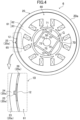
FIG. 4 is a cross-sectional view of the compressor having the rotary machine unit. -
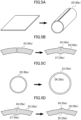
FIG. 5A is a perspective view for describing formation of a barrel body. -
FIG. 5B is an enlarged view of part of the barrel body as viewed in the cylinder axis direction for describing formation of a welded portion. -
FIG. 5C is a view of the barrel body as viewed in the cylinder axis direction for describing formation of a large-diameter portion. -
FIG. 5D is an enlarged view of part of the barrel body for describing formation of a cut groove. -
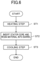
FIG. 6 is a flowchart of a method for fixing a stator to the barrel. -
FIG. 7 is a longitudinal sectional view of a compressor including a rotary machine unit of a first variation. -
FIG. 8 is a longitudinal sectional view of a compressor including a rotary machine unit of another embodiment. -
FIG. 9A is an enlarged view of part of a barrel body as viewed in the cylinder axis direction for describing formation of a barrel of the rotary machine unit ofFIG. 8 . -
FIG. 9B is an enlarged view of part of the barrel body as viewed in the cylinder axis direction for describing formation of the barrel of the rotary machine unit ofFIG. 8 . -
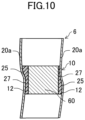
FIG. 10 is a schematic view illustrating the longitudinal section of a compressor having a rotary machine unit of another embodiment. - Embodiments will be described below with reference to the drawings. The following embodiments are merely exemplary ones in nature, and are not intended to limit the scope, application, or use of the present invention. In
FIGS. 4 ,7 , and8 , hatching is partially omitted. - As illustrated in
FIGS. 1 and2 , a rotary machine unit (10) of the embodiment forms a compressor (6) that compresses fluid. The compressor (6) is provided in an air conditioner (1) as illustrated inFIG. 1 , for example. The air conditioner (1) is a refrigeration apparatus (1) of the present disclosure. - The air conditioner (1) includes one outdoor unit (31) and one indoor unit (32). The outdoor unit (31) and the indoor unit (32) are connected to each other through a liquid communication pipe (33) and a gas communication pipe (34). These components are connected to form a refrigerant circuit (11). The refrigerant circuit (11) is filled with refrigerant. The refrigerant circuit (11) includes, as main components, the compressor (6), an outdoor heat exchanger (7), an expansion valve (8), an indoor heat exchanger (9), and a four-way switching valve (35). The air conditioner (1) performs a refrigeration cycle by circulating refrigerant between the outdoor unit (31) and the indoor unit (32), thereby conditioning air in an indoor space. The air conditioner (1) performs cooling operation or heating operation.
- The outdoor unit (31) is placed outside. The outdoor unit (31) has the compressor (6), the outdoor heat exchanger (7), the expansion valve (8), the four-way switching valve (35), and an outdoor fan (36).
- The compressor (6) sucks and compresses low-pressure gas refrigerant. The compressor (6) discharges the compressed refrigerant. Details of the compressor (6) will be described later.
- The outdoor heat exchanger (7) exchanges heat between outdoor air transported by the outdoor fan (36) and refrigerant. The outdoor fan (36) transports outdoor air passing through the outdoor heat exchanger (7).
- The expansion valve (8) decompresses refrigerant. The expansion valve (8) is an electric expansion valve having a variable opening degree. The expansion valve (8) only has to be connected to the liquid communication pipe (33) of the refrigerant circuit (11), and may be provided in the indoor unit (32).
- The four-way switching valve (35) has a first port (P1), a second port (P2), a third port (P3), and a fourth port (P4). The first port (P1) is connected to a discharging portion of the compressor (6). The second port (P2) is connected to a suction portion of the compressor (6). The third port (P3) is connected to a gas end portion of the outdoor heat exchanger (7). The fourth port (P4) is connected to the gas communication pipe (34).
- The four-way switching valve (35) switches between a first state (state indicated by a solid line in
FIG. 1 ) and a second state (state indicated by a broken line inFIG. 1 ). In the first state, the first port (P1) and the third port (P3) communicate with each other, and the second port (P2) and the fourth port (P4) communicate with each other. In the second state, the first port (P1) and the fourth port (P4) communicate with each other, and the second port (P2) and the third port (P3) communicate with each other. By switching the four-way switching valve (35) between the first state and the second state, the air conditioner (1) can switchably operate between the cooling operation and the heating operation. - The indoor unit (32) is placed inside. The indoor unit (32) includes an indoor fan (37) and the indoor heat exchanger (9).
- The indoor heat exchanger (9) is a utilization-side heat exchanger of the present disclosure. The indoor fan (37) transports indoor air passing through the indoor heat exchanger (9). The indoor heat exchanger (9) exchanges heat between indoor air transported by the indoor fan (37) and refrigerant.
- The compressor (6) has the rotary machine unit (10). As will be described in detail later, the rotary machine unit (10) includes a casing (20), a stator core (61), and a resin layer (12). In addition, the compressor (6) includes a compression mechanism (40), a motor (30), and a shaft (50). The shaft (50) couples the motor (30) and the compression mechanism (40) to each other. The motor (30) includes a stator (60). The stator (60) includes the stator core (61).
- The compression mechanism (40) compresses fluid. In this example, the compression mechanism (40) compresses refrigerant sucked through a suction pipe (21) provided in the casing (20), and discharges the compressed refrigerant into an internal space of the casing (20). The refrigerant discharged into the internal space of the casing (20) is discharged through a discharge pipe (22) provided in the casing (20).
- The motor (30) rotationally drives the shaft (50). The compression mechanism (40) is driven by rotary drive of the shaft (50).
- As illustrated in
FIGS. 2 and4 , the motor (30) includes the stator (60) and a rotor (70). - In the following description, an "axial direction" refers to the direction of the axis of the stator (60) (center of rotation of the rotor (70)). A "radial direction" refers to a direction perpendicular to the direction of the axis of the stator (60). A "circumferential direction" refers to a direction about the axis of the stator (60). A "longitudinal section" is a section along the axial direction, and a "transverse section" is a section perpendicular to the axial direction.
- The stator (60) is fixed to the inner peripheral surface of the casing (20). The rotor (70) is disposed radially inside the stator (60) with a gap (G) therebetween. In this example, the motor (30) is an interior permanent magnet synchronous motor.
- The stator (60) has the stator core (61) and coils (65).
- Although will be described in detail later, the stator core (61) has a back yoke (62) and teeth (63).
- The coil (65) is wound around the tooth (63). In this example, the coil (65) is wound around the tooth (63) by concentrated winding.
- The rotor (70) has a rotor core (71) and permanent magnets (75). In this example, four permanent magnets (75) are provided.
- The rotor core (71) is provided with slots (72) and a shaft hole (73). In this example, four slots (72) corresponding to the four permanent magnets are provided. The rotor core (71) is a laminated core. Specifically, the rotor core (71) is formed by stacking, in the axial direction, a plurality of substantially-circular electromagnetic steel sheets.
- The slot (72) accommodates the permanent magnet (75). In this example, the four slots (72) are disposed at equal pitches (specifically, 90° pitches) in the circumferential direction.
- The shaft hole (73) penetrates a center portion of the rotor core (71) in the axial direction. The shaft (50) is inserted into and fixed to the shaft hole (73).
- The permanent magnet (75) forms the magnetic pole of the rotor (70). In this example, the four permanent magnets (75) are accommodated in the four slots (72) such that four magnetic poles are formed. The permanent magnet (75) is a sintered magnet.
- The casing (20), the stator core (61), and the resin layer (12) forming the rotary machine unit (10) will be described.
- The casing (20) accommodates the components of the rotary machine unit (10). The casing (20) has a tubular barrel (20a) extending in the up-down direction and two lids (20b) closing both ends of the barrel. A material forming the casing (20) is metal. Specifically, the material forming the casing (20) includes iron.
- The barrel (20a) has a barrel body (23), a large-diameter portion (26), and a groove (25). The barrel body (23) is formed in a cylindrical shape. The large-diameter portion (26) is formed by expanding the inner diameter of the inner peripheral surface of the barrel (20a). The large-diameter portion (26) is substantially the entire inner peripheral surface of the barrel (20a). The groove (25) is a concave portion (25) of the present disclosure. Specifically, the groove (25) is a cut groove (25). As will be described in detail later, the cut groove (25) is formed in the inner peripheral surface of the barrel (20a). The cut groove (25) extends in the up-down direction of the barrel (20a).
- In a section perpendicular to the cylinder axis direction of the barrel (20a), the shape of the inner peripheral surface of the barrel (20a) is a non-perfect circular shape as viewed from the cylinder axis direction of the barrel (20a). In this example, in the cylinder axis direction of the barrel (20a), the shape is substantially the same in any arbitrary section perpendicular to the cylinder axis direction of the barrel (20a). Specifically, the deviation of the inner peripheral surface of the barrel (20a) from the perfect circle is 0.6% or more. The "deviation from the perfect circle" G is obtained by G (%) = Roundness dmin (µm) of Inner Peripheral Surface of Barrel (20a)/Outer Diameter rmin (µm) of Barrel (20a)/2 × 100.
- As illustrated in
FIG. 3 , the roundness of the inner peripheral surface of the barrel (20a) is represented by a difference d between the radius d1 of a circle C1 and the radius d2 of a circle C2 in a case where a distance between these two concentric circles is the minimum when the section perpendicular to the cylinder axis direction of the barrel (20a) is interposed between the two circles C1, C2 with the cylinder axis as the center O, dmin is a value at which the radius difference d is the smallest in an arbitrary section perpendicular to the cylinder axis direction of the barrel, and rmin is the outer diameter of the barrel (20a) in a section in which the radius difference d is dmin. - As illustrated in
FIG. 2 , the casing (20) accommodates the motor (30), the compression mechanism (40), and the shaft (50). The shaft (50) extends in the up-down direction. The motor (30) is disposed above the compression mechanism (40). - The casing (20) is provided with the suction pipe (21) and the discharge pipe (22). A suction pipe (21) penetrates the barrel of the casing (20), and is connected to the compression mechanism (40). The discharge pipe (22) penetrates an upper portion of the casing (20) to communicate with the internal space of the casing (20).
- The stator core (61) has the back yoke (62) and the teeth (63). In this example, six teeth (63) are provided. The stator core (61) is a laminated core. Specifically, the stator core (61) is formed by stacking, in the axial direction, a plurality of substantially-circular electromagnetic steel sheets. A material forming the stator core (61) is metal. Specifically, the material forming the stator core (61) includes iron.
- The back yoke (62) is formed in a substantially cylindrical shape.
- The tooth (63) extends radially inward from the inner peripheral surface of the back yoke (62). In this example, the six teeth (63) are disposed at equal pitches (specifically, 60° pitches) in the circumferential direction.
- The resin layer (12) is a first member (12) of the present disclosure. The resin layer (12) has a lower Young's modulus than those of the material forming the casing (20) and the material forming the stator core (61). The Young's modulus of the resin layer (12) is 1/10 or less of those of the material forming the casing (20) and that of the material forming the stator core (61). Specifically, the resin layer (12) is made of a resin material. The resin material includes thermoplastic resin. The thermoplastic resin includes, for example, polyphenylene sulfide (PPS), polybutylene terephthalate (PBT), polyamide (PA) nylon, and liquid crystal polymer (LCP).
- The resin layer (12) is provided between the inner peripheral surface of the barrel (20a) and the outer peripheral surface of the stator core (61). Specifically, the resin layer (12) is provided between the cut groove (25) of the barrel (20a) and the outer peripheral surface of the stator core (61).
- As described above, the rotary machine unit (10) of this example is provided in part of a clearance between the inner peripheral surface of the barrel (20a) and the outer peripheral surface of the stator core (61) through the resin layer (12). The rotary machine unit (10) of this example has a portion in which the inner peripheral surface of the barrel (20a) and the stator core (61) are fixed to each other through the resin layer (12), and a portion in which the inner peripheral surface of the barrel (20a) and the stator core (61) are fixed in direct contact with each other.
- Next, a method for manufacturing the rotary machine unit (10) will be described. The rotary machine unit (10) is manufactured by fixing the stator in the barrel (20a) by shrink fit after the barrel (20a) has been formed.
- As illustrated in
FIGS. 5A to 5D , the barrel (20a) is formed by sequentially forming the barrel body (23), a welded portion (24), the large-diameter portion (26), and the cut groove (25). - As illustrated in
FIG. 5A , the barrel body (23) is formed by roll-forming into a cylindrical shape after a steel sheet has been cut out into a rectangular shape. - As illustrated in
FIG. 5B , the welded portion (24) is formed by connecting and welding both ends of the roll-formed barrel body (23) in the circumferential direction. After the metal melted on the inner and outer surfaces of the barrel at the welded portion (24) has been cooled and solidified, a weld bead (27) in which a joint (welded portion (24)) portion is raised in a convex shape is formed. - As illustrated in
FIG. 5C , the large-diameter portion (26) is formed by uniformly expanding the entire inner peripheral surface of the barrel (20a) radially outward so as to increase the inner diameter of the barrel (20a). - As illustrated in
FIG. 5D , the cut groove (25) is formed by cutting off part of the weld bead (27) formed on the inner peripheral surface of the barrel (20a). - Next, a method of fixing the stator core (61) in the barrel (20a) by shrink fit will be described.
- As illustrated in
FIG. 6 , a heating step of heating the barrel (20a) is performed (Step ST1). By heating, the barrel (20a) expands, and the inner diameter of the barrel (20a) expands accordingly. Next, the stator core (61) and the resin material are inserted into the barrel (20a) (Step ST2). At this time, the resin material is disposed such that the resin layer (12) is provided between the cut groove (25) formed in the inner peripheral surface of the barrel (20a) and the outer peripheral surface of the stator core (61). - Thereafter, a cooling step of cooling the barrel (20a) is performed (Step ST3). By the cooling step, the barrel (20a) shrinks, and the inner diameter of the barrel (20a) shrinks accordingly. The contracted barrel (20a) and the resin material come into contact with each other, and the resin material is melted and deformed by residual heat of the barrel (20a). By further cooling, the resin material is cooled and solidified, and fills the cut groove (25) and is deformed by compressive stress from the stator core (61) and the barrel (20a). Accordingly, the resin material comes into close contact with the outer peripheral surface of the stator core (61) and the inner peripheral surface of the barrel (20a). In this manner, the resin layer (12) is formed between the cut groove (25) and the outer peripheral surface of the stator core (61).
- In the rotary machine unit (10) of the embodiment, the resin layer (12) (first member) is provided between the inner peripheral surface of the barrel (20a) of the casing (20) formed in the non-perfect circular shape as viewed in the cylinder axis direction and the outer peripheral surface of the stator core (61). Since the resin layer (12) has a lower Young's modulus than those of the material forming the casing (20) and the material forming the stator core (61), the resin layer (12) is relatively easily deformed between the inner peripheral surface of the barrel (20a) and the outer peripheral surface of the stator core (61). Thus, by providing the resin layer (12) in the clearance between the inner peripheral surface of the barrel (20a) and the outer peripheral surface of the stator core (61), the area of contact between the outer peripheral surface of the stator core (61) and the inner peripheral surface of the barrel (20a) can be increased through the resin layer (12). As a result, even if the inner peripheral surface of the barrel (20a) of the casing (20) is formed in the non-perfect circular shape as viewed in the cylinder axis direction, holding force of holding the stator core (61) in the barrel (20a) can be increased, and therefore, the efficiency of the motor for reducing stress on the stator core (61) can be improved.
- In addition, the resin layer (12) provided between the stator core (61) and the barrel (20a) can increase the holding force on the stator core (61) in the circumferential direction. Thus, even when the rotor (70) rotates, displacement of the stator core (61) in the circumferential direction in the barrel (20a) can be reduced.
- In the rotary machine unit (10) of the embodiment, the barrel (20a) has the concave portion (25) formed in the inner peripheral surface of the barrel (20a), and the resin layer (12) is provided between the concave portion (25) and the outer peripheral surface of the stator core (61). By providing the resin layer (12) so as to close the concave portion (25), the outer peripheral surface of the stator core (61) and the inner peripheral surface of the barrel (20a) can be fixed to each other through the resin layer (12) at the location where the concave portion (25) is formed. In addition, since the resin layer (12) is formed so as to fill the concave portion (25), it is possible to reduce displacement of the resin layer (12) in the barrel (20a) due to rotation of the motor (30).
- In the rotary machine unit (10) of the embodiment, the barrel (20a) has the barrel body (23) and the welded portion (24) connecting both ends of the barrel body (23) in the circumferential direction, and the concave portion (25) is the groove (25) formed in the welded portion (24). Thus, the resin layer (12) can be provided in the groove (25) formed in the welded portion (24).
- In the rotary machine unit (10) of the embodiment, the groove (25) is the cut groove (25) formed in the inner peripheral surface of the barrel (20a). In general, in a case where the stator core (61) and the barrel (20a) are fixed to each other by interference fit, the outer peripheral surface of the stator core (61) is prevented from contacting the welded portion (24) as much as possible. This is because the manufacturing tolerance of the welded portion (24) tends to be greater than that of the barrel (20a) other than the welded portion (24). For this reason, if the stator core (61) and the barrel (20a) are fixed to each other by interference fit in a state in which the outer peripheral surface of the stator core (61) contacts the welded portion (24) of the barrel (20a), the magnitude of stress generated by interference fit varies according to individuals (rotary machine units), or stress is concentrated on specific portions of the stator core (61) and the barrel (20a). As a result, an individual difference in the quality of the rotary machine unit may increase, breakage such as cracking of the barrel (24a) and the stator core (61) may occur, or the stator core (61) may be dropped.
- On the other hand, in the rotary machine unit (10) of this example, the outer peripheral surface of the stator core (61) and the inner peripheral surface of the barrel (20a) can be fixed to each other through the resin layer (12). By providing the resin layer (12) in the cut groove (25), the outer peripheral surface of the stator core (61) and the inner peripheral surface of the barrel (20a) can be fixed to each other through the resin layer (12) at the location where the cut groove (25) is formed. This is because formation of the resin layer (12) can reduce variation in stress on the stator core (61) and the barrel (20a) even if the manufacturing tolerance is increased. In addition, the resin layer (12) can cancel the individual difference in the stress due to the interference fit.
- In the rotary machine unit (10) of the embodiment, the barrel (20a) includes the large-diameter portion (26) formed by expanding the inner diameter of the inner peripheral surface of the barrel (20a). Even in the case of the barrel (20a) having such a large-diameter portion (26), the holding force of holding the stator core (61) in the barrel (20a) can be increased by providing the resin layer (12) between the outer peripheral surface of the stator core (61) and the inner peripheral surface of the barrel (20a).
- In the rotary machine unit (10) of the embodiment, the resin layer (12) contains the resin material. Since the resin material has a lower Young's modulus than those of the casing (20) and the stator core (61), the resin layer (12) can be formed relatively easily.
- In the rotary machine unit (10) of the embodiment, the resin layer (12) contains the thermoplastic resin material, and the stator core (61) is fixed to the inner peripheral surface of the barrel (20a) through the resin layer (12) by shrink fit. The thermoplastic resin material is melted and deformed by the heating step for the barrel (20a) by shrink fit. In the subsequent cooling step for the barrel (20a), the thermoplastic resin is solidified and closely contacts the inner peripheral surface of the barrel (20a) and the outer peripheral surface of the casing (20). By forming such a resin layer (12), the holding force of holding the stator core (61) in the barrel (20a) can be increased.
- In the rotary machine unit (10) of the embodiment, the resin layer (12) is made of the material having a Young's modulus of 1/10 or less of those of the material forming the casing (20) and the material forming the stator core (61). Such a material is relatively easily deformed between the inner peripheral surface of the barrel (20a) and the outer peripheral surface of the stator core (61), and the resin layer (12) is relatively easily formed from this material.
- In the rotary machine unit (10) of this example, the position of the resin layer (12) between the stator core (61) and the barrel (20a) is different from that in the above-described embodiment. Hereinafter, the rotary machine unit (10) of this variation will be described with reference to
FIG. 7 . - The barrel (20a) of this variation has a weld bead (27) formed on the inner peripheral surface of the barrel (20a). The weld bead (27) is a convex portion (27) of the present disclosure. The weld bead (27) is a weld mark formed on the surface of the barrel body (23) and the surface of the welded portion (24) connecting both ends of the barrel body (23) in the circumferential direction.
- In the step of forming the barrel (20a) in this variation, the weld bead (27) formed on the inner peripheral surface of the barrel (20a) is not cut. In other words, the barrel (20a) of this variation does not have the cut groove (25).
- By providing the resin layer (12) between the weld bead (27) on the inner peripheral surface of the barrel (20a) and the outer peripheral surface of the stator core (61), the area of contact between the outer peripheral surface of the stator core (61) and the inner peripheral surface of the barrel (20a) can be increased through the resin layer (12). Thus, even if the inner peripheral surface of the barrel (20a) is formed in the non-perfect circular shape as viewed in the cylinder axis direction, the holding force of holding the stator core (61) in the barrel (20a) can also be increased in this variation.
- In addition, as described above, when the stator core (61) and the barrel (20a) are fixed to each other by interference fit, the weld bead (27) which is generally the joint is prevented from contacting the outer peripheral surface of the stator core (61). However, by providing the resin layer (12) between the weld bead (27) and the outer peripheral surface of the stator core (61), the outer peripheral surface of the stator core (61) and the inner peripheral surface of the barrel (20a) can be fixed to each other through the resin layer (12) at the location where the weld bead (27) is formed on the inner peripheral surface of the barrel (20a). This is because the resin layer (12) can reduce the stress on the cut groove (25).
- In addition, even when the motor (30) rotates, the resin layer (12) is caught by the weld bead (27), and therefore, displacement of the resin layer (12) in the barrel (20a) can be reduced.
- The above-described embodiment and variation may be modified in the following manner.
- In the embodiment, in the rotary machine unit (10), the material forming the casing (20) and the material forming the stator core (61) may include an aluminum material.
- The first member (12) may be made of a material having a Young's modulus of 1/2 or less of those of the material forming the casing (20) and the material forming the stator core (61). For example, the material forming the casing (20) and the material forming the stator core (61) may contain an iron material, and the material forming the first member (12) may contain an aluminum material.
- The rotary machine unit (10) may have the casing (20), the deviation of the inner peripheral surface of the barrel (20a) of which from the perfect circle is 0.3% or more.
- The rotary machine unit (10) may have the casing (20), the deviation of the inner peripheral surface of the barrel (20a) of which from the perfect circle is 1.0% or more.
- The resin layer (12) may be provided between the inner peripheral surface of the barrel (20a) other than the concave portion (25) formed in or the convex portion (27) formed on the inner peripheral surface of the barrel (20a) and the outer peripheral surface of the stator core (61).
- The resin layer (12) may be provided over the entire circumferences of the inner peripheral surface of the barrel (20a) and the outer peripheral surface of the stator core (61).
- The resin layer (12) may be provided from the upper end to the lower end of the stator core (61), or may be provided partially from the upper end to the lower end of the stator core (61).
- As illustrated in
FIG. 8 , the barrel (20a) may have the groove (25) formed in the inner peripheral surface of the barrel (20a) in the cylinder axis direction and the weld bead (27) formed in the groove (25). As a method of forming such a barrel (20a), both ends of the barrel body (23) in the circumferential direction are first formed so as to protrude outward in the radial direction, and then, are welded to form the groove (25), as illustrated in, e.g.,FIG. 9A . At this time, the weld bead (27) is formed in the groove (25) by welding. Alternatively, as illustrated inFIG. 9B , after both ends of the barrel body (23) in the circumferential direction have been cut out, the groove (25) is formed in the inner peripheral surface of the barrel (20a) upon welding. At this time, the weld bead (27) is formed in the groove (25) by welding. - The shape of the arbitrary section perpendicular to the cylinder axis direction of the barrel (20a) may vary. Specifically, the convex portion (27) or the concave portion (25) may be formed partially from the upper end to the lower end of the barrel (20a) in the cylinder axis direction.
- In addition, as illustrated in
FIG. 10 , the convex portion (27) or the concave portion (25) may be formed in the circumferential direction of the barrel (20a). Also in this case, the resin layer (12) is provided between the convex portion (27) on the inner peripheral surface of the barrel (20a) or the concave portion (25) in the inner peripheral surface of the barrel (20a) and the outer peripheral surface of the stator core (61). The resin layer (12) provided between the outer peripheral surface of the stator core (61) and the inner peripheral surface of the barrel (20a) may be provided over the entire circumference of the outer peripheral surface of the stator core (61), or may be provided partially. Part of the resin layer (12) may be provided so as to protrude from the upper end or the lower end of the stator core (61). - The concave portion (25) or the convex portion (27) may be formed in or on the outer peripheral surface of the stator core (61). In this case, the resin layer (12) is provided between the concave portion (25) in the outer peripheral surface of the stator core (61) or the convex portion (27) on the outer peripheral surface of the stator core (61) and the inner peripheral surface of the barrel (20a).
- The resin layer (12) may contain plural types of resin materials having different properties. The resin layer (12) may contain glass fibers or fillers.
- The resin layer (12) may be formed by shrink-fitting the stator core (61) and the barrel (20a) after the resin material has been provided in the cut groove (25).
- The stator core (61) may be fixed in the barrel (20a) by press fit or cold fit.
- The first member (12) may be ceramic. The ceramic includes alumina, glass, zirconia, etc.
- While the embodiments and variations thereof have been described above, it will be understood that various changes in form and details may be made without departing from the spirit and scope of the claims. The foregoing embodiments and variations thereof may be combined and replaced with each other without deteriorating the intended functions of the present disclosure. The expressions of "first," "second," ... described above are used to distinguish the terms to which these expressions are given, and do not limit the number and order of the terms.
- As described above, the present disclosure is useful for a rotary machine unit, a compressor, and a refrigeration apparatus.
-
- 1
- Refrigeration Apparatus
- 6
- Compressor
- 10
- Rotary Machine Unit
- 12
- First Member
- 20
- Casing
- 20a
- Barrel
- 23
- Barrel Body
- 24
- Weld Portion
- 25
- Concave Portion
- 26
- Large-Diameter Portion
- 27
- Convex Portion
- 27
- Weld Bead
- 61
- Stator Core
Claims (18)
- A rotary machine unit, comprising:a casing (20) having a tubular barrel (20a);a stator core (61) fixed to an inner peripheral surface of the barrel (20a); anda first member (12) provided between the inner peripheral surface of the barrel (20a) and an outer peripheral surface of the stator core (61),a shape of the inner peripheral surface of the barrel (20a) being a non-perfect circular shape as viewed in a cylinder axis direction of the barrel (20a),the first member (12) being made of a material having a lower Young's modulus than those of a material forming the barrel (20a) and a material forming the stator core (61).
- The rotary machine unit of claim 1, whereinthe barrel (20a) has a concave portion (25) formed in the inner peripheral surface of the barrel (20a), andthe first member (12) is provided between the concave portion (25) and the outer peripheral surface of the stator core (61).
- The rotary machine unit of claim 2, whereinthe barrel (20a) has a barrel body (23) and a welded portion (24) connecting both ends of the barrel body (23) in a circumferential direction, andthe concave portion (25) is a groove (25) formed in the welded portion (24).
- The rotary machine unit of claim 3, wherein
the groove (25) is a cut groove (25) formed in the inner peripheral surface of the barrel (20a). - The rotary machine unit of any one of claims 1 to 4, whereinthe barrel (20a) has a convex portion (27) formed on the inner peripheral surface of the barrel (20a), andthe first member (12) is provided between the convex portion (27) and the outer peripheral surface of the stator core (61).
- The rotary machine unit of claim 5, whereinthe barrel (20a) has the barrel body (23) and the welded portion (24) connecting the both ends of the barrel body (23) in the circumferential direction, andthe convex portion (27) is a weld bead (27) formed at the welded portion (24).
- The rotary machine unit of any one of claims 1 to 6, wherein
the barrel (20a) includes a large-diameter portion (26) formed by expanding an inner diameter of the inner peripheral surface of the barrel (20a). - The rotary machine unit of any one of claims 1 to 7, wherein
the first member (12) contains a resin material. - The rotary machine unit of claim 8, whereinthe first member (12) contains a thermoplastic resin material, andthe stator core (61) is fixed to the inner peripheral surface of the barrel (20a) through the first member (12) by shrink fit.
- The rotary machine unit of any one of claims 1 to 9, wherein
the first member (12) is made of a material having a Young's modulus of 1/2 or less of those of the material forming the barrel (20a) and the material forming the stator core (61). - The rotary machine unit of any one of claims 1 to 9, wherein
the first member (12) is made of a material having a Young's modulus of 1/10 or less of those of the material forming the barrel (20a) and the material forming the stator core (61). - The rotary machine unit of any one of claims 1 to 11, whereinthe material forming the barrel (20a) and the material forming the stator core (61) contain an iron material, andthe first member (12) contains an aluminum material.
- The rotary machine unit of any one of claims 1 to 11, whereinthe material forming the barrel (20a) and the material forming the stator core (61) are metal, andthe first member (12) contains resin.
- The rotary machine unit of any one of claims 1 to 13, wherein
a deviation of the inner peripheral surface of the barrel (20a) from a perfect circle is 0.3% or more. - The rotary machine unit of any one of claims 1 to 13, wherein
a deviation of the inner peripheral surface of the barrel (20a) from a perfect circle is 0.6% or more. - The rotary machine unit of any one of claims 1 to 13, wherein
a deviation of the inner peripheral surface of the barrel (20a) from a perfect circle is 1.0% or more. - A compressor comprising:
the rotary machine unit (10) of any one of claims 1 to 16. - A refrigeration apparatus comprising:
the compressor (6) of claim 17.
Applications Claiming Priority (2)
| Application Number | Priority Date | Filing Date | Title |
|---|---|---|---|
| JP2021053059A JP7168883B2 (en) | 2021-03-26 | 2021-03-26 | Rotating Machinery Units, Compressors, and Refrigeration Equipment |
| PCT/JP2022/012195 WO2022202595A1 (en) | 2021-03-26 | 2022-03-17 | Rotary machine unit, compressor, and refrigeration device |
Publications (3)
| Publication Number | Publication Date |
|---|---|
| EP4293225A1 true EP4293225A1 (en) | 2023-12-20 |
| EP4293225A4 EP4293225A4 (en) | 2024-08-14 |
| EP4293225B1 EP4293225B1 (en) | 2025-08-13 |
Family
ID=83395739
Family Applications (1)
| Application Number | Title | Priority Date | Filing Date |
|---|---|---|---|
| EP22775383.7A Active EP4293225B1 (en) | 2021-03-26 | 2022-03-17 | Rotary machine unit, compressor, and refrigeration device |
Country Status (5)
| Country | Link |
|---|---|
| US (1) | US12646982B2 (en) |
| EP (1) | EP4293225B1 (en) |
| JP (1) | JP7168883B2 (en) |
| CN (1) | CN117098915A (en) |
| WO (1) | WO2022202595A1 (en) |
Families Citing this family (3)
| Publication number | Priority date | Publication date | Assignee | Title |
|---|---|---|---|---|
| JP7148828B1 (en) * | 2021-08-17 | 2022-10-06 | ダイキン工業株式会社 | Compressor manufacturing method |
| WO2024218928A1 (en) * | 2023-04-20 | 2024-10-24 | 三菱電機株式会社 | Compressor and refrigeration cycle device |
| JP7708293B1 (en) * | 2024-11-18 | 2025-07-15 | 株式会社富士通ゼネラル | Compressor |
Family Cites Families (16)
| Publication number | Priority date | Publication date | Assignee | Title |
|---|---|---|---|---|
| DE1037572B (en) * | 1955-10-21 | 1958-08-28 | Licentia Gmbh | Electric machine in which the sheet metal stacks are united with the parts that carry them with an adhesive |
| JPH0283393U (en) * | 1988-12-16 | 1990-06-27 | ||
| JP4592143B2 (en) * | 2000-04-06 | 2010-12-01 | パナソニック株式会社 | Compressor and electric motor |
| JP4487382B2 (en) * | 2000-04-27 | 2010-06-23 | 三菱電機株式会社 | Hermetic compressor, manufacturing method thereof, refrigeration / air-conditioning apparatus. |
| JP3963211B2 (en) | 2001-12-07 | 2007-08-22 | 三菱電機株式会社 | Hermetic compressor |
| JP2006027355A (en) * | 2004-07-13 | 2006-02-02 | Nsk Ltd | Electric power steering device |
| JP4241849B2 (en) * | 2007-04-02 | 2009-03-18 | ダイキン工業株式会社 | Compressor |
| JP2008267241A (en) * | 2007-04-19 | 2008-11-06 | Matsushita Electric Ind Co Ltd | Hermetic electric compressor |
| JP2009068468A (en) * | 2007-09-18 | 2009-04-02 | Panasonic Corp | Manufacturing method of hermetic electric compressor |
| JP2009095184A (en) | 2007-10-11 | 2009-04-30 | Asmo Co Ltd | Dynamo-electric machine |
| JP2011055576A (en) | 2009-08-31 | 2011-03-17 | Daikin Industries Ltd | Compressor |
| JP6131463B2 (en) | 2013-01-09 | 2017-05-24 | パナソニックIpマネジメント株式会社 | Stator fixing method of motor part in hermetic compressor |
| JP6233726B2 (en) * | 2013-10-15 | 2017-11-22 | パナソニックIpマネジメント株式会社 | Compressor |
| WO2017141361A1 (en) | 2016-02-16 | 2017-08-24 | 株式会社安川電機 | Rotary electric machine and method for manufacturing rotary electric machine |
| JP2018133948A (en) * | 2017-02-16 | 2018-08-23 | 日本電産株式会社 | motor |
| JP6901035B2 (en) * | 2019-09-30 | 2021-07-14 | ダイキン工業株式会社 | Manufacturing methods for rotating electric machines, compressors, and rotating electric machines |
-
2021
- 2021-03-26 JP JP2021053059A patent/JP7168883B2/en active Active
-
2022
- 2022-03-17 EP EP22775383.7A patent/EP4293225B1/en active Active
- 2022-03-17 CN CN202280023251.4A patent/CN117098915A/en active Pending
- 2022-03-17 WO PCT/JP2022/012195 patent/WO2022202595A1/en not_active Ceased
-
2023
- 2023-09-21 US US18/371,219 patent/US12646982B2/en active Active
Also Published As
| Publication number | Publication date |
|---|---|
| US12646982B2 (en) | 2026-06-02 |
| EP4293225B1 (en) | 2025-08-13 |
| EP4293225A4 (en) | 2024-08-14 |
| WO2022202595A1 (en) | 2022-09-29 |
| JP7168883B2 (en) | 2022-11-10 |
| CN117098915A (en) | 2023-11-21 |
| US20240014698A1 (en) | 2024-01-11 |
| JP2022150453A (en) | 2022-10-07 |
Similar Documents
| Publication | Publication Date | Title |
|---|---|---|
| EP4293225B1 (en) | Rotary machine unit, compressor, and refrigeration device | |
| CN108028557B (en) | Permanent magnet embedded motors, compressors and refrigeration and air-conditioning units | |
| JP6656428B2 (en) | Stator, electric motor, compressor, and refrigeration air conditioner | |
| EP2144347A1 (en) | Rotating electric machine and compressor | |
| US10797540B2 (en) | Stator, motor, compressor, and refrigeration air conditioner | |
| EP2113987A1 (en) | Insulator for motor, stator, motor and compressor | |
| JP2023168510A (en) | Motor, compressor, air blower, and refrigerating air conditioner | |
| JP3960122B2 (en) | Electric compressor | |
| US20090108696A1 (en) | Interphase insulating sheet of rotating electric machine, and electric compressor | |
| CN109309413B (en) | Rotor, rotating electric machine, and method for manufacturing rotor | |
| US20160315517A1 (en) | Compressor | |
| WO2018029818A1 (en) | Electric motor, compressor, refrigeration and air conditioning device, and method for manufacturing electric motor | |
| US20120301334A1 (en) | Compressor and Refrigerating Cycle Apparatus | |
| WO2019102574A1 (en) | Electric motor, compressor, and refrigeration cycle device | |
| WO2019073509A1 (en) | Stator, electric motor, compressor, air conditioning device, and stator manufacturing method | |
| EP2199615B1 (en) | Motor for compressor, compressor, and refrigerating cycle apparatus | |
| JP6918240B2 (en) | Motors, compressors, blowers, and refrigerating air conditioners | |
| JP2010252511A (en) | Motor, compressor and air conditioner | |
| JP7130051B2 (en) | Rotors, electric motors, compressors, and refrigeration and air conditioning equipment | |
| EP3876396B1 (en) | Stator, electric motor, compressor, air conditioner, and stator manufacturing method | |
| JP7026805B2 (en) | Manufacturing method of stator, motor, fan, air conditioner and stator | |
| CN112204853A (en) | Stator, motor, compressor, and air conditioner | |
| JP2004293446A (en) | Hermetic compressor | |
| CN110366809B (en) | Rotating electric machines, compressors, and refrigeration cycle devices | |
| JP6632722B2 (en) | Stator, electric motor, compressor, vacuum cleaner and stator manufacturing method |
Legal Events
| Date | Code | Title | Description |
|---|---|---|---|
| STAA | Information on the status of an ep patent application or granted ep patent |
Free format text: STATUS: THE INTERNATIONAL PUBLICATION HAS BEEN MADE |
|
| PUAI | Public reference made under article 153(3) epc to a published international application that has entered the european phase |
Free format text: ORIGINAL CODE: 0009012 |
|
| STAA | Information on the status of an ep patent application or granted ep patent |
Free format text: STATUS: REQUEST FOR EXAMINATION WAS MADE |
|
| 17P | Request for examination filed |
Effective date: 20230914 |
|
| AK | Designated contracting states |
Kind code of ref document: A1 Designated state(s): AL AT BE BG CH CY CZ DE DK EE ES FI FR GB GR HR HU IE IS IT LI LT LU LV MC MK MT NL NO PL PT RO RS SE SI SK SM TR |
|
| DAV | Request for validation of the european patent (deleted) | ||
| DAX | Request for extension of the european patent (deleted) | ||
| REG | Reference to a national code |
Ref country code: DE Ref legal event code: R079 Free format text: PREVIOUS MAIN CLASS: F04B0039000000 Ipc: H02K0001180000 Ref country code: DE Ref legal event code: R079 Ref document number: 602022019487 Country of ref document: DE Free format text: PREVIOUS MAIN CLASS: F04B0039000000 Ipc: H02K0001180000 |
|
| P01 | Opt-out of the competence of the unified patent court (upc) registered |
Free format text: CASE NUMBER: APP_38319/2024 Effective date: 20240627 |
|
| A4 | Supplementary search report drawn up and despatched |
Effective date: 20240711 |
|
| RIC1 | Information provided on ipc code assigned before grant |
Ipc: F04C 23/00 20060101ALI20240705BHEP Ipc: F04C 18/356 20060101ALI20240705BHEP Ipc: F04B 35/04 20060101ALI20240705BHEP Ipc: F04C 29/00 20060101ALI20240705BHEP Ipc: F04B 39/00 20060101ALI20240705BHEP Ipc: H02K 5/24 20060101ALI20240705BHEP Ipc: H02K 15/14 20060101ALI20240705BHEP Ipc: H02K 1/18 20060101AFI20240705BHEP |
|
| GRAP | Despatch of communication of intention to grant a patent |
Free format text: ORIGINAL CODE: EPIDOSNIGR1 |
|
| STAA | Information on the status of an ep patent application or granted ep patent |
Free format text: STATUS: GRANT OF PATENT IS INTENDED |
|
| INTG | Intention to grant announced |
Effective date: 20250401 |
|
| GRAS | Grant fee paid |
Free format text: ORIGINAL CODE: EPIDOSNIGR3 |
|
| GRAA | (expected) grant |
Free format text: ORIGINAL CODE: 0009210 |
|
| STAA | Information on the status of an ep patent application or granted ep patent |
Free format text: STATUS: THE PATENT HAS BEEN GRANTED |
|
| AK | Designated contracting states |
Kind code of ref document: B1 Designated state(s): AL AT BE BG CH CY CZ DE DK EE ES FI FR GB GR HR HU IE IS IT LI LT LU LV MC MK MT NL NO PL PT RO RS SE SI SK SM TR |
|
| REG | Reference to a national code |
Ref country code: GB Ref legal event code: FG4D |
|
| REG | Reference to a national code |
Ref country code: CH Ref legal event code: EP |
|
| REG | Reference to a national code |
Ref country code: DE Ref legal event code: R096 Ref document number: 602022019487 Country of ref document: DE |
|
| REG | Reference to a national code |
Ref country code: IE Ref legal event code: FG4D |
|
| REG | Reference to a national code |
Ref country code: NL Ref legal event code: MP Effective date: 20250813 |
|
| PG25 | Lapsed in a contracting state [announced via postgrant information from national office to epo] |
Ref country code: IS Free format text: LAPSE BECAUSE OF FAILURE TO SUBMIT A TRANSLATION OF THE DESCRIPTION OR TO PAY THE FEE WITHIN THE PRESCRIBED TIME-LIMIT Effective date: 20251213 |
|
| PG25 | Lapsed in a contracting state [announced via postgrant information from national office to epo] |
Ref country code: NO Free format text: LAPSE BECAUSE OF FAILURE TO SUBMIT A TRANSLATION OF THE DESCRIPTION OR TO PAY THE FEE WITHIN THE PRESCRIBED TIME-LIMIT Effective date: 20251113 |
|
| REG | Reference to a national code |
Ref country code: LT Ref legal event code: MG9D |
|
| PG25 | Lapsed in a contracting state [announced via postgrant information from national office to epo] |
Ref country code: PT Free format text: LAPSE BECAUSE OF FAILURE TO SUBMIT A TRANSLATION OF THE DESCRIPTION OR TO PAY THE FEE WITHIN THE PRESCRIBED TIME-LIMIT Effective date: 20251215 |
|
| PG25 | Lapsed in a contracting state [announced via postgrant information from national office to epo] |
Ref country code: FI Free format text: LAPSE BECAUSE OF FAILURE TO SUBMIT A TRANSLATION OF THE DESCRIPTION OR TO PAY THE FEE WITHIN THE PRESCRIBED TIME-LIMIT Effective date: 20250813 |
|
| PG25 | Lapsed in a contracting state [announced via postgrant information from national office to epo] |
Ref country code: HR Free format text: LAPSE BECAUSE OF FAILURE TO SUBMIT A TRANSLATION OF THE DESCRIPTION OR TO PAY THE FEE WITHIN THE PRESCRIBED TIME-LIMIT Effective date: 20250813 Ref country code: NL Free format text: LAPSE BECAUSE OF FAILURE TO SUBMIT A TRANSLATION OF THE DESCRIPTION OR TO PAY THE FEE WITHIN THE PRESCRIBED TIME-LIMIT Effective date: 20250813 |
|
| PG25 | Lapsed in a contracting state [announced via postgrant information from national office to epo] |
Ref country code: GR Free format text: LAPSE BECAUSE OF FAILURE TO SUBMIT A TRANSLATION OF THE DESCRIPTION OR TO PAY THE FEE WITHIN THE PRESCRIBED TIME-LIMIT Effective date: 20251114 |
|
| PG25 | Lapsed in a contracting state [announced via postgrant information from national office to epo] |
Ref country code: SE Free format text: LAPSE BECAUSE OF FAILURE TO SUBMIT A TRANSLATION OF THE DESCRIPTION OR TO PAY THE FEE WITHIN THE PRESCRIBED TIME-LIMIT Effective date: 20250813 |
|
| PG25 | Lapsed in a contracting state [announced via postgrant information from national office to epo] |
Ref country code: LV Free format text: LAPSE BECAUSE OF FAILURE TO SUBMIT A TRANSLATION OF THE DESCRIPTION OR TO PAY THE FEE WITHIN THE PRESCRIBED TIME-LIMIT Effective date: 20250813 |
|
| PG25 | Lapsed in a contracting state [announced via postgrant information from national office to epo] |
Ref country code: PL Free format text: LAPSE BECAUSE OF FAILURE TO SUBMIT A TRANSLATION OF THE DESCRIPTION OR TO PAY THE FEE WITHIN THE PRESCRIBED TIME-LIMIT Effective date: 20250813 Ref country code: BG Free format text: LAPSE BECAUSE OF FAILURE TO SUBMIT A TRANSLATION OF THE DESCRIPTION OR TO PAY THE FEE WITHIN THE PRESCRIBED TIME-LIMIT Effective date: 20250813 |
|
| PG25 | Lapsed in a contracting state [announced via postgrant information from national office to epo] |
Ref country code: RS Free format text: LAPSE BECAUSE OF FAILURE TO SUBMIT A TRANSLATION OF THE DESCRIPTION OR TO PAY THE FEE WITHIN THE PRESCRIBED TIME-LIMIT Effective date: 20251113 |
|
| PG25 | Lapsed in a contracting state [announced via postgrant information from national office to epo] |
Ref country code: ES Free format text: LAPSE BECAUSE OF FAILURE TO SUBMIT A TRANSLATION OF THE DESCRIPTION OR TO PAY THE FEE WITHIN THE PRESCRIBED TIME-LIMIT Effective date: 20250813 |
|
| REG | Reference to a national code |
Ref country code: AT Ref legal event code: MK05 Ref document number: 1825795 Country of ref document: AT Kind code of ref document: T Effective date: 20250813 |
|
| PG25 | Lapsed in a contracting state [announced via postgrant information from national office to epo] |
Ref country code: SM Free format text: LAPSE BECAUSE OF FAILURE TO SUBMIT A TRANSLATION OF THE DESCRIPTION OR TO PAY THE FEE WITHIN THE PRESCRIBED TIME-LIMIT Effective date: 20250813 |
|
| PGFP | Annual fee paid to national office [announced via postgrant information from national office to epo] |
Ref country code: GB Payment date: 20260324 Year of fee payment: 5 |
|
| PG25 | Lapsed in a contracting state [announced via postgrant information from national office to epo] |
Ref country code: DK Free format text: LAPSE BECAUSE OF FAILURE TO SUBMIT A TRANSLATION OF THE DESCRIPTION OR TO PAY THE FEE WITHIN THE PRESCRIBED TIME-LIMIT Effective date: 20250813 |
|
| PGFP | Annual fee paid to national office [announced via postgrant information from national office to epo] |
Ref country code: DE Payment date: 20260319 Year of fee payment: 5 |
|
| PG25 | Lapsed in a contracting state [announced via postgrant information from national office to epo] |
Ref country code: AT Free format text: LAPSE BECAUSE OF FAILURE TO SUBMIT A TRANSLATION OF THE DESCRIPTION OR TO PAY THE FEE WITHIN THE PRESCRIBED TIME-LIMIT Effective date: 20250813 |
|
| PG25 | Lapsed in a contracting state [announced via postgrant information from national office to epo] |
Ref country code: IT Free format text: LAPSE BECAUSE OF FAILURE TO SUBMIT A TRANSLATION OF THE DESCRIPTION OR TO PAY THE FEE WITHIN THE PRESCRIBED TIME-LIMIT Effective date: 20250813 |
|
| PGFP | Annual fee paid to national office [announced via postgrant information from national office to epo] |
Ref country code: FR Payment date: 20260323 Year of fee payment: 5 |
|
| PG25 | Lapsed in a contracting state [announced via postgrant information from national office to epo] |
Ref country code: CZ Free format text: LAPSE BECAUSE OF FAILURE TO SUBMIT A TRANSLATION OF THE DESCRIPTION OR TO PAY THE FEE WITHIN THE PRESCRIBED TIME-LIMIT Effective date: 20250813 |
|
| PG25 | Lapsed in a contracting state [announced via postgrant information from national office to epo] |
Ref country code: SK Free format text: LAPSE BECAUSE OF FAILURE TO SUBMIT A TRANSLATION OF THE DESCRIPTION OR TO PAY THE FEE WITHIN THE PRESCRIBED TIME-LIMIT Effective date: 20250813 Ref country code: EE Free format text: LAPSE BECAUSE OF FAILURE TO SUBMIT A TRANSLATION OF THE DESCRIPTION OR TO PAY THE FEE WITHIN THE PRESCRIBED TIME-LIMIT Effective date: 20250813 |
|
| REG | Reference to a national code |
Ref country code: DE Ref legal event code: R097 Ref document number: 602022019487 Country of ref document: DE |
|
| PLBE | No opposition filed within time limit |
Free format text: ORIGINAL CODE: 0009261 |
|
| STAA | Information on the status of an ep patent application or granted ep patent |
Free format text: STATUS: NO OPPOSITION FILED WITHIN TIME LIMIT |
|
| REG | Reference to a national code |
Ref country code: CH Ref legal event code: L10 Free format text: ST27 STATUS EVENT CODE: U-0-0-L10-L00 (AS PROVIDED BY THE NATIONAL OFFICE) Effective date: 20260624 |
|
| PG25 | Lapsed in a contracting state [announced via postgrant information from national office to epo] |
Ref country code: LT Free format text: LAPSE BECAUSE OF FAILURE TO SUBMIT A TRANSLATION OF THE DESCRIPTION OR TO PAY THE FEE WITHIN THE PRESCRIBED TIME-LIMIT Effective date: 20250813 |
|
| 26N | No opposition filed |
Effective date: 20260515 |