EP4293200A2 - Aircraft engine with radial clearance between seal and deflector - Google Patents
Aircraft engine with radial clearance between seal and deflector Download PDFInfo
- Publication number
- EP4293200A2 EP4293200A2 EP23164477.4A EP23164477A EP4293200A2 EP 4293200 A2 EP4293200 A2 EP 4293200A2 EP 23164477 A EP23164477 A EP 23164477A EP 4293200 A2 EP4293200 A2 EP 4293200A2
- Authority
- EP
- European Patent Office
- Prior art keywords
- seal
- deflector
- flow
- zone
- shaft
- Prior art date
- Legal status (The legal status is an assumption and is not a legal conclusion. Google has not performed a legal analysis and makes no representation as to the accuracy of the status listed.)
- Pending
Links
Images



Classifications
-
- F—MECHANICAL ENGINEERING; LIGHTING; HEATING; WEAPONS; BLASTING
- F01—MACHINES OR ENGINES IN GENERAL; ENGINE PLANTS IN GENERAL; STEAM ENGINES
- F01D—NON-POSITIVE DISPLACEMENT MACHINES OR ENGINES, e.g. STEAM TURBINES
- F01D11/00—Preventing or minimising internal leakage of working-fluid, e.g. between stages
- F01D11/02—Preventing or minimising internal leakage of working-fluid, e.g. between stages by non-contact sealings, e.g. of labyrinth type
-
- F—MECHANICAL ENGINEERING; LIGHTING; HEATING; WEAPONS; BLASTING
- F01—MACHINES OR ENGINES IN GENERAL; ENGINE PLANTS IN GENERAL; STEAM ENGINES
- F01D—NON-POSITIVE DISPLACEMENT MACHINES OR ENGINES, e.g. STEAM TURBINES
- F01D11/00—Preventing or minimising internal leakage of working-fluid, e.g. between stages
- F01D11/001—Preventing or minimising internal leakage of working-fluid, e.g. between stages for sealing space between stator blade and rotor
-
- F—MECHANICAL ENGINEERING; LIGHTING; HEATING; WEAPONS; BLASTING
- F01—MACHINES OR ENGINES IN GENERAL; ENGINE PLANTS IN GENERAL; STEAM ENGINES
- F01D—NON-POSITIVE DISPLACEMENT MACHINES OR ENGINES, e.g. STEAM TURBINES
- F01D11/00—Preventing or minimising internal leakage of working-fluid, e.g. between stages
- F01D11/003—Preventing or minimising internal leakage of working-fluid, e.g. between stages by packing rings; Mechanical seals
-
- F—MECHANICAL ENGINEERING; LIGHTING; HEATING; WEAPONS; BLASTING
- F05—INDEXING SCHEMES RELATING TO ENGINES OR PUMPS IN VARIOUS SUBCLASSES OF CLASSES F01-F04
- F05D—INDEXING SCHEME FOR ASPECTS RELATING TO NON-POSITIVE-DISPLACEMENT MACHINES OR ENGINES, GAS-TURBINES OR JET-PROPULSION PLANTS
- F05D2240/00—Components
- F05D2240/10—Stators
- F05D2240/12—Fluid guiding means, e.g. vanes
- F05D2240/126—Baffles or ribs
-
- F—MECHANICAL ENGINEERING; LIGHTING; HEATING; WEAPONS; BLASTING
- F05—INDEXING SCHEMES RELATING TO ENGINES OR PUMPS IN VARIOUS SUBCLASSES OF CLASSES F01-F04
- F05D—INDEXING SCHEME FOR ASPECTS RELATING TO NON-POSITIVE-DISPLACEMENT MACHINES OR ENGINES, GAS-TURBINES OR JET-PROPULSION PLANTS
- F05D2240/00—Components
- F05D2240/10—Stators
- F05D2240/12—Fluid guiding means, e.g. vanes
- F05D2240/127—Vortex generators, turbulators, or the like, for mixing
-
- F—MECHANICAL ENGINEERING; LIGHTING; HEATING; WEAPONS; BLASTING
- F05—INDEXING SCHEMES RELATING TO ENGINES OR PUMPS IN VARIOUS SUBCLASSES OF CLASSES F01-F04
- F05D—INDEXING SCHEME FOR ASPECTS RELATING TO NON-POSITIVE-DISPLACEMENT MACHINES OR ENGINES, GAS-TURBINES OR JET-PROPULSION PLANTS
- F05D2240/00—Components
- F05D2240/55—Seals
- F05D2240/56—Brush seals
-
- F—MECHANICAL ENGINEERING; LIGHTING; HEATING; WEAPONS; BLASTING
- F05—INDEXING SCHEMES RELATING TO ENGINES OR PUMPS IN VARIOUS SUBCLASSES OF CLASSES F01-F04
- F05D—INDEXING SCHEME FOR ASPECTS RELATING TO NON-POSITIVE-DISPLACEMENT MACHINES OR ENGINES, GAS-TURBINES OR JET-PROPULSION PLANTS
- F05D2240/00—Components
- F05D2240/60—Shafts
Definitions
- the application relates generally to aircraft engines and, more particularly, to labyrinth seals used in such engines and assembly features of such engines.
- seals are used to separate cavities containing air at different pressures.
- Seals such as a labyrinth seal, are typically used to limit leakage of air from one cavity to another, at locations where relative movement between components is either necessary or advisable.
- a radial clearance of the seal may be non-uniform circumferentially. Hence, a radial gap defined by the seal may be greater at a given circumferential location than at other circumferential locations. This may create a greater flow through the seal at this given circumferential location.
- an aircraft engine comprising: a first component and a second component coaxially mounted about a central axis; a flow passage extending within an annular gap defined radially between the first component and the second component, the flow passage fluidly connecting a first zone to a second zone; a seal disposed in the flow passage between the first zone and the second zone, the seal extending from a seal base secured to the first component to a seal end radially spaced apart from the seal base; a deflector located downstream of the seal relative to a first flow flowing from the first zone to the second zone through the seal, the deflector extending from a deflector base secured to the second component to a deflector end radially spaced apart from the deflector base; and a radial gap defined radially between the seal end and the deflector end.
- the aircraft engine may include any of the following features, in any combinations.
- the second component defines a recessed section in a radial direction relative to the central axis, the deflector secured to or integral to the recessed section.
- the second component defines a seal land facing the seal, a radial distance between the recessed section and the seal end greater than a radial clearance defined between the seal land and the seal end.
- the second component defines a sloped section connecting a seal land facing the seal to the recessed section.
- an angle defined between the sloped section and the seal land is selected to avoid detachment of the first flow flowing along the sloped section.
- the flow passage receives the first flow from the first zone, receives a second flow at a temperature different than that of the first flow, the flow passage has an outlet receiving a mixture of the first flow and the second flow.
- the outlet is located downstream of the deflector relative to the first flow.
- the seal is a labyrinth seal, a controlled gap seal, a carbon seal, or a brush seal.
- the first component is located radially outwardly of the second component.
- the first component is rotating about the central axis.
- the second component is located radially outwardly of the first component.
- a compressor section comprising: a rotor defining a bore; a shaft extending through the bore; a flow passage in fluid flow communication with an annular gap defined radially between the rotor and the shaft, the flow passage fluidly connecting a first zone and a second zone; a seal disposed in the flow passage between the first zone and the second zone, the seal extending from a seal base secured to one of the rotor and the shaft to a seal end radially spaced apart from the seal base; a deflector located downstream of the seal relative to a first flow of air flowing from the first zone to the second zone through the seal, the deflector extending from a deflector base secured to the other of the rotor and the shaft to a deflector end radially spaced apart from the deflector base; and a radial gap defined radially between the seal end and the deflector end.
- a turbine section comprising: a rotor defining a bore; a shaft extending through the bore; a flow passage in fluid flow communication with an annular gap defined radially between the rotor and the shaft, the flow passage fluidly connecting a first zone and a second zone; a seal disposed in the flow passage between the first zone and the second zone, the seal extending from a seal base secured to one of the rotor and the shaft to a seal end radially spaced apart from the seal base; a deflector located downstream of the seal relative to a first flow of air flowing from the first zone to the second zone through the seal, the deflector extending from a deflector base secured to the other of the rotor and the shaft to a deflector end radially spaced apart from the deflector base; and a radial gap defined radially between the seal end and the deflector end.
- the compressor section or turbine section may include any of the following optional features, in any combinations.
- the other of the rotor and the shaft defines a recessed section, the deflector secured to the recessed section.
- the other of the rotor and the shaft defines a seal land facing the seal, a radial distance between the recessed section and the seal end greater than a radial clearance defined between the seal land and the seal end.
- the other of the rotor and the shaft defines a sloped section connecting a seal land facing the seal and the recessed section.
- an angle defined between the sloped section and the seal land is selected to avoid detachment of the first flow of air flowing along the sloped section.
- the flow passage receives the first flow from the first zone, receives a second flow at a temperature different than that of the first flow, the flow passage has an outlet receiving a mixture of the first flow and the second flow.
- the outlet is located downstream of the deflector relative to the first flow.
- the seal is secured to the rotor and the deflector is secured to or integral to the shaft.
- the compressor section or turbine section may be part of an aircraft engine.
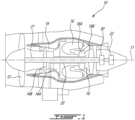
- Fig. 1 illustrates an aircraft engine depicted as a gas turbine engine 10 of a type preferably provided for use in subsonic flight, generally comprising in serial flow communication a fan 12 through which ambient air is propelled, a compressor section 14 for pressurizing the air, a combustor 16 in which the compressed air is mixed with fuel and ignited for generating an annular stream of hot combustion gases, and a turbine section 18 for extracting energy from the combustion gases.
- the fan 12, the compressor section 14, and the turbine section 18 are rotatable about a central axis 11 of the gas turbine engine 10.
- the gas turbine engine 10 comprises a high-pressure spool having a high-pressure shaft 20 drivingly engaging a high-pressure turbine 18A of the turbine section 18 to a high-pressure compressor 14A of the compressor section 14, and a low-pressure spool having a low-pressure shaft 21 drivingly engaging a low-pressure turbine 18B of the turbine section to a low-pressure compressor 14B of the compressor section 14 and drivingly engaged to the fan 12.
- a high-pressure spool having a high-pressure shaft 20 drivingly engaging a high-pressure turbine 18A of the turbine section 18 to a high-pressure compressor 14A of the compressor section 14, and a low-pressure spool having a low-pressure shaft 21 drivingly engaging a low-pressure turbine 18B of the turbine section to a low-pressure compressor 14B of the compressor section 14 and drivingly engaged to the fan 12.
- gas turbine engine 10 may alternatively be another type of engine, for example a turboshaft or a turboprop engine, also generally comprising in serial flow communication a compressor section, a combustor, and a turbine section, and a propeller through which ambient air is propelled.
- a turboshaft or a turboprop engine also generally comprising in serial flow communication a compressor section, a combustor, and a turbine section, and a propeller through which ambient air is propelled.
- the engine 10 is described herein for flight applications, it should be understood that other uses, such as industrial or the like, may apply.
- the compressor section 14 includes a first component 30, which herein corresponds to an impeller 31 of the high-pressure compressor 14A, and a second component 32, which herein corresponds to the low-pressure shaft 21.
- the high-pressure compressor 14A may include an axial compressor instead of the impeller 31. It will be appreciated that the principles of the present disclosure applies to any two components that are coaxial and that are axially overlapping one another. For instance, the two components may be two shafts, a rotor and a stator, and so on.
- the two components 31, 32 may be both rotating, either at the same speed or at different speeds; one of the two components may be rotating while the other is static; both of the two components may be static.
- the impeller 31 is drivingly engaged by the high-pressure shaft 20.
- the first component 30 or impeller 31 is rotatable relative to the second component 32 or low-pressure shaft 21.
- the principles of the present disclosure may also apply to the turbine section 18 of the gas turbine engine 10 as will be described below.
- the impeller 31 compresses an airflow flowing between blades of the impeller 31 and outputs a flow of compressed air at an outlet 31A of the impeller 31.
- a portion of the compressed air exiting the impeller 31 flows to the combustor section 16 for combustion.
- Another portion of the compressed air flows within a secondary air system, which uses the air, for instance, for pressurizing bearing cavities, cooling components, and so on.
- the secondary air system may include a first zone 33 that receives this other portion of the compressed air before delivering it to locations in need of pressurization and/or cooling.
- the compressed air in the first zone 33 flows within a flow passage 34 along flow direction F1.
- the flow passage 34 extends within an annular gap 35 defined radially between a peripheral face 31B circumscribing a bore of the impeller 31 and the low-pressure shaft 21.
- the flow passage 34 leads to a second zone 36 being at a pressure less than that of the first zone 33.
- a seal 37 is used.
- the seal 37 is in fluid flow communication with the flow passage 34 and limits a flow rate of the air flowing along the flow direction F1 from the first zone 33 to the second zone 36.
- the seal 37 extends in a direction having a radial component relative to the central axis 11 from a seal base 37A to a seal end 37B being radially spaced apart from the seal base 37A.
- the seal 37 extends in a radially inward direction.
- the seal 37 is depicted here as a labyrinth seal having a series of axially spaced-apart teeth.
- any suitable seal may be used, such as, for instance, a controlled gap seal, a carbon seal, a brush seal, and so on.
- the seal 37 is secured to the peripheral face 31B of the impeller 31, but may alternatively be secured to the high-pressure shaft 20. In another embodiment, the seal 37 may be secured to the low-pressure shaft 21 and may extend in a radially outward direction.
- the seal 37 defines a seal clearance 37C, which corresponds to a gap defined radially from the seal end 37B to a seal land 37D facing the seal 37.
- the seal land 37D is defined by a face of the low-pressure shaft 21.
- the seal land 37D may be defined by another component, such as a sleeve, secured to the low-pressure shaft 21.
- the seal clearance 37C may be axisymmetric. That is, the seal clearance 37C may be constant all around the central axis 11. However, assembly and manufacturing tolerances of any of these components, or alternatively deflections resulting from engine operation, may create locations around the central axis 11 where the seal clearance 37C is greater than that at other locations.
- the compressed air that flows through the seal 37 is at a high temperature since it went through a compressing process via its passage through the impeller 31. A greater flow rate is expected at the locations where the seal clearance 37C is greater. This, in turn, creates more hot air flowing past certain circumferential portions of either the impeller 31 and the low-pressure shaft 21 and less hot air flowing past other circumferential portions. These components may therefore exhibit circumferential thermal gradients, which may be undesired. These may be further exacerbated because the flow that flows past the seal 37 may tend to stick to the low-pressure shaft 21 because of the Coanda effect.
- the hot air flowing along the flow direction F1 is mixed with cooler air bled from the high-pressure compressor 14A, or bled from any other source, for instance, from the low-pressure compressor 14B. More specifically, in the embodiment shown, a shroud 38 extends circumferentially around the impeller 31.
- the shroud 38 may define a bleed outlet 38A via which air may be bled from the high-pressure compressor 14A for use by the secondary air system.
- a flow of bled air flows around a second flow direction F2 from the bleed outlet 38A and is injected inside the flow passage 34 downstream of the seal 37 relative to flow direction F1.
- a deflector 39 is used and may help in increasing mixing efficiency.
- the deflector 39 may be annularly extending around a full circumference of the low-pressure shaft 21.
- the deflector 39 may be axisymmetric.
- the deflector 39 may include a plurality of deflector sections circumferentially interspaced about the central axis 11. The deflector 39 is located downstream of the seal 37 relative to the air flowing in the flow direction F1 from the first zone 33 to the second zone 36.
- the deflector 39 has a deflector base 39A secured to the low-pressure shaft 21 and a deflector end 39B radially spaced apart from the deflector base 39A.
- the deflector 39 may extend in a radially outward direction relative to the central axis 11.
- a radial height of the deflector 39 is selected to be at least as high as a thickness of a boundary layer of the flow reaching the deflector 39.
- the deflector 39 and the seal 37 therefore extend in radially opposite directions.
- the deflector 39 may break the Coanda effect to deflect the flow in a radially outward direction along a third flow direction F3.
- the deflector 39 therefore extends transversally to a direction of the flow downstream of the seal 37.
- the deflector 39 may therefore facilitate the mixing between the flows flowing along second directions F2 and third direction F3.
- the mix of the cooler bled air providing from the bleed outlet 38A and the hot air from the first zone 33 may flow through an outlet 21A defined by the low-pressure shaft 21.
- This mixture of cooler and hotter air may flow along a fourth flow direction F4 within an internal passage of the low-pressure shaft 21 to reach locations in need of pressurizing and/or cooling. These locations may include, for instance, bearing housings, turbine rotors, turbine shrouds, and so on.
- the outlet 21A may be located downstream of the deflector 39 relative to the flow direction F1.
- the presence of both of the deflector 39 and of the seal 37 may create a radial interference. This may be problematic for assembling parts of the gas turbine engine 10. More specifically, in the present embodiment, the low-pressure shaft 21 may require to be inserted through the bore of the impeller 31. This may be prevented by the deflector that may partially radially overlap the seal.
- this problem may be alleviated by providing a positive radial gap or clearance 40 defined radially between the seal end 37B and the deflector end 39B such that an axial movement of the low-pressure shaft 21 relative to the impeller 31 is permitted during an assembly process that may require the deflector end 39B to pass underneath the seal end 37B.
- the low-pressure shaft 21 defines a recessed section 21B.
- the deflector 39 is secured to the recessed section 21B.
- a radial distance D1 between the recessed section 21B and the seal end 37B is greater than the seal clearance 37C, which is defined between the seal land 37D and the seal end 37B.
- the seal land 37D may be connected to the recessed section 21B via a sloped section 21C.
- An angle A1 defined between the sloped section 21C and the seal land 37D may be selected to avoid the detachment of the flow flowing through the seal 37 and along the sloped section 21C.
- the angle A1 is preferably 45 degrees or less. In some embodiments, the angle A1 ranges from 10 degrees to 15 degrees.
- both of the low-pressure shaft 21 and the peripheral face 31B may define a recessed section to create the radial clearance 40.
- the deflector 39 may be an integral part of the low-pressure shaft 21.
- the deflector 139 defines a curved shape to better redirect the flow flowing past the seal 37 along the flow direction F1. Such a flow deflector 139 may more smoothly deflect the flow.
- the sloped section 121C may smoothly merge to both of the seal land 37D and the recessed section 21B.
- axial ends of the sloped section 121C may be tangential to the seal land 37D and the recessed section 21B.
- the seal 137 is a controlled gap seal. But, as mentioned above, any other type of seal may be used.
- the deflector 39 is secured to the impeller 31 and the seal 37 is secured to the low-pressure shaft 21.
- the recessed and sloped sections 21B, 21C are herein defined by the peripheral face 31B of the bore of the impeller 31.
- the turbine section 18 includes two rotor discs 18C, 18D, which are herein part of the low-pressure turbine 18B, but may alternatively be part of the high-pressure turbine 18A. These two discs may be part of a turbine section comprising one or more additional discs located either upstream, downstream, or both.
- a stator 18E is disposed axially between the two rotor discs 18C, 18D.
- the seal 37 may be secured to a flange 18F of the stator 18E.
- the first component corresponds to the flange 18F and the second component to the low-pressure shaft 21, or alternatively to the high-pressure shaft 20, connecting the two turbine discs 18C, 18D together.
- the two zones at different pressures are disposed on respective opposite sides of the flange 18F of the stator 18E.
- the deflector 39 may be used for mixing a flow of combustion gases ingested along fifth flow direction F5 and a cooling air flow flowing along sixth flow direction F6.
- the air exiting apertures defined through the shaft 21 along the sixth flow direction F6 may be the same air flowing within the shaft along the fourth flow direction F4 ( Fig. 2 ).
- the radial clearance 40 is provided between the seal end and the deflector end.
- this configuration may be provided as part of the fan 12, within the low-pressure compressor 14B, the high-pressure compressor 14A as described above with reference to Fig. 2 , inwardly of the combustor 16, under a diffuser case, within the low-pressure turbine 18B as described above, within the high-pressure turbine 18A, within an exhaust case, and so on.
- the method 800 includes obtaining the first component 31 having the seal 37 extending from a face of the first component 31 to a seal end 37B at 802; obtaining the second component 32 having the deflector 39 extending from a face of the second component 32 to a deflector end 39B at 804; and inserting one of the first component 31 and the second component 32 through the other of the first component 31 and the second component 32 by moving the deflector 39 past the seal 37, the moving of the deflector past the seal permitted by a radial clearance defined radially between the deflector end 39B and the seal end 37B at 806.
- the obtaining of the second component 32 includes obtaining the second component 32 having the recessed section 21B.
- the deflector 39 secured to the recessed section 21B.
- the obtaining of the second component 32 having the recessed section 21B includes obtaining the second component 32 having the sloped section 21C between the seal land 37D and the recessed section 21B.
- the downstream side of the seal may be either a dry cavity, or a wetted cavity (e.g., mixture of oil and air).
- a wetted cavity e.g., mixture of oil and air
Landscapes
- Engineering & Computer Science (AREA)
- Mechanical Engineering (AREA)
- General Engineering & Computer Science (AREA)
- Turbine Rotor Nozzle Sealing (AREA)
- Sealing Using Fluids, Sealing Without Contact, And Removal Of Oil (AREA)
- Structures Of Non-Positive Displacement Pumps (AREA)
Abstract
a rotor (30, 31) defining a bore;
a shaft (21) extending through the bore;
a flow passage (34) in fluid flow communication with an annular gap (35) defined radially between the rotor (30, 31) and the shaft (21), the flow passage (34) fluidly connecting a first zone (33) and a second zone (36);
a seal (37) disposed in the flow passage (34) between the first zone (33) and the second zone (36), the seal (37) extending from a seal base (37A) secured to one of the rotor (30, 31) and the shaft (21) to a seal end (37B) radially spaced apart from the seal base (37A);
a deflector (39) located downstream of the seal (37) relative to a first flow of air flowing from the first zone (33) to the second zone (36) through the seal (37), the deflector (39) extending from a deflector base (39A) secured to the other of the rotor (30, 31) and the shaft (21) to a deflector end (39B) radially spaced apart from the deflector base (39A); and
a radial gap (40) defined radially between the seal end (37B) and the deflector end (39B).
Description
- The application relates generally to aircraft engines and, more particularly, to labyrinth seals used in such engines and assembly features of such engines.
- In an aircraft engine, such as a gas turbine engine, seals are used to separate cavities containing air at different pressures. Seals, such as a labyrinth seal, are typically used to limit leakage of air from one cavity to another, at locations where relative movement between components is either necessary or advisable. A radial clearance of the seal may be non-uniform circumferentially. Hence, a radial gap defined by the seal may be greater at a given circumferential location than at other circumferential locations. This may create a greater flow through the seal at this given circumferential location. In situations where the flow of air is hot (or cold) relative to the downstream cavity, an increased mass flow air at this location may result in a circumferential region of a component downstream of the seal being hotter (or colder) than other circumferential regions. In turn, this may create thermal gradients within the component. Improvements are therefore sought.
- In one aspect, there is provided an aircraft engine comprising: a first component and a second component coaxially mounted about a central axis; a flow passage extending within an annular gap defined radially between the first component and the second component, the flow passage fluidly connecting a first zone to a second zone; a seal disposed in the flow passage between the first zone and the second zone, the seal extending from a seal base secured to the first component to a seal end radially spaced apart from the seal base; a deflector located downstream of the seal relative to a first flow flowing from the first zone to the second zone through the seal, the deflector extending from a deflector base secured to the second component to a deflector end radially spaced apart from the deflector base; and a radial gap defined radially between the seal end and the deflector end.
- The aircraft engine may include any of the following features, in any combinations.
- Optionally, and in accordance with any of the above, the second component defines a recessed section in a radial direction relative to the central axis, the deflector secured to or integral to the recessed section.
- Optionally, and in accordance with any of the above, the second component defines a seal land facing the seal, a radial distance between the recessed section and the seal end greater than a radial clearance defined between the seal land and the seal end.
- Optionally, and in accordance with any of the above, the second component defines a sloped section connecting a seal land facing the seal to the recessed section.
- Optionally, and in accordance with any of the above, an angle defined between the sloped section and the seal land is selected to avoid detachment of the first flow flowing along the sloped section.
- Optionally, and in accordance with any of the above, the flow passage receives the first flow from the first zone, receives a second flow at a temperature different than that of the first flow, the flow passage has an outlet receiving a mixture of the first flow and the second flow.
- Optionally, and in accordance with any of the above, the outlet is located downstream of the deflector relative to the first flow.
- Optionally, and in accordance with any of the above, the seal is a labyrinth seal, a controlled gap seal, a carbon seal, or a brush seal.
- Optionally, and in accordance with any of the above, the first component is located radially outwardly of the second component.
- Optionally, and in accordance with any of the above, the first component is rotating about the central axis.
- Optionally, and in accordance with any of the above, the second component is located radially outwardly of the first component.
- In another aspect, there is provided a compressor section, comprising: a rotor defining a bore; a shaft extending through the bore; a flow passage in fluid flow communication with an annular gap defined radially between the rotor and the shaft, the flow passage fluidly connecting a first zone and a second zone; a seal disposed in the flow passage between the first zone and the second zone, the seal extending from a seal base secured to one of the rotor and the shaft to a seal end radially spaced apart from the seal base; a deflector located downstream of the seal relative to a first flow of air flowing from the first zone to the second zone through the seal, the deflector extending from a deflector base secured to the other of the rotor and the shaft to a deflector end radially spaced apart from the deflector base; and a radial gap defined radially between the seal end and the deflector end.
- In another aspect, there is provided a turbine section, comprising: a rotor defining a bore; a shaft extending through the bore; a flow passage in fluid flow communication with an annular gap defined radially between the rotor and the shaft, the flow passage fluidly connecting a first zone and a second zone; a seal disposed in the flow passage between the first zone and the second zone, the seal extending from a seal base secured to one of the rotor and the shaft to a seal end radially spaced apart from the seal base; a deflector located downstream of the seal relative to a first flow of air flowing from the first zone to the second zone through the seal, the deflector extending from a deflector base secured to the other of the rotor and the shaft to a deflector end radially spaced apart from the deflector base; and a radial gap defined radially between the seal end and the deflector end.
- The compressor section or turbine section may include any of the following optional features, in any combinations.
- Optionally, and in accordance with any of the above, the other of the rotor and the shaft defines a recessed section, the deflector secured to the recessed section.
- Optionally, and in accordance with any of the above, the other of the rotor and the shaft defines a seal land facing the seal, a radial distance between the recessed section and the seal end greater than a radial clearance defined between the seal land and the seal end.
- Optionally, and in accordance with any of the above, the other of the rotor and the shaft defines a sloped section connecting a seal land facing the seal and the recessed section.
- Optionally, and in accordance with any of the above, an angle defined between the sloped section and the seal land is selected to avoid detachment of the first flow of air flowing along the sloped section.
- Optionally, and in accordance with any of the above, the flow passage receives the first flow from the first zone, receives a second flow at a temperature different than that of the first flow, the flow passage has an outlet receiving a mixture of the first flow and the second flow.
- Optionally, and in accordance with any of the above, the outlet is located downstream of the deflector relative to the first flow.
- Optionally, and in accordance with any of the above, the seal is secured to the rotor and the deflector is secured to or integral to the shaft.
- Optionally, and in accordance with any of the above, the compressor section or turbine section may be part of an aircraft engine.
- Reference is now made to the accompanying figures in which:
-
Fig. 1 is a schematic cross sectional view of an aircraft engine depicted as a gas turbine engine; -
Fig. 2 is a schematic view of a compressor section of the gas turbine engine ofFig. 1 illustrating an integration of a seal and a deflector in accordance with one embodiment; -
Fig. 3 is a cross-sectional view of another integration of a seal and a deflector in accordance with another embodiment; -
Fig. 4 is a cross-sectional view of another integration of a seal and a deflector in accordance with another embodiment; -
Fig. 5 is a cross-sectional view of another integration of a seal and a deflector in accordance with still another embodiment; -
Fig. 6 is a cross-sectional view of another integration of a seal and a deflector in accordance with yet another embodiment; -
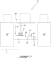
Fig. 7 is a cross-sectional view of a turbine section of the aircraft engine ofFig. 1 ; and -
Fig. 8 is a flowchart illustrating steps of assembling the aircraft engine ofFig. 1 . -
Fig. 1 illustrates an aircraft engine depicted as agas turbine engine 10 of a type preferably provided for use in subsonic flight, generally comprising in serial flow communication afan 12 through which ambient air is propelled, acompressor section 14 for pressurizing the air, acombustor 16 in which the compressed air is mixed with fuel and ignited for generating an annular stream of hot combustion gases, and aturbine section 18 for extracting energy from the combustion gases. Thefan 12, thecompressor section 14, and theturbine section 18 are rotatable about acentral axis 11 of thegas turbine engine 10. In the embodiment shown, thegas turbine engine 10 comprises a high-pressure spool having a high-pressure shaft 20 drivingly engaging a high-pressure turbine 18A of theturbine section 18 to a high-pressure compressor 14A of thecompressor section 14, and a low-pressure spool having a low-pressure shaft 21 drivingly engaging a low-pressure turbine 18B of the turbine section to a low-pressure compressor 14B of thecompressor section 14 and drivingly engaged to thefan 12. It will be understood that the contents of the present disclosure may be applicable to any suitable engines, such as electric hybrid engines and reciprocating engines, such as piston and rotary engines without departing from the scope of the present disclosure. - Although illustrated as a turbofan engine, the
gas turbine engine 10 may alternatively be another type of engine, for example a turboshaft or a turboprop engine, also generally comprising in serial flow communication a compressor section, a combustor, and a turbine section, and a propeller through which ambient air is propelled. In addition, although theengine 10 is described herein for flight applications, it should be understood that other uses, such as industrial or the like, may apply. - Referring now to
Fig. 2 , a portion of thecompressor section 14 is shown. Thecompressor section 14 includes afirst component 30, which herein corresponds to an impeller 31 of the high-pressure compressor 14A, and a second component 32, which herein corresponds to the low-pressure shaft 21. In another embodiment, the high-pressure compressor 14A may include an axial compressor instead of the impeller 31. It will be appreciated that the principles of the present disclosure applies to any two components that are coaxial and that are axially overlapping one another. For instance, the two components may be two shafts, a rotor and a stator, and so on. The two components 31, 32 may be both rotating, either at the same speed or at different speeds; one of the two components may be rotating while the other is static; both of the two components may be static. The impeller 31 is drivingly engaged by the high-pressure shaft 20. Hence, thefirst component 30 or impeller 31 is rotatable relative to the second component 32 or low-pressure shaft 21. The principles of the present disclosure may also apply to theturbine section 18 of thegas turbine engine 10 as will be described below. - In use, the impeller 31 compresses an airflow flowing between blades of the impeller 31 and outputs a flow of compressed air at an
outlet 31A of the impeller 31. A portion of the compressed air exiting the impeller 31 flows to thecombustor section 16 for combustion. Another portion of the compressed air flows within a secondary air system, which uses the air, for instance, for pressurizing bearing cavities, cooling components, and so on. The secondary air system may include afirst zone 33 that receives this other portion of the compressed air before delivering it to locations in need of pressurization and/or cooling. In the embodiment shown, the compressed air in thefirst zone 33 flows within aflow passage 34 along flow direction F1. Theflow passage 34 extends within anannular gap 35 defined radially between aperipheral face 31B circumscribing a bore of the impeller 31 and the low-pressure shaft 21. Theflow passage 34 leads to asecond zone 36 being at a pressure less than that of thefirst zone 33. - To allow relative motion between the impeller 31 and the low-
pressure shaft 21 while limiting a flow between thefirst zone 33 and thesecond zone 36, aseal 37 is used. Theseal 37 is in fluid flow communication with theflow passage 34 and limits a flow rate of the air flowing along the flow direction F1 from thefirst zone 33 to thesecond zone 36. Theseal 37 extends in a direction having a radial component relative to thecentral axis 11 from aseal base 37A to aseal end 37B being radially spaced apart from theseal base 37A. Herein, theseal 37 extends in a radially inward direction. Theseal 37 is depicted here as a labyrinth seal having a series of axially spaced-apart teeth. However, any suitable seal may be used, such as, for instance, a controlled gap seal, a carbon seal, a brush seal, and so on. In the embodiment shown, theseal 37 is secured to theperipheral face 31B of the impeller 31, but may alternatively be secured to the high-pressure shaft 20. In another embodiment, theseal 37 may be secured to the low-pressure shaft 21 and may extend in a radially outward direction. - The
seal 37 defines aseal clearance 37C, which corresponds to a gap defined radially from theseal end 37B to aseal land 37D facing theseal 37. In the present case, theseal land 37D is defined by a face of the low-pressure shaft 21. In some embodiments, theseal land 37D may be defined by another component, such as a sleeve, secured to the low-pressure shaft 21. - The
seal clearance 37C may be axisymmetric. That is, theseal clearance 37C may be constant all around thecentral axis 11. However, assembly and manufacturing tolerances of any of these components, or alternatively deflections resulting from engine operation, may create locations around thecentral axis 11 where theseal clearance 37C is greater than that at other locations. In use, the compressed air that flows through theseal 37 is at a high temperature since it went through a compressing process via its passage through the impeller 31. A greater flow rate is expected at the locations where theseal clearance 37C is greater. This, in turn, creates more hot air flowing past certain circumferential portions of either the impeller 31 and the low-pressure shaft 21 and less hot air flowing past other circumferential portions. These components may therefore exhibit circumferential thermal gradients, which may be undesired. These may be further exacerbated because the flow that flows past theseal 37 may tend to stick to the low-pressure shaft 21 because of the Coanda effect. - The hot air flowing along the flow direction F1 is mixed with cooler air bled from the high-
pressure compressor 14A, or bled from any other source, for instance, from the low-pressure compressor 14B. More specifically, in the embodiment shown, ashroud 38 extends circumferentially around the impeller 31. Theshroud 38 may define ableed outlet 38A via which air may be bled from the high-pressure compressor 14A for use by the secondary air system. A flow of bled air flows around a second flow direction F2 from thebleed outlet 38A and is injected inside theflow passage 34 downstream of theseal 37 relative to flow direction F1. - Because of the uneven circumferential gap and flow distribution at the
seal 37, it may be difficult to mix the cooler air from thebleed outlet 38A with the compressed air from thefirst zone 33. Adeflector 39 is used and may help in increasing mixing efficiency. Thedeflector 39 may be annularly extending around a full circumference of the low-pressure shaft 21. Thedeflector 39 may be axisymmetric. In other embodiments, thedeflector 39 may include a plurality of deflector sections circumferentially interspaced about thecentral axis 11. Thedeflector 39 is located downstream of theseal 37 relative to the air flowing in the flow direction F1 from thefirst zone 33 to thesecond zone 36. Thedeflector 39 has adeflector base 39A secured to the low-pressure shaft 21 and adeflector end 39B radially spaced apart from thedeflector base 39A. Thedeflector 39 may extend in a radially outward direction relative to thecentral axis 11. A radial height of thedeflector 39 is selected to be at least as high as a thickness of a boundary layer of the flow reaching thedeflector 39. Thedeflector 39 and theseal 37 therefore extend in radially opposite directions. Thedeflector 39 may break the Coanda effect to deflect the flow in a radially outward direction along a third flow direction F3. Thedeflector 39 therefore extends transversally to a direction of the flow downstream of theseal 37. Thedeflector 39 may therefore facilitate the mixing between the flows flowing along second directions F2 and third direction F3. - The mix of the cooler bled air providing from the
bleed outlet 38A and the hot air from thefirst zone 33 may flow through anoutlet 21A defined by the low-pressure shaft 21. This mixture of cooler and hotter air may flow along a fourth flow direction F4 within an internal passage of the low-pressure shaft 21 to reach locations in need of pressurizing and/or cooling. These locations may include, for instance, bearing housings, turbine rotors, turbine shrouds, and so on. Theoutlet 21A may be located downstream of thedeflector 39 relative to the flow direction F1. - However, the presence of both of the
deflector 39 and of theseal 37 may create a radial interference. This may be problematic for assembling parts of thegas turbine engine 10. More specifically, in the present embodiment, the low-pressure shaft 21 may require to be inserted through the bore of the impeller 31. This may be prevented by the deflector that may partially radially overlap the seal. - In the present embodiment, this problem may be alleviated by providing a positive radial gap or
clearance 40 defined radially between theseal end 37B and thedeflector end 39B such that an axial movement of the low-pressure shaft 21 relative to the impeller 31 is permitted during an assembly process that may require thedeflector end 39B to pass underneath theseal end 37B. - In the embodiment shown, the low-
pressure shaft 21 defines a recessedsection 21B. Thedeflector 39 is secured to the recessedsection 21B. A radial distance D1 between the recessedsection 21B and theseal end 37B is greater than theseal clearance 37C, which is defined between theseal land 37D and theseal end 37B. Theseal land 37D may be connected to the recessedsection 21B via asloped section 21C. An angle A1 defined between thesloped section 21C and theseal land 37D may be selected to avoid the detachment of the flow flowing through theseal 37 and along the slopedsection 21C. The angle A1 is preferably 45 degrees or less. In some embodiments, the angle A1 ranges from 10 degrees to 15 degrees. - In some other embodiments, both of the low-
pressure shaft 21 and theperipheral face 31B may define a recessed section to create theradial clearance 40. Thedeflector 39 may be an integral part of the low-pressure shaft 21. - Referring now to
Fig. 3 , another embodiment of a deflector is shown at 139. As illustrated, thedeflector 139 defines a curved shape to better redirect the flow flowing past theseal 37 along the flow direction F1. Such aflow deflector 139 may more smoothly deflect the flow. - Referring now to
Fig. 4 , in the embodiment shown, the slopedsection 121C may smoothly merge to both of theseal land 37D and the recessedsection 21B. In other words, axial ends of the slopedsection 121C may be tangential to theseal land 37D and the recessedsection 21B. - Referring now to
Fig. 5 , in the embodiment shown, theseal 137 is a controlled gap seal. But, as mentioned above, any other type of seal may be used. - Referring now to
Fig. 6 , in the present embodiment, thedeflector 39 is secured to the impeller 31 and theseal 37 is secured to the low-pressure shaft 21. The recessed and slopedsections peripheral face 31B of the bore of the impeller 31. - Referring now to
Fig. 7 , another implementation of theseal 37 anddeflector 39 is shown in theturbine section 18 of thegas turbine engine 10. As shown, theturbine section 18 includes tworotor discs pressure turbine 18B, but may alternatively be part of the high-pressure turbine 18A. These two discs may be part of a turbine section comprising one or more additional discs located either upstream, downstream, or both. As shown, astator 18E is disposed axially between the tworotor discs seal 37 may be secured to aflange 18F of thestator 18E. In this embodiment, the first component corresponds to theflange 18F and the second component to the low-pressure shaft 21, or alternatively to the high-pressure shaft 20, connecting the twoturbine discs flange 18F of thestator 18E. Thedeflector 39 may be used for mixing a flow of combustion gases ingested along fifth flow direction F5 and a cooling air flow flowing along sixth flow direction F6. The air exiting apertures defined through theshaft 21 along the sixth flow direction F6 may be the same air flowing within the shaft along the fourth flow direction F4 (Fig. 2 ). Theradial clearance 40 is provided between the seal end and the deflector end. - It will be appreciated that the principles of the present disclosure, including the radial clearance between the seal end and the deflector end, may be provided at a plurality of locations inside the
gas turbine engine 10. For instance, this configuration may be provided as part of thefan 12, within the low-pressure compressor 14B, the high-pressure compressor 14A as described above with reference toFig. 2 , inwardly of thecombustor 16, under a diffuser case, within the low-pressure turbine 18B as described above, within the high-pressure turbine 18A, within an exhaust case, and so on. - Referring now to
Fig. 8 , a method of assembling thegas turbine engine 10 is shown at 800. Themethod 800 includes obtaining the first component 31 having theseal 37 extending from a face of the first component 31 to aseal end 37B at 802; obtaining the second component 32 having thedeflector 39 extending from a face of the second component 32 to adeflector end 39B at 804; and inserting one of the first component 31 and the second component 32 through the other of the first component 31 and the second component 32 by moving thedeflector 39 past theseal 37, the moving of the deflector past the seal permitted by a radial clearance defined radially between thedeflector end 39B and theseal end 37B at 806. - In the embodiment shown, the obtaining of the second component 32 includes obtaining the second component 32 having the recessed
section 21B. Thedeflector 39 secured to the recessedsection 21B. A radial distance between the recessedsection 21B and theseal end 37B greater than a radial clearance defined between theseal land 37D and theseal end 37B. - Herein, the obtaining of the second component 32 having the recessed
section 21B includes obtaining the second component 32 having the slopedsection 21C between theseal land 37D and the recessedsection 21B. - The embodiments described in this document provide non-limiting examples of possible implementations of the present technology. Upon review of the present disclosure, a person of ordinary skill in the art will recognize that changes may be made to the embodiments described herein without departing from the scope of the present technology. In some other embodiments, the downstream side of the seal may be either a dry cavity, or a wetted cavity (e.g., mixture of oil and air). Yet further modifications could be implemented by a person of ordinary skill in the art in view of the present disclosure, which modifications would be within the scope of the present technology.
Claims (11)
- A compressor section (14), comprising:a rotor (30, 31) defining a bore;a shaft (21) extending through the bore;a flow passage (34) in fluid flow communication with an annular gap (35) defined radially between the rotor (30, 31) and the shaft (21), the flow passage (34) fluidly connecting a first zone (33) and a second zone (36);a seal (37) disposed in the flow passage (34) between the first zone (33) and the second zone (36), the seal (37) extending from a seal base (37A) secured to one of the rotor (30, 31) and the shaft (21) to a seal end (37B) radially spaced apart from the seal base (37A);a deflector (39) located downstream of the seal (37) relative to a first flow of air flowing from the first zone (33) to the second zone (36) through the seal (37), the deflector (39) extending from a deflector base (39A) secured to the other of the rotor (30, 31) and the shaft (21) to a deflector end (39B) radially spaced apart from the deflector base (39A); anda radial gap (40) defined radially between the seal end (37B) and the deflector end (39B).
- The compressor section (14) of claim 1, wherein the other of the rotor (30, 31) and the shaft (21, 32) defines a recessed section (21B), the deflector (39) secured to the recessed section (21B).
- The compressor section (14) of claim 2, wherein the other of the rotor and the shaft (21, 32) defines a seal land (37D) facing the seal (37), a radial distance (D1) between the recessed section (21B) and the seal end (37B) being greater than a radial clearance (40) defined between the seal land (37D) and the seal end (37B).
- The compressor section (14) of claim 2 or 3, wherein the other of the rotor and the shaft (21, 32) defines a sloped section (21C) connecting a or the seal land (37D) facing the seal (37) and the recessed section (21B).
- The compressor section (14) of claim 4, wherein an angle (A1) defined between the sloped section (21C) and the seal land (37D) is selected to avoid detachment of the first flow of air flowing along the sloped section (21C).
- The compressor section (14) of any preceding claim, wherein the flow passage (34) receives the first flow from the first zone (33), receives a second flow at a temperature different than that of the first flow, and the flow passage (34) has an outlet (31A) receiving a mixture of the first flow and the second flow.
- The compressor section (14) of claim 6, wherein the outlet (31A) is located downstream of the deflector (39) relative to the first flow.
- The compressor section (14) of any preceding claim, wherein the seal (37) is secured to the rotor and the deflector (39) is secured to or integral to the shaft (21).
- The compressor section (14) of any preceding claim, wherein the seal (37) is a labyrinth seal, a controlled gap seal, a carbon seal, or a brush seal.
- An aircraft engine (10) comprising a compressor section (14) as defined in any preceding claim.
- A method (800) comprising:obtaining (802) a first component (30, 31) having a seal (37) extending from a face of the first component (30, 31) to a seal end (37B);obtaining (804) a second component (21, 32) having a deflector (39) extending from a face of the second component (32) to a deflector end (39B); andinserting (806) one of the first component (30, 31) and the second component (32) through the other of the first component (30, 31) and the second component (32) by moving the deflector (39) past the seal (37), the moving of the deflector (39) past the seal (37) permitted by a radial clearance (40) defined radially between the deflector end (39B) and the seal end (37B).
Applications Claiming Priority (1)
| Application Number | Priority Date | Filing Date | Title |
|---|---|---|---|
| US17/656,813 US11692451B1 (en) | 2022-03-28 | 2022-03-28 | Aircraft engine with radial clearance between seal and deflector |
Publications (2)
| Publication Number | Publication Date |
|---|---|
| EP4293200A2 true EP4293200A2 (en) | 2023-12-20 |
| EP4293200A3 EP4293200A3 (en) | 2024-02-21 |
Family
ID=85776141
Family Applications (1)
| Application Number | Title | Priority Date | Filing Date |
|---|---|---|---|
| EP23164477.4A Pending EP4293200A3 (en) | 2022-03-28 | 2023-03-27 | Aircraft engine with radial clearance between seal and deflector |
Country Status (3)
| Country | Link |
|---|---|
| US (1) | US11692451B1 (en) |
| EP (1) | EP4293200A3 (en) |
| CA (1) | CA3193881A1 (en) |
Cited By (1)
| Publication number | Priority date | Publication date | Assignee | Title |
|---|---|---|---|---|
| EP4703609A1 (en) * | 2024-09-03 | 2026-03-04 | MTU Aero Engines AG | Sealing device, in particular sealing device of a turbomachine |
Family Cites Families (15)
| Publication number | Priority date | Publication date | Assignee | Title |
|---|---|---|---|---|
| US4046388A (en) * | 1976-03-09 | 1977-09-06 | Westinghouse Electric Corporation | Seal arrangement utilizing deflector seals of reduced radial dimension |
| DE3523469A1 (en) * | 1985-07-01 | 1987-01-08 | Bbc Brown Boveri & Cie | Contact-free controlled-gap seal for turbo-machines |
| US5211535A (en) | 1991-12-30 | 1993-05-18 | General Electric Company | Labyrinth seals for gas turbine engine |
| US5218816A (en) * | 1992-01-28 | 1993-06-15 | General Electric Company | Seal exit flow discourager |
| US7001145B2 (en) * | 2003-11-20 | 2006-02-21 | General Electric Company | Seal assembly for turbine, bucket/turbine including same, method for sealing interface between rotating and stationary components of a turbine |
| JP4412081B2 (en) * | 2004-07-07 | 2010-02-10 | 株式会社日立製作所 | Gas turbine and gas turbine cooling method |
| FR2904037B1 (en) * | 2006-07-19 | 2010-11-12 | Snecma | VENTILATION OF A DOWNWARD CAVITY OF CENTRIFUGAL COMPRESSOR WHEEL |
| GB201013004D0 (en) | 2010-08-03 | 2010-09-15 | Rolls Royce Plc | A seal assembly |
| JP5709447B2 (en) * | 2010-09-28 | 2015-04-30 | 三菱日立パワーシステムズ株式会社 | Turbine |
| US20130189107A1 (en) * | 2012-01-24 | 2013-07-25 | General Electric Company | Turbine Packing Deflector |
| US10260524B2 (en) * | 2013-10-02 | 2019-04-16 | United Technologies Corporation | Gas turbine engine with compressor disk deflectors |
| GB201419766D0 (en) * | 2014-11-06 | 2014-12-24 | Rolls Royce Plc | A sealing arrangement for a gas turbine engine |
| DE112018002978T5 (en) * | 2017-06-12 | 2020-02-20 | Mitsubishi Hitachi Power Systems, Ltd. | Axialströmungsdrehmaschine |
| US10514102B2 (en) * | 2017-07-14 | 2019-12-24 | United Technologies Corporation | Intershaft bladelet seal |
| FR3099788B1 (en) * | 2019-08-06 | 2021-09-03 | Safran Aircraft Engines | Abradable turbomachine turbine comprising a wear face provided with flow straighteners |
-
2022
- 2022-03-28 US US17/656,813 patent/US11692451B1/en active Active
-
2023
- 2023-03-22 CA CA3193881A patent/CA3193881A1/en active Pending
- 2023-03-27 EP EP23164477.4A patent/EP4293200A3/en active Pending
Cited By (1)
| Publication number | Priority date | Publication date | Assignee | Title |
|---|---|---|---|---|
| EP4703609A1 (en) * | 2024-09-03 | 2026-03-04 | MTU Aero Engines AG | Sealing device, in particular sealing device of a turbomachine |
Also Published As
| Publication number | Publication date |
|---|---|
| EP4293200A3 (en) | 2024-02-21 |
| CA3193881A1 (en) | 2023-09-28 |
| US11692451B1 (en) | 2023-07-04 |
Similar Documents
| Publication | Publication Date | Title |
|---|---|---|
| US10982559B2 (en) | Spline seal with cooling features for turbine engines | |
| US9879603B2 (en) | Axial flow machine cooling system | |
| US5466123A (en) | Gas turbine engine turbine | |
| US10443422B2 (en) | Gas turbine engine with a rim seal between the rotor and stator | |
| US6916154B2 (en) | Diametrically energized piston ring | |
| US20140119883A1 (en) | Bleed flow passage | |
| CN113623023A (en) | Pressure regulated piston seal for gas turbine combustor liner | |
| US10408075B2 (en) | Turbine engine with a rim seal between the rotor and stator | |
| US11143048B2 (en) | Labyrinth seal with variable tooth heights | |
| WO2019131011A1 (en) | Aircraft gas turbine, and moving blade of aircraft gas turbine | |
| US11692451B1 (en) | Aircraft engine with radial clearance between seal and deflector | |
| CN107060897B (en) | Slotted Seals for Gas Turbine Engines | |
| CA2992684C (en) | Turbine housing assembly | |
| US10570767B2 (en) | Gas turbine engine with a cooling fluid path | |
| US12286885B1 (en) | Turbine assembly with confronting vane and turbine shroud segment | |
| US12270546B2 (en) | Dome-deflector assembly for a combustor of a gas turbine | |
| US12421862B2 (en) | Turbine shroud assembly with angled cooling holes | |
| EP4571192A1 (en) | Fuel spray nozzle for a gas turbine engine | |
| US12146417B2 (en) | Turbine shroud with ceramic matrix composite blade track segments and method of assembly | |
| CN114096739B (en) | Seal assembly in a gas turbine engine | |
| EP3312392A1 (en) | Turbine shroud and seal system | |
| US20090060736A1 (en) | Compressor |
Legal Events
| Date | Code | Title | Description |
|---|---|---|---|
| PUAI | Public reference made under article 153(3) epc to a published international application that has entered the european phase |
Free format text: ORIGINAL CODE: 0009012 |
|
| STAA | Information on the status of an ep patent application or granted ep patent |
Free format text: STATUS: THE APPLICATION HAS BEEN PUBLISHED |
|
| AK | Designated contracting states |
Kind code of ref document: A2 Designated state(s): AL AT BE BG CH CY CZ DE DK EE ES FI FR GB GR HR HU IE IS IT LI LT LU LV MC ME MK MT NL NO PL PT RO RS SE SI SK SM TR |
|
| PUAL | Search report despatched |
Free format text: ORIGINAL CODE: 0009013 |
|
| AK | Designated contracting states |
Kind code of ref document: A3 Designated state(s): AL AT BE BG CH CY CZ DE DK EE ES FI FR GB GR HR HU IE IS IT LI LT LU LV MC ME MK MT NL NO PL PT RO RS SE SI SK SM TR |
|
| RIC1 | Information provided on ipc code assigned before grant |
Ipc: F01D 11/02 20060101AFI20240117BHEP |
|
| STAA | Information on the status of an ep patent application or granted ep patent |
Free format text: STATUS: REQUEST FOR EXAMINATION WAS MADE |
|
| 17P | Request for examination filed |
Effective date: 20240821 |
|
| RBV | Designated contracting states (corrected) |
Designated state(s): AL AT BE BG CH CY CZ DE DK EE ES FI FR GB GR HR HU IE IS IT LI LT LU LV MC ME MK MT NL NO PL PT RO RS SE SI SK SM TR |
|
| GRAP | Despatch of communication of intention to grant a patent |
Free format text: ORIGINAL CODE: EPIDOSNIGR1 |
|
| STAA | Information on the status of an ep patent application or granted ep patent |
Free format text: STATUS: GRANT OF PATENT IS INTENDED |
|
| INTG | Intention to grant announced |
Effective date: 20260206 |