EP4292999A1 - Oxidation protection for carbon-carbon composites - Google Patents
Oxidation protection for carbon-carbon composites Download PDFInfo
- Publication number
- EP4292999A1 EP4292999A1 EP23179864.6A EP23179864A EP4292999A1 EP 4292999 A1 EP4292999 A1 EP 4292999A1 EP 23179864 A EP23179864 A EP 23179864A EP 4292999 A1 EP4292999 A1 EP 4292999A1
- Authority
- EP
- European Patent Office
- Prior art keywords
- ceramic layer
- slurry
- composite structure
- sealing
- various embodiments
- Prior art date
- Legal status (The legal status is an assumption and is not a legal conclusion. Google has not performed a legal analysis and makes no representation as to the accuracy of the status listed.)
- Granted
Links
Images



Classifications
-
- C—CHEMISTRY; METALLURGY
- C04—CEMENTS; CONCRETE; ARTIFICIAL STONE; CERAMICS; REFRACTORIES
- C04B—LIME, MAGNESIA; SLAG; CEMENTS; COMPOSITIONS THEREOF, e.g. MORTARS, CONCRETE OR LIKE BUILDING MATERIALS; ARTIFICIAL STONE; CERAMICS; REFRACTORIES; TREATMENT OF NATURAL STONE
- C04B35/00—Shaped ceramic products characterised by their composition; Ceramics compositions; Processing powders of inorganic compounds preparatory to the manufacturing of ceramic products
- C04B35/622—Forming processes; Processing powders of inorganic compounds preparatory to the manufacturing of ceramic products
- C04B35/62222—Forming processes; Processing powders of inorganic compounds preparatory to the manufacturing of ceramic products obtaining ceramic coatings
-
- C—CHEMISTRY; METALLURGY
- C04—CEMENTS; CONCRETE; ARTIFICIAL STONE; CERAMICS; REFRACTORIES
- C04B—LIME, MAGNESIA; SLAG; CEMENTS; COMPOSITIONS THEREOF, e.g. MORTARS, CONCRETE OR LIKE BUILDING MATERIALS; ARTIFICIAL STONE; CERAMICS; REFRACTORIES; TREATMENT OF NATURAL STONE
- C04B41/00—After-treatment of mortars, concrete, artificial stone or ceramics; Treatment of natural stone
- C04B41/009—After-treatment of mortars, concrete, artificial stone or ceramics; Treatment of natural stone characterised by the material treated
-
- C—CHEMISTRY; METALLURGY
- C04—CEMENTS; CONCRETE; ARTIFICIAL STONE; CERAMICS; REFRACTORIES
- C04B—LIME, MAGNESIA; SLAG; CEMENTS; COMPOSITIONS THEREOF, e.g. MORTARS, CONCRETE OR LIKE BUILDING MATERIALS; ARTIFICIAL STONE; CERAMICS; REFRACTORIES; TREATMENT OF NATURAL STONE
- C04B35/00—Shaped ceramic products characterised by their composition; Ceramics compositions; Processing powders of inorganic compounds preparatory to the manufacturing of ceramic products
- C04B35/515—Shaped ceramic products characterised by their composition; Ceramics compositions; Processing powders of inorganic compounds preparatory to the manufacturing of ceramic products based on non-oxide ceramics
- C04B35/56—Shaped ceramic products characterised by their composition; Ceramics compositions; Processing powders of inorganic compounds preparatory to the manufacturing of ceramic products based on non-oxide ceramics based on carbides or oxycarbides
- C04B35/565—Shaped ceramic products characterised by their composition; Ceramics compositions; Processing powders of inorganic compounds preparatory to the manufacturing of ceramic products based on non-oxide ceramics based on carbides or oxycarbides based on silicon carbide
-
- C—CHEMISTRY; METALLURGY
- C04—CEMENTS; CONCRETE; ARTIFICIAL STONE; CERAMICS; REFRACTORIES
- C04B—LIME, MAGNESIA; SLAG; CEMENTS; COMPOSITIONS THEREOF, e.g. MORTARS, CONCRETE OR LIKE BUILDING MATERIALS; ARTIFICIAL STONE; CERAMICS; REFRACTORIES; TREATMENT OF NATURAL STONE
- C04B41/00—After-treatment of mortars, concrete, artificial stone or ceramics; Treatment of natural stone
- C04B41/45—Coating or impregnating, e.g. injection in masonry, partial coating of green or fired ceramics, organic coating compositions for adhering together two concrete elements
- C04B41/50—Coating or impregnating, e.g. injection in masonry, partial coating of green or fired ceramics, organic coating compositions for adhering together two concrete elements with inorganic materials
- C04B41/5022—Coating or impregnating, e.g. injection in masonry, partial coating of green or fired ceramics, organic coating compositions for adhering together two concrete elements with inorganic materials with vitreous materials
-
- C—CHEMISTRY; METALLURGY
- C04—CEMENTS; CONCRETE; ARTIFICIAL STONE; CERAMICS; REFRACTORIES
- C04B—LIME, MAGNESIA; SLAG; CEMENTS; COMPOSITIONS THEREOF, e.g. MORTARS, CONCRETE OR LIKE BUILDING MATERIALS; ARTIFICIAL STONE; CERAMICS; REFRACTORIES; TREATMENT OF NATURAL STONE
- C04B41/00—After-treatment of mortars, concrete, artificial stone or ceramics; Treatment of natural stone
- C04B41/45—Coating or impregnating, e.g. injection in masonry, partial coating of green or fired ceramics, organic coating compositions for adhering together two concrete elements
- C04B41/50—Coating or impregnating, e.g. injection in masonry, partial coating of green or fired ceramics, organic coating compositions for adhering together two concrete elements with inorganic materials
- C04B41/5053—Coating or impregnating, e.g. injection in masonry, partial coating of green or fired ceramics, organic coating compositions for adhering together two concrete elements with inorganic materials non-oxide ceramics
- C04B41/5057—Carbides
- C04B41/5059—Silicon carbide
-
- C—CHEMISTRY; METALLURGY
- C04—CEMENTS; CONCRETE; ARTIFICIAL STONE; CERAMICS; REFRACTORIES
- C04B—LIME, MAGNESIA; SLAG; CEMENTS; COMPOSITIONS THEREOF, e.g. MORTARS, CONCRETE OR LIKE BUILDING MATERIALS; ARTIFICIAL STONE; CERAMICS; REFRACTORIES; TREATMENT OF NATURAL STONE
- C04B41/00—After-treatment of mortars, concrete, artificial stone or ceramics; Treatment of natural stone
- C04B41/45—Coating or impregnating, e.g. injection in masonry, partial coating of green or fired ceramics, organic coating compositions for adhering together two concrete elements
- C04B41/52—Multiple coating or impregnating multiple coating or impregnating with the same composition or with compositions only differing in the concentration of the constituents, is classified as single coating or impregnation
-
- C—CHEMISTRY; METALLURGY
- C04—CEMENTS; CONCRETE; ARTIFICIAL STONE; CERAMICS; REFRACTORIES
- C04B—LIME, MAGNESIA; SLAG; CEMENTS; COMPOSITIONS THEREOF, e.g. MORTARS, CONCRETE OR LIKE BUILDING MATERIALS; ARTIFICIAL STONE; CERAMICS; REFRACTORIES; TREATMENT OF NATURAL STONE
- C04B41/00—After-treatment of mortars, concrete, artificial stone or ceramics; Treatment of natural stone
- C04B41/80—After-treatment of mortars, concrete, artificial stone or ceramics; Treatment of natural stone of only ceramics
- C04B41/81—Coating or impregnation
- C04B41/89—Coating or impregnation for obtaining at least two superposed coatings having different compositions
-
- F—MECHANICAL ENGINEERING; LIGHTING; HEATING; WEAPONS; BLASTING
- F16—ENGINEERING ELEMENTS AND UNITS; GENERAL MEASURES FOR PRODUCING AND MAINTAINING EFFECTIVE FUNCTIONING OF MACHINES OR INSTALLATIONS; THERMAL INSULATION IN GENERAL
- F16D—COUPLINGS FOR TRANSMITTING ROTATION; CLUTCHES; BRAKES
- F16D55/00—Brakes with substantially-radial braking surfaces pressed together in axial direction, e.g. disc brakes
- F16D55/24—Brakes with substantially-radial braking surfaces pressed together in axial direction, e.g. disc brakes with a plurality of axially-movable discs, lamellae, or pads, pressed from one side towards an axially-located member
-
- F—MECHANICAL ENGINEERING; LIGHTING; HEATING; WEAPONS; BLASTING
- F16—ENGINEERING ELEMENTS AND UNITS; GENERAL MEASURES FOR PRODUCING AND MAINTAINING EFFECTIVE FUNCTIONING OF MACHINES OR INSTALLATIONS; THERMAL INSULATION IN GENERAL
- F16D—COUPLINGS FOR TRANSMITTING ROTATION; CLUTCHES; BRAKES
- F16D65/00—Parts or details
- F16D65/14—Actuating mechanisms for brakes; Means for initiating operation at a predetermined position
- F16D65/16—Actuating mechanisms for brakes; Means for initiating operation at a predetermined position arranged in or on the brake
- F16D65/18—Actuating mechanisms for brakes; Means for initiating operation at a predetermined position arranged in or on the brake adapted for drawing members together, e.g. for disc brakes
- F16D65/186—Actuating mechanisms for brakes; Means for initiating operation at a predetermined position arranged in or on the brake adapted for drawing members together, e.g. for disc brakes with full-face force-applying member, e.g. annular
-
- F—MECHANICAL ENGINEERING; LIGHTING; HEATING; WEAPONS; BLASTING
- F16—ENGINEERING ELEMENTS AND UNITS; GENERAL MEASURES FOR PRODUCING AND MAINTAINING EFFECTIVE FUNCTIONING OF MACHINES OR INSTALLATIONS; THERMAL INSULATION IN GENERAL
- F16D—COUPLINGS FOR TRANSMITTING ROTATION; CLUTCHES; BRAKES
- F16D69/00—Friction linings; Attachment thereof; Selection of coacting friction substances or surfaces
- F16D69/02—Composition of linings ; Methods of manufacturing
- F16D69/023—Composite materials containing carbon and carbon fibres or fibres made of carbonizable material
-
- C—CHEMISTRY; METALLURGY
- C04—CEMENTS; CONCRETE; ARTIFICIAL STONE; CERAMICS; REFRACTORIES
- C04B—LIME, MAGNESIA; SLAG; CEMENTS; COMPOSITIONS THEREOF, e.g. MORTARS, CONCRETE OR LIKE BUILDING MATERIALS; ARTIFICIAL STONE; CERAMICS; REFRACTORIES; TREATMENT OF NATURAL STONE
- C04B2111/00—Mortars, concrete or artificial stone or mixtures to prepare them, characterised by specific function, property or use
- C04B2111/00241—Physical properties of the materials not provided for elsewhere in C04B2111/00
- C04B2111/00362—Friction materials, e.g. used as brake linings, anti-skid materials
-
- C—CHEMISTRY; METALLURGY
- C04—CEMENTS; CONCRETE; ARTIFICIAL STONE; CERAMICS; REFRACTORIES
- C04B—LIME, MAGNESIA; SLAG; CEMENTS; COMPOSITIONS THEREOF, e.g. MORTARS, CONCRETE OR LIKE BUILDING MATERIALS; ARTIFICIAL STONE; CERAMICS; REFRACTORIES; TREATMENT OF NATURAL STONE
- C04B2235/00—Aspects relating to ceramic starting mixtures or sintered ceramic products
- C04B2235/02—Composition of constituents of the starting material or of secondary phases of the final product
- C04B2235/30—Constituents and secondary phases not being of a fibrous nature
- C04B2235/38—Non-oxide ceramic constituents or additives
- C04B2235/3817—Carbides
- C04B2235/3826—Silicon carbides
-
- C—CHEMISTRY; METALLURGY
- C04—CEMENTS; CONCRETE; ARTIFICIAL STONE; CERAMICS; REFRACTORIES
- C04B—LIME, MAGNESIA; SLAG; CEMENTS; COMPOSITIONS THEREOF, e.g. MORTARS, CONCRETE OR LIKE BUILDING MATERIALS; ARTIFICIAL STONE; CERAMICS; REFRACTORIES; TREATMENT OF NATURAL STONE
- C04B2235/00—Aspects relating to ceramic starting mixtures or sintered ceramic products
- C04B2235/02—Composition of constituents of the starting material or of secondary phases of the final product
- C04B2235/30—Constituents and secondary phases not being of a fibrous nature
- C04B2235/40—Metallic constituents or additives not added as binding phase
- C04B2235/402—Aluminium
-
- C—CHEMISTRY; METALLURGY
- C04—CEMENTS; CONCRETE; ARTIFICIAL STONE; CERAMICS; REFRACTORIES
- C04B—LIME, MAGNESIA; SLAG; CEMENTS; COMPOSITIONS THEREOF, e.g. MORTARS, CONCRETE OR LIKE BUILDING MATERIALS; ARTIFICIAL STONE; CERAMICS; REFRACTORIES; TREATMENT OF NATURAL STONE
- C04B2235/00—Aspects relating to ceramic starting mixtures or sintered ceramic products
- C04B2235/70—Aspects relating to sintered or melt-casted ceramic products
- C04B2235/96—Properties of ceramic products, e.g. mechanical properties such as strength, toughness, wear resistance
- C04B2235/963—Surface properties, e.g. surface roughness
-
- C—CHEMISTRY; METALLURGY
- C04—CEMENTS; CONCRETE; ARTIFICIAL STONE; CERAMICS; REFRACTORIES
- C04B—LIME, MAGNESIA; SLAG; CEMENTS; COMPOSITIONS THEREOF, e.g. MORTARS, CONCRETE OR LIKE BUILDING MATERIALS; ARTIFICIAL STONE; CERAMICS; REFRACTORIES; TREATMENT OF NATURAL STONE
- C04B2235/00—Aspects relating to ceramic starting mixtures or sintered ceramic products
- C04B2235/70—Aspects relating to sintered or melt-casted ceramic products
- C04B2235/96—Properties of ceramic products, e.g. mechanical properties such as strength, toughness, wear resistance
- C04B2235/9669—Resistance against chemicals, e.g. against molten glass or molten salts
- C04B2235/9684—Oxidation resistance
-
- F—MECHANICAL ENGINEERING; LIGHTING; HEATING; WEAPONS; BLASTING
- F16—ENGINEERING ELEMENTS AND UNITS; GENERAL MEASURES FOR PRODUCING AND MAINTAINING EFFECTIVE FUNCTIONING OF MACHINES OR INSTALLATIONS; THERMAL INSULATION IN GENERAL
- F16D—COUPLINGS FOR TRANSMITTING ROTATION; CLUTCHES; BRAKES
- F16D2250/00—Manufacturing; Assembly
- F16D2250/0038—Surface treatment
- F16D2250/0046—Coating
Definitions
- the present disclosure relates generally to composites and, more specifically, to oxidation protection systems for carbon-carbon composite structures.
- Oxidation protection systems for carbon-carbon composites are typically designed to minimize loss of carbon material due to oxidation at operating conditions, which include temperatures of 800°C (1472°F) or higher.
- Layers comprising ceramic materials within an oxidation protection system that are deposited onto a substrate by chemical vapor deposition (“CVD") may provide desirable oxidation protection.
- CVD processes may be expensive and cost-prohibitive.
- a method for forming an oxidation protection system on a composite structure comprising applying a ceramic layer slurry to the composite structure, wherein the ceramic layer slurry comprises aluminum and silicon carbide in a sol, and heating the composite structure to form a ceramic layer on the composite structure, wherein the ceramic layer comprises between 1% and 20% alumina by weight.
- the sol comprises methyltrimethoxysilane and water.
- the method further comprises applying a sealing slurry to the composite structure, wherein the sealing slurry comprises a sealing pre-slurry composition and a sealing carrier fluid, wherein the sealing pre-slurry composition comprises a sealing glass composition, and heating the composite structure to form a sealing layer on the ceramic layer.
- the sealing glass composition is represented by a formula a(A' 2 O) x (P 2 O 5 ) y1 b(G f O) y2 c(A"O) z .
- A' is selected from: lithium, sodium, potassium, rubidium, cesium, and mixtures thereof.
- G f is selected from: boron, silicon, sulfur, germanium, arsenic, antimony, and mixtures thereof.
- A" is selected from: vanadium, aluminum, tin, titanium, chromium, manganese, iron, cobalt, nickel, copper, mercury, zinc, thulium, lead, zirconium, lanthanum, cerium, praseodymium, neodymium, samarium, europium, gadolinium, terbium, dysprosium, holmium, erbium, thulium, ytterbium, actinium, thorium, uranium, yttrium, gallium, magnesium, calcium, strontium, barium, tin, bismuth, cadmium, and mixtures thereof.
- a is a number in a range from 1 to about 5.
- b is a number in a range from 0 to about 10.
- c is a number in a range from 0 to about 30.
- x is a number in a range from about 0.050 to about 0.500.
- yi is a number in a range from about 0.100 to about 0.950.
- y 2 is a number in a range from 0 to about 0.20.
- the method further comprises preparing the ceramic layer slurry by combining methyltrimethoxysilane and water to form the sol and mixing aluminum powder and silicon carbide powder in the sol.
- the ceramic layer slurry comprises between 1% and 10% by weight aluminum powder.
- the ceramic layer slurry comprises between 10% and 50% by weight silicon carbide powder.
- the ceramic layer comprises between 1% and 15% by weight alumina.
- the ceramic layer comprises between 50% and 80% by weight silicon carbide.
- the ceramic layer comprises between 10% and 30% by weight silicon oxycarbide.
- the method further comprises applying a boron slurry to the composite structure prior to the applying the ceramic layer slurry.
- the method further comprises forming the boron slurry by combining boron carbide and a carrier fluid.
- the method further comprises applying a pretreating composition to the composite structure prior to applying the boron slurry.
- applying the pretreating composition to the composite structure comprises applying a first pretreating composition comprising aluminum oxide in water to the composite structure, heating the composite structure to a temperature sufficient remove the water and fix the aluminum oxide in place.
- applying the pretreating composition to the composite structure further comprises applying a second pretreating composition.
- the second pretreating composition comprises phosphoric acid and at least one of aluminum phosphate, aluminum hydroxide, or aluminum oxide.
- the second pretreating composition comprises ammonium dihydrogen phosphate.
- the second pretreating composition comprises aluminum orthophosphate.
- the second pretreating composition comprises aluminum phosphate.
- the oxidation protection system disposed on an outer surface of a substrate.
- the oxidation protection system comprises a ceramic layer comprising between 1% and 20% by weight alumina, between 50% and 80% silicon carbide, and between 10% and 30% by weight silicon oxycarbide, and a sealing layer comprising a sealing glass composition located over the ceramic layer.
- the oxidation protection system further comprises a boron layer formed between the ceramic layer and the substrate.
- the ceramic layer comprises about 5% by weight alumina, about 75% by weight silicon carbide and about 20% by weight silicon oxycarbide.
- An aircraft brake disk comprising a carbon-carbon composite structure comprising a non-friction surface, and an oxidation protection system disposed on the non-friction surface.
- the oxidation protection system includes a ceramic layer comprising between 1% and 20% by weight alumina, between 50% and 80% silicon carbide, and between 10% and 30% by weight silicon oxycarbide, and a sealing layer comprising a sealing glass composition located over the ceramic layer.
- the oxidation protection system further comprising a boron layer formed between the ceramic layer and the non-friction surface.
- Aircraft wheel braking assembly 10 such as may be found on an aircraft, in accordance with various embodiments is illustrated.
- Aircraft wheel braking assembly may, for example, comprise a bogie axle 12, a wheel 14 including a hub 16 and a wheel well 18, a web 20, a torque take-out assembly 22, one or more torque bars 24, a wheel rotational axis 26, a wheel well recess 28, an actuator 30, multiple brake rotors 32, multiple brake stators 34, a pressure plate 36, an end plate 38, a heat shield 40, multiple heat shield segments 42, multiple heat shield carriers 44, an air gap 46, multiple torque bar bolts 48, a torque bar pin 50, a wheel web hole 52, multiple heat shield fasteners 53, multiple rotor lugs 54, and multiple stator slots 56.
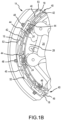
- FIG. 1B illustrates a portion of aircraft wheel braking assembly 10 as viewed into wheel well 18 and wheel well recess 28.
- the various components of aircraft wheel braking assembly 10 may be subjected to the application of compositions and methods for protecting the components from oxidation.
- Brake disks e.g., interleaved rotors 32 and stators 34
- Rotors 32 are secured to torque bars 24 for rotation with wheel 14, while stators 34 are engaged with torque take-out assembly 22.
- At least one actuator 30 is operable to compress interleaved rotors 32 and stators 34 for stopping the aircraft.
- actuator 30 is shown as a hydraulically actuated piston, but many types of actuators are suitable, such as an electromechanical actuator.
- Pressure plate 36 and end plate 38 are disposed at opposite ends of the interleaved rotors 32 and stators 34.
- Rotors 32 and stators 34 can comprise any material suitable for friction disks, including ceramics or carbon materials, such as a carbon/carbon composite.
- Torque take-out assembly 22 is secured to a stationary portion of the landing gear truck such as a bogie beam or other landing gear strut, such that torque take-out assembly 22 and stators 34 are prevented from rotating during braking of the aircraft.
- Carbon-carbon composites (also referred to herein as composite structures, composite substrates, and carbon-carbon composite structures, interchangeably) in the friction disks may operate as a heat sink to absorb large amounts of kinetic energy converted to heat during slowing of the aircraft.
- Heat shield 40 may reflect thermal energy away from wheel well 18 and back toward rotors 32 and stators 34.
- FIG. 1A a portion of wheel well 18 and torque bar 24 is removed to better illustrate heat shield 40 and heat shield segments 42.
- heat shield 40 is attached to wheel 14 and is concentric with wheel well 18. Individual heat shield segments 42 may be secured in place between wheel well 18 and rotors 32 by respective heat shield carriers 44 fixed to wheel well 18.
- Air gap 46 is defined annularly between heat shield segments 42 and wheel well 18.
- Torque bars 24 and heat shield carriers 44 can be secured to wheel 14 using bolts or other fasteners.
- Torque bar bolts 48 can extend through a hole formed in a flange or other mounting surface on wheel 14.
- Each torque bar 24 can optionally include at least one torque bar pin 50 at an end opposite torque bar bolts 48, such that torque bar pin 50 can be received through wheel web hole 52 in web 20.
- Heat shield segments 42 and respective heat shield carriers 44 can then be fastened to wheel well 18 by heat shield fasteners 53.
- carbon-carbon composites may be prone to material loss from oxidation of the carbon.
- various carbon-carbon composite components of aircraft wheel braking assembly 10 may experience both catalytic oxidation and inherent thermal oxidation caused by heating the composite during operation.
- composite rotors 32 and stators 34 may be heated to sufficiently high temperatures that may oxidize the carbon surfaces exposed to air. At elevated temperatures, infiltration of air and contaminants may cause internal oxidation and weakening, especially in and around rotor lugs 54 or stator slots 56 securing the friction disks to the respective torque bar 24 and torque take-out assembly 22.
- carbon-carbon composite components of aircraft wheel braking assembly 10 may retain heat for a substantial time period after slowing the aircraft, oxygen from the ambient atmosphere may react with the carbon matrix and/or carbon fibers to accelerate material loss. Further, damage to brake components may be caused by the oxidation enlargement of cracks around fibers or enlargement of cracks in a reaction-formed porous barrier coating (e.g., a silicon-based barrier coating) applied to the carbon-carbon composite.
- a reaction-formed porous barrier coating e.g., a silicon-based barrier coating
- Elements identified in severely oxidized regions of carbon-carbon composite brake components include potassium (K) and sodium (Na). These alkali contaminants may come into contact with aircraft brakes as part of cleaning or de-icing materials. Other sources include salt (e.g., NaCl) deposits left from seawater or sea spray. These and other contaminants (e.g., Ca ions, Fe ions, oxides and salts containing Fe ions and/or Ca ions, etc.) can penetrate and leave deposits in the pores of carbon-carbon composite aircraft brakes, including the substrate and any reaction-formed porous barrier coating. When such contamination occurs, the rate of carbon loss by oxidation can be increased by one to two orders of magnitude.
- K potassium
- Na sodium
- components of aircraft wheel braking assembly 10 may reach operating temperatures in the range from about 100°C (212°F) up to about 900°C (1652°F), or higher (e.g., 1093°C (2000°F) on a wear or friction surface of a brake disk).
- oxidation protection systems compositions and methods of the present disclosure may be readily adapted to many parts in this and other braking assemblies, as well as to other carbon-carbon composite structures susceptible to oxidation losses from infiltration of atmospheric oxygen and/or catalytic contaminants.
- a method for limiting an oxidation reaction in a substrate may comprise forming an oxidation protection system on the composite structure.
- Forming the oxidation protection system may comprise forming a ceramic layer slurry by combining aluminum and silicon carbide in a solution (a "sol"), applying the ceramic layer slurry to a composite structure, and heating the composite structure to a temperature sufficient to form a ceramic layer on the composite structure.
- Heating the ceramic layer may include exposing the composite structure and ceramic layer slurry to an inert gas, for example, heating the composite structure in the presence of nitrogen gas or argon gas.
- forming the oxidation protection system may further comprise applying a boron slurry, comprising a boron powder in a carrier fluid (such as, for example, water or alcohol), to the composite structure and heating the composite structure to a temperature sufficient to form a boron layer over the composite structure, prior to applying the ceramic layer slurry.
- a pretreatment composition also referred to herein as a pretreatment layer
- forming the oxidation protection system may further comprise forming a sealing composition (also referred to herein as a sealing layer), comprising a sealing glass composition (in the form of a glass frit, powder, or other suitable pulverized form) in a carrier fluid (such as, for example, water), applying the sealing slurry to a composite structure, and heating the composite structure to a temperature sufficient to dry the carrier fluid and form a sealing coating on the ceramic layer.
- a sealing composition also referred to herein as a sealing layer
- a sealing glass composition in the form of a glass frit, powder, or other suitable pulverized form
- a carrier fluid such as, for example, water
- the sealing slurry may comprise a sealing pre-slurry composition including additives, such as, for example, ammonium dihydrogen phosphate and/or aluminum orthophosphate, among others, to improve hydrolytic stability and/or to increase the composite structure's resistance to oxidation, thereby tending to reduce mass loss of composite structure.
- additives such as, for example, ammonium dihydrogen phosphate and/or aluminum orthophosphate, among others, to improve hydrolytic stability and/or to increase the composite structure's resistance to oxidation, thereby tending to reduce mass loss of composite structure.
- Method 200 may, for example, comprise forming an oxidation protection system on non-wearing surfaces of carbon-carbon composite brake components, such as non-wear surfaces 45 and/or rotor lugs 54.
- Non-wear surfaces e.g., non-wear surface 45, as labeled in FIG.
- non-wear surfaces on a brake disk simply reference an exemplary non-wear surface on a brake disk (i.e., a non-friction surface that does not contribute to brake function by having friction with another component, such as another brake disk), but non-wear surfaces similar to non-wear surface 45 may be present on any brake disks (e.g., rotors 32, stators 34, pressure plate 36, end plate 38, or the like).
- method 200 may be used on the back face of pressure plate 36 and/or end plate 38, an inner diameter (ID) surface of stators 34 including stator slots 56, as well as outer diameter (OD) surfaces of rotors 32 including lugs 54.
- ID inner diameter
- OD outer diameter
- the oxidation inhibiting composition of method 200 may be applied to preselected regions of a carbon-carbon composite structure that may be otherwise susceptible to oxidation.
- aircraft brake disks may have the oxidation inhibiting composition applied on or proximate stator slots 56, rotor lugs 54, and/or non-wear surface 45.
- method 200 may comprise forming a ceramic layer slurry (step 210).
- the ceramic layer slurry may comprise aluminum and silicon carbide (SiC).
- the aluminum and silicon carbide may be in powder form.
- the aluminum and silicon carbide may be added to a solution or carrier fluid.
- the solution or carrier fluid may comprise any suitable fluid, such as water, methyltrimethoxysilane ("MTMS"), hexane, cyclohexane, polyvinyl alcohol (PVA), isopropyl alcohol (or other alcohol), any combination of the foregoing, and/or the like.
- MTMS methyltrimethoxysilane
- PVA polyvinyl alcohol
- isopropyl alcohol (or other alcohol) any combination of the foregoing, and/or the like.
- the aluminum powder and silicon carbide powder is added to a sol comprised of MTMS and water.
- the ceramic layer slurry may be formed by mixing MTMS and water to form a sol.
- the sol may comprise between 1% and 50% by weight MTMS, between 10% and 35% by weight MTMS, between 20% and 30% by weight MTMS, or about 25% by weight MTMS.
- the sol may comprise between 50% and 99% by weight water, between 65% and 90% by weight water, between 70% and 80% by weight water, or about 75% by weight water.
- the aluminum powder and silicon carbide powder may be mixed into the sol via any suitable method, such as stirring, tumbling, or ball milling. The aluminum powder and silicon carbide powder may be mixed into the sol for any suitable duration.
- such mixing may take place for under an hour, over an hour, or for multiple hours, between two and ten hours.
- the aluminum powder and silicon carbide powder may be mixed into the sol for between two and four hours, for about two hours, or about three hours (the term "about” as used in this context means plus or minus 30 minutes).
- the aluminum and silicon carbide powders may form between 15% and 80% by weight of the ceramic layer slurry, between 30% and 70% by weight of the ceramic layer slurry, between 40% and 60% by weight of the ceramic layer slurry, or between 40% and 50% by weight of the ceramic layer slurry, with the sol (i.e., the carrier fluid(s)) forming the remaining weight percentage of the ceramic layer slurry.
- the Al-SiC solids may form about 40% or about 45% by weight of the ceramic layer slurry, with the sol (i.e., carrier fluid(s)) forming the remaining weight percentage of the ceramic layer slurry (the term "about” in this context means plus or minus 5 weight percent).
- the ceramic layer slurry may comprise between 0% and 20% by weight aluminum powder, between 1% and 10% by weight aluminum powder, between 1% and 5% by weight aluminum powder, or about 3% by weight aluminum powder (the term “about” in this context means plus or minus 1 weight percent). In various embodiments, the ceramic layer slurry may comprise between 0% and 60% by weight silicon carbide powder, between 10% and 50% by weight silicon carbide powder, between 25% and 40% by weight silicon carbide powder, or about 35% by weight silicon carbide powder (the term "about” in this context means plus or minus 1 weight percent).
- the ceramic layer slurry may further comprise a binder (but in further embodiments, the ceramic layer slurry may not comprise a binder).
- the binder may comprise any suitable compound, such as silicon oxycarbide, silicon oxycarbide generating sol, silicon oxycarbide pre-ceramic polymer, and/or polyvinyl alcohol.
- the binder may comprise between 0.2% and 15% by weight of the ceramic layer slurry, between 5% and 15% by weight of the ceramic layer slurry, or about 10% or about 12% by weight of the ceramic layer slurry (the term "about" in this context means plus or minus 5 weight percent).
- method 200 further comprises applying the ceramic layer slurry to a composite structure (step 220).
- Applying the ceramic layer slurry may comprise, for example, spraying or brushing the ceramic layer slurry to an outer surface of the composite structure (e.g., a non-wear or non-friction surface) or dipping the outer surface of the composite structure in the ceramic layer slurry.
- any suitable manner of applying the ceramic layer slurry to the composite structure is within the scope of the present disclosure.
- the composite structure may refer to a carbon-carbon composite structure.
- method 200 may further comprise a step of heating the composite structure to form a ceramic layer (step 230).
- the composite structure may be heated (e.g., dried or baked) at a temperature in the range from about 500°C (932°F) to about 1500°C (2732°F).
- the composite structure may be heated to a temperature in a range from about 650°C (1202°F) to about 1350°C (2462°F), or between about 800°C (1472°F) to about 1100°C (2012°F).
- the composite structure may be heated to, or at least to, about 900°C (1652°F) (the term "about” in this context means plus or minus 100°C (212°F)).
- Step 230 may, for example, comprise heating the composite structure for a period between about 0.5 hour and about eight hours, or about three hours or about four hours (the term "about” in this context means plus or minus one hour).
- the temperature rise may be controlled at a rate that removes water without boiling and provides temperature uniformity throughout the composite structure.
- the pressure during heating of the substrate may be atmospheric pressure, or between 5 pascals and 150,000 pascals, or between 50 and 100,000 pascals, or between 100 and 50,000 pascals.
- step 230 may be performed in an environment comprising an inert gas, such as, for example, nitrogen or argon.
- an inert gas such as, for example, nitrogen or argon.
- the sol is converted to silicon oxycarbide (SiOC).
- the silicon oxycarbide reacts with the aluminum powder to form aluminum oxide (Al 2 O 3 ) (also referred to as alumina) and additional silicon carbide (SiC).
- Al 2 O 3 also referred to as alumina
- SiC silicon carbide
- the ceramic layer formed from method 200 may comprise between 0% and 20% by weight alumina, or between 1% and 15% by weight alumina, or about 5% by weight alumina, or about 10% by weight alumina (the term “about” in this context means plus or minus 2 weight percent). In various embodiments, the ceramic layer formed from method 200 may comprise between 10% and 90% by weight silicon carbide, between 50% and 80% by weight silicon carbide, between 65% and 75% by weight silicon carbide, or about 70% by weight silicon carbide (the term "about” in this context means plus or minus 5 weight percent).
- the ceramic layer formed from method 200 may comprise between 1% and 50% by weight silicon oxycarbide, between 5% and 40% by weight silicon oxycarbide, between 10% and 30% by weight silicon oxycarbide, or about 20% by weight silicon oxycarbide (the term "about” in this context means plus or minus 5 weight percent).
- a method 300 may further comprise applying a boron slurry to the composite structure (step 306) prior to applying the ceramic layer slurry.
- the boron slurry may comprise a boron compound comprising boron, such as boron, boron carbide, boron nitride, titanium boride, and a carrier fluid (e.g., water, isopropyl alcohol or another alcohol, hexanes, cyclohexane, and/or the like).
- the boron carbide may comprise a powder comprising granules having sizes ranging from 0.4 micrometer (1.575 ⁇ 10 -5 inch) to 100 micrometers (3.94 ⁇ 10 -3 inch) in size.
- the boron slurry may comprise between 10% and 60% by weight boron compound (e.g., boron carbide), and the remainder comprising solvent and/or carrier fluid.
- the boron slurry may further comprise a dispersant, which may be any suitable dispersant.
- the dispersant may comprise aluminum oxide (for example, NanoBYK-3600 ® , sold by BYK Additives & Instruments).
- the boron slurry may comprise less than 1% by weight dispersant.
- step 306 The boron slurry may be applied to the composite structure in step 306 in any suitable manner (spraying, brushing, etc.) and then dried (step 308) to form a boron layer over the composite structure prior to applying the ceramic layer slurry.
- step 308 may comprise heating the composite structure to a temperature sufficient to remove the carrier fluid.
- the composite structure may be heated to a temperature between about 100°C (212°F) and 200°C (392°F), and further, between 100°C (212°F) and 150°C (302°F).
- the ceramic layer slurry may be applied to the boron layer.
- the boron compound from the boron layer e.g., boron carbide
- the ceramic layer resulting from step 230 may comprise aluminum boro-carbide.
- the ceramic layer may at least partially comprise the boron compound layer, or there may be overlap between the ceramic layer and the boron compound layer.
- a method 400 may further comprise applying a pretreating composition (step 404) prior to applying the ceramic layer slurry (prior to step 220) and/or prior to applying the boron slurry (prior to step 306).
- Step 404 may, for example, comprise applying a first pretreating composition to an outer surface of a composite structure, such as a component of aircraft wheel braking assembly 10.
- the first pretreating composition comprises an aluminum oxide (e.g., alumina) in water.
- the aluminum oxide may comprise an additive, such as a nanoparticle dispersion of aluminum oxide (for example, NanoBYK-3600 ® , sold by BYK Additives & Instruments).
- the first pretreating composition may further comprise a surfactant or a wetting agent.
- the composite structure may be porous, allowing the pretreating composition to penetrate at least a portion of the pores of the composite structure.
- the component may be heated to remove water and fix the aluminum oxide in place (step 408).
- the component may be heated between about 100°C (212°F) and 200°C (392°F), and further, between 100°C (212°F) and 150°C (302°F).
- an aluminum phosphate layer (also referred to herein as a second pretreating composition), as discussed herein, may be formed over the alumina layer (e.g., between the alumina layer and the ceramic layer, or between the alumina layer and the boron layer, in accordance with various embodiments) at step 406, as illustrated in FIG. 3A herein.
- the aluminum phosphate layer may additionally or alternatively be applied between the ceramic layer (i.e., after steps 210-230) and the glass layer (i.e., before steps 540-550), as illustrated in FIG. 3B herein.
- method 400 may further comprise applying an aluminum phosphate pre-slurry to the composite structure (e.g., over the alumina layer and/or over the ceramic layer) (step 406).
- the aluminum phosphate pre-slurry comprises ammonium dihydrogen phosphate ("ADHP") with a carrier fluid (e.g., water).
- the aluminum phosphate pre-slurry comprises aluminum orthophosphate with a carrier fluid (e.g., water).
- the aluminum phosphate pre-slurry comprises aluminum phosphate with a carrier fluid (e.g., water).
- the aluminum phosphate pre-slurry comprises phosphoric acid mixed together with aluminum hydroxide and/or aluminum oxide, with a carrier fluid (e.g., water).
- alumina and aluminum phosphate are applied to the composite structure as a base line, followed by the ceramic layer (i.e., steps 210 through step 230), and then the glass sealing slurry (i.e., steps 540 through step 550 of FIG. 2D ).
- alumina and aluminum phosphate are applied to the composite structure as a base line, followed by the boron layer (e.g., step 306 and step 308) followed by the ceramic layer (i.e., steps 210 through step 230), and then the glass sealing slurry (i.e., steps 540 through step 550 of FIG. 2D ).
- the second pretreating composition may further comprise, for example, a second metal salt such as a magnesium salt.
- a second metal salt such as a magnesium salt.
- the aluminum to phosphorus molar ratio of the aluminum phosphate is 1 to 3 or less.
- the second pretreating composition may also comprise a surfactant or a wetting agent.
- the second pretreating composition is applied to the composite structure atop the first pretreating composition.
- the component may be heated to remove water and fix the aluminum phosphate in place (step 408).
- the component may be heated between about 600°C (1112°F) and about 800°C (1472°F), and further, between about 650°C (1202°F) and 750°C (1382°F).
- method 400 further comprises applying a boron slurry to the composite structure (step 306) prior to applying the ceramic layer slurry, and drying the composite structure (step 308) to form a boron layer over the composite structure (e.g., between the pretreating composition and the ceramic layer), as described above with respect to FIG. 2B .
- method 400 further comprises forming a ceramic layer slurry (step 210), applying the ceramic layer slurry to the composite structure (step 220), and heating the composite structure to form a ceramic layer (step 230), as described above with respect to FIG. 2A .
- a method 500 which comprises steps also found in method 200, method 300, and method 400, may further comprise a step 540, of forming a sealing slurry by combining a sealing pre-slurry composition, which may comprise a sealing glass composition in glass frit or powder form, with a carrier fluid (such as, for example, water).
- the sealing slurry may be applied to the composite structure (step 545), for example, by spraying or brushing the sealing slurry on to an outer surface of the ceramic layer. Any suitable manner of applying the sealing slurry to the ceramic layer and/or composite structure is within the scope of the present disclosure (e.g., the application methods described in relation to step 220).
- the sealing slurry may be substantially free of boron nitride. In this case, “substantially free” means less than 0.01 percent by weight.
- the sealing slurry is applied on top of the ceramic layer (i.e., steps 210 through step 230 are performed before steps 540 through step 550).
- the sealing slurry is applied on top of the aluminum phosphate layer (i.e., step 406 and step 408 are performed after steps 210 through step 230 and before steps 540 through step 550).
- step 406 and step 408 may alternatively be performed between step 404 and step 306 (see FIG. 2C ).
- the sealing slurry may be applied directly on top of the ceramic layer, in accordance with various embodiments.
- the sealing glass composition may comprise phosphate glass in the form of a glass frit, powder, or other suitable pulverized and/or ground form, with a carrier fluid (such as, for example, water).
- the sealing glass composition may comprise and/or be combined with one or more alkali metal glass modifiers, one or more glass network modifiers and/or one or more additional glass formers.
- boron oxide or a precursor may optionally be combined with the P 2 O 5 mixture to form a borophosphate glass, which has improved self-healing properties at the operating temperatures typically seen in aircraft braking assemblies.
- the phosphate glass and/or borophosphate glass may be characterized by the absence of an oxide of silicon. Further, the ratio of P 2 O 5 to metal oxide in the fused glass may be in the range from about 0.25 to about 5 by weight.
- Potential alkali metal glass modifiers may be selected from oxides of lithium, sodium, potassium, rubidium, cesium, and mixtures thereof.
- the glass modifier may be an oxide of lithium, sodium, potassium, or mixtures thereof.
- These or other glass modifiers may function as fluxing agents.
- Additional glass formers can include oxides of boron, silicon, sulfur, germanium, arsenic, antimony, and mixtures thereof.
- Suitable glass network modifiers include oxides of vanadium, aluminum, tin, titanium, chromium, manganese, iron, cobalt, nickel, copper, mercury, zinc, thulium, lead, zirconium, lanthanum, cerium, praseodymium, neodymium, samarium, europium, gadolinium, terbium, dysprosium, holmium, erbium, thulium, ytterbium, actinium, thorium, uranium, yttrium, gallium, magnesium, calcium, strontium, barium, tin, bismuth, cadmium, and mixtures thereof.
- the sealing glass composition may be prepared by combining the above ingredients and heating them to a fusion temperature.
- the fusion temperature may be in the range from about 700° C (1292°F) to about 1500° C (2732°F).
- the resultant melt may then be cooled and pulverized and/or ground to form a glass frit or powder.
- the sealing glass composition may be annealed to a rigid, friable state prior to being pulverized. Glass transition temperature (T g ), glass softening temperature (T s ) and glass melting temperature (T m ) may be increased by increasing refinement time and/or temperature.
- the sealing glass composition comprises from about 20 mol% to about 80 mol% of P 2 O 5 . In various embodiments, the sealing glass composition comprises from about 30 mol% to about 70 mol% P 2 O 5 , or precursor thereof. In various embodiments, the sealing glass composition comprises from about 40 to about 60 mol% of P 2 O 5 . In this context, the term "about” means plus or minus 5 mol%.
- the sealing glass composition may comprise, or be combined with, from about 5 mol% to about 50 mol% of the alkali metal oxide. In various embodiments, the sealing glass composition may comprise, or be combined with, from about 10 mol% to about 40 mol% of the alkali metal oxide. Further, the sealing glass composition may comprise, or be combined with, from about 15 to about 30 mol% of the alkali metal oxide or one or more precursors thereof. In various embodiments, the sealing glass composition may comprise, or be combined with, from about 0.5 mol% to about 50 mol% of one or more of the above-indicated glass formers. The sealing glass composition may comprise, or be combined with, about 5 to about 20 mol% of one or more of the above-indicated glass formers. As used herein, mol% is defined as the number of moles of a constituent per the total moles of the solution.
- the sealing glass composition may comprise, or be combined with, from about 0.5 mol% to about 40 mol% of one or more of the above-indicated glass network modifiers.
- the sealing glass composition may comprise, or be combined with, from about 2.0 mol% to about 25 mol% of one or more of the above-indicated glass network modifiers.
- the sealing glass composition may be represented by the formula: a(A' 2 O) x (P 2 O 5 ) y1 b(G f O) y2 c(A"O) z [1]
- A' is selected from: lithium, sodium, potassium, rubidium, cesium, and mixtures thereof;
- G f is selected from: boron, silicon, sulfur, germanium, arsenic, antimony, bismuth, and mixtures thereof;
- the sealing slurry may comprise any suitable weight percentage sealing glass composition.
- the sealing slurry may comprise between 20% and 50% by weight sealing glass composition, between 20% and 40% by weight sealing glass composition, between 20% and 30% by weight sealing glass composition, and/or between 30% and 40% by weight sealing glass composition.
- the sealing pre-slurry composition (and/or the resulting sealing layer, discussed in association with step 550) may comprise any suitable weight percentage sealing glass composition.
- the sealing pre-slurry composition may comprise between 50% and 95% by weight sealing glass composition, between 60% and 90% by weight sealing glass composition, and/or between 70% and 80% by weight sealing glass composition.
- method 500 may further comprise a step 550 of heating the composite structure to form a sealing layer comprising glass over the ceramic layer (or over the aluminum phosphate layer in accordance with various embodiments).
- the composite structure may be heated (e.g., dried or baked) at a temperature in the range from about 200°C (292°F) to about 1000°C (1832°F).
- the composite structure is heated to a temperature in a range from about 600°C (1112°F) to about 1000° C (1832°F), or between about 200°C (292°F) to about 900°C (1652°F), or further, between about 400° C (752°F) to about 850°C (1562°F).
- Step 550 may, for example, comprise heating the composite structure for a period between about 0.5 hour and about 8 hours, wherein the term "about” in this context only means plus or minus 0.25 hours.
- the sealing layer may also be referred to as a coating.
- the composite structure may be heated to a first, lower temperature (for example, about 30°C (86°F) to about 400°C (752°F)) to bake or dry the sealing layer at a controlled depth.
- a second, higher temperature for example, about 300°C (572°F) to about 1000°C (1832°F)
- the duration of each heating step can be determined as a fraction of the overall heating time and can range from about 10% to about 50%, wherein the term "about" in this context only means plus or minus 5%.
- the duration of the lower temperature heating step(s) can range from about 20% to about 40% of the overall heating time, wherein the term "about” in this context only means plus or minus 5%.
- the lower temperature step(s) may occupy a larger fraction of the overall heating time, for example, to provide relatively slow heating up to and through the first lower temperature.
- the exact heating profile will depend on a combination of the first temperature and desired depth of the drying portion.
- Step 550 may be performed in an inert environment, such as under a blanket of inert gas or less reactive gas (e.g., nitrogen, argon, other noble gases, and the like).
- a composite structure may be pretreated or warmed prior to application of the sealing slurry to aid in the penetration of the sealing slurry.
- Step 250 may be for a period of about 2 hours at a temperature of about 600°C (1112°F) to about 900°C (1652°F), wherein the term "about” in this context only means plus or minus 50°C.
- the composite structure and the sealing slurry may then be dried or baked in a non-oxidizing, inert or less reactive atmosphere, e.g., noble gasses and/or nitrogen (N 2 ), to optimize the retention of the sealing pre-slurry composition of the sealing slurry and resulting sealing layer filling any pores or cracks in the ceramic layer.
- This retention may, for example, be improved by heating the composite structure to about 200°C (392°F) and maintaining the temperature for about 1 hour before heating the carbon-carbon composite to a temperature in the range described above.
- the temperature rise may be controlled at a rate that removes water without boiling and provides temperature uniformity throughout the composite structure.
- the ceramic layer may crack, which causes a risk of oxygen penetrating through the oxidation protection system and allowing oxidation of the composite structure.
- the sealing layer may melt and/or flow, allowing the sealing layer to fill any cracks that may form in the ceramic layer, thus, sealing the ceramic layer and the oxidation protection system.
- the sealing slurry may comprise an additional metal salt.
- the cation of the additional metal salt may be multivalent.
- the metal may be an alkaline earth metal or a transition metal. In various embodiments, the metal may be an alkali metal.
- the multivalent cation may be derived from a non-metallic element such as boron.
- the term "metal" is used herein to include multivalent elements such as boron that are technically non-metallic.
- the metal of the additional metal salt may be an alkaline earth metal such as calcium, magnesium, strontium, barium, or a mixture of two or more thereof.
- the metal for the additional metal salt may be iron, manganese, tin, zinc, or a mixture of two or more thereof.
- the anion for the additional metal salt may be an inorganic anion such as a phosphate, halide, sulfate or nitrate, or an organic anion such as acetate.
- the additional metal salt may be an alkaline earth metal salt such as an alkaline earth metal phosphate.
- the additional metal salt may be a magnesium salt such as magnesium phosphate.
- the additional metal salt may be an alkaline earth metal nitrate, an alkaline earth metal halide, an alkaline earth metal sulfate, an alkaline earth metal acetate, or a mixture of two or more thereof.
- the additional metal salt may be magnesium nitrate, magnesium halide, magnesium sulfate, or a mixture of two or more thereof.
- the additional metal salt may comprise: (i) magnesium phosphate; and (ii) a magnesium nitrate, magnesium halide, magnesium sulfate, or a mixture of two or more thereof.
- the additional metal salt may be selected with reference to its compatibility with other ingredients in the sealing slurry.
- Compatibility may include metal phosphates that do not precipitate, flocculate, agglomerate, react to form undesirable species, or settle out prior to application of the sealing slurry to the carbon-carbon composite.
- the phosphates may be monobasic (H 2 PO 4 - ), dibasic (HPO 4 -2 ), or tribasic (PO 4 -3 ).
- the phosphates may be hydrated.
- alkaline earth metal phosphates examples include calcium hydrogen phosphate (calcium phosphate, dibasic), calcium phosphate tribasic octahydrate, magnesium hydrogen phosphate (magnesium phosphate, dibasic), magnesium phosphate tribasic octahydrate, strontium hydrogen phosphate (strontium phosphate, dibasic), strontium phosphate tribasic octahydrate and barium phosphate.
- a chemical equivalent of the additional metal salt may be used as the additional metal salt.
- Chemical equivalents include compounds that yield an equivalent (in this instance, an equivalent of the additional metal salt) in response to an outside stimulus such as, temperature, hydration, or dehydration.
- equivalents of alkaline earth metal phosphates may include alkaline earth metal pyrophosphates, hypophosphates, hypophosphites and orthophosphites.
- Equivalent compounds include magnesium and barium pyrophosphate, magnesium and barium orthophosphate, magnesium and barium hypophosphate, magnesium and barium hypophosphite, and magnesium and barium orthophosphite.
- the addition of multivalent cations, such as alkaline earth metals, transition metals and nonmetallic elements such as boron, to the sealing slurry enhances the hydrolytic stability of the metal-phosphate network.
- the hydrolytic stability of the metal-phosphate network increases as the metal content increases, however a change from one metallic element to another may influence oxidation inhibition to a greater extent than a variation in the metal-phosphate ratio.
- the solubility of the phosphate compounds may be influenced by the nature of the cation associated with the phosphate anion.
- phosphates incorporating monovalent cations such as sodium orthophosphate or phosphoric acid (hydrogen cations) are very soluble in water, while (tri)barium orthophosphate is insoluble.
- Phosphoric acids can be condensed to form networks but such compounds tend to remain hydrolytically unstable.
- the multivalent cations link phosphate anions creating a phosphate network with reduced solubility.
- Another factor that may influence hydrolytic stability is the presence of - P-O-H groups in the condensed phosphate product formed from the sealing slurry during thermal treatment.
- the sealing slurry may be formulated to minimize concentration of these species and any subsequent hydrolytic instability. Whereas increasing the metal content may enhance the hydrolytic stability of the sealing slurry, it may be desirable to strike a balance between composition stability and effectiveness as an oxidation inhibitor.
- the additional metal salt may be present in the sealing slurry at a concentration in the range from about 0.5 weight percent to about 30 weight percent, and in various embodiments from about 0.5 weight percent to about 25 weight percent, and in various embodiments from about 5 weight percent to about 20 weight percent.
- a combination of two or more additional metal salts may be present at a concentration in the range from about 10 weight percent to about 30 weight percent, and in various embodiments from about 12 weight percent to about 20 weight percent.
- FIG. 3A depicts a substrate 605 (e.g., a composite structure) with an oxidation protection system 650 disposed thereon (e.g., on a non-wear or non-friction surface).
- the oxidation protection system 650 may comprise a ceramic layer 630.
- ceramic layer 630 is formed as discussed with respect to steps 210-230 of FIG. 2A through FIG. 2D herein.
- oxidation protection system 650 may comprise one or more layer(s) between the substrate 605 and the ceramic layer 630, for example, a first pretreatment layer 610, a second pretreatment layer 615, and/or a boron (e.g., boron carbide) layer 620, as discussed herein.
- Pretreatment layer 610 may be an alumina layer as discussed with respect to step 404 of FIG. 2C and FIG. 2D herein.
- Pretreatment layer 615 may be an aluminum phosphate layer as discussed with respect to step 406 and step 408 of FIG. 2C .
- Boron layer 620 may be formed as discussed with respect to step 306 and step 308 of FIG. 2B , FIG. 2C , and FIG. 2D herein.
- phosphate layer 615 is disposed between the first pretreatment layer 610 and the boron layer 620, though boron layer 620 may be omitted and the phosphate layer 615 may be between and in direct contact with the pretreatment layer 610 and the ceramic layer 630.
- oxidation protection system 650 may comprise a sealing layer 640.
- Sealing layer 640 may be a glass sealing layer as discussed with respect to steps 540-550 of FIG. 2D herein.
- the sealing layer 640 may be disposed on, and directly contact, the ceramic layer 630, such that the ceramic layer 630 is disposed between the sealing layer 640 and the substrate 605.
- the sealing layer 640 may be disposed on, and directly contact, the aluminum phosphate layer 615.
- a substrate 605 e.g., a composite structure
- an oxidation protection system 651 disposed thereon (e.g., on a non-wear or non-friction surface).
- Oxidation protection system 651 may be similar to oxidation protection system 650, except that the second pretreatment layer 615 (e.g., aluminum phosphate) of oxidation protection system 651 is disposed between ceramic layer 630 and sealing layer 640.
- first pretreatment layer 610 is disposed between the substrate 605 and the boron layer 620, though boron layer 620 may be omitted and the first pretreatment layer 610 may be between and in direct contact with the ceramic layer 630.
- TABLE 1 illustrates an exemplary sealing slurry prepared in accordance with the embodiments discussed herein. Each numerical value in TABLE 1 is the number of grams of the particular substance added to the slurry.
- TABLE 1 Example >> Sealing Pre-Slurry Composition (Slurry A) Glass frit 34 Aluminum orthophosphate (o-AlPO 4 ) 2.27 Aluminum Phosphate Pre-Slurry Composition (Slurry B) H 2 O 52.4 Ammonium dihydrogen phosphate (ADHP) 11.33
- an oxidation protection system sealing slurry comprises a pre-slurry composition, comprising glass frit and various additives such as aluminum orthophosphate in a carrier fluid (i.e., water), was prepared.
- a carrier fluid i.e., water
- an oxidation protection system aluminum phosphate slurry (slurry B) comprises ammonium dihydrogen phosphate in a carrier fluid.
- Slurry A may be a suitable sealing slurry which will serve as a sealing layer after heating (such as during step 550).
- Slurry A may be substantially free of boron nitride. In this case, "substantially free" means less than 0.01 percent by weight.
- plot 700 in FIG. 4 may allow evaluation of oxidation protection systems comprising a ceramic layer and a sealing layer versus oxidation protection systems comprising a sealing layer without a ceramic layer.
- Data set 702 represents an oxidation protection system comprising a ceramic layer and a sealing layer
- data set 704 represents an oxidation protection system comprising a sealing layer (resulting from slurry A) without a ceramic layer.
- Percent weight loss is shown on the y-axis and exposure time is shown on the x-axis of the graph depicted in FIG. 4 .
- the oxidation protection system represented by data set 704 was prepared by applying slurry A to carbon-carbon composite coupons and heated to form a sealing slurry, in accordance with embodiments discussed herein.
- Slurry A for data set 704 is not hydrated (i.e., dry).
- Example 1 represented by data set 702, was prepared by: (1) applying a boron slurry comprising 14 grams of boron carbide, 86 grams of water, and 0.2 grams of dispersant to a carbon-carbon composite coupon, by dipping the coupon in the boron compound slurry; (2) air-drying the boron compound slurry to form a boron layer on the coupon; (3) preparing a ceramic layer slurry comprising 17.02 grams of MTMS, 49.53 grams of water, 30.06 grams of 0.7 ⁇ m silicon carbide powder, and 3.10 grams of 3-5-micron aluminum powder; (4) applying the ceramic layer slurry to the boron layer by dipping the coupon in the ceramic layer slurry; (5) air-drying the ceramic layer slurry; (6) heating the coupon at 950°C (1742°F) for about one hour under an environment comprising nitrogen gas to form the ceramic layer; (7) applying slurry A to the ceramic layer; and (8) heating the coupon at 870°C (1598°F) to melt the
- the oxidation protection system having the ceramic layer and the sealing layer resulted in drastically less weight loss of the composite structure than the oxidation protection systems having a sealing layer with no ceramic layer (data set 704). That is, the oxidation protection system having the ceramic layer and the sealing layer (data set 702) resulted in about 0.5% weight loss of the substrate at 1250 °F (677 °C) at the end of the test, while the oxidation protection system having a sealing layer with no ceramic layer (data set 704) resulted in about 1% weight loss.
- oxidation protection systems having the ceramic layer and the sealing layer (data set 702) provided significantly greater oxidation protection than the oxidation protection system having the sealing layer only (data set 704).
- the oxidation protection systems comprising the ceramic layer (comprising alumina, silicon carbide, silicon oxycarbide, and/or aluminum boron carbide), along with the sealing layer disposed thereon, creates a strong barrier which stops oxygen from passing therethrough and causing oxidation of the underlying substrate (especially at elevated temperatures of 1250 °F).
- the economical preparation and application of the involved slurries along with the positive and improved oxidation protection results indicate that the systems and methods discussed herein provide effective oxidation protection, in accordance with various embodiments.
- references to "one embodiment,” “an embodiment,” “an example embodiment,” etc. indicate that the embodiment described may include a particular feature, structure, or characteristic, but every embodiment may not necessarily include the particular feature, structure, or characteristic. Moreover, such phrases are not necessarily referring to the same embodiment. Further, when a particular feature, structure, or characteristic is described in connection with an embodiment, it is submitted that it is within the knowledge of one skilled in the art to affect such feature, structure, or characteristic in connection with other embodiments whether or not explicitly described. After reading the description, it will be apparent to one skilled in the relevant art(s) how to implement the disclosure in alternative embodiments.
Landscapes
- Chemical & Material Sciences (AREA)
- Engineering & Computer Science (AREA)
- Ceramic Engineering (AREA)
- Materials Engineering (AREA)
- Structural Engineering (AREA)
- Organic Chemistry (AREA)
- General Engineering & Computer Science (AREA)
- Manufacturing & Machinery (AREA)
- Inorganic Chemistry (AREA)
- Mechanical Engineering (AREA)
- Composite Materials (AREA)
- Braking Arrangements (AREA)
Abstract
Description
- The present disclosure relates generally to composites and, more specifically, to oxidation protection systems for carbon-carbon composite structures.
- Oxidation protection systems for carbon-carbon composites are typically designed to minimize loss of carbon material due to oxidation at operating conditions, which include temperatures of 800°C (1472°F) or higher. Layers comprising ceramic materials within an oxidation protection system that are deposited onto a substrate by chemical vapor deposition ("CVD") may provide desirable oxidation protection. However, CVD processes may be expensive and cost-prohibitive.
- A method for forming an oxidation protection system on a composite structure is disclosed, comprising applying a ceramic layer slurry to the composite structure, wherein the ceramic layer slurry comprises aluminum and silicon carbide in a sol, and heating the composite structure to form a ceramic layer on the composite structure, wherein the ceramic layer comprises between 1% and 20% alumina by weight.
- In various embodiments, the sol comprises methyltrimethoxysilane and water.
- In various embodiments, the method further comprises applying a sealing slurry to the composite structure, wherein the sealing slurry comprises a sealing pre-slurry composition and a sealing carrier fluid, wherein the sealing pre-slurry composition comprises a sealing glass composition, and heating the composite structure to form a sealing layer on the ceramic layer.
- In various embodiments, the sealing glass composition is represented by a formula a(A'2O)x(P2O5)y1b(GfO)y2c(A"O)z. A' is selected from: lithium, sodium, potassium, rubidium, cesium, and mixtures thereof. Gf is selected from: boron, silicon, sulfur, germanium, arsenic, antimony, and mixtures thereof. A" is selected from: vanadium, aluminum, tin, titanium, chromium, manganese, iron, cobalt, nickel, copper, mercury, zinc, thulium, lead, zirconium, lanthanum, cerium, praseodymium, neodymium, samarium, europium, gadolinium, terbium, dysprosium, holmium, erbium, thulium, ytterbium, actinium, thorium, uranium, yttrium, gallium, magnesium, calcium, strontium, barium, tin, bismuth, cadmium, and mixtures thereof. a is a number in a range from 1 to about 5. b is a number in a range from 0 to about 10. c is a number in a range from 0 to about 30. x is a number in a range from about 0.050 to about 0.500. yi is a number in a range from about 0.100 to about 0.950. y2 is a number in a range from 0 to about 0.20. z is a number in a range from about 0.01 to about 0.5. (x + y1 + y2 + z)=1. x < (y1 + y2).
- In various embodiments, the method further comprises preparing the ceramic layer slurry by combining methyltrimethoxysilane and water to form the sol and mixing aluminum powder and silicon carbide powder in the sol.
- In various embodiments, the ceramic layer slurry comprises between 1% and 10% by weight aluminum powder.
- In various embodiments, the ceramic layer slurry comprises between 10% and 50% by weight silicon carbide powder.
- In various embodiments, the ceramic layer comprises between 1% and 15% by weight alumina.
- In various embodiments, the ceramic layer comprises between 50% and 80% by weight silicon carbide.
- In various embodiments, the ceramic layer comprises between 10% and 30% by weight silicon oxycarbide.
- In various embodiments, the method further comprises applying a boron slurry to the composite structure prior to the applying the ceramic layer slurry.
- In various embodiments, the method further comprises forming the boron slurry by combining boron carbide and a carrier fluid.
- In various embodiments, the method further comprises applying a pretreating composition to the composite structure prior to applying the boron slurry.
- In various embodiments, applying the pretreating composition to the composite structure comprises applying a first pretreating composition comprising aluminum oxide in water to the composite structure, heating the composite structure to a temperature sufficient remove the water and fix the aluminum oxide in place.
- In various embodiments, applying the pretreating composition to the composite structure further comprises applying a second pretreating composition. In various embodiments, the second pretreating composition comprises phosphoric acid and at least one of aluminum phosphate, aluminum hydroxide, or aluminum oxide. In various embodiments, the second pretreating composition comprises ammonium dihydrogen phosphate. In various embodiments, the second pretreating composition comprises aluminum orthophosphate. In various embodiments, the second pretreating composition comprises aluminum phosphate.
- An oxidation protection system disposed on an outer surface of a substrate is disclosed. In various embodiments, the oxidation protection system comprises a ceramic layer comprising between 1% and 20% by weight alumina, between 50% and 80% silicon carbide, and between 10% and 30% by weight silicon oxycarbide, and a sealing layer comprising a sealing glass composition located over the ceramic layer.
- In various embodiments, the oxidation protection system further comprises a boron layer formed between the ceramic layer and the substrate.
- In various embodiments, the ceramic layer comprises about 5% by weight alumina, about 75% by weight silicon carbide and about 20% by weight silicon oxycarbide.
- An aircraft brake disk is disclosed, comprising a carbon-carbon composite structure comprising a non-friction surface, and an oxidation protection system disposed on the non-friction surface. The oxidation protection system includes a ceramic layer comprising between 1% and 20% by weight alumina, between 50% and 80% silicon carbide, and between 10% and 30% by weight silicon oxycarbide, and a sealing layer comprising a sealing glass composition located over the ceramic layer.
- In various embodiments, the oxidation protection system further comprising a boron layer formed between the ceramic layer and the non-friction surface.
- The foregoing features and elements may be combined in various combinations without exclusivity, unless expressly indicated herein otherwise. These features and elements as well as the operation of the disclosed embodiments will become more apparent in light of the following description and accompanying drawings.
- The subject matter of the present disclosure is particularly pointed out and distinctly claimed in the concluding portion of the specification. A more complete understanding of the present disclosure, however, may best be obtained by referring to the detailed description and claims when considered in connection with the drawing figures, wherein like numerals denote like elements.
-
FIG. 1A illustrates a cross sectional view of an aircraft wheel braking assembly, in accordance with various embodiments; -
FIG. 1B illustrates a partial side view of an aircraft wheel braking assembly, in accordance with various embodiments; -
FIGs. 2A ,2B ,2C , and2D illustrate methods for coating a composite structure, in accordance with various embodiments; -
FIG. 3A and FIG. 3B illustrate substrates comprising an oxidation protection system disposed thereon, in accordance with various embodiments; and -
FIG. 4 illustrates experimental data obtained from testing oxidation protection systems, in accordance with various embodiments. - The detailed description of embodiments herein makes reference to the accompanying drawings, which show embodiments by way of illustration. While these embodiments are described in sufficient detail to enable those skilled in the art to practice the disclosure, it should be understood that other embodiments may be realized and that logical, chemical, and mechanical changes may be made without departing from the scope of the invention as defined by the claims. Thus, the detailed description herein is presented for purposes of illustration only and not for limitation. For example, any reference to singular includes plural embodiments, and any reference to more than one component or step may include a singular embodiment or step. Also, any reference to attached, fixed, connected or the like may include permanent, removable, temporary, partial, full and/or any other possible attachment option. Further, any steps in a method discussed herein may be performed in any suitable order or combination.
- With initial reference to
FIG. 1A and1B , aircraftwheel braking assembly 10 such as may be found on an aircraft, in accordance with various embodiments is illustrated. Aircraft wheel braking assembly may, for example, comprise abogie axle 12, awheel 14 including ahub 16 and awheel well 18, aweb 20, a torque take-outassembly 22, one or more torque bars 24, a wheelrotational axis 26, awheel well recess 28, anactuator 30,multiple brake rotors 32,multiple brake stators 34, apressure plate 36, anend plate 38, aheat shield 40, multipleheat shield segments 42, multipleheat shield carriers 44, anair gap 46, multipletorque bar bolts 48, atorque bar pin 50, awheel web hole 52, multipleheat shield fasteners 53, multiple rotor lugs 54, andmultiple stator slots 56.FIG. 1B illustrates a portion of aircraftwheel braking assembly 10 as viewed into wheel well 18 andwheel well recess 28. - In various embodiments, the various components of aircraft
wheel braking assembly 10 may be subjected to the application of compositions and methods for protecting the components from oxidation. - Brake disks (e.g., interleaved
rotors 32 and stators 34) are disposed inwheel well recess 28 ofwheel well 18.Rotors 32 are secured totorque bars 24 for rotation withwheel 14, whilestators 34 are engaged with torque take-outassembly 22. At least oneactuator 30 is operable to compress interleavedrotors 32 andstators 34 for stopping the aircraft. In this example,actuator 30 is shown as a hydraulically actuated piston, but many types of actuators are suitable, such as an electromechanical actuator.Pressure plate 36 andend plate 38 are disposed at opposite ends of the interleavedrotors 32 andstators 34.Rotors 32 andstators 34 can comprise any material suitable for friction disks, including ceramics or carbon materials, such as a carbon/carbon composite. - Through compression of interleaved
rotors 32 andstators 34 betweenpressure plates 36 andend plate 38, the resulting frictional contact slows rotation ofwheel 14. Torque take-outassembly 22 is secured to a stationary portion of the landing gear truck such as a bogie beam or other landing gear strut, such that torque take-outassembly 22 andstators 34 are prevented from rotating during braking of the aircraft. - Carbon-carbon composites (also referred to herein as composite structures, composite substrates, and carbon-carbon composite structures, interchangeably) in the friction disks may operate as a heat sink to absorb large amounts of kinetic energy converted to heat during slowing of the aircraft.
Heat shield 40 may reflect thermal energy away from wheel well 18 and back towardrotors 32 andstators 34. With reference toFIG. 1A , a portion of wheel well 18 andtorque bar 24 is removed to better illustrateheat shield 40 andheat shield segments 42. With reference toFIG. 1B ,heat shield 40 is attached towheel 14 and is concentric withwheel well 18. Individualheat shield segments 42 may be secured in place between wheel well 18 androtors 32 by respectiveheat shield carriers 44 fixed towheel well 18.Air gap 46 is defined annularly betweenheat shield segments 42 andwheel well 18. - Torque bars 24 and
heat shield carriers 44 can be secured towheel 14 using bolts or other fasteners.Torque bar bolts 48 can extend through a hole formed in a flange or other mounting surface onwheel 14. Eachtorque bar 24 can optionally include at least onetorque bar pin 50 at an end oppositetorque bar bolts 48, such thattorque bar pin 50 can be received throughwheel web hole 52 inweb 20.Heat shield segments 42 and respectiveheat shield carriers 44 can then be fastened to wheel well 18 byheat shield fasteners 53. - Under the operating conditions (e.g., high temperature) of aircraft
wheel braking assembly 10, carbon-carbon composites may be prone to material loss from oxidation of the carbon. For example, various carbon-carbon composite components of aircraftwheel braking assembly 10 may experience both catalytic oxidation and inherent thermal oxidation caused by heating the composite during operation. In various embodiments,composite rotors 32 andstators 34 may be heated to sufficiently high temperatures that may oxidize the carbon surfaces exposed to air. At elevated temperatures, infiltration of air and contaminants may cause internal oxidation and weakening, especially in and around rotor lugs 54 orstator slots 56 securing the friction disks to therespective torque bar 24 and torque take-outassembly 22. Because carbon-carbon composite components of aircraftwheel braking assembly 10 may retain heat for a substantial time period after slowing the aircraft, oxygen from the ambient atmosphere may react with the carbon matrix and/or carbon fibers to accelerate material loss. Further, damage to brake components may be caused by the oxidation enlargement of cracks around fibers or enlargement of cracks in a reaction-formed porous barrier coating (e.g., a silicon-based barrier coating) applied to the carbon-carbon composite. - Elements identified in severely oxidized regions of carbon-carbon composite brake components include potassium (K) and sodium (Na). These alkali contaminants may come into contact with aircraft brakes as part of cleaning or de-icing materials. Other sources include salt (e.g., NaCl) deposits left from seawater or sea spray. These and other contaminants (e.g., Ca ions, Fe ions, oxides and salts containing Fe ions and/or Ca ions, etc.) can penetrate and leave deposits in the pores of carbon-carbon composite aircraft brakes, including the substrate and any reaction-formed porous barrier coating. When such contamination occurs, the rate of carbon loss by oxidation can be increased by one to two orders of magnitude.
- In various embodiments, components of aircraft
wheel braking assembly 10 may reach operating temperatures in the range from about 100°C (212°F) up to about 900°C (1652°F), or higher (e.g., 1093°C (2000°F) on a wear or friction surface of a brake disk). However, it will be recognized that the oxidation protection systems compositions and methods of the present disclosure may be readily adapted to many parts in this and other braking assemblies, as well as to other carbon-carbon composite structures susceptible to oxidation losses from infiltration of atmospheric oxygen and/or catalytic contaminants. - In various embodiments, a method for limiting an oxidation reaction in a substrate (e.g., a composite structure) may comprise forming an oxidation protection system on the composite structure. Forming the oxidation protection system may comprise forming a ceramic layer slurry by combining aluminum and silicon carbide in a solution (a "sol"), applying the ceramic layer slurry to a composite structure, and heating the composite structure to a temperature sufficient to form a ceramic layer on the composite structure. Heating the ceramic layer may include exposing the composite structure and ceramic layer slurry to an inert gas, for example, heating the composite structure in the presence of nitrogen gas or argon gas.
- In various embodiments, forming the oxidation protection system may further comprise applying a boron slurry, comprising a boron powder in a carrier fluid (such as, for example, water or alcohol), to the composite structure and heating the composite structure to a temperature sufficient to form a boron layer over the composite structure, prior to applying the ceramic layer slurry. In various embodiments, forming the oxidation protection system may further comprise applying a pretreatment composition (also referred to herein as a pretreatment layer) to the composite structure prior to applying the ceramic layer and/or the boron slurry. In various embodiments, forming the oxidation protection system may further comprise forming a sealing composition (also referred to herein as a sealing layer), comprising a sealing glass composition (in the form of a glass frit, powder, or other suitable pulverized form) in a carrier fluid (such as, for example, water), applying the sealing slurry to a composite structure, and heating the composite structure to a temperature sufficient to dry the carrier fluid and form a sealing coating on the ceramic layer. In various embodiments, the sealing slurry may comprise a sealing pre-slurry composition including additives, such as, for example, ammonium dihydrogen phosphate and/or aluminum orthophosphate, among others, to improve hydrolytic stability and/or to increase the composite structure's resistance to oxidation, thereby tending to reduce mass loss of composite structure.
- With initial reference to
FIGS. 1A and2A , amethod 200 for forming an oxidation protection system on a composite structure, in accordance with various embodiments, is illustrated.Method 200 may, for example, comprise forming an oxidation protection system on non-wearing surfaces of carbon-carbon composite brake components, such asnon-wear surfaces 45 and/or rotor lugs 54. Non-wear surfaces (e.g.,non-wear surface 45, as labeled inFIG. 1A ) simply reference an exemplary non-wear surface on a brake disk (i.e., a non-friction surface that does not contribute to brake function by having friction with another component, such as another brake disk), but non-wear surfaces similar tonon-wear surface 45 may be present on any brake disks (e.g.,rotors 32,stators 34,pressure plate 36,end plate 38, or the like). In various embodiments,method 200 may be used on the back face ofpressure plate 36 and/orend plate 38, an inner diameter (ID) surface ofstators 34 includingstator slots 56, as well as outer diameter (OD) surfaces ofrotors 32 includinglugs 54. The oxidation inhibiting composition ofmethod 200 may be applied to preselected regions of a carbon-carbon composite structure that may be otherwise susceptible to oxidation. For example, aircraft brake disks may have the oxidation inhibiting composition applied on orproximate stator slots 56, rotor lugs 54, and/ornon-wear surface 45. - In various embodiments,
method 200 may comprise forming a ceramic layer slurry (step 210). The ceramic layer slurry may comprise aluminum and silicon carbide (SiC). The aluminum and silicon carbide may be in powder form. The aluminum and silicon carbide may be added to a solution or carrier fluid. The solution or carrier fluid may comprise any suitable fluid, such as water, methyltrimethoxysilane ("MTMS"), hexane, cyclohexane, polyvinyl alcohol (PVA), isopropyl alcohol (or other alcohol), any combination of the foregoing, and/or the like. In various embodiments, the aluminum powder and silicon carbide powder is added to a sol comprised of MTMS and water. In this regard, the ceramic layer slurry may be formed by mixing MTMS and water to form a sol. In various embodiments, the sol may comprise between 1% and 50% by weight MTMS, between 10% and 35% by weight MTMS, between 20% and 30% by weight MTMS, or about 25% by weight MTMS. In various embodiments, the sol may comprise between 50% and 99% by weight water, between 65% and 90% by weight water, between 70% and 80% by weight water, or about 75% by weight water. After forming the sol, the aluminum powder and silicon carbide powder may be mixed into the sol via any suitable method, such as stirring, tumbling, or ball milling. The aluminum powder and silicon carbide powder may be mixed into the sol for any suitable duration. For example, such mixing may take place for under an hour, over an hour, or for multiple hours, between two and ten hours. In various embodiments, the aluminum powder and silicon carbide powder may be mixed into the sol for between two and four hours, for about two hours, or about three hours (the term "about" as used in this context means plus or minus 30 minutes). - In various embodiments, the aluminum and silicon carbide powders (collectively referred to as the "Al-SiC solids") may form between 15% and 80% by weight of the ceramic layer slurry, between 30% and 70% by weight of the ceramic layer slurry, between 40% and 60% by weight of the ceramic layer slurry, or between 40% and 50% by weight of the ceramic layer slurry, with the sol (i.e., the carrier fluid(s)) forming the remaining weight percentage of the ceramic layer slurry. In various embodiments, the Al-SiC solids may form about 40% or about 45% by weight of the ceramic layer slurry, with the sol (i.e., carrier fluid(s)) forming the remaining weight percentage of the ceramic layer slurry (the term "about" in this context means plus or
minus 5 weight percent). - In various embodiments, the ceramic layer slurry may comprise between 0% and 20% by weight aluminum powder, between 1% and 10% by weight aluminum powder, between 1% and 5% by weight aluminum powder, or about 3% by weight aluminum powder (the term "about" in this context means plus or
minus 1 weight percent). In various embodiments, the ceramic layer slurry may comprise between 0% and 60% by weight silicon carbide powder, between 10% and 50% by weight silicon carbide powder, between 25% and 40% by weight silicon carbide powder, or about 35% by weight silicon carbide powder (the term "about" in this context means plus orminus 1 weight percent). - In various embodiments, the ceramic layer slurry may further comprise a binder (but in further embodiments, the ceramic layer slurry may not comprise a binder). The binder may comprise any suitable compound, such as silicon oxycarbide, silicon oxycarbide generating sol, silicon oxycarbide pre-ceramic polymer, and/or polyvinyl alcohol. In various embodiments, the binder may comprise between 0.2% and 15% by weight of the ceramic layer slurry, between 5% and 15% by weight of the ceramic layer slurry, or about 10% or about 12% by weight of the ceramic layer slurry (the term "about" in this context means plus or
minus 5 weight percent). - In various embodiments,
method 200 further comprises applying the ceramic layer slurry to a composite structure (step 220). Applying the ceramic layer slurry may comprise, for example, spraying or brushing the ceramic layer slurry to an outer surface of the composite structure (e.g., a non-wear or non-friction surface) or dipping the outer surface of the composite structure in the ceramic layer slurry. In this regard, any suitable manner of applying the ceramic layer slurry to the composite structure is within the scope of the present disclosure. As referenced herein, the composite structure may refer to a carbon-carbon composite structure. - In various embodiments,
method 200 may further comprise a step of heating the composite structure to form a ceramic layer (step 230). The composite structure may be heated (e.g., dried or baked) at a temperature in the range from about 500°C (932°F) to about 1500°C (2732°F). In various embodiments, the composite structure may be heated to a temperature in a range from about 650°C (1202°F) to about 1350°C (2462°F), or between about 800°C (1472°F) to about 1100°C (2012°F). In various embodiments, the composite structure may be heated to, or at least to, about 900°C (1652°F) (the term "about" in this context means plus or minus 100°C (212°F)). Step 230 may, for example, comprise heating the composite structure for a period between about 0.5 hour and about eight hours, or about three hours or about four hours (the term "about" in this context means plus or minus one hour). The temperature rise may be controlled at a rate that removes water without boiling and provides temperature uniformity throughout the composite structure. The pressure during heating of the substrate may be atmospheric pressure, or between 5 pascals and 150,000 pascals, or between 50 and 100,000 pascals, or between 100 and 50,000 pascals. - In various embodiments,
step 230 may be performed in an environment comprising an inert gas, such as, for example, nitrogen or argon. During heating the sol is converted to silicon oxycarbide (SiOC). The silicon oxycarbide reacts with the aluminum powder to form aluminum oxide (Al2O3) (also referred to as alumina) and additional silicon carbide (SiC). The reaction between the aluminum and silicon oxycarbide within the ceramic layer slurry aids in binding the compounds of the ceramic layer slurry and the resulting ceramic layer to itself, thus strengthening the ceramic layer. - In various embodiments, the ceramic layer formed from
method 200 may comprise between 0% and 20% by weight alumina, or between 1% and 15% by weight alumina, or about 5% by weight alumina, or about 10% by weight alumina (the term "about" in this context means plus or minus 2 weight percent). In various embodiments, the ceramic layer formed frommethod 200 may comprise between 10% and 90% by weight silicon carbide, between 50% and 80% by weight silicon carbide, between 65% and 75% by weight silicon carbide, or about 70% by weight silicon carbide (the term "about" in this context means plus orminus 5 weight percent). In various embodiments, the ceramic layer formed frommethod 200 may comprise between 1% and 50% by weight silicon oxycarbide, between 5% and 40% by weight silicon oxycarbide, between 10% and 30% by weight silicon oxycarbide, or about 20% by weight silicon oxycarbide (the term "about" in this context means plus orminus 5 weight percent). - In various embodiments and with reference now to
FIG. 2B , amethod 300, which comprises steps also found inmethod 200, may further comprise applying a boron slurry to the composite structure (step 306) prior to applying the ceramic layer slurry. In various embodiments, the boron slurry may comprise a boron compound comprising boron, such as boron, boron carbide, boron nitride, titanium boride, and a carrier fluid (e.g., water, isopropyl alcohol or another alcohol, hexanes, cyclohexane, and/or the like). In embodiments in which the boron compound comprises boron carbide, the boron carbide may comprise a powder comprising granules having sizes ranging from 0.4 micrometer (1.575×10⁻⁵ inch) to 100 micrometers (3.94×10⁻³ inch) in size. The boron slurry may comprise between 10% and 60% by weight boron compound (e.g., boron carbide), and the remainder comprising solvent and/or carrier fluid. The boron slurry may further comprise a dispersant, which may be any suitable dispersant. For example, the dispersant may comprise aluminum oxide (for example, NanoBYK-3600®, sold by BYK Additives & Instruments). The boron slurry may comprise less than 1% by weight dispersant. - The boron slurry may be applied to the composite structure in
step 306 in any suitable manner (spraying, brushing, etc.) and then dried (step 308) to form a boron layer over the composite structure prior to applying the ceramic layer slurry. In various embodiments,step 308 may comprise heating the composite structure to a temperature sufficient to remove the carrier fluid. For example, the composite structure may be heated to a temperature between about 100°C (212°F) and 200°C (392°F), and further, between 100°C (212°F) and 150°C (302°F). - In accordance with various embodiments, the ceramic layer slurry may be applied to the boron layer. In response to heating the composite structure to form the ceramic layer (step 230), the boron compound from the boron layer (e.g., boron carbide) may react with the aluminum comprised in the ceramic layer slurry to form aluminum boro-carbide. In various embodiments, the ceramic layer resulting from
step 230 may comprise aluminum boro-carbide. In various embodiments, the ceramic layer may at least partially comprise the boron compound layer, or there may be overlap between the ceramic layer and the boron compound layer. - In various embodiments and with reference now to
FIG. 2C , amethod 400, which comprises steps also found inmethod 200 andmethod 300, may further comprise applying a pretreating composition (step 404) prior to applying the ceramic layer slurry (prior to step 220) and/or prior to applying the boron slurry (prior to step 306). Step 404 may, for example, comprise applying a first pretreating composition to an outer surface of a composite structure, such as a component of aircraftwheel braking assembly 10. In various embodiments, the first pretreating composition (pretreatment layer) comprises an aluminum oxide (e.g., alumina) in water. For example, the aluminum oxide may comprise an additive, such as a nanoparticle dispersion of aluminum oxide (for example, NanoBYK-3600®, sold by BYK Additives & Instruments). The first pretreating composition may further comprise a surfactant or a wetting agent. The composite structure may be porous, allowing the pretreating composition to penetrate at least a portion of the pores of the composite structure. - In various embodiments, after applying the first pretreating composition at
step 404, the component may be heated to remove water and fix the aluminum oxide in place (step 408). For example, the component may be heated between about 100°C (212°F) and 200°C (392°F), and further, between 100°C (212°F) and 150°C (302°F). - In various embodiments, in addition to the aluminum oxide (alumina) layer applied at
step 404, an aluminum phosphate layer (also referred to herein as a second pretreating composition), as discussed herein, may be formed over the alumina layer (e.g., between the alumina layer and the ceramic layer, or between the alumina layer and the boron layer, in accordance with various embodiments) atstep 406, as illustrated inFIG. 3A herein. In various embodiments, the aluminum phosphate layer may additionally or alternatively be applied between the ceramic layer (i.e., after steps 210-230) and the glass layer (i.e., before steps 540-550), as illustrated inFIG. 3B herein. In this regard,method 400 may further comprise applying an aluminum phosphate pre-slurry to the composite structure (e.g., over the alumina layer and/or over the ceramic layer) (step 406). In various embodiments, the aluminum phosphate pre-slurry comprises ammonium dihydrogen phosphate ("ADHP") with a carrier fluid (e.g., water). In various embodiments, the aluminum phosphate pre-slurry comprises aluminum orthophosphate with a carrier fluid (e.g., water). In various embodiments, the aluminum phosphate pre-slurry comprises aluminum phosphate with a carrier fluid (e.g., water). In various embodiments, the aluminum phosphate pre-slurry comprises phosphoric acid mixed together with aluminum hydroxide and/or aluminum oxide, with a carrier fluid (e.g., water). - In various embodiments, alumina and aluminum phosphate are applied to the composite structure as a base line, followed by the ceramic layer (i.e., steps 210 through step 230), and then the glass sealing slurry (i.e., steps 540 through
step 550 ofFIG. 2D ). In various embodiments, alumina and aluminum phosphate are applied to the composite structure as a base line, followed by the boron layer (e.g.,step 306 and step 308) followed by the ceramic layer (i.e., steps 210 through step 230), and then the glass sealing slurry (i.e., steps 540 throughstep 550 ofFIG. 2D ). - In various embodiments, the second pretreating composition may further comprise, for example, a second metal salt such as a magnesium salt. In various embodiments, the aluminum to phosphorus molar ratio of the aluminum phosphate is 1 to 3 or less. Further, the second pretreating composition may also comprise a surfactant or a wetting agent. In various embodiments, the second pretreating composition is applied to the composite structure atop the first pretreating composition.
- In various embodiments, after applying the aluminum phosphate pre-slurry, the component may be heated to remove water and fix the aluminum phosphate in place (step 408). For example, the component may be heated between about 600°C (1112°F) and about 800°C (1472°F), and further, between about 650°C (1202°F) and 750°C (1382°F).
- In various embodiments,
method 400 further comprises applying a boron slurry to the composite structure (step 306) prior to applying the ceramic layer slurry, and drying the composite structure (step 308) to form a boron layer over the composite structure (e.g., between the pretreating composition and the ceramic layer), as described above with respect toFIG. 2B . - In various embodiments,
method 400 further comprises forming a ceramic layer slurry (step 210), applying the ceramic layer slurry to the composite structure (step 220), and heating the composite structure to form a ceramic layer (step 230), as described above with respect toFIG. 2A . - In various embodiments and with reference now to
FIG. 2D , amethod 500, which comprises steps also found inmethod 200,method 300, andmethod 400, may further comprise astep 540, of forming a sealing slurry by combining a sealing pre-slurry composition, which may comprise a sealing glass composition in glass frit or powder form, with a carrier fluid (such as, for example, water). The sealing slurry may be applied to the composite structure (step 545), for example, by spraying or brushing the sealing slurry on to an outer surface of the ceramic layer. Any suitable manner of applying the sealing slurry to the ceramic layer and/or composite structure is within the scope of the present disclosure (e.g., the application methods described in relation to step 220). In various embodiments, the sealing slurry may be substantially free of boron nitride. In this case, "substantially free" means less than 0.01 percent by weight. In various embodiments, the sealing slurry is applied on top of the ceramic layer (i.e., steps 210 throughstep 230 are performed beforesteps 540 through step 550). In various embodiments, the sealing slurry is applied on top of the aluminum phosphate layer (i.e.,step 406 and step 408 are performed aftersteps 210 throughstep 230 and beforesteps 540 through step 550). However, as previously mentioned,step 406 and step 408 may alternatively be performed betweenstep 404 and step 306 (seeFIG. 2C ). In this regard, the sealing slurry may be applied directly on top of the ceramic layer, in accordance with various embodiments. - In various embodiments, the sealing glass composition may comprise phosphate glass in the form of a glass frit, powder, or other suitable pulverized and/or ground form, with a carrier fluid (such as, for example, water). The sealing glass composition may comprise and/or be combined with one or more alkali metal glass modifiers, one or more glass network modifiers and/or one or more additional glass formers. In various embodiments, boron oxide or a precursor may optionally be combined with the P2O5 mixture to form a borophosphate glass, which has improved self-healing properties at the operating temperatures typically seen in aircraft braking assemblies. In various embodiments, the phosphate glass and/or borophosphate glass may be characterized by the absence of an oxide of silicon. Further, the ratio of P2O5 to metal oxide in the fused glass may be in the range from about 0.25 to about 5 by weight.
- Potential alkali metal glass modifiers may be selected from oxides of lithium, sodium, potassium, rubidium, cesium, and mixtures thereof. In various embodiments, the glass modifier may be an oxide of lithium, sodium, potassium, or mixtures thereof. These or other glass modifiers may function as fluxing agents. Additional glass formers can include oxides of boron, silicon, sulfur, germanium, arsenic, antimony, and mixtures thereof.
- Suitable glass network modifiers include oxides of vanadium, aluminum, tin, titanium, chromium, manganese, iron, cobalt, nickel, copper, mercury, zinc, thulium, lead, zirconium, lanthanum, cerium, praseodymium, neodymium, samarium, europium, gadolinium, terbium, dysprosium, holmium, erbium, thulium, ytterbium, actinium, thorium, uranium, yttrium, gallium, magnesium, calcium, strontium, barium, tin, bismuth, cadmium, and mixtures thereof.
- The sealing glass composition may be prepared by combining the above ingredients and heating them to a fusion temperature. In various embodiments, depending on the particular combination of elements, the fusion temperature may be in the range from about 700° C (1292°F) to about 1500° C (2732°F). The resultant melt may then be cooled and pulverized and/or ground to form a glass frit or powder. In various embodiments, the sealing glass composition may be annealed to a rigid, friable state prior to being pulverized. Glass transition temperature (Tg), glass softening temperature (Ts) and glass melting temperature (Tm) may be increased by increasing refinement time and/or temperature. Before fusion, the sealing glass composition comprises from about 20 mol% to about 80 mol% of P2O5. In various embodiments, the sealing glass composition comprises from about 30 mol% to about 70 mol% P2O5, or precursor thereof. In various embodiments, the sealing glass composition comprises from about 40 to about 60 mol% of P2O5. In this context, the term "about" means plus or
minus 5 mol%. - The sealing glass composition may comprise, or be combined with, from about 5 mol% to about 50 mol% of the alkali metal oxide. In various embodiments, the sealing glass composition may comprise, or be combined with, from about 10 mol% to about 40 mol% of the alkali metal oxide. Further, the sealing glass composition may comprise, or be combined with, from about 15 to about 30 mol% of the alkali metal oxide or one or more precursors thereof. In various embodiments, the sealing glass composition may comprise, or be combined with, from about 0.5 mol% to about 50 mol% of one or more of the above-indicated glass formers. The sealing glass composition may comprise, or be combined with, about 5 to about 20 mol% of one or more of the above-indicated glass formers. As used herein, mol% is defined as the number of moles of a constituent per the total moles of the solution.
- In various embodiments, the sealing glass composition may comprise, or be combined with, from about 0.5 mol% to about 40 mol% of one or more of the above-indicated glass network modifiers. The sealing glass composition may comprise, or be combined with, from about 2.0 mol% to about 25 mol% of one or more of the above-indicated glass network modifiers.
- In various embodiments, the sealing glass composition may be represented by the formula:
a(A'2O)x(P2O5)y1b(GfO)y2c(A"O)z [1]
- In Formula 1, A' is selected from: lithium, sodium, potassium, rubidium, cesium, and mixtures thereof; Gf is selected from: boron, silicon, sulfur, germanium, arsenic, antimony, bismuth, and mixtures thereof; A" is selected from: vanadium, aluminum, tin, titanium, chromium, manganese, iron, cobalt, nickel, copper, mercury, zinc, thulium, lead, zirconium, lanthanum, cerium, praseodymium, neodymium, samarium, europium, gadolinium, terbium, dysprosium, holmium, erbium, thulium, ytterbium, actinium, thorium, uranium, yttrium, gallium, magnesium, calcium, strontium, barium, tin, bismuth, cadmium, and mixtures thereof; a is a number in the range from 1 to about 5; b is a number in the range from 0 to about 10; c is a number in the range from 0 to about 30; x is a number in the range from about 0.050 to about 0.500; y1 is a number in the range from about 0.100 to about 0.950; y2 is a number in the range from 0 to about 0.20; and z is a number in the range from about 0.01 to about 0.5; (x + y1 + y2 + z)=1; and x < (y1 + y2). The sealing glass composition may be formulated to balance the reactivity, durability and flow of the resulting glass base layer for optimal performance. As used in this context, the term "about" means plus or minus ten percent of the respective value.
- The sealing slurry may comprise any suitable weight percentage sealing glass composition. For example, the sealing slurry may comprise between 20% and 50% by weight sealing glass composition, between 20% and 40% by weight sealing glass composition, between 20% and 30% by weight sealing glass composition, and/or between 30% and 40% by weight sealing glass composition. The sealing pre-slurry composition (and/or the resulting sealing layer, discussed in association with step 550) may comprise any suitable weight percentage sealing glass composition. For example, the sealing pre-slurry composition may comprise between 50% and 95% by weight sealing glass composition, between 60% and 90% by weight sealing glass composition, and/or between 70% and 80% by weight sealing glass composition.
- In various embodiments,
method 500 may further comprise astep 550 of heating the composite structure to form a sealing layer comprising glass over the ceramic layer (or over the aluminum phosphate layer in accordance with various embodiments). The composite structure may be heated (e.g., dried or baked) at a temperature in the range from about 200°C (292°F) to about 1000°C (1832°F). In various embodiments, the composite structure is heated to a temperature in a range from about 600°C (1112°F) to about 1000° C (1832°F), or between about 200°C (292°F) to about 900°C (1652°F), or further, between about 400° C (752°F) to about 850°C (1562°F). Step 550 may, for example, comprise heating the composite structure for a period between about 0.5 hour and about 8 hours, wherein the term "about" in this context only means plus or minus 0.25 hours. The sealing layer may also be referred to as a coating. - In various embodiments, the composite structure may be heated to a first, lower temperature (for example, about 30°C (86°F) to about 400°C (752°F)) to bake or dry the sealing layer at a controlled depth. A second, higher temperature (for example, about 300°C (572°F) to about 1000°C (1832°F)) may then be used to melt the glass composition, creating a substantially uniform sealing layer over the ceramic layer. The duration of each heating step can be determined as a fraction of the overall heating time and can range from about 10% to about 50%, wherein the term "about" in this context only means plus or minus 5%. In various embodiments, the duration of the lower temperature heating step(s) can range from about 20% to about 40% of the overall heating time, wherein the term "about" in this context only means plus or minus 5%. The lower temperature step(s) may occupy a larger fraction of the overall heating time, for example, to provide relatively slow heating up to and through the first lower temperature. The exact heating profile will depend on a combination of the first temperature and desired depth of the drying portion.
- Step 550 may be performed in an inert environment, such as under a blanket of inert gas or less reactive gas (e.g., nitrogen, argon, other noble gases, and the like). For example, a composite structure may be pretreated or warmed prior to application of the sealing slurry to aid in the penetration of the sealing slurry. Step 250 may be for a period of about 2 hours at a temperature of about 600°C (1112°F) to about 900°C (1652°F), wherein the term "about" in this context only means plus or minus 50°C. The composite structure and the sealing slurry may then be dried or baked in a non-oxidizing, inert or less reactive atmosphere, e.g., noble gasses and/or nitrogen (N2), to optimize the retention of the sealing pre-slurry composition of the sealing slurry and resulting sealing layer filling any pores or cracks in the ceramic layer. This retention may, for example, be improved by heating the composite structure to about 200°C (392°F) and maintaining the temperature for about 1 hour before heating the carbon-carbon composite to a temperature in the range described above. The temperature rise may be controlled at a rate that removes water without boiling and provides temperature uniformity throughout the composite structure.
- At elevated operation temperatures of aircraft brake disks (e.g., 760°C (1400°F) and above), the ceramic layer may crack, which causes a risk of oxygen penetrating through the oxidation protection system and allowing oxidation of the composite structure. At such elevated temperatures, the sealing layer may melt and/or flow, allowing the sealing layer to fill any cracks that may form in the ceramic layer, thus, sealing the ceramic layer and the oxidation protection system.
- In various embodiments, the sealing slurry may comprise an additional metal salt. The cation of the additional metal salt may be multivalent. The metal may be an alkaline earth metal or a transition metal. In various embodiments, the metal may be an alkali metal. The multivalent cation may be derived from a non-metallic element such as boron. The term "metal" is used herein to include multivalent elements such as boron that are technically non-metallic. The metal of the additional metal salt may be an alkaline earth metal such as calcium, magnesium, strontium, barium, or a mixture of two or more thereof. The metal for the additional metal salt may be iron, manganese, tin, zinc, or a mixture of two or more thereof. The anion for the additional metal salt may be an inorganic anion such as a phosphate, halide, sulfate or nitrate, or an organic anion such as acetate. In various embodiments, the additional metal salt may be an alkaline earth metal salt such as an alkaline earth metal phosphate. In various embodiments, the additional metal salt may be a magnesium salt such as magnesium phosphate. In various embodiments, the additional metal salt may be an alkaline earth metal nitrate, an alkaline earth metal halide, an alkaline earth metal sulfate, an alkaline earth metal acetate, or a mixture of two or more thereof. In various embodiments, the additional metal salt may be magnesium nitrate, magnesium halide, magnesium sulfate, or a mixture of two or more thereof. In various embodiments, the additional metal salt may comprise: (i) magnesium phosphate; and (ii) a magnesium nitrate, magnesium halide, magnesium sulfate, or a mixture of two or more thereof.
- The additional metal salt may be selected with reference to its compatibility with other ingredients in the sealing slurry. Compatibility may include metal phosphates that do not precipitate, flocculate, agglomerate, react to form undesirable species, or settle out prior to application of the sealing slurry to the carbon-carbon composite. The phosphates may be monobasic (H2PO4 -), dibasic (HPO4 -2), or tribasic (PO4 -3). The phosphates may be hydrated. Examples of alkaline earth metal phosphates that may be used include calcium hydrogen phosphate (calcium phosphate, dibasic), calcium phosphate tribasic octahydrate, magnesium hydrogen phosphate (magnesium phosphate, dibasic), magnesium phosphate tribasic octahydrate, strontium hydrogen phosphate (strontium phosphate, dibasic), strontium phosphate tribasic octahydrate and barium phosphate.
- In one embodiment, a chemical equivalent of the additional metal salt may be used as the additional metal salt. Chemical equivalents include compounds that yield an equivalent (in this instance, an equivalent of the additional metal salt) in response to an outside stimulus such as, temperature, hydration, or dehydration. For example, equivalents of alkaline earth metal phosphates may include alkaline earth metal pyrophosphates, hypophosphates, hypophosphites and orthophosphites. Equivalent compounds include magnesium and barium pyrophosphate, magnesium and barium orthophosphate, magnesium and barium hypophosphate, magnesium and barium hypophosphite, and magnesium and barium orthophosphite.
- While not wishing to be bound by theory, it is believed that the addition of multivalent cations, such as alkaline earth metals, transition metals and nonmetallic elements such as boron, to the sealing slurry enhances the hydrolytic stability of the metal-phosphate network. In general, the hydrolytic stability of the metal-phosphate network increases as the metal content increases, however a change from one metallic element to another may influence oxidation inhibition to a greater extent than a variation in the metal-phosphate ratio. The solubility of the phosphate compounds may be influenced by the nature of the cation associated with the phosphate anion. For example, phosphates incorporating monovalent cations such as sodium orthophosphate or phosphoric acid (hydrogen cations) are very soluble in water, while (tri)barium orthophosphate is insoluble. Phosphoric acids can be condensed to form networks but such compounds tend to remain hydrolytically unstable. Generally, it is believed that the multivalent cations link phosphate anions creating a phosphate network with reduced solubility. Another factor that may influence hydrolytic stability is the presence of - P-O-H groups in the condensed phosphate product formed from the sealing slurry during thermal treatment. The sealing slurry may be formulated to minimize concentration of these species and any subsequent hydrolytic instability. Whereas increasing the metal content may enhance the hydrolytic stability of the sealing slurry, it may be desirable to strike a balance between composition stability and effectiveness as an oxidation inhibitor.
- In various embodiments, the additional metal salt may be present in the sealing slurry at a concentration in the range from about 0.5 weight percent to about 30 weight percent, and in various embodiments from about 0.5 weight percent to about 25 weight percent, and in various embodiments from about 5 weight percent to about 20 weight percent. In various embodiments, a combination of two or more additional metal salts may be present at a concentration in the range from about 10 weight percent to about 30 weight percent, and in various embodiments from about 12 weight percent to about 20 weight percent.
-
FIG. 3A depicts a substrate 605 (e.g., a composite structure) with anoxidation protection system 650 disposed thereon (e.g., on a non-wear or non-friction surface). In accordance with various embodiments, theoxidation protection system 650 may comprise aceramic layer 630. In various embodiments,ceramic layer 630 is formed as discussed with respect to steps 210-230 ofFIG. 2A through FIG. 2D herein. In various embodiments,oxidation protection system 650 may comprise one or more layer(s) between thesubstrate 605 and theceramic layer 630, for example, afirst pretreatment layer 610, asecond pretreatment layer 615, and/or a boron (e.g., boron carbide)layer 620, as discussed herein.Pretreatment layer 610 may be an alumina layer as discussed with respect to step 404 ofFIG. 2C andFIG. 2D herein.Pretreatment layer 615 may be an aluminum phosphate layer as discussed with respect to step 406 and step 408 ofFIG. 2C .Boron layer 620 may be formed as discussed with respect to step 306 and step 308 ofFIG. 2B ,FIG. 2C , andFIG. 2D herein. In various embodiments,phosphate layer 615 is disposed between thefirst pretreatment layer 610 and theboron layer 620, thoughboron layer 620 may be omitted and thephosphate layer 615 may be between and in direct contact with thepretreatment layer 610 and theceramic layer 630. In various embodiments,oxidation protection system 650 may comprise asealing layer 640.Sealing layer 640 may be a glass sealing layer as discussed with respect to steps 540-550 ofFIG. 2D herein. In various embodiments, thesealing layer 640 may be disposed on, and directly contact, theceramic layer 630, such that theceramic layer 630 is disposed between thesealing layer 640 and thesubstrate 605. However, as shown inFIG. 3B , thesealing layer 640 may be disposed on, and directly contact, thealuminum phosphate layer 615. - With reference to
FIG. 3B , a substrate 605 (e.g., a composite structure) is illustrated with anoxidation protection system 651 disposed thereon (e.g., on a non-wear or non-friction surface).Oxidation protection system 651 may be similar tooxidation protection system 650, except that the second pretreatment layer 615 (e.g., aluminum phosphate) ofoxidation protection system 651 is disposed betweenceramic layer 630 and sealinglayer 640. In various embodiments,first pretreatment layer 610 is disposed between thesubstrate 605 and theboron layer 620, thoughboron layer 620 may be omitted and thefirst pretreatment layer 610 may be between and in direct contact with theceramic layer 630. - TABLE 1 illustrates an exemplary sealing slurry prepared in accordance with the embodiments discussed herein. Each numerical value in TABLE 1 is the number of grams of the particular substance added to the slurry.
TABLE 1 Example >> Sealing Pre-Slurry Composition (Slurry A) Glass frit 34 Aluminum orthophosphate (o-AlPO4) 2.27 Aluminum Phosphate Pre-Slurry Composition (Slurry B) H2O 52.4 Ammonium dihydrogen phosphate (ADHP) 11.33 - As illustrated in TABLE 1, an oxidation protection system sealing slurry (slurry A) comprises a pre-slurry composition, comprising glass frit and various additives such as aluminum orthophosphate in a carrier fluid (i.e., water), was prepared. As illustrated in TABLE 1, an oxidation protection system aluminum phosphate slurry (slurry B) comprises ammonium dihydrogen phosphate in a carrier fluid. Slurry A may be a suitable sealing slurry which will serve as a sealing layer after heating (such as during step 550). In various embodiments, Slurry A may be substantially free of boron nitride. In this case, "substantially free" means less than 0.01 percent by weight.
- With combined reference to TABLE 1 and
FIG. 4 ,plot 700 inFIG. 4 may allow evaluation of oxidation protection systems comprising a ceramic layer and a sealing layer versus oxidation protection systems comprising a sealing layer without a ceramic layer.Data set 702 represents an oxidation protection system comprising a ceramic layer and a sealing layer, whiledata set 704 represents an oxidation protection system comprising a sealing layer (resulting from slurry A) without a ceramic layer. Percent weight loss is shown on the y-axis and exposure time is shown on the x-axis of the graph depicted inFIG. 4 . - The oxidation protection system represented by data set 704 was prepared by applying slurry A to carbon-carbon composite coupons and heated to form a sealing slurry, in accordance with embodiments discussed herein. Slurry A for
data set 704 is not hydrated (i.e., dry). Example 1, represented by data set 702, was prepared by: (1) applying a boron slurry comprising 14 grams of boron carbide, 86 grams of water, and 0.2 grams of dispersant to a carbon-carbon composite coupon, by dipping the coupon in the boron compound slurry; (2) air-drying the boron compound slurry to form a boron layer on the coupon; (3) preparing a ceramic layer slurry comprising 17.02 grams of MTMS, 49.53 grams of water, 30.06 grams of 0.7µm silicon carbide powder, and 3.10 grams of 3-5-micron aluminum powder; (4) applying the ceramic layer slurry to the boron layer by dipping the coupon in the ceramic layer slurry; (5) air-drying the ceramic layer slurry; (6) heating the coupon at 950°C (1742°F) for about one hour under an environment comprising nitrogen gas to form the ceramic layer; (7) applying slurry A to the ceramic layer; and (8) heating the coupon at 870°C (1598°F) to melt the glass in the sealing slurry and form the sealing layer. The coupons were then heated in accordance with the time shown on the x-axis and at 1250°F. - As can be seen in
FIG. 4 , the oxidation protection system having the ceramic layer and the sealing layer (data set 702) resulted in drastically less weight loss of the composite structure than the oxidation protection systems having a sealing layer with no ceramic layer (data set 704). That is, the oxidation protection system having the ceramic layer and the sealing layer (data set 702) resulted in about 0.5% weight loss of the substrate at 1250 °F (677 °C) at the end of the test, while the oxidation protection system having a sealing layer with no ceramic layer (data set 704) resulted in about 1% weight loss. Thus, oxidation protection systems having the ceramic layer and the sealing layer (data set 702) provided significantly greater oxidation protection than the oxidation protection system having the sealing layer only (data set 704). The results tend to indicate that the oxidation protection systems comprising the ceramic layer (comprising alumina, silicon carbide, silicon oxycarbide, and/or aluminum boron carbide), along with the sealing layer disposed thereon, creates a strong barrier which stops oxygen from passing therethrough and causing oxidation of the underlying substrate (especially at elevated temperatures of 1250 °F). The economical preparation and application of the involved slurries along with the positive and improved oxidation protection results, indicate that the systems and methods discussed herein provide effective oxidation protection, in accordance with various embodiments. - Benefits and other advantages have been described herein with regard to specific embodiments. Furthermore, the connecting lines shown in the various figures contained herein are intended to represent exemplary functional relationships and/or physical couplings between the various elements. It should be noted that many alternative or additional functional relationships or physical connections may be present in a practical system. However, the benefits, advantages, solutions to problems, and any elements that may cause any benefit, advantage, or solution to occur or become more pronounced are not to be construed as critical, required, or essential features or elements of the disclosure. The scope of the disclosure is accordingly to be limited by nothing other than the appended claims, in which reference to an element in the singular is not intended to mean "one and only one" unless explicitly so stated, but rather "one or more." Moreover, where a phrase similar to "at least one of A, B, or C" is used in the claims, it is intended that the phrase be interpreted to mean that A alone may be present in an embodiment, B alone may be present in an embodiment, C alone may be present in an embodiment, or that any combination of the elements A, B and C may be present in a single embodiment; for example, A and B, A and C, B and C, or A and B and C.
- Systems, methods, and apparatus are provided herein. In the detailed description herein, references to "one embodiment," "an embodiment," "an example embodiment," etc., indicate that the embodiment described may include a particular feature, structure, or characteristic, but every embodiment may not necessarily include the particular feature, structure, or characteristic. Moreover, such phrases are not necessarily referring to the same embodiment. Further, when a particular feature, structure, or characteristic is described in connection with an embodiment, it is submitted that it is within the knowledge of one skilled in the art to affect such feature, structure, or characteristic in connection with other embodiments whether or not explicitly described. After reading the description, it will be apparent to one skilled in the relevant art(s) how to implement the disclosure in alternative embodiments.
Claims (15)
- A method for forming an oxidation protection system on a composite structure, comprising:applying a ceramic layer slurry to the composite structure, wherein the ceramic layer slurry comprises aluminum and silicon carbide in a sol; andheating the composite structure to form a ceramic layer on the composite structure, wherein the ceramic layer comprises between 1% and 20% alumina by weight.
- The method of claim 1, wherein the sol comprises methyltrimethoxysilane and water.
- The method of claim 2, further comprising:applying a sealing slurry to the composite structure, wherein the sealing slurry comprises a sealing pre-slurry composition and a sealing carrier fluid, wherein the sealing pre-slurry composition comprises a sealing glass composition; andheating the composite structure to form a sealing layer on the ceramic layer.
- The method of claim 3, wherein the sealing glass composition is represented by a formula a(A'2O)x(P2O5)y1b(GfO)y2c(A"O)z:A' is selected from: lithium, sodium, potassium, rubidium, cesium, and mixtures thereof;Gf is selected from: boron, silicon, sulfur, germanium, arsenic, antimony, and mixtures thereof;A" is selected from: vanadium, aluminum, tin, titanium, chromium, manganese, iron, cobalt, nickel, copper, mercury, zinc, thulium, lead, zirconium, lanthanum, cerium, praseodymium, neodymium, samarium, europium, gadolinium, terbium, dysprosium, holmium, erbium, thulium, ytterbium, actinium, thorium, uranium, yttrium, gallium, magnesium, calcium, strontium, barium, tin, bismuth, cadmium, and mixtures thereof;a is a number in a range from 1 to about 5;b is a number in a range from 0 to about 10;c is a number in a range from 0 to about 30;x is a number in a range from about 0.050 to about 0.500;y1 is a number in a range from about 0.100 to about 0.950;y2 is a number in a range from 0 to about 0.20; andz is a number in a range from about 0.01 to about 0.5;


- The method of claim 3, further comprising preparing the ceramic layer slurry by:combining methyltrimethoxysilane and water to form the sol; andmixing aluminum powder and silicon carbide powder in the sol.
- The method of claim 5, wherein the ceramic layer slurry comprises between 1% and 10% by weight aluminum powder, and optionally wherein the ceramic layer slurry comprises between 10% and 50% by weight silicon carbide powder.
- The method of claim 5, wherein the ceramic layer comprises between 1% and 15% by weight alumina, and optionally wherein the ceramic layer comprises between 50% and 80% by weight silicon carbide, and optionally wherein the ceramic layer comprises between 10% and 30% by weight silicon oxycarbide.
- The method of claim 7, further comprising applying a boron slurry to the composite structure prior to the applying the ceramic layer slurry.
- The method of claim 8, further comprising forming the boron slurry by combining boron carbide and a carrier fluid.
- The method of claim 9, further comprising applying a pretreating composition to the composite structure prior to applying the boron slurry.
- The method of claim 10, wherein applying the pretreating composition to the composite structure comprises:applying a first pretreating composition comprising aluminum oxide in water to the composite structure;heating the composite structure to a temperature sufficient remove the water and fix the aluminum oxide in place; and optionally:
wherein applying the pretreating composition to the composite structure further comprises applying a second pretreating composition comprising at least one of:phosphoric acid and at least one of aluminum phosphate, aluminum hydroxide, or aluminum oxide;ammonium dihydrogen phosphate;aluminum orthophosphate; oraluminum phosphate. - An oxidation protection system disposed on an outer surface of a substrate, the oxidation protection system comprising:a ceramic layer comprising between 1% and 20% by weight alumina, between 50% and 80% silicon carbide, and between 10% and 30% by weight silicon oxycarbide; anda sealing layer comprising a sealing glass composition located over the ceramic layer.
- The oxidation protection system of claim 12, further comprising a boron layer formed between the ceramic layer and the substrate.
- The oxidation protection system of claim 13, wherein the ceramic layer comprises about 5% by weight alumina, about 75% by weight silicon carbide and about 20% by weight silicon oxycarbide.
- An aircraft brake disk, comprising:a carbon-carbon composite structure comprising a non-friction surface; andan oxidation protection system as claimed in XXX disposed on the non-friction surface.
Applications Claiming Priority (1)
| Application Number | Priority Date | Filing Date | Title |
|---|---|---|---|
| US17/843,715 US12565450B2 (en) | 2022-06-17 | 2022-06-17 | Oxidation protection for carbon-carbon composites |
Publications (2)
| Publication Number | Publication Date |
|---|---|
| EP4292999A1 true EP4292999A1 (en) | 2023-12-20 |
| EP4292999B1 EP4292999B1 (en) | 2025-07-30 |
Family
ID=86895988
Family Applications (1)
| Application Number | Title | Priority Date | Filing Date |
|---|---|---|---|
| EP23179864.6A Active EP4292999B1 (en) | 2022-06-17 | 2023-06-16 | Oxidation protection for carbon-carbon composites |
Country Status (2)
| Country | Link |
|---|---|
| US (1) | US12565450B2 (en) |
| EP (1) | EP4292999B1 (en) |
Citations (3)
| Publication number | Priority date | Publication date | Assignee | Title |
|---|---|---|---|---|
| US5179048A (en) * | 1988-10-24 | 1993-01-12 | Ethyl Corporation | Preceramic compositions and ceramic products |
| WO2010001021A2 (en) * | 2008-06-06 | 2010-01-07 | Snecma Propulsion Solide | Process for producing a self-healing layer on a part made of a c/c composite |
| EP4086234A1 (en) * | 2021-05-05 | 2022-11-09 | Goodrich Corporation | High temperature oxidation protection for carbon-carbon composites |
Family Cites Families (192)
| Publication number | Priority date | Publication date | Assignee | Title |
|---|---|---|---|---|
| US1892790A (en) | 1932-03-09 | 1933-01-03 | Chase D Smelser | Stoker shut-off device |
| US2685539A (en) | 1951-12-21 | 1954-08-03 | Great Lakes Carbon Corp | Refractory carbon and method of producing the same |
| US2685541A (en) | 1952-03-14 | 1954-08-03 | Great Lakes Carbon Corp | Refractory carbon and method of producing the same |
| US2685540A (en) | 1952-03-14 | 1954-08-03 | Great Lakes Carbon Corp | Refractory carbon and method of producing the same |
| US2685542A (en) | 1953-04-07 | 1954-08-03 | Great Lakes Carbon Corp | Refractory carbon and method of producing the same |
| US2989153A (en) | 1956-10-25 | 1961-06-20 | Rech Etudes Prod | Disc brakes |
| US3342627A (en) | 1964-05-05 | 1967-09-19 | Pure Carbon Company Inc | Method for impregnating graphite bodies and the article produced therefrom |
| US3510347A (en) | 1964-09-02 | 1970-05-05 | Carborundum Co | Oxidation resistant carbon |
| US3692150A (en) | 1970-10-26 | 1972-09-19 | Bendix Corp | Oxidation barrier for a carbon friction disc |
| US3713882A (en) | 1971-03-05 | 1973-01-30 | Brunner R De | Method of protecting carbonaceous material from oxidation at high temperature |
| US3794509A (en) | 1971-06-29 | 1974-02-26 | Goodyear Tire & Rubber | Carbon disk processing technique to retard oxidation |
| US3972395A (en) | 1974-03-29 | 1976-08-03 | The Bendix Corporation | Oxidation inhibiting caps for carbon friction disc |
| US4290510A (en) | 1978-12-14 | 1981-09-22 | Chrysler Corporation | Wear resistant coated article |
| JPS56105442A (en) | 1980-01-24 | 1981-08-21 | Tatsuro Kuratomi | Composite agglomerated body of cubic boron nitride and hard carbide and production thereof |
| JPS56134089A (en) | 1980-03-25 | 1981-10-20 | Japanese National Railways<Jnr> | Composite metallic material for friction braking |
| US4330572A (en) | 1980-07-25 | 1982-05-18 | Nasa | Method for repair of thin glass coatings |
| US4702960A (en) | 1980-07-30 | 1987-10-27 | Avco Corporation | Surface treatment for carbon and product |
| US4332856A (en) | 1980-09-29 | 1982-06-01 | Great Lakes Carbon Corporation | Carbon or graphite article and method of making by impregnating with a lignin sulfonate complex |
| US5518816A (en) | 1981-04-08 | 1996-05-21 | Loral Vought Systems Corporation | Composition and method for forming a protective coating on carbon-carbon chemical vapor deposition densified substrates |
| US4500602A (en) | 1981-08-10 | 1985-02-19 | Ltv Aerospace And Defense Co. | Composite protective coating for carbon-carbon substrates |
| US4548957A (en) | 1981-09-25 | 1985-10-22 | Union Oil Company Of California | Densified carbonaceous bodies with improved surface finishes |
| US4621017A (en) | 1982-04-15 | 1986-11-04 | Kennecott Corporation | Corrosion and wear resistant graphite material and method of manufacture |
| US4617232A (en) | 1982-04-15 | 1986-10-14 | Kennecott Corporation | Corrosion and wear resistant graphite material |
| US4425407A (en) | 1982-06-24 | 1984-01-10 | United Technologies Corporation | CVD SiC pretreatment for carbon-carbon composites |
| US4599256A (en) | 1982-09-29 | 1986-07-08 | Avco Corporation | Self-healing oxidation-resistant carbon structure |
| US4439491A (en) | 1982-11-18 | 1984-03-27 | Great Lakes Carbon Corporation | Oxidation retardant for graphite |
| US4454193A (en) | 1983-02-28 | 1984-06-12 | Union Oil Company Of California | Carbon-metal phosphate ester composite and method of making |
| US4471023A (en) | 1983-03-29 | 1984-09-11 | Ltv Aerospace And Defense Company | Enhancement coating and process for carbonaceous substrates |
| JPS6011353A (en) | 1983-06-17 | 1985-01-21 | 三菱レイヨン株式会社 | Novel composite molded shape |
| US5324541A (en) | 1983-07-25 | 1994-06-28 | Loral Vought Systems Corporation | Post coating treatment of silicon carbide coated carbon-carbon substrates |
| US4567103A (en) | 1983-07-28 | 1986-01-28 | Union Carbide Corporation | Carbonaceous articles having oxidation prohibitive coatings thereon |
| US5420085A (en) | 1985-02-04 | 1995-05-30 | Lanxide Technology Company, Lp | Methods of making composite aluminum nitride ceramic articles having embedded filler |
| DE3513031C1 (en) | 1985-04-11 | 1986-02-20 | Dow Corning GmbH, 8000 München | Solid lubricant combination and its use in friction linings |
| CA1286549C (en) | 1985-05-02 | 1991-07-23 | James W. Warren | Refractory composite material and method of producing material |
| US4726995A (en) | 1985-11-13 | 1988-02-23 | Union Carbide Corporation | Oxidation retarded graphite or carbon electrode and method for producing the electrode |
| JPH0737345B2 (en) | 1986-07-01 | 1995-04-26 | 三菱化学株式会社 | Carbon fiber reinforced carbon composite |
| US4808558A (en) | 1987-08-26 | 1989-02-28 | Lanxide Technology Company, Lp | Ceramic foams |
| US5273819A (en) | 1986-10-15 | 1993-12-28 | Jex Edward R | Fiber reinforced resin composites, method of manufacture and improved composite products |
| DE3780912T2 (en) | 1986-11-10 | 1993-03-18 | Kao Corp | COMPOSITE MATERIAL FROM GLASS-LIKE CARBON AND METHOD FOR THE PRODUCTION THEREOF. |
| US4711666A (en) | 1987-02-02 | 1987-12-08 | Zyp Coatings, Inc. | Oxidation prevention coating for graphite |
| US4863001A (en) | 1987-02-18 | 1989-09-05 | The Bf Goodrich Company | Brake apparatus |
| US4837073A (en) | 1987-03-30 | 1989-06-06 | Allied-Signal Inc. | Barrier coating and penetrant providing oxidation protection for carbon-carbon materials |
| FR2640619A1 (en) | 1988-12-20 | 1990-06-22 | Europ Propulsion | PROCESS FOR THE ANTI-OXIDATION PROTECTION OF CARBON-CONTAINING COMPOSITE MATERIAL PRODUCTS, AND PRODUCTS OBTAINED BY THE PROCESS |
| US4960817A (en) | 1989-03-31 | 1990-10-02 | The United States Of America As Represented By The Secretary Of The Navy | High-temperature, corrosion-preventive coating |
| US5073454A (en) | 1989-09-05 | 1991-12-17 | Westates Carbon | Oxidation resistant activated carbon and method of preparation |
| FR2654094B1 (en) | 1989-11-09 | 1993-07-09 | Aerospatiale | PROCESS FOR THE MANUFACTURE OF A CARBON MATERIAL PROTECTED AGAINST OXIDATION BY ALUMINUM NITRIDE AND MATERIAL OBTAINED BY THIS PROCESS. |
| US5298311A (en) | 1989-12-13 | 1994-03-29 | The B. F. Goodrich Company | Moisture and oxidation resistant carbon/carbon composites |
| US5221558A (en) | 1990-01-12 | 1993-06-22 | Lanxide Technology Company, Lp | Method of making ceramic composite bodies |
| CN1027691C (en) | 1990-03-24 | 1995-02-22 | 广州师范学院 | High-temperature energy-saving corrosion-resistant ceramic coating composition |
| US5215563A (en) | 1990-05-04 | 1993-06-01 | Alfred University | Process for preparing a durable glass composition |
| EP0459916B1 (en) | 1990-05-10 | 1995-04-12 | Le Carbone Lorraine | Carbon-carbon composite material friction elements having a differential texture, processes and devices for their fabrication |
| US5094901A (en) | 1990-07-19 | 1992-03-10 | E. I. Du Pont De Nemours And Company | Oxidation resistant ceramic matrix composites |
| US5153070A (en) | 1990-08-01 | 1992-10-06 | Corning Incorporated | Coated refractory article and method |
| FR2668479B1 (en) | 1990-10-24 | 1993-10-01 | Aerospatiale Ste Nationale Indle | PIECE OF CARBON COMPOSITE MATERIAL, PROTECTED AGAINST OXIDATION AND ITS MANUFACTURING METHOD. |
| GB9023268D0 (en) | 1990-10-25 | 1990-12-05 | Nat Res Dev | Sol-gel method of making silicon carbide and of protecting a substrate |
| US5198152A (en) | 1991-01-15 | 1993-03-30 | Ethyl Corporation | Preceramic compositions and ceramic products with an unsaturated organic or organosilicon compound |
| US5224572A (en) | 1991-07-29 | 1993-07-06 | Smolen Jr George W | Lightweight brake rotor with a thin, heat resistant ceramic coating |
| US5398784A (en) | 1991-10-29 | 1995-03-21 | Nissin Kogyo Co., Ltd. | Brake friction composite with reinforcing pyrolytic carbon and thermosetting resin |
| FR2685694B1 (en) | 1991-12-30 | 1994-06-03 | Europ Propulsion | PROCESS FOR THE PROTECTION AGAINST OXIDATION OF PRODUCTS OF COMPOSITE MATERIAL CONTAINING CARBON, AND PRODUCTS OBTAINED BY THE PROCESS. |
| FR2685693B1 (en) | 1991-12-30 | 1994-06-03 | Europ Propulsion | PROCESS FOR PRODUCING PROTECTION AGAINST OXIDATION OF COMPOSITE MATERIAL PRODUCTS, AND PRODUCTS THUS PROTECTED. |
| DE69319284T2 (en) | 1992-07-23 | 1998-12-17 | Le Carbone Lorraine, Courbevoie, Hauts-De-Seine | Carbon / carbon composite friction material with split porosity |
| US5401440A (en) | 1993-01-13 | 1995-03-28 | The B. F. Goodrich Company | Inhibition of catalyzed oxidation of carbon-carbon composites |
| US5536574A (en) | 1993-08-02 | 1996-07-16 | Loral Vought Systems Corporation | Oxidation protection for carbon/carbon composites |
| US5427823A (en) | 1993-08-31 | 1995-06-27 | American Research Corporation Of Virginia | Laser densification of glass ceramic coatings on carbon-carbon composite materials |
| GB9326526D0 (en) | 1993-12-29 | 1994-03-02 | Cookson Group Plc | Glaze for refractory materials |
| US6551709B1 (en) | 1994-03-18 | 2003-04-22 | Goodrich Corporation | Methods of inhibiting catalyzed oxidation of carbon-carbon composites using phosphoric acid, a zinc salt, and an aluminum salt and articles made therefrom |
| US5759622A (en) | 1994-03-18 | 1998-06-02 | The B.F. Goodrich Company | Method of inhibiting catalyzed oxidation of carbon-carbon composites |
| FR2717874B1 (en) | 1994-03-25 | 1996-04-26 | Gec Alsthom Transport Sa | Multimaterial disc for high energy braking. |
| FR2718129B1 (en) | 1994-04-05 | 1996-06-21 | Europ Propulsion | Process for the protection against oxidation of a porous material containing carbon, and material obtained. |
| FR2718130B1 (en) | 1994-04-05 | 1996-06-21 | Europ Propulsion | Method for applying anti-oxidation protection to brake discs made of carbon-containing composite material. |
| US5501306A (en) | 1994-06-10 | 1996-03-26 | Martino; Gerald | Brake rotor with a heat-resistant ceramic coating |
| JP3042821B2 (en) | 1994-06-30 | 2000-05-22 | 川崎重工業株式会社 | Heat-resistant and oxidation-resistant carbon material and method for producing the same |
| US5518683A (en) | 1995-02-10 | 1996-05-21 | General Electric Company | High temperature anti-fretting wear coating combination |
| FR2732338B1 (en) | 1995-03-28 | 1997-06-13 | Europ Propulsion | COMPOSITE MATERIAL PROTECTED AGAINST OXIDATION BY SELF-HEALING MATRIX AND MANUFACTURING METHOD THEREOF |
| US5871820A (en) | 1995-04-06 | 1999-02-16 | General Electric Company | Protection of thermal barrier coating with an impermeable barrier coating |
| US5901818A (en) | 1995-05-16 | 1999-05-11 | Martino; Gerald | Brake rotors with heat-resistant ceramic coatings |
| AT402227B (en) | 1995-05-17 | 1997-03-25 | Chemetall Gmbh | SOLID LUBRICANT, ESPECIALLY FOR FRICTION PADS, FRICTION PAD MIXTURES AND FRICTION PADS |
| US6228453B1 (en) | 1995-06-07 | 2001-05-08 | Lanxide Technology Company, Lp | Composite materials comprising two jonal functions and methods for making the same |
| DE19616217C2 (en) | 1996-04-23 | 2000-01-05 | Man Technologie Gmbh | Protective coating and method for coating a workpiece |
| US5878849A (en) | 1996-05-02 | 1999-03-09 | The Dow Chemical Company | Ceramic metal composite brake components and manufacture thereof |
| WO1997042135A1 (en) | 1996-05-02 | 1997-11-13 | Alliedsignal Inc. | Improved oxidation protection for carbon/carbon composites and graphites |
| JPH09301786A (en) | 1996-05-13 | 1997-11-25 | Kobe Steel Ltd | Carbonaceous compact, antioxidant of carbonaceous compact and method for preventing its oxidation |
| US5971113A (en) | 1997-03-10 | 1999-10-26 | Alliedsignal Inc. | Coated friction pad for brake assembly |
| JP2952206B2 (en) | 1997-03-19 | 1999-09-20 | 川崎重工業株式会社 | Glass impregnated fiber reinforced ceramics and method for producing the same |
| US5981072A (en) | 1997-04-04 | 1999-11-09 | Ucar Carbon Technology Corporation | Oxidation and corrosion resistant flexible graphite composite sheet and method |
| US6001163A (en) | 1997-04-17 | 1999-12-14 | Sdc Coatings, Inc. | Composition for providing an abrasion resistant coating on a substrate |
| US5878843A (en) | 1997-09-24 | 1999-03-09 | Hayes Lemmerz International, Inc. | Laminated brake rotor |
| US6551701B1 (en) | 1998-01-20 | 2003-04-22 | Kimberly-Clark Worldwide, Inc. | Coating composition containing beads of high refractive index |
| US6036762A (en) | 1998-04-30 | 2000-03-14 | Sambasivan; Sankar | Alcohol-based precursor solutions for producing metal phosphate materials and coating |
| US6016450A (en) | 1998-07-02 | 2000-01-18 | Crock; Leander | Method and apparatus for stimulating the healing of living tissue using aura therapy |
| US6256187B1 (en) | 1998-08-03 | 2001-07-03 | Tomoegawa Paper Co., Ltd. | Electrostatic chuck device |
| US6225248B1 (en) | 1998-11-02 | 2001-05-01 | The United States Of America As Represented By The Administrator Of The National Aeronautics And Space Administration | Refractory oxidative-resistant ceramic carbon insulation |
| ES2192363T3 (en) | 1999-01-20 | 2003-10-01 | Jurid Werke Gmbh | FRICTION SURFACE COVERING FOR A FRICTION MATERIAL OF A BRAKE SYSTEM. |
| US6913821B2 (en) | 1999-03-04 | 2005-07-05 | Honeywell International Inc. | Fluidizing oxidation protection systems |
| US6737120B1 (en) | 1999-03-04 | 2004-05-18 | Honeywell International Inc. | Oxidation-protective coatings for carbon-carbon components |
| EP1043290A1 (en) | 1999-04-08 | 2000-10-11 | Ngk Insulators, Ltd. | Carbonaceous material having oxidation-resistant protective layer and method for producing the same |
| US6461415B1 (en) | 2000-08-23 | 2002-10-08 | Applied Thin Films, Inc. | High temperature amorphous composition based on aluminum phosphate |
| US6969422B2 (en) | 2000-09-20 | 2005-11-29 | Goodrich Corporation | Inorganic matrix composition and composites incorporating the matrix composition |
| US7732358B2 (en) | 2000-09-20 | 2010-06-08 | Goodrich Corporation | Inorganic matrix compositions and composites incorporating the matrix composition |
| US6555173B1 (en) | 2000-11-08 | 2003-04-29 | Honeywell International Inc. | Carbon barrier controlled metal infiltration layer for enhanced oxidation protection |
| US6668984B2 (en) * | 2000-12-06 | 2003-12-30 | Honeywell Advanced Composites Inc. | Oxidation protection for carbon/carbon composite and graphite friction materials |
| US6676887B2 (en) * | 2001-02-07 | 2004-01-13 | Board Of Trustees Of Southern Illinois University | Oxidation resistant carbon composites with improved friction performance and methods for making and using them |
| US6800360B2 (en) | 2001-02-08 | 2004-10-05 | Sumitomo Electric Industries, Ltd. | Porous ceramics and method of preparing the same as well as microstrip substrate |
| US20020123592A1 (en) | 2001-03-02 | 2002-09-05 | Zenastra Photonics Inc. | Organic-inorganic hybrids surface adhesion promoter |
| US6896968B2 (en) | 2001-04-06 | 2005-05-24 | Honeywell International Inc. | Coatings and method for protecting carbon-containing components from oxidation |
| US6632762B1 (en) | 2001-06-29 | 2003-10-14 | The United States Of America As Represented By The Secretary Of The Navy | Oxidation resistant coating for carbon |
| DE10133635A1 (en) | 2001-07-11 | 2003-02-06 | Sgl Carbon Ag | Multi-layer ceramic composite |
| DE10134059C1 (en) | 2001-07-13 | 2003-04-03 | Porsche Ag | Oxidation-protected brake disc |
| FR2831533B1 (en) | 2001-10-29 | 2004-07-30 | Commissariat Energie Atomique | PROCESS FOR METALLIZING AND / OR SELECTIVELY BRAZING BY A METALLIZATION COMPOSITION OF NON-WETTING OXIDE CERAMIC PIECES BY SAID COMPOSITION |
| DE10161218B4 (en) | 2001-12-13 | 2004-06-03 | Sgl Carbon Ag | Process for the oxidation protection of fiber-reinforced carbon-containing composite materials and use of a composite material produced by the process |
| FR2838071B1 (en) | 2002-04-09 | 2004-07-09 | Snecma Propulsion Solide | PROTECTION AGAINST OXIDATION OF COMPOSITE MATERIALS |
| US7678465B2 (en) | 2002-07-24 | 2010-03-16 | Applied Thin Films, Inc. | Aluminum phosphate compounds, compositions, materials and related metal coatings |
| US6884467B2 (en) | 2002-08-20 | 2005-04-26 | Honeywell International Inc. | Method for simultaneously protecting carbon-containing components against catalytic oxidation and high temperature non-catalytic oxidation |
| JP4133170B2 (en) | 2002-09-27 | 2008-08-13 | Dowaホールディングス株式会社 | Aluminum-ceramic bonded body |
| US8021758B2 (en) | 2002-12-23 | 2011-09-20 | Applied Thin Films, Inc. | Aluminum phosphate compounds, coatings, related composites and applications |
| JP2006515535A (en) | 2002-12-23 | 2006-06-01 | アプライド シン フィルムズ,インコーポレイティッド | Aluminum phosphate coating |
| US7641941B2 (en) | 2003-04-22 | 2010-01-05 | Goodrich Corporation | Oxidation inhibition of carbon-carbon composites |
| DE10326815A1 (en) | 2003-06-13 | 2004-12-30 | Institut für Neue Materialien Gemeinnützige GmbH | Anti-adhesive high-temperature coatings |
| JP3924728B2 (en) | 2003-06-30 | 2007-06-06 | 健一郎 宮原 | Electronic element |
| KR100533480B1 (en) | 2003-08-27 | 2005-12-06 | 주식회사 데크 | Method Of Inhibiting Oxidation Of Carbon-Carbon Composites |
| US7160618B2 (en) | 2004-07-06 | 2007-01-09 | Honeywell International Inc. | Antioxidant system for carbon—carbon brake materials with enhanced resistance to humidity exposure |
| JP4765275B2 (en) | 2004-07-22 | 2011-09-07 | 三菱樹脂株式会社 | Antioxidant for carbon material, carbon material excellent in oxidation resistance, and production method thereof |
| US7785712B2 (en) | 2004-10-21 | 2010-08-31 | Graftech International Holdings Inc. | Carbon foam structural insulated panel |
| WO2006069753A1 (en) | 2004-12-28 | 2006-07-06 | Technical University Of Denmark | Method of producing metal to glass, metal to metal or metal to ceramic connections |
| US7867613B2 (en) | 2005-02-04 | 2011-01-11 | Oxane Materials, Inc. | Composition and method for making a proppant |
| US7441844B2 (en) | 2005-02-18 | 2008-10-28 | Hydro-Aire, Inc. | Method to reduce carbon brake wear through residual brake force |
| GB2426756A (en) | 2005-06-03 | 2006-12-06 | Huntercombe Consultancy Ltd | Porous body containing within its pores a chemically bonded phosphate ceramic |
| FR2889186B1 (en) | 2005-08-01 | 2008-01-04 | Messier Bugatti Sa | ANTI-OXIDATION PROCESS OF PARTS IN A COMPOSITE MATERIAL CONTAINING CARBON |
| US20070065676A1 (en) * | 2005-09-16 | 2007-03-22 | Bacalski Carlos F | Inert processing of oxide ceramic matrix composites and oxidation sensitive ceramic materials and intermediate structures and articles incorporating same |
| US7938877B2 (en) | 2005-11-16 | 2011-05-10 | Geo2 Technologies, Inc. | Low coefficient of thermal expansion materials including modified aluminosilicate fibers and methods of manufacture |
| FR2893939B1 (en) | 2005-11-29 | 2008-02-22 | Snecma Propulsion Solide Sa | OXIDATION PROTECTION OF COMPOSITE MATERIALS CONTAINING CARBON |
| US20070154712A1 (en) | 2005-12-22 | 2007-07-05 | Mazany Anthony M | Oxidation inhibition of carbon-carbon composites |
| US7501181B2 (en) | 2006-03-17 | 2009-03-10 | Honeywell International Inc. | Bi-or tri-layer anti-oxidation system for carbon composite brakes |
| EP1840264A1 (en) | 2006-03-31 | 2007-10-03 | PTS (Papiertechnische Stiftung) München | Paper enriched with carbon |
| US7439201B2 (en) | 2006-08-29 | 2008-10-21 | Corning Incorporation | Lead-free frits for plasma displays and other glass devices utilizing glass sealing materials |
| US8322754B2 (en) | 2006-12-01 | 2012-12-04 | Tenaris Connections Limited | Nanocomposite coatings for threaded connections |
| KR100924138B1 (en) | 2008-02-14 | 2009-10-29 | 삼성모바일디스플레이주식회사 | Organic light emitting display device and manufacturing method |
| CN101328077B (en) | 2008-07-17 | 2011-11-09 | 居小平 | Oxidation-protective air-blocking layer coating for carbon/carbon composite aerospace brake parts |
| US8137802B1 (en) | 2009-02-05 | 2012-03-20 | Sandia Corporation | Multilayer ultra-high-temperature ceramic coatings |
| US8102280B2 (en) | 2009-03-03 | 2012-01-24 | Goodrich Corporation | System and method for detecting a dragging brake |
| CN101712563B (en) | 2009-12-16 | 2012-09-26 | 西安超码科技有限公司 | Surface anti-oxidation processing method for aircraft carbon brake disc |
| PL2385871T3 (en) | 2010-03-19 | 2013-03-29 | Foseco Int | Method for the production of a refractory filter |
| CN101898906B (en) | 2010-06-11 | 2012-05-23 | 陕西科技大学 | Preparation method of carbon/carbon composite material SiO2-mullite-Al2O3 gradient outer coating |
| US8986845B2 (en) | 2011-07-22 | 2015-03-24 | United Technologies Corporation | Ceramic composite article having laminar ceramic matrix |
| CN103459341B (en) | 2011-07-27 | 2016-05-11 | 日本电气硝子株式会社 | With the glass substrate of seal, sealing materials layer, use the manufacture method of its organic EL device and electronic device |
| CN102515850B (en) | 2011-12-22 | 2013-07-24 | 西北有色金属研究院 | Carbon/carbon composite material ultrahigh temperature oxidation resistant coating and preparation method thereof |
| US8843254B2 (en) | 2012-07-11 | 2014-09-23 | Goodrich Corporation | Systems and methods for dragging brake detection |
| WO2014035413A1 (en) | 2012-08-31 | 2014-03-06 | Applied Thin Films, Inc. | Protective internal coatings for porous substrates |
| US9394448B2 (en) | 2012-11-09 | 2016-07-19 | Praxair S.T. Technology, Inc. | Chromate-free ceramic coating compositions |
| US20140227511A1 (en) | 2013-02-13 | 2014-08-14 | Goodrich Corporation | Formulations and methods for oxidation protection of composite articles |
| DE102013003722A1 (en) | 2013-03-05 | 2014-09-11 | Refratechnik Holding Gmbh | Coating offset for coating carbon and / or silicon carbide-containing fire-resistant products and use of the offset |
| US9388087B2 (en) | 2013-03-14 | 2016-07-12 | Board Of Trustees, Southern Illinois University | Glass ceramics based antioxidants for the oxidation protection of carbon-carbon composites |
| US9657409B2 (en) | 2013-05-02 | 2017-05-23 | Melior Innovations, Inc. | High purity SiOC and SiC, methods compositions and applications |
| CN103274760B (en) | 2013-05-17 | 2015-02-11 | 汕头市西北航空用品有限公司 | Anti-oxidative coating of charcoal/charcoal composite material and application of anti-oxidative coating |
| WO2014192686A1 (en) | 2013-05-28 | 2014-12-04 | 日本電気硝子株式会社 | Composite powder, composite powder paste, and glass plate with colored layer |
| JP2015131743A (en) | 2014-01-14 | 2015-07-23 | 日本電気硝子株式会社 | Composite powder and composite powder paste |
| FR3019818B1 (en) | 2014-04-10 | 2016-05-06 | Messier Bugatti Dowty | PROTECTION AGAINST THE OXIDATION OF CARBON COMPOSITE MATERIALS |
| CN104235237B (en) | 2014-05-09 | 2017-05-10 | 石家庄东大汇通新材料有限公司 | Brake disc made of carborundum foamed ceramics/aluminum alloy composite materials and production method of road vehicle brake disc |
| GB2518032B (en) | 2014-06-13 | 2016-04-06 | Meggitt Aerospace Ltd | A carbon article having an improved primer coating and an improved anti-oxidant coating |
| CN105646007B (en) | 2014-12-02 | 2018-04-06 | 中国科学院金属研究所 | The preparation method of low temperature long-time antioxidant coating in a kind of surface of carbon/carbon composite |
| US11072565B2 (en) | 2015-02-27 | 2021-07-27 | General Electric Company | Ceramic matrix composite structures with controlled microstructures fabricated using chemical vapor infiltration (CVI) |
| US10087101B2 (en) | 2015-03-27 | 2018-10-02 | Goodrich Corporation | Formulations for oxidation protection of composite articles |
| US9790133B2 (en) | 2015-03-27 | 2017-10-17 | Goodrich Corporation | Multiphase compositions for oxidation protection of composite articles |
| CN105237039B (en) | 2015-08-31 | 2017-11-10 | 长安大学 | The inoxidzable coating material of carbon/carbon brake material and the method for prepares coating |
| EP3184228B1 (en) | 2015-12-22 | 2019-07-10 | Ewald Dörken Ag | Use of oxygen barrier coatings on metallic substrates |
| KR102717276B1 (en) | 2016-02-15 | 2024-10-14 | 주식회사 쿠라레 | Thermoplastic resin film and its manufacturing method, and laminate |
| US20170267595A1 (en) | 2016-03-21 | 2017-09-21 | Goodrich Corporation | High temperature oxidation protection for composites |
| US10465285B2 (en) | 2016-05-31 | 2019-11-05 | Goodrich Corporation | High temperature oxidation protection for composites |
| US10377675B2 (en) | 2016-05-31 | 2019-08-13 | Goodrich Corporation | High temperature oxidation protection for composites |
| US20170349825A1 (en) | 2016-06-06 | 2017-12-07 | Goodrich Corporation | Nanocomposite coatings for oxidation protection of composites |
| US10508206B2 (en) | 2016-06-27 | 2019-12-17 | Goodrich Corporation | High temperature oxidation protection for composites |
| US10767059B2 (en) | 2016-08-11 | 2020-09-08 | Goodrich Corporation | High temperature oxidation protection for composites |
| US10526253B2 (en) | 2016-12-15 | 2020-01-07 | Goodrich Corporation | High temperature oxidation protection for composites |
| CN110799607A (en) | 2017-05-15 | 2020-02-14 | 佐敦有限公司 | Composition comprising a metal oxide and a metal oxide |
| US12338164B2 (en) | 2017-08-02 | 2025-06-24 | National Research Council Of Canada | Boron nitride nanotube-silicate glass composites |
| CN107935634B (en) | 2017-11-07 | 2020-08-14 | 航天材料及工艺研究所 | Refractory metal compound high-temperature oxidation-resistant coating and preparation method thereof |
| CN107986807B (en) | 2017-12-05 | 2020-10-16 | 上海航天设备制造总厂 | Long term antioxidant CfPreparation method of/C-SiBCN composite material |
| US20190233324A1 (en) | 2018-02-01 | 2019-08-01 | Goodrich Corporation | High temperature oxidation protection for composites |
| FR3078331B1 (en) | 2018-02-23 | 2020-03-13 | Safran Landing Systems | METHOD FOR PROTECTING AGAINST THE OXIDATION OF A PART MADE OF COMPOSITE MATERIAL |
| US20200010359A1 (en) | 2018-07-06 | 2020-01-09 | Goodrich Corporation | High temperature oxidation protection for composites |
| US11046619B2 (en) * | 2018-08-13 | 2021-06-29 | Goodrich Corporation | High temperature oxidation protection for composites |
| US11634213B2 (en) | 2018-11-14 | 2023-04-25 | Goodrich Corporation | High temperature oxidation protection for composites |
| US20200270182A1 (en) | 2019-02-27 | 2020-08-27 | Hamilton Sundstrand Corporation | Oxidation protection of composites |
| US11472749B2 (en) | 2019-10-01 | 2022-10-18 | Goodrich Corporation | High temperature oxidation protection for composites |
| US12246994B2 (en) | 2019-12-27 | 2025-03-11 | Goodrich Corporation | High temperature oxidation protection for composites |
| CN113831155B (en) | 2021-09-29 | 2022-12-02 | 湖北瑞宇空天高新技术有限公司 | Improved high-temperature oxidation-resistant composite coating with adjustable oxygen partial pressure technology and preparation method and application thereof |
| US12065380B2 (en) | 2021-11-16 | 2024-08-20 | Goodrich Corporation | High temperature oxidation protection for carbon-carbon composites |
| US12344564B2 (en) | 2022-01-07 | 2025-07-01 | Goodrich Corporation | Oxidation protection with improved water resistance for composites |
| US20230257313A1 (en) | 2022-02-14 | 2023-08-17 | Goodrich Corporation | Oxidation protection with improved water resistance for composites |
| US12319622B2 (en) | 2022-05-18 | 2025-06-03 | Goodrich Corporation | Oxidation protection of composites |
| US12583785B2 (en) | 2023-03-20 | 2026-03-24 | Goodrich Corporation | Advanced oxidation protection system with broad temperature range capability |
| US20240318695A1 (en) | 2023-03-20 | 2024-09-26 | Goodrich Corporation | Self healing ops through viscosity lowering |
-
2022
- 2022-06-17 US US17/843,715 patent/US12565450B2/en active Active
-
2023
- 2023-06-16 EP EP23179864.6A patent/EP4292999B1/en active Active
Patent Citations (3)
| Publication number | Priority date | Publication date | Assignee | Title |
|---|---|---|---|---|
| US5179048A (en) * | 1988-10-24 | 1993-01-12 | Ethyl Corporation | Preceramic compositions and ceramic products |
| WO2010001021A2 (en) * | 2008-06-06 | 2010-01-07 | Snecma Propulsion Solide | Process for producing a self-healing layer on a part made of a c/c composite |
| EP4086234A1 (en) * | 2021-05-05 | 2022-11-09 | Goodrich Corporation | High temperature oxidation protection for carbon-carbon composites |
Non-Patent Citations (1)
| Title |
|---|
| LIU YANGYANG ET AL: "Effect of Al2O3 addition on the microstructure and oxidation behavior of SiC coating prepared by pack cementation on C/C composites", CERAMICS INTERNATIONAL, ELSEVIER, AMSTERDAM, NL, vol. 47, no. 20, 13 July 2021 (2021-07-13), pages 29309 - 29319, XP086762324, ISSN: 0272-8842, [retrieved on 20210713], DOI: 10.1016/J.CERAMINT.2021.07.096 * |
Also Published As
| Publication number | Publication date |
|---|---|
| US20230406778A1 (en) | 2023-12-21 |
| US12565450B2 (en) | 2026-03-03 |
| EP4292999B1 (en) | 2025-07-30 |
Similar Documents
| Publication | Publication Date | Title |
|---|---|---|
| EP4180408A1 (en) | High temperature oxidation protection for carbon-carbon composites | |
| EP4086234B1 (en) | High temperature oxidation protection for carbon-carbon composites | |
| US12397907B2 (en) | High temperature oxidation protection for composites | |
| US11505507B2 (en) | High temperature oxidation protection for composites | |
| US10941486B2 (en) | High temperature oxidation protection for composites | |
| EP3521265B1 (en) | High temperature oxidation protection for composites | |
| US20250178977A1 (en) | High temperature oxidation protection for composites | |
| EP3072866B1 (en) | Multiphase compositions for oxidation protection of composite articles | |
| EP3255027B1 (en) | Coatings for oxidation protection of composites | |
| EP3611144A1 (en) | High temperature oxidation protection for composites | |
| EP3590910A1 (en) | High temperature oxidation protection for composites | |
| EP3222602A1 (en) | High temperature oxidation protection for composites | |
| EP4292999B1 (en) | Oxidation protection for carbon-carbon composites |
Legal Events
| Date | Code | Title | Description |
|---|---|---|---|
| PUAI | Public reference made under article 153(3) epc to a published international application that has entered the european phase |
Free format text: ORIGINAL CODE: 0009012 |
|
| STAA | Information on the status of an ep patent application or granted ep patent |
Free format text: STATUS: THE APPLICATION HAS BEEN PUBLISHED |
|
| AK | Designated contracting states |
Kind code of ref document: A1 Designated state(s): AL AT BE BG CH CY CZ DE DK EE ES FI FR GB GR HR HU IE IS IT LI LT LU LV MC ME MK MT NL NO PL PT RO RS SE SI SK SM TR |
|
| STAA | Information on the status of an ep patent application or granted ep patent |
Free format text: STATUS: REQUEST FOR EXAMINATION WAS MADE |
|
| 17P | Request for examination filed |
Effective date: 20240620 |
|
| RBV | Designated contracting states (corrected) |
Designated state(s): AL AT BE BG CH CY CZ DE DK EE ES FI FR GB GR HR HU IE IS IT LI LT LU LV MC ME MK MT NL NO PL PT RO RS SE SI SK SM TR |
|
| GRAP | Despatch of communication of intention to grant a patent |
Free format text: ORIGINAL CODE: EPIDOSNIGR1 |
|
| STAA | Information on the status of an ep patent application or granted ep patent |
Free format text: STATUS: GRANT OF PATENT IS INTENDED |
|
| RIC1 | Information provided on ipc code assigned before grant |
Ipc: C04B 111/00 20060101ALN20250129BHEP Ipc: F16D 65/18 20060101ALI20250129BHEP Ipc: F16D 55/24 20060101ALI20250129BHEP Ipc: F16D 69/02 20060101ALI20250129BHEP Ipc: C04B 41/89 20060101ALI20250129BHEP Ipc: C04B 41/52 20060101ALI20250129BHEP Ipc: C04B 41/00 20060101ALI20250129BHEP Ipc: C04B 41/50 20060101AFI20250129BHEP |
|
| INTG | Intention to grant announced |
Effective date: 20250219 |
|
| GRAS | Grant fee paid |
Free format text: ORIGINAL CODE: EPIDOSNIGR3 |
|
| GRAA | (expected) grant |
Free format text: ORIGINAL CODE: 0009210 |
|
| STAA | Information on the status of an ep patent application or granted ep patent |
Free format text: STATUS: THE PATENT HAS BEEN GRANTED |
|
| AK | Designated contracting states |
Kind code of ref document: B1 Designated state(s): AL AT BE BG CH CY CZ DE DK EE ES FI FR GB GR HR HU IE IS IT LI LT LU LV MC ME MK MT NL NO PL PT RO RS SE SI SK SM TR |
|
| REG | Reference to a national code |
Ref country code: GB Ref legal event code: FG4D |
|
| REG | Reference to a national code |
Ref country code: CH Ref legal event code: EP |
|
| REG | Reference to a national code |
Ref country code: DE Ref legal event code: R096 Ref document number: 602023005171 Country of ref document: DE |
|
| REG | Reference to a national code |
Ref country code: IE Ref legal event code: FG4D |
|
| REG | Reference to a national code |
Ref country code: NL Ref legal event code: MP Effective date: 20250730 |
|
| REG | Reference to a national code |
Ref country code: AT Ref legal event code: MK05 Ref document number: 1818807 Country of ref document: AT Kind code of ref document: T Effective date: 20250730 |
|
| PG25 | Lapsed in a contracting state [announced via postgrant information from national office to epo] |
Ref country code: PT Free format text: LAPSE BECAUSE OF FAILURE TO SUBMIT A TRANSLATION OF THE DESCRIPTION OR TO PAY THE FEE WITHIN THE PRESCRIBED TIME-LIMIT Effective date: 20251202 |
|
| PG25 | Lapsed in a contracting state [announced via postgrant information from national office to epo] |
Ref country code: IS Free format text: LAPSE BECAUSE OF FAILURE TO SUBMIT A TRANSLATION OF THE DESCRIPTION OR TO PAY THE FEE WITHIN THE PRESCRIBED TIME-LIMIT Effective date: 20251130 |
|
| PG25 | Lapsed in a contracting state [announced via postgrant information from national office to epo] |
Ref country code: NO Free format text: LAPSE BECAUSE OF FAILURE TO SUBMIT A TRANSLATION OF THE DESCRIPTION OR TO PAY THE FEE WITHIN THE PRESCRIBED TIME-LIMIT Effective date: 20251030 |
|
| REG | Reference to a national code |
Ref country code: LT Ref legal event code: MG9D |
|
| PG25 | Lapsed in a contracting state [announced via postgrant information from national office to epo] |
Ref country code: AT Free format text: LAPSE BECAUSE OF FAILURE TO SUBMIT A TRANSLATION OF THE DESCRIPTION OR TO PAY THE FEE WITHIN THE PRESCRIBED TIME-LIMIT Effective date: 20250730 |
|
| PG25 | Lapsed in a contracting state [announced via postgrant information from national office to epo] |
Ref country code: FI Free format text: LAPSE BECAUSE OF FAILURE TO SUBMIT A TRANSLATION OF THE DESCRIPTION OR TO PAY THE FEE WITHIN THE PRESCRIBED TIME-LIMIT Effective date: 20250730 |
|
| PG25 | Lapsed in a contracting state [announced via postgrant information from national office to epo] |
Ref country code: HR Free format text: LAPSE BECAUSE OF FAILURE TO SUBMIT A TRANSLATION OF THE DESCRIPTION OR TO PAY THE FEE WITHIN THE PRESCRIBED TIME-LIMIT Effective date: 20250730 Ref country code: NL Free format text: LAPSE BECAUSE OF FAILURE TO SUBMIT A TRANSLATION OF THE DESCRIPTION OR TO PAY THE FEE WITHIN THE PRESCRIBED TIME-LIMIT Effective date: 20250730 |
|
| PG25 | Lapsed in a contracting state [announced via postgrant information from national office to epo] |
Ref country code: GR Free format text: LAPSE BECAUSE OF FAILURE TO SUBMIT A TRANSLATION OF THE DESCRIPTION OR TO PAY THE FEE WITHIN THE PRESCRIBED TIME-LIMIT Effective date: 20251031 |
|
| PG25 | Lapsed in a contracting state [announced via postgrant information from national office to epo] |
Ref country code: SE Free format text: LAPSE BECAUSE OF FAILURE TO SUBMIT A TRANSLATION OF THE DESCRIPTION OR TO PAY THE FEE WITHIN THE PRESCRIBED TIME-LIMIT Effective date: 20250730 |
|
| PG25 | Lapsed in a contracting state [announced via postgrant information from national office to epo] |
Ref country code: LV Free format text: LAPSE BECAUSE OF FAILURE TO SUBMIT A TRANSLATION OF THE DESCRIPTION OR TO PAY THE FEE WITHIN THE PRESCRIBED TIME-LIMIT Effective date: 20250730 |
|
| PG25 | Lapsed in a contracting state [announced via postgrant information from national office to epo] |
Ref country code: BG Free format text: LAPSE BECAUSE OF FAILURE TO SUBMIT A TRANSLATION OF THE DESCRIPTION OR TO PAY THE FEE WITHIN THE PRESCRIBED TIME-LIMIT Effective date: 20250730 Ref country code: PL Free format text: LAPSE BECAUSE OF FAILURE TO SUBMIT A TRANSLATION OF THE DESCRIPTION OR TO PAY THE FEE WITHIN THE PRESCRIBED TIME-LIMIT Effective date: 20250730 |
|
| PG25 | Lapsed in a contracting state [announced via postgrant information from national office to epo] |
Ref country code: RS Free format text: LAPSE BECAUSE OF FAILURE TO SUBMIT A TRANSLATION OF THE DESCRIPTION OR TO PAY THE FEE WITHIN THE PRESCRIBED TIME-LIMIT Effective date: 20251030 |
|
| PG25 | Lapsed in a contracting state [announced via postgrant information from national office to epo] |
Ref country code: ES Free format text: LAPSE BECAUSE OF FAILURE TO SUBMIT A TRANSLATION OF THE DESCRIPTION OR TO PAY THE FEE WITHIN THE PRESCRIBED TIME-LIMIT Effective date: 20250730 |
|
| PG25 | Lapsed in a contracting state [announced via postgrant information from national office to epo] |
Ref country code: SM Free format text: LAPSE BECAUSE OF FAILURE TO SUBMIT A TRANSLATION OF THE DESCRIPTION OR TO PAY THE FEE WITHIN THE PRESCRIBED TIME-LIMIT Effective date: 20250730 |
|
| PG25 | Lapsed in a contracting state [announced via postgrant information from national office to epo] |
Ref country code: DK Free format text: LAPSE BECAUSE OF FAILURE TO SUBMIT A TRANSLATION OF THE DESCRIPTION OR TO PAY THE FEE WITHIN THE PRESCRIBED TIME-LIMIT Effective date: 20250730 |
|
| PG25 | Lapsed in a contracting state [announced via postgrant information from national office to epo] |
Ref country code: IT Free format text: LAPSE BECAUSE OF FAILURE TO SUBMIT A TRANSLATION OF THE DESCRIPTION OR TO PAY THE FEE WITHIN THE PRESCRIBED TIME-LIMIT Effective date: 20250730 |
|
| PG25 | Lapsed in a contracting state [announced via postgrant information from national office to epo] |
Ref country code: CZ Free format text: LAPSE BECAUSE OF FAILURE TO SUBMIT A TRANSLATION OF THE DESCRIPTION OR TO PAY THE FEE WITHIN THE PRESCRIBED TIME-LIMIT Effective date: 20250730 |
|
| PG25 | Lapsed in a contracting state [announced via postgrant information from national office to epo] |
Ref country code: SK Free format text: LAPSE BECAUSE OF FAILURE TO SUBMIT A TRANSLATION OF THE DESCRIPTION OR TO PAY THE FEE WITHIN THE PRESCRIBED TIME-LIMIT Effective date: 20250730 Ref country code: EE Free format text: LAPSE BECAUSE OF FAILURE TO SUBMIT A TRANSLATION OF THE DESCRIPTION OR TO PAY THE FEE WITHIN THE PRESCRIBED TIME-LIMIT Effective date: 20250730 |