EP4292966A1 - Platen and printing device - Google Patents
Platen and printing device Download PDFInfo
- Publication number
- EP4292966A1 EP4292966A1 EP22752608.4A EP22752608A EP4292966A1 EP 4292966 A1 EP4292966 A1 EP 4292966A1 EP 22752608 A EP22752608 A EP 22752608A EP 4292966 A1 EP4292966 A1 EP 4292966A1
- Authority
- EP
- European Patent Office
- Prior art keywords
- platen
- cloth
- protrusion portions
- shirt
- ink
- Prior art date
- Legal status (The legal status is an assumption and is not a legal conclusion. Google has not performed a legal analysis and makes no representation as to the accuracy of the status listed.)
- Pending
Links
Images





Classifications
-
- B—PERFORMING OPERATIONS; TRANSPORTING
- B41—PRINTING; LINING MACHINES; TYPEWRITERS; STAMPS
- B41J—TYPEWRITERS; SELECTIVE PRINTING MECHANISMS, i.e. MECHANISMS PRINTING OTHERWISE THAN FROM A FORME; CORRECTION OF TYPOGRAPHICAL ERRORS
- B41J11/00—Devices or arrangements of selective printing mechanisms, e.g. ink-jet printers or thermal printers, for supporting or handling copy material in sheet or web form
- B41J11/02—Platens
- B41J11/06—Flat page-size platens or smaller flat platens having a greater size than line-size platens
-
- B—PERFORMING OPERATIONS; TRANSPORTING
- B41—PRINTING; LINING MACHINES; TYPEWRITERS; STAMPS
- B41J—TYPEWRITERS; SELECTIVE PRINTING MECHANISMS, i.e. MECHANISMS PRINTING OTHERWISE THAN FROM A FORME; CORRECTION OF TYPOGRAPHICAL ERRORS
- B41J2/00—Typewriters or selective printing mechanisms characterised by the printing or marking process for which they are designed
- B41J2/005—Typewriters or selective printing mechanisms characterised by the printing or marking process for which they are designed characterised by bringing liquid or particles selectively into contact with a printing material
- B41J2/01—Ink jet
- B41J2/21—Ink jet for multi-colour printing
-
- B—PERFORMING OPERATIONS; TRANSPORTING
- B41—PRINTING; LINING MACHINES; TYPEWRITERS; STAMPS
- B41J—TYPEWRITERS; SELECTIVE PRINTING MECHANISMS, i.e. MECHANISMS PRINTING OTHERWISE THAN FROM A FORME; CORRECTION OF TYPOGRAPHICAL ERRORS
- B41J3/00—Typewriters or selective printing or marking mechanisms characterised by the purpose for which they are constructed
- B41J3/407—Typewriters or selective printing or marking mechanisms characterised by the purpose for which they are constructed for marking on special material
- B41J3/4078—Printing on textile
-
- B—PERFORMING OPERATIONS; TRANSPORTING
- B65—CONVEYING; PACKING; STORING; HANDLING THIN OR FILAMENTARY MATERIAL
- B65H—HANDLING THIN OR FILAMENTARY MATERIAL, e.g. SHEETS, WEBS, CABLES
- B65H5/00—Feeding articles separated from piles; Feeding articles to machines
- B65H5/04—Feeding articles separated from piles; Feeding articles to machines by movable tables or carriages
-
- B—PERFORMING OPERATIONS; TRANSPORTING
- B41—PRINTING; LINING MACHINES; TYPEWRITERS; STAMPS
- B41J—TYPEWRITERS; SELECTIVE PRINTING MECHANISMS, i.e. MECHANISMS PRINTING OTHERWISE THAN FROM A FORME; CORRECTION OF TYPOGRAPHICAL ERRORS
- B41J2/00—Typewriters or selective printing mechanisms characterised by the printing or marking process for which they are designed
- B41J2/005—Typewriters or selective printing mechanisms characterised by the printing or marking process for which they are designed characterised by bringing liquid or particles selectively into contact with a printing material
- B41J2/01—Ink jet
- B41J2/21—Ink jet for multi-colour printing
- B41J2/2107—Ink jet for multi-colour printing characterised by the ink properties
- B41J2/2114—Ejecting specialized liquids, e.g. transparent or processing liquids
- B41J2/2117—Ejecting white liquids
-
- B—PERFORMING OPERATIONS; TRANSPORTING
- B65—CONVEYING; PACKING; STORING; HANDLING THIN OR FILAMENTARY MATERIAL
- B65H—HANDLING THIN OR FILAMENTARY MATERIAL, e.g. SHEETS, WEBS, CABLES
- B65H2701/00—Handled material; Storage means
- B65H2701/10—Handled articles or webs
- B65H2701/17—Nature of material
- B65H2701/174—Textile; fibres
Definitions
- the present disclosure relates to a platen and a printing device.
- a printing device described in PTL 1 includes a medium support unit that supports a medium such as cloth from below, and a print head that ejects ink onto the medium to perform printing.
- the cloth may shrink when the ink is adhered to the cloth. As a result, there is a possibility that a position on the cloth at which the subsequently ejected ink adheres deviates from a desired position on the cloth.
- An object of the present disclosure is to provide a platen and a printing device capable of reducing a possibility that a position on a cloth at which ejected ink adheres deviates from a desired position on the cloth.
- a platen that supports a cloth onto which ink is to be ejected from an inkjet head includes a plurality of protrusion portions each protruding upward from an upper surface of the platen, in which tip ends of the protrusion portions each have a shape for hooking fluff or fibers of the cloth.
- the platen may extend in a first direction orthogonal to an upper-lower direction and in a second direction orthogonal to the upper-lower direction and the first direction, and the plurality of protrusion portions may protrude upward from the upper surface of the platen, and toward an outside of the platen in the first direction and the second direction.
- the platen can reduce, by the protrusion portions, an amount of shrinkage of the cloth which tends to shrink toward an inside of the platen.
- the plurality of protrusion portions may protrude toward, as the outside, a removal direction in which the cloth is removed from the platen.
- the platen may support clothing as the cloth, a positioning portion configured to position a collar of the clothing may be provided at one end portion of the platen in the first direction, and the plurality of protrusion portions each may protrude upward and toward the one end portion.
- the plurality of protrusion portions may be provided on an entire of the upper surface.
- an amount of shrinkage of the cloth due to the ink adhesion can be reduced as compared with a case where the protrusion portions are provided on a part of the upper surface of the platen.
- a printing device includes: an ink jet head configured to eject ink onto a cloth; and a platen configured to support the cloth, in which the platen includes a plurality of protrusion portions each protruding upward from an upper surface of the platen, and tip ends of the protrusion portions each have a shape for hooking fluff or fibers of the cloth.
- the printing device of the second aspect can achieve the same effects as those of the first aspect.
- the inkjet head may include a base ink jet head configured to eject base ink, and a color inkjet head configured to eject color ink onto the base ink.
- the printer 1 shown in FIG. 1 is an inkjet printer and performs printing by ejecting ink onto a cloth which is a print medium.
- the cloth is, for example, a fabric including cotton and silk, felt, or the like, and is a T-shirt 90 in the present embodiment.
- An upper side, a lower side, a lower left side, an upper right side, a lower right side, and an upper left side in FIG. 1 correspond to an upper side, a lower side, a front side, a rear side, a right side, and a left side of the printer 1 and the platen 5, respectively.
- mechanical elements in the drawings represent actual scales.
- the printer 1 incudes a case 2, a conveying unit 6, a platen support member 3, and the platen 5.
- the case 2 has a rectangular parallelepiped shape.
- An opening portion 21 is formed in the case 2.
- the opening portion 21 extends from a front surface to a rear surface of the case 2.
- An input unit 46 is provided on a right side of the opening portion 21 in the front surface of the case 2. A user inputs various types of information to the printer 1 by operating the input unit 46.
- the conveying unit 6 is provided below the opening portion 21, and conveys the platen support member 3 in a front-rear direction.
- the conveying unit 6 includes a pair of rails 12 shown in FIG. 2 .
- the pair of rails 12 are arrange in a left-right direction and extend in the front-rear direction.
- the platen support member 3 is located above the conveying unit 6 and supported by the pair of rails 12.
- a sub-scanning motor (not shown) is provided below the platen support member 3.
- the platen support member3 can be moved in the front-rear direction along the pair of rails 12 by driving the sub-scanning motor.
- the platen 5 is disposed inside the opening portion 21 in a front view.
- the platen 5 is supported by the platen support member 3 and moves in the front-rear direction between a printing position and an attachment/detachment position together with the platen support member 3. That is, the front-rear direction of the printer 1 is a sub-scanning direction.
- the printing position is a position at which the platen 5 faces heads 100 and 200 inside the case 2, which are to be described later.
- the attachment/detachment position is on a front side of the printing position, and is shown in FIG. 1 .
- the platen support member 3 and the platen 5 reach front end portions of the pair of rails 12, and the platen support member 3 is disposed outside the case 2. Details of a structure of the platen 5 will be described later.
- the T-shirt 90 is placed on an upper surface of the platen 5.
- the printer 1 includes, inside the case 2 shown in FIG. 1 , a rail 11, a guide shaft 9, a carriage 20, and the heads 100 and 200.
- the rail 11 is provided in an upper rear portion of the printer 1 and extends in the left-right direction.
- the guide shaft 9 is provided in front of the rail 11 and extends in the left-right direction.
- the carriage 20 is located between the rail 11 and the guide shaft 9 in the front-rear direction, and is supported by the rail 11 and the guide shaft 9.
- a main scanning motor 19 is provided on a right side of a right end portion of the guide shaft 9. The carriage 20 can move in the left-right direction along the rail 11 and the guide shaft 9 when driven by the main scanning motor 19.
- the heads 100 and 200 are arranged in the front-rear direction and mounted on the carriage 20, and move in the left-right direction together with the carriage 20.
- the head 100 is located rearward than the head 200.
- Each of the heads 100 and 200 includes a nozzle (not shown) at a lower portion thereof, and ejects ink downward from the nozzle.
- the printer 1 can print a color image on the print medium using ink of five colors including white, black, yellow, cyan, and magenta.
- the ink of a white color is referred to as white ink
- the ink of four colors including black, cyan, yellow, and magenta are collectively referred to as color ink.
- the white ink and the color ink are collectively referred to, or when either one is not specified, the white ink and the color ink are simply referred to as ink.
- the white ink is used in printing as a portion representing a white color on the image or as a base of the ink of other colors.
- the color ink is ejected onto a base made of the white ink and used in printing of the color image.
- the head 100 ejects the white ink from the nozzle thereof.
- the head 200 ejects the color ink from the nozzle thereof.
- the platen 5 includes a plate 50, a bonding material 8, and a sheet 7.
- the plate 50 extends in the front-rear direction and the left-right direction, has a rectangular shape elongated in the front-rear direction in a plan view, and is made of, for example, metal.
- the bonding material 8 and the sheet 7 are stacked in order from below.
- the bonding material 8 is, for example, a double-sided tape, and fixes the plate 50 and the sheet 7.
- the sheet 7 covers the entire upper surface of the plate 50 in a plan view. Accordingly, the platen 5 has the same shape as the plate 50 in a plan view, and has a rectangular shape in which a longitudinal direction is the front-rear direction and a lateral direction is the left-right direction in a plan view.
- a plurality of protrusion portions 71 are arranged at predetermined intervals on an entire of an upper surface 70 of the sheet 7.
- the protrusion portion 71 protrudes upward and forward from the upper surface 70 of the sheet 7.
- the plurality of protrusion portions 71 are, for example, a member of a hook-and-loop fastener on a side raised in a hook shape.
- the protrusion portion 71 tapers from a base portion thereof toward a tip end thereof.
- a height of the protrusion portion 71 is, for example, 1.7 mm.
- Each of the protrusion portions 71 tapers from a base portion thereof toward a tip end thereof. As shown in FIG.
- the tip ends hook fibers 92 of the T-shirt 90 which is set on the platen 5. Further, since the protrusion portions 71 protrude upward and forward from the upper surface 70 of the sheet 7, when the T-shirt 90 is pulled forward and removed from the platen 5, hooking between the T-shirt 90 to be removed and the protrusion portions 71 is reduced.
- a positioning portion 51 is provided at a front end portion 53 of the platen 5.
- the positioning portion 51 is a rod-shaped member extending forward from both left and right sides toward a center in a plan view.
- a rear end portion of the positioning portion 51 is fastened to the plate 50 by fastening members (not shown) via a plurality of holes 52 penetrating a right front portion and a left front portion of the plate 50 in an upper-lower direction.
- the user operates the input unit 46 to move the platen 5 to the attachment/detachment position shown in FIG. 1 .
- the user holds a hem of the T-shirt 90 with a collar 91 of the T-shirt 90 facing forward and a body length being in the front-rear direction, and moves the T-shirt 90 backward so as to cover the platen 5 from a hem side.
- the T-shirt 90 is moved in a state of being separated upward from the sheet 7.
- the collar 91 comes into contact with the positioning portion 51, and positioning of the T-shirt 90 with respect to the platen 5 is completed.
- the user places the T-shirt 90 on the sheet 7 to set the T-shirt 90 on the platen 5.
- the tip ends of the protrusion portions 71 hook the fibers 92 of the T-shirt 90 set on the platen 5.
- the user operates the input unit 46 to move the platen 5 on which the T-shirt 90 is set from the attachment/detachment position to the printing position.
- the printer 1 ejects white ink from the head 100 and color ink from the head 200 while causing the carriage 20 to scan in the left-right direction.
- the printer 1 moves the platen 5 forward and ejects ink from the heads 100 and 200 while causing the carriage 20 to scan in the left-right direction again. Since the head 100 is located rearward than the head 200, the color ink is ejected onto the white ink. That is, the white ink is used as a base of the color ink.
- the white ink may cause the T-shirt 90 to shrink.
- the T-shirt 90 shrinks there is a possibility that a position on the T-shirt 90 at which the color ink ejected thereafter adheres deviates from a position on the T-shirt 90 at which the white ink adheres. Since the tip ends of the protrusion portions 71 of the platen 5 hook the fibers 92 of the T-shirt 90, an amount of shrinkage of the T-shirt 90 due to the white ink is reduced. Accordingly, a possibility that the position on the T-shirt 90 at which the color ink adheres deviates from the position on the T-shirt 90 at which the white ink adheres is reduced, and a desired print result is obtained.
- the printer 1 moves the platen 5 to the attachment/detachment position shown in FIG. 1 .
- the user holds the collar 91 and pulls the T-shirt 90 forward to remove the T-shirt 90 from the platen 5.
- the T-shirt 90 slides on the sheet 7. Since each of the protrusion portions 71 protrudes upward and forward from the upper surface 70 of the sheet 7, the T-shirt 90 sliding on the sheet 7 can be removed from the platen 5 without being hooked by the protrusion portions 71.
- the platen 5 includes the plate 50, the bonding material 8, and the sheet 7. On the upper surface of the plate 50, the bonding material 8 and the sheet 7 are stacked in order from below.
- the sheet 7 includes the plurality of protrusion portions 71 arranged at predetermined intervals. Each of the protrusion portions 71 protrudes upward and forward from the upper surface 70 of the sheet 7. As shown in FIG. 6 , the tip ends of the protrusion portions 71 hook the fibers 92 of the T-shirt 90 set on the platen 5. As a result, the amount of shrinkage of the T-shirt 90 due to the ink adhesion is reduced. Accordingly, the platen 5 can reduce the possibility that the position on the T-shirt 90 at which the ejected ink adheres deviates from a desired position on the T-shirt 90.
- the plurality of protrusion portions 71 are arranged at predetermined intervals on the entire upper surface 70 of the sheet 7. In this case, the amount of shrinkage of the T-shirt 90 due to the ink adhesion can be reduced as compared with a case where the protrusion portions 71 are provided on a part of the upper surface 70 of the sheet 7 of the platen 5.
- the platen 5 extends in the front-rear direction and the left-right direction, and each of the protrusion portions 71 protrudes upward and forward from the upper surface 70 of the sheet 7.
- the positioning portion 51 that positions the collar 91 of the T-shirt 90 is provided at the front end portion 53 of the platen 5.
- Each of the protrusion portions 71 protrudes upward and forward. That is, the protrusion portions 71 protrudes toward the front end portion 53 of the platen 5.
- the printer 1 includes the heads 100 and 200 that eject the ink onto the T-shirt 90 and the platen 5 that supports the T-shirt 90. Since the tip ends of the protrusion portions 71 of the platen 5 hook the fibers 92 of the T-shirt 90, the amount of shrinkage of the T-shirt 90 due to the ink adhesion is reduced. Accordingly, the printer 1 can reduced the possibility that the position on the T-shirt 90 at which the ejected ink adheres deviates from the desired position on the T-shirt 90.
- the printer 1 includes the head 100 for ejecting the white ink used in printing as a base, and the head 200 for ejecting the color ink on the white ink.
- the amount of shrinkage of the T-shirt 90 due to the white ink is reduced, so that a possibility that the position on the T-shirt 90 at which the ejected color ink adheres deviates from a position on the cloth at which the white ink adheres can be reduced.
- the heads 100 and 200 correspond to an "inkjet head” of the present disclosure.
- the T-shirt 90 corresponds to a "cloth” or “clothing” of the present disclosure.
- the printer 1 corresponds to a "printing device” of the present disclosure.
- the white ink corresponds to a "base ink” of the present disclosure.
- the head 100 corresponds to a “base ink jet head” of the present disclosure.
- the head 200 corresponds to a "color ink jet head” of the present disclosure.
- the plate 50 extends in a first direction and a second direction. An example of the first direction is the front-rear direction, and an example of the second direction is the left-right direction.
- the T-shirt 90 is pulled forward and removed from the platen 5. An example of the removal direction is the forward direction.
- the upper surface 70 of the sheet 7 is an example of an "upper surface” of the present disclosure.
- the front end portion 53 of the platen 5 is an example of a "one end portion" of the present disclosure.
- the present disclosure can be variously modified from the above embodiment. Various modifications to be described below can be combined as long as no contradiction occurs.
- the present disclosure can be applied to a printer of a type different from the ink jet type in the above embodiment.
- the T-shirt 90 is exemplified as the cloth, but the present disclosure is not limited thereto.
- the cloth may be, for example, various shirts such as a dress shirt; pants; skirts; handkerchiefs; or a textile itself.
- the cloth is not limited to a fabric including cotton and silk, and may be non-woven cloth such as felt.
- the tip ends of the protrusion portions 71 are not limited to being hooked with fibers of the cloth, and may be hooked with fluff of the cloth. Even when the printing is performed on the non-woven cloth, an amount of shrinkage of the non-woven cloth due to the ink adhesion is reduced by the tip ends of the protrusion portions 71. Accordingly, the platen 5 can reduce a possibility that a position on the non-woven cloth at which the ejected ink adheres deviates from a desired position on the non-woven cloth.
- the protrusion portions 71 protrude upward and forward from the upper surface of the platen 5, but the direction in which the protrusion portions 71 protrude is not limited thereto.
- the protrusion portions 71 protrude upward.
- the protrusion portions 71 may further protrude outward in a radial manner in the front-rear direction and the left-right direction from the center of the platen 5.
- an image is often printed at a position corresponding to the center of the upper surface of the platen 5, and the T-shirt 90 tends to shrink toward an inside of the platen 5 in the front-rear direction and the left-right direction due to the ink.
- the platen 5 can reduce an amount of shrinkage of the T-shirt 90 that tends to shrink inward.
- the protrusion portions 71 may protrude in a radial manner from a central portion in the left-right direction of a rear end portion of the platen 5 instead of protruding from the center of the platen 5.
- the platen 5 can reduce an amount of shrinkage of the T-shirt 90 that tends to shrink inward, and reduce the hooking between the T-shirt 90 to be pulled forward and removed, and the protrusion portions 71.
- the shape of the protrusion portion may be changed as appropriate.
- the shape of the protrusion portion may be any shape as long as the tip end hooks the fluff or fibers of the cloth.
- a shape in which the tip end of the protrusion portion hooks the fluff or fibers of the cloth is, for example, a shape in which the tip end of the protrusion portion protrudes toward at least one of the front side, the rear side, the left side and the right side with respect to the base portion. It is desirable that the protrusion portion has a hook shape that extends upward from the base portion and protrudes toward at least one of the front side, the rear side, the left side and the right side therefrom, or a shape having a corner without a curved tip end.
- a member having such a shape is provided, for example, on a member of a hook-and-loop fastener on a side raised in a hook shape.
- the protrusion portions may be a fibrous material or a raised material, such as those found in clothing or a brush for a vacuum cleaner.
- the fibrous material as the protrusion portions may protrude upward from the upper surface 70 of the sheet 7 by several millimeters. It is desirable that the protrusion portions protrude upward and toward at least one of the front side, the rear side, the left side and the right side, and it is preferable that the protrusion portions protrude toward the front side among the directions which is a direction in which the T-shirt 90 is to be removed.
- each of protrusion portions 72 which is a first modification of the protrusion portion has an inverted J-shape, and has a shape in which the protrusion portion 72 extends upward while being tapered from a base portion thereof toward a tip end thereof in a right side view, and then extends forward while being curved. Since the protrusion portions 72 firmly hold the fluff or fibers of the cloth hooked, an amount of shrinkage of the cloth due to the ink is also reduced in the first modification.
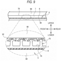
- each of protrusion portions 73 which is a second modification of the protrusion portion has a so-called mushroom shape which is a hook-and-loop fastener. After extending upward from the base portion, an upper end portion protrudes forward and rearward as shown in FIG. 9 , and also protrudes leftward and rightward in the same way as forward and backward, although not shown.
- the protrusion portion 73 has no directivity in the front-rear direction and the left-right direction. Similar to the protrusion portions 72, the protrusion portions 73 firmly hold the fluff or fibers of the cloth hooked, so that an amount of shrinkage of the cloth due to the ink is also reduced in the second modification.
- the protrusion portions 73 may protrude toward any of the front side, rear side, left side and the right side.
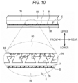
- each of protrusion portions 74 which is a third modification of the protrusion portion has an inverted trapezoidal shape in which a tip end is wider than a base portion in a right side view. Since the protrusion portions 74 can hook the fluff or fibers of the cloth with a simple structure, an amount of shrinkage of the cloth due to the ink is also reduced in the third modification.
- each of protrusion portions 75 which is a fourth modification of the protrusion portion has a needle shape extending in the upper-lower direction.
- a plurality of grooves 76 which are recessed downward from an upper surface 54 of the plate 50 and extend in the front-rear direction and the left-right direction are provided on the platen 5.
- the protrusion portion 75 is provided at an intersection of the groove 76 extending in the front-rear direction and the groove 76 extending in the left-right direction.
- a tip end of the protrusion portion 75 protrudes upward from the upper surface 54 of the plate 50.
- the tip ends of the protrusion portions 75 pierce and hook the cloth placed on the platen 5. Therefore, in the fourth modification, an amount of shrinkage of the cloth due to the ink is also reduced.
- the upper surface 54 of the plate 50 is an example of an "upper surface" of the present disclosure.
- the shape of the protrusion portion may be any shape as long as the tip end hooks the fluff or fibers of the cloth as in the above modification.
- the sheet 7 may be provided with a combination of protrusion portions of different shapes.
- the sheet 7 may be provided with the protrusion portions 71 and the protrusion portions 73 that are alternately arranged in the left-right direction.
- the protrusion portions 71 to 75 may be provided on only a part of the upper surface of the platen 5.
- the protrusion portions 71 to 75 may be provided only on the upper surface of the platen 5 corresponding to a position on the T-shirt 90 (for example, a center portion of the T-shirt 90) at which printing is often performed.
- the shapes of the platen 5 and the plate 50 both are a rectangular shape in which the longitudinal direction is the front-rear direction and the lateral direction is the left-right direction in a plan view, but the present disclosure is not limited thereto.
- the shapes of the platen 5 and the plate 50 may both be a rectangular shape in which the longitudinal direction is the left-right direction and the lateral direction is the front-rear direction in a plan view, or a square shape.
- the T-shirt 90 is removed in the left direction or the right direction, or in a case where the positioning portion 51 is provided at a right end portion or a left end portion of the platen 5
- an example of the first direction is the left-right direction
- an example of the second direction is the front-rear direction.
- the double-sided tape is exemplified as the bonding material 8, but the present disclosure is not limited thereto.
- an adhesive such as glue may be used.
- the plate 50 and the sheet 7 may be fixed by a method other than the bonding material 8.
- the sheet 7 may be fixed by sandwiching the sheet 7 between the plate 50 and a frame portion covering an edge portion of the upper surface of the plate 50. Further, the sheet 7 may be fixed to the upper surface of the plate 50 by both the bonding material 8 and the frame portion.
- a configuration of the positioning portion 51 may be appropriately changed.
- a marker for positioning the collar 91 of the T-shirt 90 may be provided at the front end portion of the upper surface of the plate 50, and the marker may be used as the positioning portion 51. Further, the positioning portion 51 may not be provided on the platen 5.
- the printer 1 may be configured to move the platen 5 in a main scanning direction instead of moving the heads 100 and 200. That is, it is sufficient that the printer 1 moves the heads 100 and 200 and the platen 5 relative to each other.
- At least one of the heads 100 and 200 is mounted on the carriage 20.
- only the head 200 may be mounted on the carriage 20.
- the ink ejected by the heads 100 and 200 may be changed as appropriate.
- the platen 5 moves to the attachment/detachment position and the printing position in the front-rear direction, but the position to which the platen 5 moves is not limited thereto.
- the platen 5 may move to a loading position, the printing position, and a removal position.
- the loading position is the same as the attachment/detachment position shown in FIG. 1 .
- the removal position is a position rearward than the printing position.
- the user sets the cloth on the platen 5 at the loading position.
- the printer 1 moves the platen 5 to the printing position and performs printing on the cloth.
- the printer 1 moves the platen 5 to the removal position.
- the user pulls the cloth rearward and removes the cloth from the platen 5.
- the protrusion portions 71 protrude upward and rearward from the upper surface of the platen 5.
- the platen 5 may include a frame 5Fa.
- the frame 5Fa surrounds the plate 50 of the platen 5 from outside in the front-rear direction and the left-right direction.
- An upper portion of the frame 5Fa extends inward in the front-rear direction and the left-right direction and is in contact with the upper surface 70 of the platen 5.
- the frame 5Fa fixes the cloth on the upper surface 70.
- the platen 5 can reduce the possibility that a position on the cloth at which the ejected ink adheres deviates from a desired position on the cloth.
- the frame 5Fa is not connected to the plate 50 of the platen 50, but may be connected thereto.
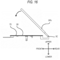
- a frame 5Fb is connected to the plate 50 via a connection portion 5C such as a hinge provided at the rear end of the plate 50. Accordingly, as shown in FIG. 16 , the frame 5Fb can be pivoted upward from a position, at which a front end of the frame 5Fb is in contact the plate 50, around the connection portion 5C. Since the frame 5Fb and the plate 50 are connected, alignment between the frame 5Fb and the plate 50 is facilitated.
- the bonding material 8 and the sheet 7 are not shown.
Landscapes
- Engineering & Computer Science (AREA)
- Textile Engineering (AREA)
- Mechanical Engineering (AREA)
- Ink Jet (AREA)
- Handling Of Sheets (AREA)
- Feeding Of Articles By Means Other Than Belts Or Rollers (AREA)
Abstract
Description
- The present disclosure relates to a platen and a printing device.
- A printing device described in
PTL 1 includes a medium support unit that supports a medium such as cloth from below, and a print head that ejects ink onto the medium to perform printing. - [PTL 1]
JP2018-138362A - In the printing device described above, depending on a type of the cloth, the cloth may shrink when the ink is adhered to the cloth. As a result, there is a possibility that a position on the cloth at which the subsequently ejected ink adheres deviates from a desired position on the cloth.
- An object of the present disclosure is to provide a platen and a printing device capable of reducing a possibility that a position on a cloth at which ejected ink adheres deviates from a desired position on the cloth.
- According to a first aspect of the present disclosure, a platen that supports a cloth onto which ink is to be ejected from an inkjet head includes a plurality of protrusion portions each protruding upward from an upper surface of the platen, in which tip ends of the protrusion portions each have a shape for hooking fluff or fibers of the cloth.
- In the platen of the first aspect, since the tip ends of the protrusion portions hook the fluff or fibers of the cloth, an amount of shrinkage of the cloth due to the ink adhesion is reduced. Accordingly, a possibility that a position on the cloth at which the ejected ink adheres deviates from a desired position on the cloth can be reduced.
- The platen may extend in a first direction orthogonal to an upper-lower direction and in a second direction orthogonal to the upper-lower direction and the first direction, and the plurality of protrusion portions may protrude upward from the upper surface of the platen, and toward an outside of the platen in the first direction and the second direction.
- In this case, the platen can reduce, by the protrusion portions, an amount of shrinkage of the cloth which tends to shrink toward an inside of the platen.
- The plurality of protrusion portions may protrude toward, as the outside, a removal direction in which the cloth is removed from the platen.
- When a user removes the cloth from the platen in the removal direction, since the protrusion portions protrude upward and in the removal direction, hooking between the cloth to be removed and the protrusion portions is reduced.
- The platen may support clothing as the cloth, a positioning portion configured to position a collar of the clothing may be provided at one end portion of the platen in the first direction, and the plurality of protrusion portions each may protrude upward and toward the one end portion.
- When a user removes the clothing from the platen toward the one end portion, since the protrusion portions protrude upward and toward the one end portion, hooking between the clothing to be removed and the protrusion portions is reduced.
- The plurality of protrusion portions may be provided on an entire of the upper surface.
- In this case, an amount of shrinkage of the cloth due to the ink adhesion can be reduced as compared with a case where the protrusion portions are provided on a part of the upper surface of the platen.
- A printing device according to a second aspect of the present disclosure includes: an ink jet head configured to eject ink onto a cloth; and a platen configured to support the cloth, in which the platen includes a plurality of protrusion portions each protruding upward from an upper surface of the platen, and tip ends of the protrusion portions each have a shape for hooking fluff or fibers of the cloth.
- The printing device of the second aspect can achieve the same effects as those of the first aspect.
- The inkjet head may include a base ink jet head configured to eject base ink, and a color inkjet head configured to eject color ink onto the base ink.
- In the printing device, since an amount of shrinkage of the cloth due to the base ink adhesion is reduced, a possibility that a position on the cloth at which the ejected color ink adheres deviates from a position on the cloth at which the base ink adheres can be reduced.
-
- [
FIG. 1] FIG. 1 is a perspective view of aprinter 1 as viewed from a front upper right side. - [
FIG. 2] FIG. 2 is a perspective view of theprinter 1 from which an upper portion of acase 2 is removed, as viewed from a front upper right. - [
FIG. 3] FIG. 3 is a plan view of aplaten 5. - [
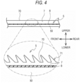
FIG.4] FIG. 4 is a cross-sectional view of theplaten 5 shown inFIG. 3 taken along a line A-A. - [
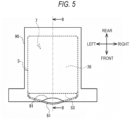
FIG. 5] FIG. 5 is a plan view of theplaten 5 on which a T-shirt 90 is positioned. - [
FIG. 6] FIG. 6 is a cross-sectional view of theplaten 5 and the T-shirt 90 shown inFIG. 5 taken along a line B-B. - [
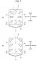
FIG. 7] FIG. 7 is a diagram illustrating a modification of directivity ofprotrusion portions 71 in a horizontal direction. - [
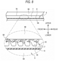
FIG. 8] FIG. 8 is a cross-sectional view of theplaten 5 and the T-shirt 90 shown inFIG. 5 , taken along the line B-B, in a case whereprotrusion portions 72 are provided. - [
FIG. 9] FIG. 9 is a cross-sectional view of theplaten 5 and the T-shirt 90 shown inFIG. 5 , taken along the line B-B, in a case whereprotrusion portions 73 are provided. - [
FIG. 10] FIG. 10 is a cross-sectional view of theplaten 5 and the T-shirt 90 shown inFIG. 5 , taken along the line B-B, in a case whereprotrusion portions 74 are provided. - [
FIG. 11] FIG. 11 is a plan view of theplaten 5 provided withprotrusion portions 75. - [
FIG. 12] FIG. 12 is a cross-sectional view of theplaten 5 shown inFIG. 11 taken along a line C-C. - [
FIG. 13] FIG. 13 is a perspective view of theplaten 5 in a case where a frame 5Fa is provided, as viewed from a front upper right side. - [
FIG. 14] FIG. 14 is a view of theplaten 5 as viewed from a right side when the frame 5Fa is provided. - [
FIG. 15] FIG. 15 is a perspective view of theplaten 5 in a case where a frame 5Fb is provided, as viewed from a front upper right side. - [
FIG. 16] FIG. 16 is a view of theplaten 5 as viewed from a right side in a case where the frame 5Fb is provided. - A
printer 1 and aplaten 5 according to an embodiment of the present disclosure will be described with reference to the drawings. Theprinter 1 shown inFIG. 1 is an inkjet printer and performs printing by ejecting ink onto a cloth which is a print medium. The cloth is, for example, a fabric including cotton and silk, felt, or the like, and is a T-shirt 90 in the present embodiment. An upper side, a lower side, a lower left side, an upper right side, a lower right side, and an upper left side inFIG. 1 correspond to an upper side, a lower side, a front side, a rear side, a right side, and a left side of theprinter 1 and theplaten 5, respectively. In the present embodiment, mechanical elements in the drawings represent actual scales. - A schematic configuration of the
printer 1 will be described with reference toFIG. 1 . As shown inFIG. 1 , theprinter 1 incudes acase 2, aconveying unit 6, aplaten support member 3, and theplaten 5. Thecase 2 has a rectangular parallelepiped shape. Anopening portion 21 is formed in thecase 2. Theopening portion 21 extends from a front surface to a rear surface of thecase 2. Aninput unit 46 is provided on a right side of theopening portion 21 in the front surface of thecase 2. A user inputs various types of information to theprinter 1 by operating theinput unit 46. - The
conveying unit 6 is provided below theopening portion 21, and conveys theplaten support member 3 in a front-rear direction. Specifically, theconveying unit 6 includes a pair ofrails 12 shown inFIG. 2 . The pair ofrails 12 are arrange in a left-right direction and extend in the front-rear direction. Theplaten support member 3 is located above theconveying unit 6 and supported by the pair ofrails 12. A sub-scanning motor (not shown) is provided below theplaten support member 3. The platen support member3 can be moved in the front-rear direction along the pair ofrails 12 by driving the sub-scanning motor. - The
platen 5 is disposed inside theopening portion 21 in a front view. Theplaten 5 is supported by theplaten support member 3 and moves in the front-rear direction between a printing position and an attachment/detachment position together with theplaten support member 3. That is, the front-rear direction of theprinter 1 is a sub-scanning direction. The printing position is a position at which theplaten 5 facesheads case 2, which are to be described later. The attachment/detachment position is on a front side of the printing position, and is shown inFIG. 1 . When theplaten 5 is at the attachment/detachment position, theplaten support member 3 and theplaten 5 reach front end portions of the pair ofrails 12, and theplaten support member 3 is disposed outside thecase 2. Details of a structure of theplaten 5 will be described later. As an example of the cloth, the T-shirt 90 is placed on an upper surface of theplaten 5. - As shown in
FIG. 2 , theprinter 1 includes, inside thecase 2 shown inFIG. 1 , arail 11, aguide shaft 9, acarriage 20, and theheads rail 11 is provided in an upper rear portion of theprinter 1 and extends in the left-right direction. Theguide shaft 9 is provided in front of therail 11 and extends in the left-right direction. Thecarriage 20 is located between therail 11 and theguide shaft 9 in the front-rear direction, and is supported by therail 11 and theguide shaft 9. Amain scanning motor 19 is provided on a right side of a right end portion of theguide shaft 9. Thecarriage 20 can move in the left-right direction along therail 11 and theguide shaft 9 when driven by themain scanning motor 19. - The
heads carriage 20, and move in the left-right direction together with thecarriage 20. Thehead 100 is located rearward than thehead 200. Each of theheads - The
printer 1 can print a color image on the print medium using ink of five colors including white, black, yellow, cyan, and magenta. Hereinafter, among the ink of five colors, the ink of a white color is referred to as white ink, and the ink of four colors including black, cyan, yellow, and magenta are collectively referred to as color ink. When the white ink and the color ink are collectively referred to, or when either one is not specified, the white ink and the color ink are simply referred to as ink. The white ink is used in printing as a portion representing a white color on the image or as a base of the ink of other colors. The color ink is ejected onto a base made of the white ink and used in printing of the color image. - The
head 100 ejects the white ink from the nozzle thereof. Thehead 200 ejects the color ink from the nozzle thereof. - An example of a detailed structure of the
platen 5 will be described with reference toFIGS. 3 and4 . Theplaten 5 includes aplate 50, abonding material 8, and asheet 7. Theplate 50 extends in the front-rear direction and the left-right direction, has a rectangular shape elongated in the front-rear direction in a plan view, and is made of, for example, metal. On an upper surface of theplate 50, thebonding material 8 and thesheet 7 are stacked in order from below. Thebonding material 8 is, for example, a double-sided tape, and fixes theplate 50 and thesheet 7. As shown inFIG. 3 , thesheet 7 covers the entire upper surface of theplate 50 in a plan view. Accordingly, theplaten 5 has the same shape as theplate 50 in a plan view, and has a rectangular shape in which a longitudinal direction is the front-rear direction and a lateral direction is the left-right direction in a plan view. - As shown in
FIG. 4 , a plurality ofprotrusion portions 71 are arranged at predetermined intervals on an entire of anupper surface 70 of thesheet 7. For example, theprotrusion portion 71 protrudes upward and forward from theupper surface 70 of thesheet 7. The plurality ofprotrusion portions 71 are, for example, a member of a hook-and-loop fastener on a side raised in a hook shape. Theprotrusion portion 71 tapers from a base portion thereof toward a tip end thereof. A height of theprotrusion portion 71 is, for example, 1.7 mm. Each of theprotrusion portions 71 tapers from a base portion thereof toward a tip end thereof. As shown inFIG. 6 , the tip endshook fibers 92 of the T-shirt 90 which is set on theplaten 5. Further, since theprotrusion portions 71 protrude upward and forward from theupper surface 70 of thesheet 7, when the T-shirt 90 is pulled forward and removed from theplaten 5, hooking between the T-shirt 90 to be removed and theprotrusion portions 71 is reduced. - As shown in
FIG. 3 , apositioning portion 51 is provided at afront end portion 53 of theplaten 5. The positioningportion 51 is a rod-shaped member extending forward from both left and right sides toward a center in a plan view. A rear end portion of thepositioning portion 51 is fastened to theplate 50 by fastening members (not shown) via a plurality ofholes 52 penetrating a right front portion and a left front portion of theplate 50 in an upper-lower direction. - An outline of printing performed by the
printer 1 will be described with reference toFIGS. 1 ,2 ,5 and6 . First, the user operates theinput unit 46 to move theplaten 5 to the attachment/detachment position shown inFIG. 1 . The user holds a hem of the T-shirt 90 with acollar 91 of the T-shirt 90 facing forward and a body length being in the front-rear direction, and moves the T-shirt 90 backward so as to cover theplaten 5 from a hem side. At this time, the T-shirt 90 is moved in a state of being separated upward from thesheet 7. - As shown in
FIG. 5 , thecollar 91 comes into contact with thepositioning portion 51, and positioning of the T-shirt 90 with respect to theplaten 5 is completed. The user places the T-shirt 90 on thesheet 7 to set the T-shirt 90 on theplaten 5. At this time, as shown inFIG. 6 , the tip ends of theprotrusion portions 71 hook thefibers 92 of the T-shirt 90 set on theplaten 5. The user operates theinput unit 46 to move theplaten 5 on which the T-shirt 90 is set from the attachment/detachment position to the printing position. - The
printer 1 ejects white ink from thehead 100 and color ink from thehead 200 while causing thecarriage 20 to scan in the left-right direction. When the ejection of ink in one scan is completed, theprinter 1 moves theplaten 5 forward and ejects ink from theheads carriage 20 to scan in the left-right direction again. Since thehead 100 is located rearward than thehead 200, the color ink is ejected onto the white ink. That is, the white ink is used as a base of the color ink. - When the white ink ejected from the
head 100 adheres to the T-shirt 90 as a base, the white ink may cause the T-shirt 90 to shrink. When the T-shirt 90 shrinks, there is a possibility that a position on the T-shirt 90 at which the color ink ejected thereafter adheres deviates from a position on the T-shirt 90 at which the white ink adheres. Since the tip ends of theprotrusion portions 71 of theplaten 5 hook thefibers 92 of the T-shirt 90, an amount of shrinkage of the T-shirt 90 due to the white ink is reduced. Accordingly, a possibility that the position on the T-shirt 90 at which the color ink adheres deviates from the position on the T-shirt 90 at which the white ink adheres is reduced, and a desired print result is obtained. - When the printing on the T-
shirt 90 is completed, theprinter 1 moves theplaten 5 to the attachment/detachment position shown inFIG. 1 . The user holds thecollar 91 and pulls the T-shirt 90 forward to remove the T-shirt 90 from theplaten 5. At this time, the T-shirt 90 slides on thesheet 7. Since each of theprotrusion portions 71 protrudes upward and forward from theupper surface 70 of thesheet 7, the T-shirt 90 sliding on thesheet 7 can be removed from theplaten 5 without being hooked by theprotrusion portions 71. - As described above, the
platen 5 includes theplate 50, thebonding material 8, and thesheet 7. On the upper surface of theplate 50, thebonding material 8 and thesheet 7 are stacked in order from below. Thesheet 7 includes the plurality ofprotrusion portions 71 arranged at predetermined intervals. Each of theprotrusion portions 71 protrudes upward and forward from theupper surface 70 of thesheet 7. As shown inFIG. 6 , the tip ends of theprotrusion portions 71 hook thefibers 92 of the T-shirt 90 set on theplaten 5. As a result, the amount of shrinkage of the T-shirt 90 due to the ink adhesion is reduced. Accordingly, theplaten 5 can reduce the possibility that the position on the T-shirt 90 at which the ejected ink adheres deviates from a desired position on the T-shirt 90. - The plurality of
protrusion portions 71 are arranged at predetermined intervals on the entireupper surface 70 of thesheet 7. In this case, the amount of shrinkage of the T-shirt 90 due to the ink adhesion can be reduced as compared with a case where theprotrusion portions 71 are provided on a part of theupper surface 70 of thesheet 7 of theplaten 5. - The
platen 5 extends in the front-rear direction and the left-right direction, and each of theprotrusion portions 71 protrudes upward and forward from theupper surface 70 of thesheet 7. When the user pulls the T-shirt 90 forward to remove the T-shirt 90 from theplaten 5, the hooking between the T-shirt 90 to be removed and theprotrusion portions 71 is reduced. - The positioning
portion 51 that positions thecollar 91 of the T-shirt 90 is provided at thefront end portion 53 of theplaten 5. Each of theprotrusion portions 71 protrudes upward and forward. That is, theprotrusion portions 71 protrudes toward thefront end portion 53 of theplaten 5. Thus, when the user holds thecollar 91 and pulls the T-shirt 90 forward at the time of removing the T-shirt 90 from theplaten 5, the hooking between the T-shirt 90 to be removed and theprotrusion portions 71 is reduced. - The
printer 1 includes theheads shirt 90 and theplaten 5 that supports the T-shirt 90. Since the tip ends of theprotrusion portions 71 of theplaten 5 hook thefibers 92 of the T-shirt 90, the amount of shrinkage of the T-shirt 90 due to the ink adhesion is reduced. Accordingly, theprinter 1 can reduced the possibility that the position on the T-shirt 90 at which the ejected ink adheres deviates from the desired position on the T-shirt 90. - The
printer 1 includes thehead 100 for ejecting the white ink used in printing as a base, and thehead 200 for ejecting the color ink on the white ink. In theprinter 1, the amount of shrinkage of the T-shirt 90 due to the white ink is reduced, so that a possibility that the position on the T-shirt 90 at which the ejected color ink adheres deviates from a position on the cloth at which the white ink adheres can be reduced. - In the above embodiment, the
heads shirt 90 corresponds to a "cloth" or "clothing" of the present disclosure. Theprinter 1 corresponds to a "printing device" of the present disclosure. The white ink corresponds to a "base ink" of the present disclosure. Thehead 100 corresponds to a "base ink jet head" of the present disclosure. Thehead 200 corresponds to a "color ink jet head" of the present disclosure. Theplate 50 extends in a first direction and a second direction. An example of the first direction is the front-rear direction, and an example of the second direction is the left-right direction. The T-shirt 90 is pulled forward and removed from theplaten 5. An example of the removal direction is the forward direction. Theupper surface 70 of thesheet 7 is an example of an "upper surface" of the present disclosure. Thefront end portion 53 of theplaten 5 is an example of a "one end portion" of the present disclosure. - The present disclosure can be variously modified from the above embodiment. Various modifications to be described below can be combined as long as no contradiction occurs. For example, the present disclosure can be applied to a printer of a type different from the ink jet type in the above embodiment.
- In the above embodiment, the T-
shirt 90 is exemplified as the cloth, but the present disclosure is not limited thereto. The cloth may be, for example, various shirts such as a dress shirt; pants; skirts; handkerchiefs; or a textile itself. The cloth is not limited to a fabric including cotton and silk, and may be non-woven cloth such as felt. The tip ends of theprotrusion portions 71 are not limited to being hooked with fibers of the cloth, and may be hooked with fluff of the cloth. Even when the printing is performed on the non-woven cloth, an amount of shrinkage of the non-woven cloth due to the ink adhesion is reduced by the tip ends of theprotrusion portions 71. Accordingly, theplaten 5 can reduce a possibility that a position on the non-woven cloth at which the ejected ink adheres deviates from a desired position on the non-woven cloth. - In the above embodiment, the
protrusion portions 71 protrude upward and forward from the upper surface of theplaten 5, but the direction in which theprotrusion portions 71 protrude is not limited thereto. For example, as shown in (A) ofFIG. 7 , theprotrusion portions 71 protrude upward. Theprotrusion portions 71 may further protrude outward in a radial manner in the front-rear direction and the left-right direction from the center of theplaten 5. On the T-shirt 90 set on theplaten 5, an image is often printed at a position corresponding to the center of the upper surface of theplaten 5, and the T-shirt 90 tends to shrink toward an inside of theplaten 5 in the front-rear direction and the left-right direction due to the ink. Since theprotrusion portions 71 protrude in the above-described directions, the tip ends of theprotrusion portions 71 easily hook the fluff or fibers of the cloth. Therefore, theplaten 5 can reduce an amount of shrinkage of the T-shirt 90 that tends to shrink inward. - Further, as shown in (B) of
FIG. 7 , theprotrusion portions 71 may protrude in a radial manner from a central portion in the left-right direction of a rear end portion of theplaten 5 instead of protruding from the center of theplaten 5. In this case, theplaten 5 can reduce an amount of shrinkage of the T-shirt 90 that tends to shrink inward, and reduce the hooking between the T-shirt 90 to be pulled forward and removed, and theprotrusion portions 71. - The shape of the protrusion portion may be changed as appropriate. The shape of the protrusion portion may be any shape as long as the tip end hooks the fluff or fibers of the cloth. A shape in which the tip end of the protrusion portion hooks the fluff or fibers of the cloth is, for example, a shape in which the tip end of the protrusion portion protrudes toward at least one of the front side, the rear side, the left side and the right side with respect to the base portion. It is desirable that the protrusion portion has a hook shape that extends upward from the base portion and protrudes toward at least one of the front side, the rear side, the left side and the right side therefrom, or a shape having a corner without a curved tip end. A member having such a shape is provided, for example, on a member of a hook-and-loop fastener on a side raised in a hook shape. Further, the protrusion portions may be a fibrous material or a raised material, such as those found in clothing or a brush for a vacuum cleaner. The fibrous material as the protrusion portions may protrude upward from the
upper surface 70 of thesheet 7 by several millimeters. It is desirable that the protrusion portions protrude upward and toward at least one of the front side, the rear side, the left side and the right side, and it is preferable that the protrusion portions protrude toward the front side among the directions which is a direction in which the T-shirt 90 is to be removed. - As shown in
FIG. 8 , each ofprotrusion portions 72 which is a first modification of the protrusion portion has an inverted J-shape, and has a shape in which theprotrusion portion 72 extends upward while being tapered from a base portion thereof toward a tip end thereof in a right side view, and then extends forward while being curved. Since theprotrusion portions 72 firmly hold the fluff or fibers of the cloth hooked, an amount of shrinkage of the cloth due to the ink is also reduced in the first modification. - Further, each of
protrusion portions 73 which is a second modification of the protrusion portion has a so-called mushroom shape which is a hook-and-loop fastener. After extending upward from the base portion, an upper end portion protrudes forward and rearward as shown inFIG. 9 , and also protrudes leftward and rightward in the same way as forward and backward, although not shown. Theprotrusion portion 73 has no directivity in the front-rear direction and the left-right direction. Similar to theprotrusion portions 72, theprotrusion portions 73 firmly hold the fluff or fibers of the cloth hooked, so that an amount of shrinkage of the cloth due to the ink is also reduced in the second modification. Theprotrusion portions 73 may protrude toward any of the front side, rear side, left side and the right side. - Further, as shown in
FIG. 10 , each ofprotrusion portions 74 which is a third modification of the protrusion portion has an inverted trapezoidal shape in which a tip end is wider than a base portion in a right side view. Since theprotrusion portions 74 can hook the fluff or fibers of the cloth with a simple structure, an amount of shrinkage of the cloth due to the ink is also reduced in the third modification. - As shown in
FIGS. 11 and12 , each ofprotrusion portions 75 which is a fourth modification of the protrusion portion has a needle shape extending in the upper-lower direction. A plurality ofgrooves 76 which are recessed downward from anupper surface 54 of theplate 50 and extend in the front-rear direction and the left-right direction are provided on theplaten 5. Theprotrusion portion 75 is provided at an intersection of thegroove 76 extending in the front-rear direction and thegroove 76 extending in the left-right direction. A tip end of theprotrusion portion 75 protrudes upward from theupper surface 54 of theplate 50. The tip ends of theprotrusion portions 75 pierce and hook the cloth placed on theplaten 5. Therefore, in the fourth modification, an amount of shrinkage of the cloth due to the ink is also reduced. In the fourth modification, theupper surface 54 of theplate 50 is an example of an "upper surface" of the present disclosure. - The shape of the protrusion portion may be any shape as long as the tip end hooks the fluff or fibers of the cloth as in the above modification. The
sheet 7 may be provided with a combination of protrusion portions of different shapes. For example, thesheet 7 may be provided with theprotrusion portions 71 and theprotrusion portions 73 that are alternately arranged in the left-right direction. - The
protrusion portions 71 to 75 may be provided on only a part of the upper surface of theplaten 5. For example, theprotrusion portions 71 to 75 may be provided only on the upper surface of theplaten 5 corresponding to a position on the T-shirt 90 (for example, a center portion of the T-shirt 90) at which printing is often performed. - In the above embodiment, the shapes of the
platen 5 and theplate 50 both are a rectangular shape in which the longitudinal direction is the front-rear direction and the lateral direction is the left-right direction in a plan view, but the present disclosure is not limited thereto. The shapes of theplaten 5 and theplate 50 may both be a rectangular shape in which the longitudinal direction is the left-right direction and the lateral direction is the front-rear direction in a plan view, or a square shape. In a case where the T-shirt 90 is removed in the left direction or the right direction, or in a case where thepositioning portion 51 is provided at a right end portion or a left end portion of theplaten 5, an example of the first direction is the left-right direction, and an example of the second direction is the front-rear direction. - In the above embodiment, the double-sided tape is exemplified as the
bonding material 8, but the present disclosure is not limited thereto. For example, an adhesive such as glue may be used. Further, theplate 50 and thesheet 7 may be fixed by a method other than thebonding material 8. For example, thesheet 7 may be fixed by sandwiching thesheet 7 between theplate 50 and a frame portion covering an edge portion of the upper surface of theplate 50. Further, thesheet 7 may be fixed to the upper surface of theplate 50 by both thebonding material 8 and the frame portion. - A configuration of the
positioning portion 51 may be appropriately changed. For example, a marker for positioning thecollar 91 of the T-shirt 90 may be provided at the front end portion of the upper surface of theplate 50, and the marker may be used as thepositioning portion 51. Further, the positioningportion 51 may not be provided on theplaten 5. - For example, the
printer 1 may be configured to move theplaten 5 in a main scanning direction instead of moving theheads printer 1 moves theheads platen 5 relative to each other. - It is sufficient that at least one of the
heads carriage 20. For example, only thehead 200 may be mounted on thecarriage 20. The ink ejected by theheads - In the above embodiment, the
platen 5 moves to the attachment/detachment position and the printing position in the front-rear direction, but the position to which theplaten 5 moves is not limited thereto. For example, theplaten 5 may move to a loading position, the printing position, and a removal position. The loading position is the same as the attachment/detachment position shown inFIG. 1 . The removal position is a position rearward than the printing position. When theplaten 5 is at the removal position, theplaten support member 3 and theplaten 5 reach rear end portions of the pair ofrails 12. - The user sets the cloth on the
platen 5 at the loading position. Theprinter 1 moves theplaten 5 to the printing position and performs printing on the cloth. When the printing is completed, theprinter 1 moves theplaten 5 to the removal position. The user pulls the cloth rearward and removes the cloth from theplaten 5. In the modification, since the cloth is pulled rearward and removed from theplaten 5, it is desirable that theprotrusion portions 71 protrude upward and rearward from the upper surface of theplaten 5. - The
platen 5 may include a frame 5Fa. As shown inFIG. 13 , the frame 5Fa surrounds theplate 50 of theplaten 5 from outside in the front-rear direction and the left-right direction. An upper portion of the frame 5Fa extends inward in the front-rear direction and the left-right direction and is in contact with theupper surface 70 of theplaten 5. Thus, in a state where the cloth is set on theupper surface 70, as shown inFIG. 14 , when the frame 5Fa is placed on theplate 50 from above, the frame 5Fa fixes the cloth on theupper surface 70. As a result, since the cloth set on theplaten 5 is hooked by the tip ends of theprotrusion portions 71 to 75 and is sandwiched by the frame 5Fa, an amount of shrinkage of the cloth due to the ink adhesion is reduced. Therefore, theplaten 5 can reduce the possibility that a position on the cloth at which the ejected ink adheres deviates from a desired position on the cloth. - In
FIGS. 13 and14 , the frame 5Fa is not connected to theplate 50 of theplaten 50, but may be connected thereto. As shown inFIG. 15 , a frame 5Fb is connected to theplate 50 via aconnection portion 5C such as a hinge provided at the rear end of theplate 50. Accordingly, as shown inFIG. 16 , the frame 5Fb can be pivoted upward from a position, at which a front end of the frame 5Fb is in contact theplate 50, around theconnection portion 5C. Since the frame 5Fb and theplate 50 are connected, alignment between the frame 5Fb and theplate 50 is facilitated. InFIGS. 13 to 16 , thebonding material 8 and thesheet 7 are not shown. -
- 1 printer
- 5 platen
- 7 sheet
- 8 bonding material
- 50 plate
- 51 positioning portion
- 53 front end portion
- 54, 70 upper surface
- 71 to 75 protrusion portion
- 76 groove
- 100, 200 head
Claims (7)
- A platen that supports a cloth onto which ink is to be ejected from an inkjet head, the platen comprising:a plurality of protrusion portions each protruding upward from an upper surface of the platen,wherein tip ends of the protrusion portions each have a shape for hooking fluff or fibers of the cloth.
- The platen according to claim 1,wherein the platen extends in a first direction orthogonal to an upper-lower direction and in a second direction orthogonal to the upper-lower direction and the first direction, andthe plurality of protrusion portions protrude upward from the upper surface of the platen, and toward an outside of the platen in the first direction and the second direction.
- The platen according to claim 2,
wherein the plurality of protrusion portions protrude toward, as the outside, a removal direction in which the cloth is removed from the platen. - The platen according to claim 2 or 3,wherein the platen supports clothing as the cloth,a positioning portion configured to position a collar of the clothing is provided at one end portion of the platen in the first direction, andthe plurality of protrusion portions each protrude upward and toward the one end portion.
- The platen according to any one of claims 1 to 4,
wherein the plurality of protrusion portions are provided on an entire of the upper surface. - A printing device comprising:an inkjet head configured to eject ink onto a cloth; anda platen configured to support the cloth,wherein the platen includes a plurality of protrusion portions each protruding upward from an upper surface of the platen, andtip ends of the protrusion portions each have a shape for hooking fluff or fibers of the cloth.
- The printing device according to claim 6,
wherein the inkjet head includes:a base inkjet head configured to eject base ink; anda color ink jet head configured to eject color ink onto the base ink.
Applications Claiming Priority (2)
| Application Number | Priority Date | Filing Date | Title |
|---|---|---|---|
| JP2021022106A JP2022124373A (en) | 2021-02-15 | 2021-02-15 | Platen and printer |
| PCT/JP2022/003263 WO2022172779A1 (en) | 2021-02-15 | 2022-01-28 | Platen and printing device |
Publications (2)
| Publication Number | Publication Date |
|---|---|
| EP4292966A1 true EP4292966A1 (en) | 2023-12-20 |
| EP4292966A4 EP4292966A4 (en) | 2025-01-29 |
Family
ID=82838762
Family Applications (1)
| Application Number | Title | Priority Date | Filing Date |
|---|---|---|---|
| EP22752608.4A Pending EP4292966A4 (en) | 2021-02-15 | 2022-01-28 | PRESSURE SUPPORT AND PRESSURE DEVICE |
Country Status (5)
| Country | Link |
|---|---|
| US (1) | US12522005B2 (en) |
| EP (1) | EP4292966A4 (en) |
| JP (2) | JP2022124373A (en) |
| CN (1) | CN116249663B (en) |
| WO (1) | WO2022172779A1 (en) |
Families Citing this family (1)
| Publication number | Priority date | Publication date | Assignee | Title |
|---|---|---|---|---|
| JP7666036B2 (en) * | 2021-03-17 | 2025-04-22 | 株式会社リコー | Liquid ejection device, platen member |
Family Cites Families (22)
| Publication number | Priority date | Publication date | Assignee | Title |
|---|---|---|---|---|
| US6634744B2 (en) * | 2001-03-23 | 2003-10-21 | Konica Corporation | Ink-jet printer |
| JP4147794B2 (en) * | 2001-03-23 | 2008-09-10 | コニカミノルタホールディングス株式会社 | Inkjet printer |
| JP4055622B2 (en) * | 2003-03-27 | 2008-03-05 | ブラザー工業株式会社 | Fabric printing apparatus and platen used therefor |
| JP4696955B2 (en) * | 2006-02-21 | 2011-06-08 | ブラザー工業株式会社 | Fabric printing device |
| JP4973015B2 (en) * | 2006-06-02 | 2012-07-11 | ブラザー工業株式会社 | Embroidery frame |
| JP2008080750A (en) | 2006-09-28 | 2008-04-10 | Brother Ind Ltd | Printing device |
| US7854200B2 (en) | 2007-01-06 | 2010-12-21 | Livingston John C | Hold down device for material placed on platen of digital printing machine |
| US9297097B2 (en) * | 2012-06-22 | 2016-03-29 | Nike, Inc. | Knit article of apparel and apparel printing system and method |
| US9272538B2 (en) * | 2012-10-05 | 2016-03-01 | Darren Livingston | Digital printer platen material holding apparatus |
| JP6521510B2 (en) * | 2015-01-23 | 2019-05-29 | 株式会社ミマキエンジニアリング | inkjet printer |
| JP6466731B2 (en) * | 2015-02-13 | 2019-02-06 | 株式会社ミマキエンジニアリング | Inkjet printing device |
| JP6528492B2 (en) * | 2015-03-23 | 2019-06-12 | セイコーエプソン株式会社 | Liquid injection device |
| JP6739916B2 (en) * | 2015-09-29 | 2020-08-12 | キヤノン株式会社 | Printing equipment |
| EP3162577B1 (en) * | 2015-10-27 | 2020-08-12 | Agfa Nv | Inkjet printing method for heat sensitive substrates |
| JP6703301B2 (en) * | 2016-02-22 | 2020-06-03 | セイコーエプソン株式会社 | Printer |
| JP6711019B2 (en) * | 2016-02-29 | 2020-06-17 | セイコーエプソン株式会社 | Conveying device and printing device |
| JP2017159472A (en) * | 2016-03-07 | 2017-09-14 | セイコーエプソン株式会社 | Medium support unit and printing apparatus |
| US10632761B2 (en) * | 2016-05-06 | 2020-04-28 | Ricoh Company, Ltd. | Printer, cloth holder, holder with cloth, and cloth printing system |
| CN206154921U (en) * | 2016-10-25 | 2017-05-10 | 广州市爱司凯科技股份有限公司 | Inkjet printer work platform |
| JP2018138362A (en) | 2017-02-24 | 2018-09-06 | セイコーエプソン株式会社 | Medium support unit, printing device, and friction member attaching and detaching method |
| JP7056067B2 (en) * | 2017-10-11 | 2022-04-19 | セイコーエプソン株式会社 | How to attach the medium support unit, printing device and cover |
| JP7031449B2 (en) | 2018-03-30 | 2022-03-08 | ブラザー工業株式会社 | Platen transfer device and platen transfer device |
-
2021
- 2021-02-15 JP JP2021022106A patent/JP2022124373A/en active Pending
-
2022
- 2022-01-28 CN CN202280006584.6A patent/CN116249663B/en active Active
- 2022-01-28 EP EP22752608.4A patent/EP4292966A4/en active Pending
- 2022-01-28 WO PCT/JP2022/003263 patent/WO2022172779A1/en not_active Ceased
-
2023
- 2023-08-15 US US18/233,960 patent/US12522005B2/en active Active
-
2024
- 2024-09-27 JP JP2024168361A patent/JP2024169718A/en active Pending
Also Published As
| Publication number | Publication date |
|---|---|
| JP2024169718A (en) | 2024-12-05 |
| US12522005B2 (en) | 2026-01-13 |
| JP2022124373A (en) | 2022-08-25 |
| CN116249663A (en) | 2023-06-09 |
| US20230382137A1 (en) | 2023-11-30 |
| EP4292966A4 (en) | 2025-01-29 |
| WO2022172779A1 (en) | 2022-08-18 |
| CN116249663B (en) | 2026-01-16 |
Similar Documents
| Publication | Publication Date | Title |
|---|---|---|
| CN103072375B (en) | Ink-jet printing device | |
| JP4055622B2 (en) | Fabric printing apparatus and platen used therefor | |
| EP1820655A1 (en) | Printing apparatus | |
| JP2013096018A (en) | Printing system and printing method | |
| JP5355862B2 (en) | Inkjet recording method | |
| US12522005B2 (en) | Platen and printing device | |
| JP2013226657A (en) | Set tray, inkjet textile printing apparatus, and manufacturing method of printed matter | |
| JP2005045644A (en) | Inkjet recording device | |
| JP6705197B2 (en) | Printing device and medium supporting method | |
| JPH10168765A (en) | Textile printer | |
| JP5843061B2 (en) | Inkjet printing device | |
| JPH11254657A (en) | Ink jet printer for card and image forming method | |
| JP6428301B2 (en) | Liquid discharge head, liquid discharge unit, and apparatus for discharging liquid | |
| EP1520716B1 (en) | Inkjet printing device | |
| JP3856079B2 (en) | Printer | |
| JP2005199523A (en) | Inkjet recording device | |
| JP2021146664A (en) | Maintenance jig, liquid discharge device, head cleaning method, unit, and liquid discharge system | |
| JP7666036B2 (en) | Liquid ejection device, platen member | |
| JP7056067B2 (en) | How to attach the medium support unit, printing device and cover | |
| JP2003072041A (en) | Drawing equipment | |
| JPH06305131A (en) | Ink jet printing method | |
| US20260091597A1 (en) | Auxiliary member | |
| CN103072388A (en) | Printing apparatus | |
| JP2004181734A (en) | Recording device, computer program, computer system, and recording method | |
| JP6996202B2 (en) | How to hold the printing device and holding part |
Legal Events
| Date | Code | Title | Description |
|---|---|---|---|
| STAA | Information on the status of an ep patent application or granted ep patent |
Free format text: STATUS: THE INTERNATIONAL PUBLICATION HAS BEEN MADE |
|
| PUAI | Public reference made under article 153(3) epc to a published international application that has entered the european phase |
Free format text: ORIGINAL CODE: 0009012 |
|
| STAA | Information on the status of an ep patent application or granted ep patent |
Free format text: STATUS: REQUEST FOR EXAMINATION WAS MADE |
|
| 17P | Request for examination filed |
Effective date: 20230809 |
|
| AK | Designated contracting states |
Kind code of ref document: A1 Designated state(s): AL AT BE BG CH CY CZ DE DK EE ES FI FR GB GR HR HU IE IS IT LI LT LU LV MC MK MT NL NO PL PT RO RS SE SI SK SM TR |
|
| P01 | Opt-out of the competence of the unified patent court (upc) registered |
Effective date: 20231228 |
|
| DAV | Request for validation of the european patent (deleted) | ||
| DAX | Request for extension of the european patent (deleted) | ||
| A4 | Supplementary search report drawn up and despatched |
Effective date: 20250108 |
|
| RIC1 | Information provided on ipc code assigned before grant |
Ipc: B41J 2/21 20060101ALN20241223BHEP Ipc: B65H 5/04 20060101ALI20241223BHEP Ipc: B41J 11/06 20060101ALI20241223BHEP Ipc: B41J 3/407 20060101ALI20241223BHEP Ipc: B41J 11/02 20060101ALI20241223BHEP Ipc: B65H 5/18 20060101AFI20241223BHEP |