EP4292965A1 - Loading platform with interlock - Google Patents
Loading platform with interlock Download PDFInfo
- Publication number
- EP4292965A1 EP4292965A1 EP23177569.3A EP23177569A EP4292965A1 EP 4292965 A1 EP4292965 A1 EP 4292965A1 EP 23177569 A EP23177569 A EP 23177569A EP 4292965 A1 EP4292965 A1 EP 4292965A1
- Authority
- EP
- European Patent Office
- Prior art keywords
- supporting plate
- seat
- loading platform
- foot
- locking
- Prior art date
- Legal status (The legal status is an assumption and is not a legal conclusion. Google has not performed a legal analysis and makes no representation as to the accuracy of the status listed.)
- Granted
Links
Images


Classifications
-
- B—PERFORMING OPERATIONS; TRANSPORTING
- B65—CONVEYING; PACKING; STORING; HANDLING THIN OR FILAMENTARY MATERIAL
- B65G—TRANSPORT OR STORAGE DEVICES, e.g. CONVEYORS FOR LOADING OR TIPPING, SHOP CONVEYOR SYSTEMS OR PNEUMATIC TUBE CONVEYORS
- B65G69/00—Auxiliary measures taken, or devices used, in connection with loading or unloading
- B65G69/28—Loading ramps; Loading docks
- B65G69/2805—Loading ramps; Loading docks permanently installed on the dock
- B65G69/2811—Loading ramps; Loading docks permanently installed on the dock pivoting ramps
Definitions
- the present invention relates to a loading platform with a supporting plate which at its loading platform side rotatably is connected to the loading platform and which from there along can be turned downwards from out of a rest position or upright position, in which the supporting plate stands substantially upright, into a lying position, in which the supporting plate lies substantially horizontal or flat and can form a bridging between the loading platform and the loading floor of a vehicle that is to be loaded and unloaded, with locking means for the locking of the supporting plate in the upright position.
- Such a loading platform is known.
- loading flap or lip With loading platforms there is the standard that a supporting plate, also referred to as loading flap or lip, must be locked when this stands upright, that is to say, is in the rest position. This so as to prevent that the loading flap unintentionally falls down, for instance when this is being leaned against.
- the invention aims to obviate this drawback of the known loading platform.
- the loading platform according to the invention to that end is characterized, in that the locking means are formed in that the loading platform is provided with a body with a seat, while the supporting plate is provided with a locking part that, as seen in the upright position of the supporting plate, at a portion above, via a first hinge point is suspended on the supporting plate and from out there can make a turning movement running perpendicular to the plane of the supporting plate, while a portion below comprises a foot by means of which the locking part can rest on the seat, and by means of which a turning downwards of the supporting plate is held up, whereby an operating means is provided by which the foot can be turned off the seat, whereby further means are provided by which, after the foot has been turned off the seat, it can be prevented that the foot turns back again onto the seat.
- the loading platform 1 comprises at the front side a supporting plate 2 provided rotatably.
- the supporting plate 2 can be turned from out of a rest position or upright position, in which the supporting plate 2 stands substantially upright ( figures 1 , 2 , 3 4 , 5a and 5b ) downwards into a lying position, in which the supporting plate 2 lies substantially horizontal or flat ( figure 5d ) and in this way can form a bridging between the loading platform 1 and the loading floor of a vehicle that is to be loaded and unloaded (not shown in the figures).
- interlocking means so that the supporting plate 2. when this stands in the upright position, can be locked in that position, so that this does not unintentionally smack down and cause damage to persons.
- the supporting plate 2 is provided on the back side 6 with, in this example of an embodiment, a. substantially rod-shaped, holding part 15.
- the holding part at an upper end 16, is suspended on the supporting plate 2 via a second hinge point 17, located above the first hinge point 19. From out there the holding part 15 can make a turning movement running perpendicular to the plane of the back side 6 of the supporting plate 2. as can be seen in figure 5b .
- the holding part 15 below has a first gripping part 18, in this example of an embodiment a hook 18.
- FIG 5a is shown a side view in section of the supporting plate 2. in the position in which this stands upright.
- the foot 11 rests on the seat 5.
- the hook 18 lies or hangs against the resting point 19 on the middle part 20 of the locking part 7.
- Figure 5b shows a same side view in section of the supporting plate, in the position in which this stands upright, but wherein the foot pedal 12 has been pushed in and the locking part 7 along the first hinge point 9 has been turned a length upwards, and whereby the foot 11 has been turned away from the seat 5.
- the protruding part 21 slides along the hook 18 on the holding part 15, whereby the bottom edge 23 of the protruding part 21 at some moment passes the point 24 of the hook.
- the supporting plate 2 can now be turned downwards further by the operator, and, as can be seen in figure 5c , the holding part 15 thereby keeps on holding the locking part 7. so that the foot 11 remains being turned away from the seat 5.
- figure 5d that shows the supporting plate 2 in the position wherein this lies completely horizontal or flat, it can be seen that during the further turning downwards of the supporting plate 2 the locking part 7 along the first hinge point 9 and the holding part 15 along the second hinge point 17 turn further away from the plane of the back side 6 of the supporting plate 2. whereby these in the lying position of the supporting plate 2. underneath the supporting plate 2, because of their weight, hang straight downwards.
Landscapes
- Engineering & Computer Science (AREA)
- Mechanical Engineering (AREA)
- Vehicle Step Arrangements And Article Storage (AREA)
Abstract
Description
- The present invention relates to a loading platform with a supporting plate which at its loading platform side rotatably is connected to the loading platform and which from there along can be turned downwards from out of a rest position or upright position, in which the supporting plate stands substantially upright, into a lying position, in which the supporting plate lies substantially horizontal or flat and can form a bridging between the loading platform and the loading floor of a vehicle that is to be loaded and unloaded, with locking means for the locking of the supporting plate in the upright position.
- Such a loading platform is known.
- With loading platforms there is the standard that a supporting plate, also referred to as loading flap or lip, must be locked when this stands upright, that is to say, is in the rest position. This so as to prevent that the loading flap unintentionally falls down, for instance when this is being leaned against.
- The known loading platforms therefore comprise a locking means for locking the supporting plate in the upright position.
- There is known a loading platform with an interlocking that works by way of a foot pedal that the co-worker continuously has to keep pushed in during the lowering of the plate.
- This interlocking has the drawback, that the co-worker cannot keep his attention fully at the lowering of the plate, because he also has to concentrate on keeping the foot pedal pushed in.
- The invention aims to obviate this drawback of the known loading platform.
- The loading platform according to the invention to that end is characterized, in that the locking means are formed in that the loading platform is provided with a body with a seat, while the supporting plate is provided with a locking part that, as seen in the upright position of the supporting plate, at a portion above, via a first hinge point is suspended on the supporting plate and from out there can make a turning movement running perpendicular to the plane of the supporting plate, while a portion below comprises a foot by means of which the locking part can rest on the seat, and by means of which a turning downwards of the supporting plate is held up, whereby an operating means is provided by which the foot can be turned off the seat, whereby further means are provided by which, after the foot has been turned off the seat, it can be prevented that the foot turns back again onto the seat.
- According to a characteristic of the loading platform according to the invention, the means are formed in that the supporting plate is provided with a holding part that, as seen in the upright position of the supporting plate, at an upper end via a second hinge point, located above the first hinge point, is suspended on the supporting plate and from out there can make a turning movement running perpendicular to the plane of the supporting plate, and whereby the holding means at a portion below comprises a first gripping part by means of which, as seen in the upright position of the supporting plate, it lies on or hangs against a resting point that is provided onto a middle portion of the locking part, and whereby the middle part, at a portion located below the resting point, is provided with a second gripping part, co-operating with the first gripping part, in such a way, that when the foot is turned from off the seat, the second gripping means ends up in a grip with the first gripping means.
- According to a further characteristic of the loading platform according to the invention the second gripping means is formed by, as seen in the upright position of the supporting plate, a downwards running protruding part, and the first gripping means is formed by a hook.
- Further characteristics and particulars of the loading platform according to the invention will be described with reference to the drawings of an example of an embodiment.
-
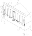
Figure 1 shows a perspective view of the back side of a supporting plate such as is part of the loading platform according to the invention, whereby this is turned upright relative to the bridge plate, in the rest position. -
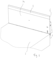
Figure 2 shows a perspective view of the front side of the supporting plate shown infigure 1 . also in the position wherein this stands upright. -
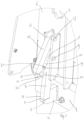
Figure 3 shows a perspective view of a detail of the back side of the supporting plate shown infigure 1 . -
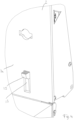
Figure 4 shows a perspective view of a detail of the front side of the supporting plate as shown infigure 2 . -
Figure 5a shows a side view in section of the supporting plate, in the position in which this stands upright. -
Figure 5b shows a side view in section of the supporting plate, in the position in which this stands upright, but wherein the foot has been pushed of the seat. -
Figure 5c shows a side view in section of the supporting plate, in a position in which this has been turned a length downwards. -
Figure 5d shows a side view in section of the supporting plate, in the position in which this lies horizontal or flat, and in which position the supporting plate can form a bridging between the loading platform and the loading floor of a vehicle that is to be loaded and unloaded. -
Figure 5e shows a side view in section of the supporting plate, in the position in which this has been turned a length upwards again. - In the
figures 1 ,2 and4 is shown a part of aloading platform 1. Theloading platform 1 comprises at the front side a supportingplate 2 provided rotatably. The supportingplate 2 can be turned from out of a rest position or upright position, in which the supportingplate 2 stands substantially upright (figures 1 ,2 ,3 4 ,5a and5b ) downwards into a lying position, in which the supportingplate 2 lies substantially horizontal or flat (figure 5d ) and in this way can form a bridging between theloading platform 1 and the loading floor of a vehicle that is to be loaded and unloaded (not shown in the figures). - There are provided interlocking means so that the supporting
plate 2. when this stands in the upright position, can be locked in that position, so that this does not unintentionally smack down and cause damage to persons. - As can be seen in the
figures 3 and5a . in this example of an embodiment, at thefront side 3 of the loading platform 1 abody 4 is provided with aseat 5. As can be seen in thefigures 1 ,3 and5a the supportingplate 2. as seen in the upright position of the supportingplate 2. is provided at the back side 6 with, in this example of an embodiment, a substantially rod shapedlocking part 7. As seen in the upright position of the supporting plate 1 (2). shown infigures 1 ,2 ,3 ,4 ,5a and5b , thelocking part 7 at its portion 8 above is suspended via afirst hinge point 9 on the supportingplate 2. From thisfirst hinge point 9 thelocking part 7 can make turning movement, running perpendicular to the plane of the back side 6 of the supportingplate 2. At itsportion 10 below thelocking part 7 is provided with afoot 11, by way of which thelocking part 7 can rest on theseat 5. In the drawings it can be seen that, when thelocking part 7 stands by itsfoot 11 on theseat 5, thelocking element 7, due to the attachment to the supportingplate 2 by way of thehinge point 9, prevents a turning downwards of the supporting plate. - In order to be able to turn the supporting plate 1(2) downwards it is necessary for the foot to go away from the
seat 5. To that end apedal 12 is formed on to thelocking part 7 at the portion 8 above. Thepedal 12 can be reached via thefront side 14 of the supportingplate 2 through anopening 13 provided in the supporting plate 2 (figures 2 ,4 ,5a ,5b ,5c ,5d ). When an operator pushes thepedal 12 downwards thelocking part 7 pivots around thefirst hinge point 9. With that thefoot 11 turns sideways and upwards away from the plane of the back side 6 of the supportingplate 2, and away from theseat 5. - If the pedal 4(12) were to be released again the
locking element 7 would, due to its weight, turn back again to its starting position along thehinge point 9. - In order to attain that the
locking part 7. as soon as thepedal 12 is released, will not immediately turn back again along thehinge point 9 and end up again with thefoot 11 on theseat 5, the supportingplate 2 is provided on the back side 6 with, in this example of an embodiment, a. substantially rod-shaped, holdingpart 15. As seen in the upright position of the supportingplate 2. the holding part, at anupper end 16, is suspended on the supportingplate 2 via asecond hinge point 17, located above thefirst hinge point 19. From out there theholding part 15 can make a turning movement running perpendicular to the plane of the back side 6 of the supportingplate 2. as can be seen infigure 5b . Theholding part 15 below has a first grippingpart 18, in this example of an embodiment ahook 18. As can be seen in thefigures 1 ,3 ,5a and5b , theholding part 15 hangs, in the upright position of the supportingplate 2, shown in thefigures 1 .3 and5a , partly against thelocking part 7. whereby thehook 18 lies on or hangs against aresting point 19 that is situated on amiddle part 20 of thelocking part 7. A length underneath thisresting point 19 thelocking part 7 is provided with a second grippingpart 21. in this example of an embodiment in the form of aprotruding part 21, that, in this example of an embodiment, as seen in de upright position of the supportingplate 2, runs downwards. - The first gripping
part 18 and the second grippingpart 21 work together as follows. - In
figure 5a is shown a side view in section of the supportingplate 2. in the position in which this stands upright. Thefoot 11 rests on theseat 5. Thehook 18 lies or hangs against theresting point 19 on themiddle part 20 of thelocking part 7.Figure 5b shows a same side view in section of the supporting plate, in the position in which this stands upright, but wherein thefoot pedal 12 has been pushed in and thelocking part 7 along thefirst hinge point 9 has been turned a length upwards, and whereby thefoot 11 has been turned away from theseat 5. With this turning upwards of thelocking part 7 theprotruding part 21 slides along thehook 18 on theholding part 15, whereby thebottom edge 23 of theprotruding part 21 at some moment passes thepoint 24 of the hook. Thereby thehook 18 eventually ends up in thespace 22 between theprotruding part 21 and themiddle part 20, and hooks fixedly therein. By means of this theholding part 15 holds thelocking part 7 in a position wherein this is partly turned upwards, and thelocking part 7 cannot turn back, and the foot cannot 11 end up on theseat 5. - An operator can now turn the supporting
plate 2 downwards in the lying position. - He thereby does not have to hold the pedal pushed in, because, as can be seen in
figure 5b , the lockingpart 7 at the location of thespace 22 between the protrudingpart 21 and themiddle part 20 is held by thehook 18. and therewith the lockingpart 7 is held in a partly upwards turned position. The lockingarm 7 cannot turn back, and the foot cannot end up back on theseat 5. - The supporting
plate 2 can now be turned downwards further by the operator, and, as can be seen infigure 5c , the holdingpart 15 thereby keeps on holding the lockingpart 7. so that thefoot 11 remains being turned away from theseat 5. Infigure 5d , that shows the supportingplate 2 in the position wherein this lies completely horizontal or flat, it can be seen that during the further turning downwards of the supportingplate 2 the lockingpart 7 along thefirst hinge point 9 and the holdingpart 15 along thesecond hinge point 17 turn further away from the plane of the back side 6 of the supportingplate 2. whereby these in the lying position of the supportingplate 2. underneath the supportingplate 2, because of their weight, hang straight downwards. - During the turning movement of the supporting
plate 2 downwards and during the turning of the lockingpart 7 and the holdingpart 15 along the hinge points 9 and 17. the locking part and the holding part because of their weight move away from each other. The distance between thefirst hinge point 9 and thesecond hinge point 17, the position of thehook 18 on the holdingpart 15 and the position of the protrudingpart 21 on the lockingpart 7. as well as the shape of thehook 18 and the protrudingpart 21, are adapted to each other, such that it is attained that during the turning movement downwards of the supportingplate 2 toward the lying position thehook 18 at some moment again falls out of thespace 22 between the protrudingpart 21 and themiddle part 20. - Now when the supporting
plate 2 out of the lying position is turned upwards again to the position upright, the lockingpart 7 and the holdingpart 15 again turn towards the plane of the back side 6 of the supportingplate 2. As can be seen infigure 5e with the movement upwards thehook 18 again comes to lie on or hang against theresting point 19 on themiddle portion 20 of the lockingpart 7 and so end up in the starting position shown infigures 1 ,3 and5a . Because thefood pedal 12 is not pushed in, and also because there is no question of the holding part keeping the locking part turned upwards, thefoot 11 can automatically end up on theseat 5. and the supportingplate 2 is locked again in the resting position. - 1. Loading platform
- 2. Supporting plate
- 3. Front side bridge plate
- 4. Body
- 5. Seat
- 6. Back side supporting plate
- 7. Locking part
- 8. Portion above of locking part
- 9. First hinge point
- 10. Portion underneath locking part
- 11. Foot
- 12. Pedal
- 13. Opening supporting plate
- 14. Front side supporting plate
- 15. Holding part
- 16. Upper end holding part
- 17. Second hinge point
- 18. First gripping part / hook
- 19. Resting point
- 20. Middle portion locking part
- 21. Second holding part / protruding part
- 22. Space
- 23. Bottom edge protruding part
- 24. Point of the hook
Claims (3)
- Loading platform with a supporting plate which at its loading platform side rotatably is connected to the loading platform and which from there along can be turned downwards from out of a rest position or upright position, in which the supporting plate stands substantially upright, into a lying position, in which the supporting plate lies substantially horizontal or flat and can form a bridging between the loading platform and the loading floor of a vehicle that is to be loaded and unloaded, with locking means for the locking of the supporting plate in the upright position, characterized in that the locking means are formed in that the loading platform is provided with a body with a seat, while the supporting plate is provided with a locking part that, as seen in the upright position of the supporting plate, at a portion above, through a first hinge point, is suspended on the supporting plate and from out there can make a turning movement running perpendicular to the plane of the supporting plate, while a portion below comprises a foot by means of which the locking part can rest on the seat, and by means of which a turning downwards of the supporting plate is held up, whereby an operating means is provided by which the foot can be turned off the seat and a turning downwards of the supporting plate no longer is prevented, whereby further means are provided by which, after the foot has been turned of the seat, it can be prevented that the foot turns back again on to the seat.
- Loading platform according to claim 1, characterized in that the means are formed in that the supporting plate is provided with a holding part that, as seen in the upright position of the part, at an upper end via a second hinge point, located above the first hinge point, is suspended on the supporting plate and from out there can make a turning movement running perpendicular to the plane of the supporting plate, and whereby the holding means at a portion below comprises a first gripping part by means of which, as seen in the upright position of the supporting plate, it lies on or hangs against a resting point that is provided onto a middle portion of the locking part, and whereby the middle part below the resting point is provided with a second gripping part, co-operating with the first gripping part, in such a way, that when the foot is turned from off the seat, the second gripping means ends up in a grip with the first gripping means and holds this secure.
- Loading platform according to claim 2. characterized in that the second gripping means is formed by, as seen in the upright position of the supporting plate, a downwards running protruding part, and the first gripping means is formed by a hook.
Applications Claiming Priority (1)
| Application Number | Priority Date | Filing Date | Title |
|---|---|---|---|
| NL2032140A NL2032140B1 (en) | 2022-06-13 | 2022-06-13 | Loading dock with lock. |
Publications (3)
| Publication Number | Publication Date |
|---|---|
| EP4292965A1 true EP4292965A1 (en) | 2023-12-20 |
| EP4292965C0 EP4292965C0 (en) | 2025-08-27 |
| EP4292965B1 EP4292965B1 (en) | 2025-08-27 |
Family
ID=87280469
Family Applications (1)
| Application Number | Title | Priority Date | Filing Date |
|---|---|---|---|
| EP23177569.3A Active EP4292965B1 (en) | 2022-06-13 | 2023-06-06 | Loading platform with interlock |
Country Status (3)
| Country | Link |
|---|---|
| EP (1) | EP4292965B1 (en) |
| NL (1) | NL2032140B1 (en) |
| PL (1) | PL4292965T3 (en) |
Citations (5)
| Publication number | Priority date | Publication date | Assignee | Title |
|---|---|---|---|---|
| US3460175A (en) * | 1967-08-02 | 1969-08-12 | Loomis Machine Co | Dockboard assembly |
| US4279050A (en) * | 1979-11-29 | 1981-07-21 | Overhead Door Corporation | Leg latch for in-pit dock levelers |
| US4865507A (en) * | 1988-05-05 | 1989-09-12 | Rite-Hite Corporation | Dock leveler assembly and latch mechanism therefor |
| US5117526A (en) * | 1990-05-03 | 1992-06-02 | The Serco Corporation | Vertically storing dock leveler |
| US7043790B2 (en) * | 2003-05-27 | 2006-05-16 | Spx Dock Products, Inc. | Vertically-storing dock leveler apparatus and method |
-
2022
- 2022-06-13 NL NL2032140A patent/NL2032140B1/en active
-
2023
- 2023-06-06 PL PL23177569.3T patent/PL4292965T3/en unknown
- 2023-06-06 EP EP23177569.3A patent/EP4292965B1/en active Active
Patent Citations (5)
| Publication number | Priority date | Publication date | Assignee | Title |
|---|---|---|---|---|
| US3460175A (en) * | 1967-08-02 | 1969-08-12 | Loomis Machine Co | Dockboard assembly |
| US4279050A (en) * | 1979-11-29 | 1981-07-21 | Overhead Door Corporation | Leg latch for in-pit dock levelers |
| US4865507A (en) * | 1988-05-05 | 1989-09-12 | Rite-Hite Corporation | Dock leveler assembly and latch mechanism therefor |
| US5117526A (en) * | 1990-05-03 | 1992-06-02 | The Serco Corporation | Vertically storing dock leveler |
| US7043790B2 (en) * | 2003-05-27 | 2006-05-16 | Spx Dock Products, Inc. | Vertically-storing dock leveler apparatus and method |
Also Published As
| Publication number | Publication date |
|---|---|
| EP4292965C0 (en) | 2025-08-27 |
| EP4292965B1 (en) | 2025-08-27 |
| NL2032140B1 (en) | 2023-12-20 |
| PL4292965T3 (en) | 2026-01-12 |
Similar Documents
| Publication | Publication Date | Title |
|---|---|---|
| US5845940A (en) | Fuel tank mount for forklift trucks with a damped swing arm swingable along a tilted arc | |
| US4098416A (en) | Carrier for compressed gas cylinders | |
| CN112173922A (en) | Elevator car with stable work platform | |
| GB2150427A (en) | Adjustable support apparatus | |
| US11759663B1 (en) | Bucket hook with tether hole | |
| US5746461A (en) | Bird feeder hanging device system | |
| EP0257925B1 (en) | Self-emptying container | |
| US4854807A (en) | Freight container lifting means | |
| EP4292965B1 (en) | Loading platform with interlock | |
| US4368874A (en) | Log lifter | |
| US5975495A (en) | Lift | |
| US4425985A (en) | Ladder platform | |
| US6883454B2 (en) | Watercraft roll-on system | |
| KR102326551B1 (en) | Footrest to Hang a String | |
| EP0319627A1 (en) | Freight container lifting means | |
| US5391040A (en) | Apparatus for handling boxes | |
| JP2011032700A (en) | Device for fixing step for ascent/descent | |
| US4119214A (en) | Method and device for loading stock into a machine | |
| KR200475895Y1 (en) | Folding for container stool ladder | |
| US4747736A (en) | Deck hanger for an intermodal container | |
| JPH0435513Y2 (en) | ||
| US20020029687A1 (en) | Device for forwarding large-caliber shells to a heavy weapon, especially in an armored howitzer | |
| US20240317560A1 (en) | Securing Assembly, Base, and Lifting Aid | |
| JP2657755B2 (en) | Truck tilt | |
| JPS5826188Y2 (en) | Loading platform opening/closing device in cargo handling lifting equipment |
Legal Events
| Date | Code | Title | Description |
|---|---|---|---|
| PUAI | Public reference made under article 153(3) epc to a published international application that has entered the european phase |
Free format text: ORIGINAL CODE: 0009012 |
|
| STAA | Information on the status of an ep patent application or granted ep patent |
Free format text: STATUS: THE APPLICATION HAS BEEN PUBLISHED |
|
| AK | Designated contracting states |
Kind code of ref document: A1 Designated state(s): AL AT BE BG CH CY CZ DE DK EE ES FI FR GB GR HR HU IE IS IT LI LT LU LV MC ME MK MT NL NO PL PT RO RS SE SI SK SM TR |
|
| STAA | Information on the status of an ep patent application or granted ep patent |
Free format text: STATUS: REQUEST FOR EXAMINATION WAS MADE |
|
| 17P | Request for examination filed |
Effective date: 20240617 |
|
| RBV | Designated contracting states (corrected) |
Designated state(s): AL AT BE BG CH CY CZ DE DK EE ES FI FR GB GR HR HU IE IS IT LI LT LU LV MC ME MK MT NL NO PL PT RO RS SE SI SK SM TR |
|
| GRAP | Despatch of communication of intention to grant a patent |
Free format text: ORIGINAL CODE: EPIDOSNIGR1 |
|
| STAA | Information on the status of an ep patent application or granted ep patent |
Free format text: STATUS: GRANT OF PATENT IS INTENDED |
|
| RIC1 | Information provided on ipc code assigned before grant |
Ipc: B65G 69/28 20060101AFI20241004BHEP |
|
| INTG | Intention to grant announced |
Effective date: 20241112 |
|
| GRAJ | Information related to disapproval of communication of intention to grant by the applicant or resumption of examination proceedings by the epo deleted |
Free format text: ORIGINAL CODE: EPIDOSDIGR1 |
|
| STAA | Information on the status of an ep patent application or granted ep patent |
Free format text: STATUS: REQUEST FOR EXAMINATION WAS MADE |
|
| GRAP | Despatch of communication of intention to grant a patent |
Free format text: ORIGINAL CODE: EPIDOSNIGR1 |
|
| STAA | Information on the status of an ep patent application or granted ep patent |
Free format text: STATUS: GRANT OF PATENT IS INTENDED |
|
| INTC | Intention to grant announced (deleted) | ||
| INTG | Intention to grant announced |
Effective date: 20250320 |
|
| GRAS | Grant fee paid |
Free format text: ORIGINAL CODE: EPIDOSNIGR3 |
|
| GRAA | (expected) grant |
Free format text: ORIGINAL CODE: 0009210 |
|
| STAA | Information on the status of an ep patent application or granted ep patent |
Free format text: STATUS: THE PATENT HAS BEEN GRANTED |
|
| AK | Designated contracting states |
Kind code of ref document: B1 Designated state(s): AL AT BE BG CH CY CZ DE DK EE ES FI FR GB GR HR HU IE IS IT LI LT LU LV MC ME MK MT NL NO PL PT RO RS SE SI SK SM TR |
|
| REG | Reference to a national code |
Ref country code: CH Ref legal event code: EP |
|
| REG | Reference to a national code |
Ref country code: DE Ref legal event code: R096 Ref document number: 602023006024 Country of ref document: DE |
|
| REG | Reference to a national code |
Ref country code: IE Ref legal event code: FG4D |
|
| U01 | Request for unitary effect filed |
Effective date: 20250828 |
|
| U07 | Unitary effect registered |
Designated state(s): AT BE BG DE DK EE FI FR IT LT LU LV MT NL PT RO SE SI Effective date: 20250904 |
|
| REG | Reference to a national code |
Ref country code: CH Ref legal event code: R17 Free format text: ST27 STATUS EVENT CODE: U-0-0-R10-R17 (AS PROVIDED BY THE NATIONAL OFFICE) Effective date: 20251017 |
|
| REG | Reference to a national code |
Ref country code: SK Ref legal event code: T3 Ref document number: E 47384 Country of ref document: SK |
|
| PG25 | Lapsed in a contracting state [announced via postgrant information from national office to epo] |
Ref country code: IS Free format text: LAPSE BECAUSE OF FAILURE TO SUBMIT A TRANSLATION OF THE DESCRIPTION OR TO PAY THE FEE WITHIN THE PRESCRIBED TIME-LIMIT Effective date: 20251227 |
|
| PG25 | Lapsed in a contracting state [announced via postgrant information from national office to epo] |
Ref country code: HR Free format text: LAPSE BECAUSE OF FAILURE TO SUBMIT A TRANSLATION OF THE DESCRIPTION OR TO PAY THE FEE WITHIN THE PRESCRIBED TIME-LIMIT Effective date: 20250827 |
|
| PG25 | Lapsed in a contracting state [announced via postgrant information from national office to epo] |
Ref country code: GR Free format text: LAPSE BECAUSE OF FAILURE TO SUBMIT A TRANSLATION OF THE DESCRIPTION OR TO PAY THE FEE WITHIN THE PRESCRIBED TIME-LIMIT Effective date: 20251128 |
|
| PG25 | Lapsed in a contracting state [announced via postgrant information from national office to epo] |
Ref country code: RS Free format text: LAPSE BECAUSE OF FAILURE TO SUBMIT A TRANSLATION OF THE DESCRIPTION OR TO PAY THE FEE WITHIN THE PRESCRIBED TIME-LIMIT Effective date: 20251127 |
|
| PG25 | Lapsed in a contracting state [announced via postgrant information from national office to epo] |
Ref country code: ES Free format text: LAPSE BECAUSE OF FAILURE TO SUBMIT A TRANSLATION OF THE DESCRIPTION OR TO PAY THE FEE WITHIN THE PRESCRIBED TIME-LIMIT Effective date: 20250827 |
|
| PG25 | Lapsed in a contracting state [announced via postgrant information from national office to epo] |
Ref country code: SM Free format text: LAPSE BECAUSE OF FAILURE TO SUBMIT A TRANSLATION OF THE DESCRIPTION OR TO PAY THE FEE WITHIN THE PRESCRIBED TIME-LIMIT Effective date: 20250827 |
|
| PGFP | Annual fee paid to national office [announced via postgrant information from national office to epo] |
Ref country code: PL Payment date: 20260327 Year of fee payment: 4 |
|
| PLBE | No opposition filed within time limit |
Free format text: ORIGINAL CODE: 0009261 |
|
| STAA | Information on the status of an ep patent application or granted ep patent |
Free format text: STATUS: NO OPPOSITION FILED WITHIN TIME LIMIT |
|
| REG | Reference to a national code |
Ref country code: CH Ref legal event code: L10 Free format text: ST27 STATUS EVENT CODE: U-0-0-L10-L00 (AS PROVIDED BY THE NATIONAL OFFICE) Effective date: 20260708 |
|
| U20 | Renewal fee for the european patent with unitary effect paid |
Year of fee payment: 4 Effective date: 20260601 |
|
| PGFP | Annual fee paid to national office [announced via postgrant information from national office to epo] |
Ref country code: NO Payment date: 20260619 Year of fee payment: 4 |
|
| REG | Reference to a national code |
Ref country code: CH Ref legal event code: U11 Free format text: ST27 STATUS EVENT CODE: U-0-0-U10-U11 (AS PROVIDED BY THE NATIONAL OFFICE) Effective date: 20260715 |
|
| PGFP | Annual fee paid to national office [announced via postgrant information from national office to epo] |
Ref country code: IE Payment date: 20260604 Year of fee payment: 4 |
|
| PGFP | Annual fee paid to national office [announced via postgrant information from national office to epo] |
Ref country code: CZ Payment date: 20260602 Year of fee payment: 4 |
|
| PGFP | Annual fee paid to national office [announced via postgrant information from national office to epo] |
Ref country code: SK Payment date: 20260604 Year of fee payment: 4 |
|
| 26N | No opposition filed |
Effective date: 20260528 |