EP4292931A1 - Movable area partition - Google Patents
Movable area partition Download PDFInfo
- Publication number
- EP4292931A1 EP4292931A1 EP23179417.3A EP23179417A EP4292931A1 EP 4292931 A1 EP4292931 A1 EP 4292931A1 EP 23179417 A EP23179417 A EP 23179417A EP 4292931 A1 EP4292931 A1 EP 4292931A1
- Authority
- EP
- European Patent Office
- Prior art keywords
- panel
- partition
- pivot point
- various embodiments
- movable
- Prior art date
- Legal status (The legal status is an assumption and is not a legal conclusion. Google has not performed a legal analysis and makes no representation as to the accuracy of the status listed.)
- Pending
Links
Images



Classifications
-
- B—PERFORMING OPERATIONS; TRANSPORTING
- B64—AIRCRAFT; AVIATION; COSMONAUTICS
- B64D—EQUIPMENT FOR FITTING IN OR TO AIRCRAFT; FLIGHT SUITS; PARACHUTES; ARRANGEMENT OR MOUNTING OF POWER PLANTS OR PROPULSION TRANSMISSIONS IN AIRCRAFT
- B64D11/00—Passenger or crew accommodation; Flight-deck installations not otherwise provided for
- B64D11/0023—Movable or removable cabin dividers, e.g. for class separation
-
- B—PERFORMING OPERATIONS; TRANSPORTING
- B64—AIRCRAFT; AVIATION; COSMONAUTICS
- B64D—EQUIPMENT FOR FITTING IN OR TO AIRCRAFT; FLIGHT SUITS; PARACHUTES; ARRANGEMENT OR MOUNTING OF POWER PLANTS OR PROPULSION TRANSMISSIONS IN AIRCRAFT
- B64D11/00—Passenger or crew accommodation; Flight-deck installations not otherwise provided for
- B64D11/04—Galleys
-
- B—PERFORMING OPERATIONS; TRANSPORTING
- B64—AIRCRAFT; AVIATION; COSMONAUTICS
- B64D—EQUIPMENT FOR FITTING IN OR TO AIRCRAFT; FLIGHT SUITS; PARACHUTES; ARRANGEMENT OR MOUNTING OF POWER PLANTS OR PROPULSION TRANSMISSIONS IN AIRCRAFT
- B64D11/00—Passenger or crew accommodation; Flight-deck installations not otherwise provided for
- B64D11/06—Arrangements of seats, or adaptations or details specially adapted for aircraft seats
- B64D11/0601—Arrangement of seats for non-standard seating layouts, e.g. seats staggered horizontally or vertically, arranged in an angled or fishbone layout, or facing in other directions than the direction of flight
Definitions
- the present disclosure generally relates to a movable area partition, and more specifically, to a movable area partition within an aircraft.
- aircraft interiors are divided into different areas including different types of seating and catering areas, or galleys.
- Larger aircraft such as wide body, twin aisle aircraft, generally have a galley between the two aisles and the between different sets of seating.
- Partitions are used to separate the seating areas from the galleys to provide a place for flight crew to work and to separate the galley from the seating areas.
- the distance between the seats and the partitions are regulated in part by head injury criteria established by the Federal Aviation Administration (FAA), among other agencies and organizations.
- the distance requirements specify clearance requirements between seating and partitions to reduce to likelihood of head injury or death in the event of an emergency.
- the distance requirements further provided different distances of taxi, take off, and landing than those during flight.
- a movable area partition is disclosed herein.
- the movable area partition includes a bottom pivot point, a top pivot point, a first panel having a first end and an opposing second end, the first end of the first panel pivotably coupled to the bottom pivot point, and a second panel having a first end an opposing second end, the first end of the second panel rotatably coupled to the second end of the first panel and the second end of the second panel pivotably coupled to the top pivot point.
- the first panel and the second panel rotate from a first position to a second position that is different than the first position.
- the movable area partition further includes a locking mechanism including an upper locking pin, the upper locking pin configured to extend from within the first panel and into the second panel to lock first panel and the second panel in a first position.
- the movable area partition further includes a third panel having a first end and an opposing second end, first end of the third panel rotatably coupled to the second end of the first panel and the second end of the third panel rotatably coupled to the first end of the second panel.
- the movable area partition further includes a locking mechanism including an upper locking pin and a lower locking pin, the locking mechanism disposed within the third panel, the upper locking pin configured to extend from the third panel into the second panel to lock the movable area partition in a first position.
- the lower locking pin is configured to extend from the third panel into the first panel to lock the movable area partition in a second position that is different than the first position.
- the third panel and the second panel are colinear when locked in the first position.
- an aircraft including a galley, a seat, and a movable partition disposed between the galley and the seat.
- the movable partition includes a bottom pivot point, a top pivot point, a first panel having a first end and an opposing second end, the first end coupled to the bottom pivot point, and a second panel having a first end and an opposing second end, the first end of the second panel coupled to the second end of the first panel, the second end of the second panel coupled to the top pivot point.
- the aircraft further includes a floor anchor, wherein the bottom pivot point is coupled to the floor anchor.
- the top pivot point is coupled to the ceiling anchor.
- the movable partition further includes a third panel disposed between the first panel and the second panel, the third panel coupled to the first panel and the second panel.
- the movable partition is configured to move to a first position, the second panel and the third panel being colinear in the first position.
- the movable partition is further configured to move from the first position to a second position, the first panel and the third panel being colinear in the second position.
- the aircraft further includes a locking mechanism disposed within the third panel where the locking mechanism includes an upper locking pin, a lower locking pin, and a rod connected to the upper locking pin at a first end and the lower locking pin at an opposing second end.
- the upper locking pin extends into the second panel in response to the rod moving in a first direction.
- the lower locking pin extends into the first panel in response to the rod moving in a second direction that is opposite the first direction.
- the locking mechanism further includes a handle configured to move the rod in the first direction and the second direction.
- the movable partition further includes a locking mechanism disposed within the middle panel, the locking mechanism including a first locking pin configured to extend from the middle panel into the top panel in response to the middle panel and the top panel being colinear.
- the locking mechanism further includes a second locking pin configured to extend from the middle panel into the bottom panel in response to the middle panel the bottom panel being colinear.
- references to "a,” “an” or “the” may include one or more than one and that reference to an item in the singular may also include the item in the plural. Further, all ranges may include upper and lower values and all ranges and ratio limits disclosed herein may be combined.
- the novel partitions disclosed herein use a series of panels that, when joined together, use rotational motion around pivots at each joint to move from a TTL position to an in-flight position in a way that the attachments to the aircraft remain stationary.
- the partition in various embodiments, may be moved from the TTL position to the in-flight position and back by releasing a latch and manually rotating the panels.
- the top two panels are colinear when in the TTL position and the bottom two panels are colinear when in the in-flight position.
- the partition when in the TTL position, satisfies regulatory head injury requirements set by different agencies, such as the Federal Aviation Administration (FAA).
- the partitions, when in the TTL position satisfy the larger distance requirements of the FAA, among others, while also satisfying the shorter distance requirements when placed in the in-flight position.
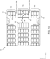
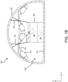
- FIGS. 1A and 1B in accordance with various embodiments, an aircraft interior 100 is illustrated.
- FIG. 1A illustrates on overhead view (e.g., the z-axis) of a seating arrangement, or layout of passenger accommodations, within aircraft interior 100.
- FIG. 1B illustrates a cross section view of aircraft interior 100.
- aircraft interior 100 includes seats 102, an aisle 103a, an aisle 103b, a cross aisle 104, a partition 106 separating seats 102, and cart storage 108.
- Seats 102 are placed in rows and sections with a first section 102a being between aisle 103a and an exterior wall 130 of an aircraft 120, second section 102b being between aisle 103a and aisle 103b, and a third section 102c being between aisle 103b and an exterior wall 132 of aircraft 120.
- Partition 106 is depicted as extending between aisle 103a and aisle 103b.
- another partition 106 in front of first section 102a and/or second section 102b.
- partition 106 may be placed in other locations of aircraft interior 100, such as between seats 102 and a bathroom, among others.
- Cart storage 108 may be part of an aircraft galley and located adjacent cross aisle 104.
- distance d2 there is a distance d2 between partition 106, or anything mounted on partition 106, and seats 102 (e.g., in the x-axis) and more specifically between partition 106 and a seat reference point (e.g., the back cushion of seat 102).
- a cushion reference point may be used, where the cushion reference point is the intersection of the back cushion and bottom cushion of seat 102.
- Distance d2 may be about 35 inches (88.9 cm) to about 50 inches (127.0 cm), and more specifically, about 35 inches (88.9 cm) to about 43 inches (109.2 cm) to meet regulatory distances.
- for safety distance d2 be at least 43 inches (109.2 cm) during TTL and at least 35 inches (88.9 cm) while in-flight, as measured by the seat reference point or the cushion reference point.
- a cross section (e.g., along the x-axis) of an aircraft 120 includes an airframe 122, aircraft interior 100, partition 106, a floor 110, overhead storage 112, a ceiling 114, and ceiling supports 116.
- Partition 106 is further depicted, in accordance with various embodiments, as including three panels, a top panel 106a, a middle panel 106b, and a bottom panel 106c. Partition 106 separates seats 102 from galley 104. In the depicted embodiment, partition 106 does not extend to ceiling 114, allowing access to overhead storage 112. In various embodiments, where overhead storage 112 is not present above partition 106, partition 106 may extend to ceiling 114.
- connector 208 may be a ball and socket join, a condyloid join, a saddle join, a hinge join, a pivot join, a knuckle joint, a clevis joint, or any other connection that allows top panel 202 to swing (e.g., in the x-axis) as it transitions from the TTL position to the in-flight position.
- Connector 210 connects top panel 202 to middle panel 204 allowing top panel 202 and middle panel 204 to rotate with respect to each other.
- connector 210 may be a hinge and pin, or piano hinge connector, among others.
- Connector 212 connects middle panel 204 to bottom panel 206 allowing middle panel 204 and bottom panel 206 to rotate with respect to each other.
- TTL head strike arc 220 does not contact movable partition 200 in the TTL position because movable partition 200 is moved outside of TTL head strike arc 220 during TTL.
- top panel 202 and middle panel 204 are colinear while middle panel 204 and bottom panel 206 are not colinear. That is, there is a straight line between connector 208 and connector 212 through top panel 202 and middle panel 204 and middle panel 204 is at an angle with respect to bottom panel 206.
- movable partition 200 reduces the amount of available space in cross aisle 104 while increasing the amount of available space in front of seat 102.
- Top panel 202 has a length L1, middle panel 204 has a length L2, and bottom panel 206 has a length L3.
- Length L1 may be about 6 inches (15.2 cm) to about 24 inches (60.9 cm).
- Length L2 may be about 12 inches (30.5 cm) to about 48 inches (121.9 cm).
- Length L3 may be about 12 inches (30.5 cm) to about 36 inches (91.4 cm).
- the length of each panel, 202, 204, 206 is variable based on the desired design and aesthetic of movable partition 200. When top panel 202, middle panel 204, and/or bottom panel 206 are curved the lengths of each panel are more configurable and may be outside the ranges previously mentioned. While various examples are provided above, it should be understood that the dimensions of movable partition 200 are highly configurable and may be larger or smaller than those provided above in various installations.
- Movable partition 200 may be moved from the TTL position to the in-flight position manually, mechanically, or electrically using a motor.
- top panel 202, middle panel 204, and bottom panel 206 may move and/or rotate independently of each other.
- movable partition 200 includes a locking mechanism to secure movable partition 200 in either the TTL position or the in-flight position.
- Locking mechanism include upper locking pins 302, lower locking pins 304, a connector rod 306, and a handle 308.
- Handle 308 may be used to manually operate locking mechanism 300.
- handle 308 may be a knob, a wheel, or other rotational mechanism.
- locking mechanism 300 may be operated by a motor or other mechanical means and handle 308 may be removed.
- Upper locking pins 302, lower locking pins 304, and connector rod 306 may be made from metal, plastic, composite, or other materials.
- Upper locking pins 302, lower locking pins 304, and connector rod 306 may be tubes, rods, pins, or other structures.
- upper locking pins 302 and lower locking pins 304 may be actuated using one or more solenoids without the use of connector rod 306. In various embodiments, other configurations including more locking pins are contemplated.
- middle panel 204 may be hollow providing space for locking mechanism 300.
- middle panel 204 may be solid and include a space therein that allows for travel of connector rod 306, upper locking pins 302, and lower locking pins 304.
- Top panel 202 and bottom panel 206 may include holes that receive upper locking pins 302 and lower locking pins 304, respectively.
- upper locking pins 302 extend upward (e.g., the z-direction) from within middle panel 204 and into top panel 202
- lower locking pins 304 are retracted upward (e.g., the z-direction) from bottom panel 206 and into middle panel 204, and handle 308 is in an up position.
- upper locking pins 302 are retracted downward (e.g., the negative z-direction) from top panel 202 and into middle panel 204, lower locking pins 304 extend downward (e.g., the negative z-direction) and into bottom panel 206, and handle 308 is in a down position.
- Locking mechanism 300 further includes pivot points 310 for upper locking pins 302, pivot points 312 for lower locking pins 304, and a pivot point 314 for handle 308.
- Handle 308 pivots about pivot point 314 when moving from the up position to the down position.
- Upper locking pins 302 pivot about pivot points 310 when extending and retracting.
- Lower locking pins 304 pivot about pivot points 312 when extending and retracting.
- handle 308 is in a neutral position (e.g., horizontal in the y-axis)
- upper locking pins 302 are retracted downward (e.g., the negative z-direction) and lower locking pins 304 are retracted upward (e.g., the z-direction). This allows movable partition 200 to move freely between the TTL position and the in-flight position.
- Partition 400 may be an example of partition 106 described above with respect to FIG. 1A .
- Partition 400 includes similar components to those described above with respect to movable partition 200 in FIGS. 2A and 2B including connector 208, connector 214, top panel 402, and bottom panel 404. As such, components that are similar between movable partition 200 and partition 400 may not be described again below.
- Partition 400 may further include a locking mechanism similar to locking mechanism 300 including upper locking pins 302. FIG.
- Partition 400 includes two panels (e.g., top panel 402 and bottom panel 404) instead of the three panels of movable partition 200.
- Connector 210 connects top panel 402 to bottom panel 404, as previously described with respect to movable partition 200.
- Top panel 402 has a length L4 that is about 8 inches (20.3 cm) to about 36 inches (91.4 cm).
- Bottom panel 404 has a length L5 that is about 24 inches (60.9 cm) to about 60 inches (152.4 cm). While top panel 402 and bottom panel 404 are depicted as being straight, in various embodiment top panel 402 and/or bottom panel 404 may be curved or have another shape.
- bottom panel 404 may additionally include an outer portion and an inner portion configured to slide with respect to the outer portion. That is, the inner portion may extend from the outer portion and retract into the outer portion. In this way, bottom panel 404 may extend to be longer or retract to be shorter depending on the angle between top panel 402 and bottom panel 404.
- Partition 500 may be an example of partition 106 described above with respect to FIG. 1A .
- Partition 500 includes similar components to those described above with respect to movable partition 200 in FIGS. 2A and 2B including connector 208, connector 214, top panel 502, and bottom panel 504. As such, components that are similar between movable partition 200 and partition 500 may not be described again below.
- Partition 500 may further include a locking mechanism similar to locking mechanism 300 including upper locking pins 302. FIG.
- FIG. 5A illustrates a side view of partition 500 in the taxi, take off, and landing (TTL) position, including TTL head strike arc 220 and in-flight limiting arc 222.
- FIG. 5B illustrates a side view of partition 500 in the in-flight position including TTL head strike arc 220 and in-flight limiting arc 222.
- Partition 500 includes two panels (e.g., top panel 502 and bottom panel 504) instead of the three panels of movable partition 200.
- Connector 210 connects top panel 502 to bottom panel 504, as previously described with respect to movable partition 200.
- Top panel 502 has a length L6 that is about 24 inches (60.9 cm) to about 48 inches (121.9 cm).
- Bottom panel 504 has a length L7 that is about 24 inches (60.9 cm) to about 48 inches (121.9 cm). While top panel 502 and bottom panel 504 are depicted as being straight, in various embodiment top panel 502 and/or bottom panel 504 may be curved or have another shape.
- references to "one embodiment,” “an embodiment,” “various embodiments,” etc. indicate that the embodiment described may include a particular feature, structure, or characteristic, but every embodiment may not necessarily include the particular feature, structure, or characteristic. Moreover, such phrases are not necessarily referring to the same embodiment. Further, when a particular feature, structure, or characteristic is described in connection with an embodiment, it is submitted that it is within the knowledge of one skilled in the art to affect such feature, structure, or characteristic in connection with other embodiments whether or not explicitly described. After reading the description, it will be apparent to one skilled in the relevant art(s) how to implement the disclosure in alternative embodiments.
Landscapes
- Engineering & Computer Science (AREA)
- Aviation & Aerospace Engineering (AREA)
- Aiming, Guidance, Guns With A Light Source, Armor, Camouflage, And Targets (AREA)
- Seats For Vehicles (AREA)
Abstract
Description
- The present disclosure generally relates to a movable area partition, and more specifically, to a movable area partition within an aircraft.
- Generally, aircraft interiors are divided into different areas including different types of seating and catering areas, or galleys. Larger aircraft, such as wide body, twin aisle aircraft, generally have a galley between the two aisles and the between different sets of seating. Partitions are used to separate the seating areas from the galleys to provide a place for flight crew to work and to separate the galley from the seating areas. The distance between the seats and the partitions are regulated in part by head injury criteria established by the Federal Aviation Administration (FAA), among other agencies and organizations. The distance requirements specify clearance requirements between seating and partitions to reduce to likelihood of head injury or death in the event of an emergency. The distance requirements further provided different distances of taxi, take off, and landing than those during flight.
- A movable area partition is disclosed herein. The movable area partition includes a bottom pivot point, a top pivot point, a first panel having a first end and an opposing second end, the first end of the first panel pivotably coupled to the bottom pivot point, and a second panel having a first end an opposing second end, the first end of the second panel rotatably coupled to the second end of the first panel and the second end of the second panel pivotably coupled to the top pivot point.
- In various embodiments, the first panel and the second panel rotate from a first position to a second position that is different than the first position. In various embodiments, the movable area partition further includes a locking mechanism including an upper locking pin, the upper locking pin configured to extend from within the first panel and into the second panel to lock first panel and the second panel in a first position.
- In various embodiments, the movable area partition further includes a third panel having a first end and an opposing second end, first end of the third panel rotatably coupled to the second end of the first panel and the second end of the third panel rotatably coupled to the first end of the second panel. In various embodiments, the movable area partition further includes a locking mechanism including an upper locking pin and a lower locking pin, the locking mechanism disposed within the third panel, the upper locking pin configured to extend from the third panel into the second panel to lock the movable area partition in a first position. In various embodiments, the lower locking pin is configured to extend from the third panel into the first panel to lock the movable area partition in a second position that is different than the first position. In various embodiments, the third panel and the second panel are colinear when locked in the first position.
- Also disclosed herein is an aircraft including a galley, a seat, and a movable partition disposed between the galley and the seat. The movable partition includes a bottom pivot point, a top pivot point, a first panel having a first end and an opposing second end, the first end coupled to the bottom pivot point, and a second panel having a first end and an opposing second end, the first end of the second panel coupled to the second end of the first panel, the second end of the second panel coupled to the top pivot point.
- In various embodiments, the aircraft further includes a floor anchor, wherein the bottom pivot point is coupled to the floor anchor. In various embodiments, the top pivot point is coupled to the ceiling anchor. In various embodiments, the movable partition further includes a third panel disposed between the first panel and the second panel, the third panel coupled to the first panel and the second panel. In various embodiments, the movable partition is configured to move to a first position, the second panel and the third panel being colinear in the first position.
- In various embodiments, the movable partition is further configured to move from the first position to a second position, the first panel and the third panel being colinear in the second position. In various embodiments, the aircraft further includes a locking mechanism disposed within the third panel where the locking mechanism includes an upper locking pin, a lower locking pin, and a rod connected to the upper locking pin at a first end and the lower locking pin at an opposing second end. In various embodiments, the upper locking pin extends into the second panel in response to the rod moving in a first direction. In various embodiments, the lower locking pin extends into the first panel in response to the rod moving in a second direction that is opposite the first direction. In various embodiments, the locking mechanism further includes a handle configured to move the rod in the first direction and the second direction.
- Also disclosed herein is a movable partition including a bottom panel pivotable about a bottom pivot point, a top panel pivotable about a top pivot point, and a middle panel having a first end and an opposing second end, the first end of the middle panel rotatably coupled to the bottom panel and the second end of the middle panel rotatably coupled to the top panel.
- In various embodiments, the movable partition further includes a locking mechanism disposed within the middle panel, the locking mechanism including a first locking pin configured to extend from the middle panel into the top panel in response to the middle panel and the top panel being colinear. In various embodiments, the locking mechanism further includes a second locking pin configured to extend from the middle panel into the bottom panel in response to the middle panel the bottom panel being colinear.
- The foregoing features and elements may be combined in any combination, without exclusivity, unless expressly indicated herein otherwise. These features and elements as well as the operation of the disclosed embodiments will become more apparent in light of the following description and accompanying drawings.
- The subject matter of the present disclosure is particularly pointed out and distinctly claimed in the concluding portion of the specification. A more complete understanding of the present disclosure, however, may best be obtained by referring to the following detailed description and claims in connection with the following drawings. While the drawings illustrate various embodiments employing the principles described herein, the drawings do not limit the scope of the claims.
-
FIGS. 1A and1B illustrate an aircraft interior layout, in accordance with various embodiments. -
FIGS. 2A and2B illustrate a movable area partition, in accordance with various embodiments. -
FIGS. 3A and3B illustrate a locking mechanism used with a movable area partition, in accordance with various embodiments. -
FIGS. 4A and4B illustrate a movable area partition, in accordance with various embodiments. -
FIGS. 5A and5B illustrate a movable area partition, in accordance with various embodiments. - The following detailed description of various embodiments herein makes reference to the accompanying drawings, which show various embodiments by way of illustration. While these various embodiments are described in sufficient detail to enable those skilled in the art to practice the disclosure, it should be understood that other embodiments may be realized and that changes may be made without departing from the scope of the disclosure. Thus, the detailed description herein is presented for purposes of illustration only and not of limitation. Furthermore, any reference to singular includes plural embodiments, and any reference to more than one component or step may include a singular embodiment or step. Also, any reference to attached, fixed, connected, or the like may include permanent, removable, temporary, partial, full or any other possible attachment option. Additionally, any reference to without contact (or similar phrases) may also include reduced contact or minimal contact. It should also be understood that unless specifically stated otherwise, references to "a," "an" or "the" may include one or more than one and that reference to an item in the singular may also include the item in the plural. Further, all ranges may include upper and lower values and all ranges and ratio limits disclosed herein may be combined.
- Disclosed herein is a moving partition that intrudes into a galley, or similar area, during taxi, take off, and landing (TTL), but can be repositioned to an in-flight mode that restores the cart ingress/egress space and catering space during flight operations. The use of the movable partition, in various embodiments, provides about 7 inches (17.8 cm) to about 8 inches (20.3 cm) additional space within the aircraft cabin. The additional space may be used, in various embodiments, to provide additional leg space for each seat, to upgrade to larger seating, or to move seating closer to the galley, among other configurations that may be used as part of an overall aircraft cabin optimization effort.
- The novel partitions disclosed herein, in various embodiments, use a series of panels that, when joined together, use rotational motion around pivots at each joint to move from a TTL position to an in-flight position in a way that the attachments to the aircraft remain stationary. The partition, in various embodiments, may be moved from the TTL position to the in-flight position and back by releasing a latch and manually rotating the panels. In various embodiments, the top two panels are colinear when in the TTL position and the bottom two panels are colinear when in the in-flight position. The partition, when in the TTL position, satisfies regulatory head injury requirements set by different agencies, such as the Federal Aviation Administration (FAA). The partitions, when in the TTL position, satisfy the larger distance requirements of the FAA, among others, while also satisfying the shorter distance requirements when placed in the in-flight position.
- Additionally or in the alternative, the partition are attached to the floor of the aircraft and overhead. In various embodiments, the partition may move from the TTL position to the in-flight position, and back, by pivoting about the floor attachment and the overhead attachment. In various embodiments, the top attachment may translate laterally along a track and/or pivot about an intermediate hinge to meet head injury criteria clearances.
- Referring now to
FIGS. 1A and1B , in accordance with various embodiments, anaircraft interior 100 is illustrated.FIG. 1A illustrates on overhead view (e.g., the z-axis) of a seating arrangement, or layout of passenger accommodations, withinaircraft interior 100.FIG. 1B illustrates a cross section view ofaircraft interior 100. - As depicted in
FIG. 1A ,aircraft interior 100 includesseats 102, anaisle 103a, anaisle 103b, across aisle 104, apartition 106 separatingseats 102, andcart storage 108.Seats 102 are placed in rows and sections with afirst section 102a being betweenaisle 103a and anexterior wall 130 of anaircraft 120,second section 102b being betweenaisle 103a andaisle 103b, and athird section 102c being betweenaisle 103b and anexterior wall 132 ofaircraft 120.Partition 106 is depicted as extending betweenaisle 103a andaisle 103b. In various embodiments, anotherpartition 106 in front offirst section 102a and/orsecond section 102b. In various embodiments,partition 106 may be placed in other locations ofaircraft interior 100, such as betweenseats 102 and a bathroom, among others.Cart storage 108 may be part of an aircraft galley and locatedadjacent cross aisle 104. - There is a distance d1 between
cart storage 108 and partition 106 (e.g., in the x-axis). Inconventional aircraft interior 100, distance d1 is about 37 inches (94 cm) to about 40 inches (101.6 cm). However, distance d1 may be about 20 inches (50.8 cm) to about 40 inches (101.6 cm). In various embodiments, distance d1 may be larger or smaller.Aircraft interior 100 may provide for a minimum of 20 inches (50.8 cm) during taxi, take off, and landing (TTL) and a minimum of 35 inches (88.9 cm) while in-flight to allow a full size cart to be extracted fromcart storage 108. In various embodiments,different aircraft interiors 100 may have different minimum distances for distance d1 based on the type of cart used (e.g., full size cart, half-size cart, stacked carts, etc.) Whenpartition 106, as disclosed herein in various embodiments, is used, distance d1 may be about 29 inches (73.6 cm) to about 32 inches (81.3 cm) during TTL. A distance of about 35 inches (88.9 cm) to about 40 inches (101.6 cm) may be used to remove a catering cart fromcart storage 108. There is a distance d2 betweenpartition 106, or anything mounted onpartition 106, and seats 102 (e.g., in the x-axis) and more specifically betweenpartition 106 and a seat reference point (e.g., the back cushion of seat 102). In various embodiments, a cushion reference point may be used, where the cushion reference point is the intersection of the back cushion and bottom cushion ofseat 102. Distance d2 may be about 35 inches (88.9 cm) to about 50 inches (127.0 cm), and more specifically, about 35 inches (88.9 cm) to about 43 inches (109.2 cm) to meet regulatory distances. For example, for safety distance d2 be at least 43 inches (109.2 cm) during TTL and at least 35 inches (88.9 cm) while in-flight, as measured by the seat reference point or the cushion reference point. - As depicted in
FIG. 1B , a cross section (e.g., along the x-axis) of anaircraft 120 includes anairframe 122,aircraft interior 100,partition 106, afloor 110,overhead storage 112, aceiling 114, and ceiling supports 116.Partition 106 is further depicted, in accordance with various embodiments, as including three panels, atop panel 106a, amiddle panel 106b, and abottom panel 106c.Partition 106separates seats 102 fromgalley 104. In the depicted embodiment,partition 106 does not extend toceiling 114, allowing access tooverhead storage 112. In various embodiments, whereoverhead storage 112 is not present abovepartition 106,partition 106 may extend toceiling 114.Top panel 106a may be pivotably coupled to ceiling supports 116 suing partition supports 118. Partition supports 118 provide a stable upper support forpartition 106 and can be bolted to any height withinaircraft 120. Generally, ceiling supports 116 are present inaircraft 120 for attaching interior features such asceiling 114,overhead storage 112, among others. Couplingpartition 106 to already existing ceiling supports 116 provides an easier path to retrofitaircraft 120 to includepartition 106.Bottom panel 106c may be pivotably coupled tofloor 110, providing a stable lower support forpartition 106. Generally, floor attachments are present inaircraft 120 and may include seat tracks for installingseats 102 or other anchors for attaching interior furnishings toaircraft interior 100. In various embodiments, magazine holders, inflight entertainment (e.g., tv screens), or other amenities may be mounted topartition 106. - Referring now to
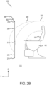
FIGS. 2A and2B , in accordance with various embodiments, amovable partition 200 is illustrated.Movable partition 200 may be an example ofpartition 106 described above with respect toFIGS. 1A and1B .FIG. 2A illustrates a side view ofmovable partition 200 in the taxi, take off, and landing (TTL) position andFIG. 2B illustrates a side view ofmovable partition 200 in the in-flight position. -
Movable partition 200 includes three panels, atop panel 202, amiddle panel 204, and abottom panel 206.Movable partition 200 further includes aconnector 208, a connector 210 aconnector 212, and aconnector 214.Connector 208 connectstop panel 202 toaircraft 120, and more specifically, to partition supports 118. In various embodiments,connector 208 provides a pivot point about whichtop panel 202 may pivot, or swing, as it transitions from the TTL position to the inflight position. Invarious embodiments connector 208 may be a ball and socket join, a condyloid join, a saddle join, a hinge join, a pivot join, a knuckle joint, a clevis joint, or any other connection that allowstop panel 202 to swing (e.g., in the x-axis) as it transitions from the TTL position to the in-flight position.Connector 210 connectstop panel 202 tomiddle panel 204 allowingtop panel 202 andmiddle panel 204 to rotate with respect to each other. In various embodiments,connector 210 may be a hinge and pin, or piano hinge connector, among others.Connector 212 connectsmiddle panel 204 tobottom panel 206 allowingmiddle panel 204 andbottom panel 206 to rotate with respect to each other.Connector 212 may be the same type of connector asconnector 210.Connector 214 connectsbottom panel 206 tofloor 110 ofaircraft 120.Connector 212 provides a stable connection point about withbottom panel 206 can rotate, pivot, or swing (e.g., in the x-axis). In the illustrated embodiment,connector 208 is longitudinally offset (e.g., in the x-direction) with respect toconnector 214 such thatconnector 208 andconnector 214 are not in the same vertical (e.g., in the z-axis) plane. In various embodiments, the longitudinal offset betweenconnector 208 andconnector 214 may be about 3 inches (7.6 cm) to about 10 inches (25.4 cm). In various embodiments,connector 208 is not longitudinally offset with respect to connector 214 (e.g., they are in the same vertical plane (e.g., the z-axis). -
FIG. 2A further includes TTLhead strike arc 220 and in-flight limiting arc 222. Inflight limiting arc 222 defines an arc within which components must be delethalized, or in other words, not be fatal to a passenger should the passenger's head collide with the component while in flight. TTLhead strike arc 220 illustrates the regulatory distance of a passenger's head betweenseat 102 andmovable partition 200 during TTL. This may be an example of distance d2 during TTL described above with respect toFIG. 1A . TTLhead strike arc 220 may be about 43 inches (109.2 cm) from the seat reference point (SRP) (e.g., a backrest 230) ofseat 102. TTLhead strike arc 220 may be based on the 50th percentile height and may be referred as the 50th percentile head strike arc. In-flight limiting arc 222 may be about 35 inches (88.9 cm) from backrest (CRP)230, or a cushion reference point, ofseat 102. The cushion reference point ofseat 102 is the intersection ofbackrest 230 and bottom, or seat cushion, ofseat 102. To meet regulatory requirements, TTLhead strike arc 220 may not contactmovable partition 200, or anything mounted tomovable partition 200, during TTL and in-flight limiting arc 222 may not contactmovable partition 200, or anything mounted tomovable partition 200, while in flight. More specifically, in-flight limiting arc 222 is a delethalization arc, that is, should a passenger hitmovable partition 200, or a component mounted tomovable partition 200, the passenger should not suffer significant injury from the impact. - In the depicted embodiment of
FIG. 2A , TTLhead strike arc 220 does not contactmovable partition 200 in the TTL position becausemovable partition 200 is moved outside of TTLhead strike arc 220 during TTL. As illustrated, when moved outside of TTLhead strike arc 220 for TTL,top panel 202 andmiddle panel 204 are colinear whilemiddle panel 204 andbottom panel 206 are not colinear. That is, there is a straight line betweenconnector 208 andconnector 212 throughtop panel 202 andmiddle panel 204 andmiddle panel 204 is at an angle with respect tobottom panel 206. When in the TTL position,movable partition 200 reduces the amount of available space incross aisle 104 while increasing the amount of available space in front ofseat 102. - Referring now to
FIG. 2B ,movable partition 200 is illustrated in the in-flight position, according to various embodiments. Whenmovable partition 200 is in the in-flight position, TTLhead strike arc 220 may contactmovable partition 200. However, in-flight limiting arc 222 does not contactmovable partition 200. In the in-flight position, as depicted,middle panel 204 andbottom panel 206 are colinear whiletop panel 202 andmiddle panel 204 are not colinear. In various embodiments,middle panel 204 andbottom panel 206 may not be colinear in the in-flight position. That is, there is a straight line betweenconnector 210 andconnector 214 throughmiddle panel 204 andbottom panel 206 andtop panel 202 is at an angle with respect tomiddle panel 204. When in the in-flight position,movable partition 200 increases the amount of available space ingalley 104 while reducing the amount of available space in front ofseat 102. - In the depicted embodiment of
FIGS. 2A and2B ,top panel 202,middle panel 204, andbottom panel 206 are straight panels, that is, extending in a straight line between each connection point. In various embodiments, one or more oftop panel 202,middle panel 204, andbottom panel 206 may include a curve, be curved, include multiple angled faces, or otherwise manufactured to include an orientation other than straight. Straight, flat panels are more economical to manufacture and easier to install. However, any shape or feature is possible to be included on one or more oftop panel 202,middle panel 204, andbottom panel 206 so long as the regulatory distance for the TTL position and in-flight position are met. -
Top panel 202 has a length L1,middle panel 204 has a length L2, andbottom panel 206 has a length L3. Length L1 may be about 6 inches (15.2 cm) to about 24 inches (60.9 cm). Length L2 may be about 12 inches (30.5 cm) to about 48 inches (121.9 cm). Length L3 may be about 12 inches (30.5 cm) to about 36 inches (91.4 cm). The length of each panel, 202, 204, 206, is variable based on the desired design and aesthetic ofmovable partition 200. Whentop panel 202,middle panel 204, and/orbottom panel 206 are curved the lengths of each panel are more configurable and may be outside the ranges previously mentioned. While various examples are provided above, it should be understood that the dimensions ofmovable partition 200 are highly configurable and may be larger or smaller than those provided above in various installations. -
Movable partition 200 may be moved from the TTL position to the in-flight position manually, mechanically, or electrically using a motor. When moving between the TTL position and the in-flight position,top panel 202,middle panel 204, andbottom panel 206 may move and/or rotate independently of each other. In various embodiments,movable partition 200 includes a locking mechanism to securemovable partition 200 in either the TTL position or the in-flight position. - Referring now to
FIGS. 3A and3B , in accordance with various embodiments, alocking mechanism 300 is illustrated with respect tomovable partition 200.FIG. 3A is a perspective view ofmovable partition 200 in the taxi, take off, and landing (TTL) position andlocking mechanism 300 in a TTL locked position.FIG. 3B is a perspective viewmovable partition 200 in the in-flight position and locking mechanism in an in-flight locked position.Locking mechanism 300 is internal tomovable partition 200 but for simplicity and ease ofdiscussion locking mechanism 300 is depicted as solid lines. - Locking mechanism include upper locking pins 302, lower locking pins 304, a
connector rod 306, and ahandle 308. Handle 308 may be used to manually operatelocking mechanism 300. In various embodiments, handle 308 may be a knob, a wheel, or other rotational mechanism. In various embodiments,locking mechanism 300 may be operated by a motor or other mechanical means and handle 308 may be removed. Upper locking pins 302, lower locking pins 304, andconnector rod 306 may be made from metal, plastic, composite, or other materials. Upper locking pins 302, lower locking pins 304, andconnector rod 306 may be tubes, rods, pins, or other structures. In various embodiments, upper locking pins 302 and lower locking pins 304 may be actuated using one or more solenoids without the use ofconnector rod 306. In various embodiments, other configurations including more locking pins are contemplated. - In various embodiments,
middle panel 204 may be hollow providing space for lockingmechanism 300. In various embodiments,middle panel 204 may be solid and include a space therein that allows for travel ofconnector rod 306, upper locking pins 302, and lower locking pins 304.Top panel 202 andbottom panel 206 may include holes that receive upper locking pins 302 and lower locking pins 304, respectively. When locking mechanism is in the TTL locked position, as illustrated inFIG. 3A , upper locking pins 302 extend upward (e.g., the z-direction) from withinmiddle panel 204 and intotop panel 202, lower locking pins 304 are retracted upward (e.g., the z-direction) frombottom panel 206 and intomiddle panel 204, and handle 308 is in an up position. When locking mechanism is in the in-flight locked position, as illustrated inFIG. 3B , upper locking pins 302 are retracted downward (e.g., the negative z-direction) fromtop panel 202 and intomiddle panel 204, lower locking pins 304 extend downward (e.g., the negative z-direction) and intobottom panel 206, and handle 308 is in a down position. -
Locking mechanism 300 further includes pivot points 310 for upper locking pins 302, pivot points 312 for lower locking pins 304, and apivot point 314 forhandle 308. Handle 308 pivots aboutpivot point 314 when moving from the up position to the down position. Upper locking pins 302 pivot about pivot points 310 when extending and retracting. Lower locking pins 304 pivot about pivot points 312 when extending and retracting. When handle 308 is in a neutral position (e.g., horizontal in the y-axis), upper locking pins 302 are retracted downward (e.g., the negative z-direction) and lower locking pins 304 are retracted upward (e.g., the z-direction). This allowsmovable partition 200 to move freely between the TTL position and the in-flight position. - Referring now to
FIGS. 4A and4B , in accordance with various embodiments, amovable partition 400 is illustrated.Partition 400 may be an example ofpartition 106 described above with respect toFIG. 1A .Partition 400 includes similar components to those described above with respect tomovable partition 200 inFIGS. 2A and2B including connector 208,connector 214,top panel 402, andbottom panel 404. As such, components that are similar betweenmovable partition 200 andpartition 400 may not be described again below.Partition 400 may further include a locking mechanism similar tolocking mechanism 300 including upper locking pins 302.FIG. 4A illustrates a side view ofpartition 400 in the taxi, take off, and landing (TTL) position, including TTLhead strike arc 220 and in-flight limiting arc 222.FIG. 4B illustrates a side view ofpartition 400 in the in-flight position including TTLhead strike arc 220 and in-flight limiting arc 222. -
Partition 400 includes two panels (e.g.,top panel 402 and bottom panel 404) instead of the three panels ofmovable partition 200.Connector 210 connectstop panel 402 tobottom panel 404, as previously described with respect tomovable partition 200.Top panel 402 has a length L4 that is about 8 inches (20.3 cm) to about 36 inches (91.4 cm).Bottom panel 404 has a length L5 that is about 24 inches (60.9 cm) to about 60 inches (152.4 cm). Whiletop panel 402 andbottom panel 404 are depicted as being straight, in various embodimenttop panel 402 and/orbottom panel 404 may be curved or have another shape. Whenpartition 400 is in the TTL position, there is enough room betweenpartition 400 andseat 102 to accommodate TTLhead strike arc 220 according to regulations. Whenpartition 400 is in the in-flight position, there is enough room betweenpartition 400 andseat 102 to accommodate in-flight limiting arc 222 according to regulations. - In various embodiments,
bottom panel 404 may additionally include an outer portion and an inner portion configured to slide with respect to the outer portion. That is, the inner portion may extend from the outer portion and retract into the outer portion. In this way,bottom panel 404 may extend to be longer or retract to be shorter depending on the angle betweentop panel 402 andbottom panel 404. - Referring now to
FIGS. 5A and5B , in accordance with various embodiments, amovable partition 500 is illustrated.Partition 500 may be an example ofpartition 106 described above with respect toFIG. 1A .Partition 500 includes similar components to those described above with respect tomovable partition 200 inFIGS. 2A and2B including connector 208,connector 214,top panel 502, andbottom panel 504. As such, components that are similar betweenmovable partition 200 andpartition 500 may not be described again below.Partition 500 may further include a locking mechanism similar tolocking mechanism 300 including upper locking pins 302.FIG. 5A illustrates a side view ofpartition 500 in the taxi, take off, and landing (TTL) position, including TTLhead strike arc 220 and in-flight limiting arc 222.FIG. 5B illustrates a side view ofpartition 500 in the in-flight position including TTLhead strike arc 220 and in-flight limiting arc 222. -
Partition 500 includes two panels (e.g.,top panel 502 and bottom panel 504) instead of the three panels ofmovable partition 200.Connector 210 connectstop panel 502 tobottom panel 504, as previously described with respect tomovable partition 200.Top panel 502 has a length L6 that is about 24 inches (60.9 cm) to about 48 inches (121.9 cm).Bottom panel 504 has a length L7 that is about 24 inches (60.9 cm) to about 48 inches (121.9 cm). Whiletop panel 502 andbottom panel 504 are depicted as being straight, in various embodimenttop panel 502 and/orbottom panel 504 may be curved or have another shape. Whenpartition 500 is in the TTL position, there is enough room betweenpartition 500 andseat 102 to accommodate TTLhead strike arc 220 according to regulations. Whenpartition 500 is in the in-flight position, there is enough room betweenpartition 500 andseat 102 to accommodate in-flight limiting arc 222 according to regulations. - Benefits, other advantages, and solutions to problems have been described herein with regard to specific embodiments. Furthermore, the connecting lines shown in the various figures contained herein are intended to represent exemplary functional relationships and/or physical couplings between the various elements. It should be noted that many alternative or additional functional relationships or physical connections may be present in a practical system. However, the benefits, advantages, solutions to problems, and any elements that may cause any benefit, advantage, or solution to occur or become more pronounced are not to be construed as critical, required, or essential features or elements of the disclosure. The scope of the disclosure is accordingly to be limited by nothing other than the appended claims, in which reference to an element in the singular is not intended to mean "one and only one" unless explicitly so stated, but rather "one or more." Moreover, where a phrase similar to "at least one of A, B, or C" is used in the claims, it is intended that the phrase be interpreted to mean that A alone may be present in an embodiment, B alone may be present in an embodiment, C alone may be present in an embodiment, or that any combination of the elements A, B and C may be present in a single embodiment; for example, A and B, A and C, B and C, or A and B and C. Different cross-hatching is used throughout the figures to denote different parts but not necessarily to denote the same or different materials.
- Systems, methods and apparatus are provided herein. In the detailed description herein, references to "one embodiment," "an embodiment," "various embodiments," etc., indicate that the embodiment described may include a particular feature, structure, or characteristic, but every embodiment may not necessarily include the particular feature, structure, or characteristic. Moreover, such phrases are not necessarily referring to the same embodiment. Further, when a particular feature, structure, or characteristic is described in connection with an embodiment, it is submitted that it is within the knowledge of one skilled in the art to affect such feature, structure, or characteristic in connection with other embodiments whether or not explicitly described. After reading the description, it will be apparent to one skilled in the relevant art(s) how to implement the disclosure in alternative embodiments.
- Numbers, percentages, or other values stated herein are intended to include that value, and also other values that are about or approximately equal to the stated value, as would be appreciated by one of ordinary skill in the art encompassed by various embodiments of the present disclosure. A stated value should therefore be interpreted broadly enough to encompass values that are at least close enough to the stated value to perform a desired function or achieve a desired result. The stated values include at least the variation to be expected in a suitable industrial process, and may include values that are within 10%, within 5%, within 1%, within 0.1%, or within 0.01% of a stated value. Additionally, the terms "substantially," "about" or "approximately" as used herein represent an amount close to the stated amount that still performs a desired function or achieves a desired result. For example, the term "substantially," "about" or "approximately" may refer to an amount that is within 10% of, within 5% of, within 1% of, within 0.1% of, and within 0.01% of a stated amount or value.
- Furthermore, no element, component, or method step in the present disclosure is intended to be dedicated to the public regardless of whether the element, component, or method step is explicitly recited in the claims. As used herein, the terms "comprises," "comprising," or any other variation thereof, are intended to cover a non-exclusive inclusion, such that a process, method, article, or apparatus that comprises a list of elements does not include only those elements but may include other elements not expressly listed or inherent to such process, method, article, or apparatus.
- Finally, it should be understood that any of the above described concepts can be used alone or in combination with any or all of the other above described concepts. Although various embodiments have been disclosed and described, one of ordinary skill in this art would recognize that certain modifications would come within the scope of this disclosure. Accordingly, the description is not intended to be exhaustive or to limit the principles described or illustrated herein to any precise form. Many modifications and variations are possible in light of the above teaching.
Claims (15)
- A movable area partition, comprising:a bottom pivot point;a top pivot point;a first panel (206) having a first end and an opposing second end, the first end of the first panel pivotably coupled to the bottom pivot point; anda second panel (202) having a first end an opposing second end, the first end of the second panel rotatably coupled to the second end of the first panel and the second end of the second panel pivotably coupled to the top pivot point.
- The movable area partition of claim 1, wherein the first panel (206) and the second panel (202) rotate from a first position to a second position that is different than the first position.
- The movable area partition of claim 1 or 2, further comprising:
a locking mechanism including an upper locking pin (302), the upper locking pin configured to extend from within the first panel (206) and into the second panel (202) to lock first panel and the second panel in a first position. - The movable area partition of any preceding claim, further comprising:
a third panel (204) having a first end and an opposing second end, first end of the third panel rotatably coupled to the second end of the first panel and the second end of the third panel rotatably coupled to the first end of the second panel. - The movable area partition of claim 4, further comprising:
a locking mechanism including an upper locking pin (302) and a lower locking pin (304), the locking mechanism disposed within the third panel (204), the upper locking pin configured to extend from the third panel into the second panel to lock the movable area partition in a first position. - The movable area partition of claim 5, wherein the lower locking pin (304) is configured to extend from the third panel into the first panel to lock the movable area partition in a second position that is different than the first position; and/or
wherein the third panel and the second panel are colinear when locked in the first position. - An aircraft, comprising:a galley;a seat; anda movable partition disposed between the galley and the seat, the movable partition including:a bottom pivot point;a top pivot point;a first panel (206) having a first end and an opposing second end, the first end coupled to the bottom pivot point; anda second panel (202) having a first end and an opposing second end, the first end of the second panel coupled to the second end of the first panel, the second end of the second panel coupled to the top pivot point.
- The aircraft of claim 7, further comprising:
a floor anchor, wherein the bottom pivot point is coupled to the floor anchor. - The aircraft of claim 7 or 8, a ceiling anchor, wherein the top pivot point is coupled to the ceiling anchor.
- The aircraft of any of claims 7-9, wherein the movable partition further comprises:
a third panel (204) disposed between the first panel and the second panel, the third panel coupled to the first panel and the second panel. - The aircraft of claim 10, wherein the movable partition is configured to move to a first position, the second panel and the third panel being colinear in the first position, and preferably wherein the movable partition is further configured to move from the first position to a second position, the first panel and the third panel being colinear in the second position.
- The aircraft of claim 10 or 11, further comprising:
a locking mechanism disposed within the third panel, the locking mechanism including:an upper locking pin (302);a lower locking pin (304); anda rod (306) connected to the upper locking pin at a first end and the lower locking pin at an opposing second end. - The aircraft of claim 12, wherein the upper locking pin (302) extends into the second panel in response to the rod (306) moving in a first direction, and preferably wherein the lower locking pin (304) extends into the first panel in response to the rod (306) moving in a second direction that is opposite the first direction, and more preferably wherein the locking mechanism further includes a handle (308) configured to move the rod in the first direction and the second direction.
- A movable partition, comprising:a bottom panel (206) pivotable about a bottom pivot point;a top panel (202) pivotable about a top pivot point; anda middle panel (204) having a first end and an opposing second end, the first end of the middle panel rotatably coupled to the bottom panel and the second end of the middle panel rotatably coupled to the top panel.
- The movable partition of claim 14, further comprising:
a locking mechanism disposed within the middle panel, the locking mechanism including a first locking pin configured to extend from the middle panel into the top panel in response to the middle panel and the top panel being colinear, and preferably wherein the locking mechanism further includes a second locking pin configured to extend from the middle panel into the bottom panel in response to the middle panel the bottom panel being colinear.
Applications Claiming Priority (1)
| Application Number | Priority Date | Filing Date | Title |
|---|---|---|---|
| US17/843,525 US12103686B2 (en) | 2022-06-17 | 2022-06-17 | Movable area partition |
Publications (1)
| Publication Number | Publication Date |
|---|---|
| EP4292931A1 true EP4292931A1 (en) | 2023-12-20 |
Family
ID=86851830
Family Applications (1)
| Application Number | Title | Priority Date | Filing Date |
|---|---|---|---|
| EP23179417.3A Pending EP4292931A1 (en) | 2022-06-17 | 2023-06-15 | Movable area partition |
Country Status (2)
| Country | Link |
|---|---|
| US (1) | US12103686B2 (en) |
| EP (1) | EP4292931A1 (en) |
Citations (6)
| Publication number | Priority date | Publication date | Assignee | Title |
|---|---|---|---|---|
| WO1993001088A1 (en) * | 1991-07-06 | 1993-01-21 | Magerik Limited | Aircraft cabin divider |
| US5509700A (en) * | 1994-06-06 | 1996-04-23 | National Security Containers, Inc. | Latch and lock for trailer doors |
| DE10322611B3 (en) * | 2003-05-20 | 2004-08-12 | Daimlerchrysler Ag | Partition wall for automobile e.g. van, dividing load space from driving cab with hinged sections allowing parallel configuration at rear of adjustable passenger seat |
| EP1106502B1 (en) * | 1999-12-09 | 2006-03-08 | The Boeing Company | Foldable partition with integral door |
| US20170267353A1 (en) * | 2016-03-18 | 2017-09-21 | The Boeing Company | Deployable clearance panel system, method, and assembly for a monument within an internal cabin of an aircraft |
| WO2019068028A1 (en) * | 2017-09-29 | 2019-04-04 | B/E Aerospace, Inc. | Contoured class divider |
Family Cites Families (19)
| Publication number | Priority date | Publication date | Assignee | Title |
|---|---|---|---|---|
| US2274216A (en) * | 1941-02-11 | 1942-02-24 | Claude K Sanders | Door assembly |
| US2396039A (en) * | 1941-11-10 | 1946-03-05 | Douglas Aircraft Co Inc | Aircraft interior |
| US2868407A (en) * | 1956-01-12 | 1959-01-13 | Ti Group Services Ltd | Packing containers |
| GB1127435A (en) * | 1965-09-13 | 1968-09-18 | Henry John Kennard | Improvements in collapsible rectangular-side units such as containers for goods transport |
| US3423121A (en) * | 1967-02-10 | 1969-01-21 | Martin Lipkin | Protective partition against deceleration |
| US3768855A (en) * | 1972-08-28 | 1973-10-30 | J Laue | Collapsible and expandable enclosure |
| CA1196361A (en) * | 1984-04-30 | 1985-11-05 | Joseph Ledenyi | Partition shield for automobile interior |
| FR2614926B1 (en) * | 1987-05-07 | 1992-02-28 | Caillet Rene | LOW-DIMENSIONAL CURTAIN FOR CLOSING CROSSINGS |
| US5110164A (en) * | 1991-09-27 | 1992-05-05 | Morgan Trailer Mfg. Co. | Latching apparatus for a panel door |
| US5371982A (en) * | 1992-06-08 | 1994-12-13 | Hopkins International, Inc. | Portable area security enclosure kit |
| DE19605907B4 (en) * | 1996-02-17 | 2005-11-03 | Bos Gmbh & Co. Kg | Safety device for an interior of a motor vehicle |
| US20030127562A1 (en) * | 2002-01-07 | 2003-07-10 | Pereira Edson J. | Security partition system for prevention of hijackings |
| US8857496B2 (en) * | 2007-10-09 | 2014-10-14 | First Principles, Inc. | Configurable and interlocking partitioning device, method, and system of use thereof |
| FR2941917B1 (en) | 2009-02-11 | 2012-08-31 | Airbus | MODULAR CLOSURE DEVICE FOR AN AIRCRAFT |
| DE102014110820A1 (en) | 2014-07-30 | 2016-02-04 | Airbus Operations Gmbh | Seat assembly in a cabin of an aircraft and aircraft with a cabin and a seat assembly integrated therein |
| DE102014115462A1 (en) * | 2014-10-23 | 2016-04-28 | Airbus Operations Gmbh | Arrangement with a separation device in a cabin of a vehicle and aircraft with a cabin and such an arrangement |
| DE102016215405A1 (en) * | 2016-08-17 | 2018-02-22 | Ford Global Technologies, Llc | Device and method for subdividing cabins and / or holds, in particular of vehicles, into a number of subsections |
| EP3541654B1 (en) * | 2016-11-15 | 2023-08-16 | Safran Seats USA LLC | Mini suite emergency egress solutions |
| EP4144641B1 (en) * | 2021-09-02 | 2025-03-26 | B/E Aerospace, Inc. | Equipment for use in galleys in vessels |
-
2022
- 2022-06-17 US US17/843,525 patent/US12103686B2/en active Active
-
2023
- 2023-06-15 EP EP23179417.3A patent/EP4292931A1/en active Pending
Patent Citations (6)
| Publication number | Priority date | Publication date | Assignee | Title |
|---|---|---|---|---|
| WO1993001088A1 (en) * | 1991-07-06 | 1993-01-21 | Magerik Limited | Aircraft cabin divider |
| US5509700A (en) * | 1994-06-06 | 1996-04-23 | National Security Containers, Inc. | Latch and lock for trailer doors |
| EP1106502B1 (en) * | 1999-12-09 | 2006-03-08 | The Boeing Company | Foldable partition with integral door |
| DE10322611B3 (en) * | 2003-05-20 | 2004-08-12 | Daimlerchrysler Ag | Partition wall for automobile e.g. van, dividing load space from driving cab with hinged sections allowing parallel configuration at rear of adjustable passenger seat |
| US20170267353A1 (en) * | 2016-03-18 | 2017-09-21 | The Boeing Company | Deployable clearance panel system, method, and assembly for a monument within an internal cabin of an aircraft |
| WO2019068028A1 (en) * | 2017-09-29 | 2019-04-04 | B/E Aerospace, Inc. | Contoured class divider |
Also Published As
| Publication number | Publication date |
|---|---|
| US20230406506A1 (en) | 2023-12-21 |
| US12103686B2 (en) | 2024-10-01 |
Similar Documents
| Publication | Publication Date | Title |
|---|---|---|
| US10336455B2 (en) | Deployable clearance panel system, method, and assembly for a monument within an internal cabin of an aircraft | |
| CN104144854B (en) | toilet building components | |
| EP0850834B2 (en) | Fully reclinable, pivotable airplane passenger sleeper seat assemblies | |
| EP3333077B1 (en) | Modular cabin segment, cabin for a vehicle and vehicle with a cabin | |
| US10231563B2 (en) | Integrated curtain system and method | |
| EP3156331B1 (en) | Deployable door-mounted seat | |
| EP2796371B1 (en) | Cabin attendant seat with additional support | |
| US10737788B2 (en) | Systems and methods for adaptively positioning a cross-aisle curtain header assembly within a vehicle | |
| EP3939886B1 (en) | Contoured class divider | |
| US11465747B2 (en) | Overhead support platform system for a vehicle | |
| EP4582338A1 (en) | Bi-fold barrier system and method for a flight deck of an aircraft | |
| CN115432187A (en) | Rest area system for interior cabins of vehicles | |
| US10259586B2 (en) | Deployable seat assembly, system, and method for an interior cabin of a vehicle | |
| US12103686B2 (en) | Movable area partition | |
| US12071244B2 (en) | Reconfigurable seat assembly | |
| EP4461647A1 (en) | Wheelchair accessible airliner lavatory | |
| US11572177B2 (en) | Seat cable adjustment system and method | |
| BRPI0616203A2 (en) | Vertically Movable Passage for Ceiling Rest Areas and Method for Variable Passage Floor Height Configuration | |
| EP4112470A1 (en) | Emergency oxygen systems for internal cabins of aircraft | |
| US11945588B2 (en) | Stowage bin assemblies for and a method for increasing overhead space and configurability in an internal cabin of a vehicle | |
| US11377215B1 (en) | Stowable flight attendant seat system | |
| US12559237B2 (en) | Combination monument having lavatory and galley for an internal cabin of an aircraft | |
| US20240253789A1 (en) | Transformable seat systems and methods for an internal cabin of an aircraft | |
| US20240351691A1 (en) | Seating systems for internal cabins of aircraft |
Legal Events
| Date | Code | Title | Description |
|---|---|---|---|
| PUAI | Public reference made under article 153(3) epc to a published international application that has entered the european phase |
Free format text: ORIGINAL CODE: 0009012 |
|
| STAA | Information on the status of an ep patent application or granted ep patent |
Free format text: STATUS: THE APPLICATION HAS BEEN PUBLISHED |
|
| AK | Designated contracting states |
Kind code of ref document: A1 Designated state(s): AL AT BE BG CH CY CZ DE DK EE ES FI FR GB GR HR HU IE IS IT LI LT LU LV MC ME MK MT NL NO PL PT RO RS SE SI SK SM TR |
|
| STAA | Information on the status of an ep patent application or granted ep patent |
Free format text: STATUS: REQUEST FOR EXAMINATION WAS MADE |
|
| 17P | Request for examination filed |
Effective date: 20240618 |
|
| RBV | Designated contracting states (corrected) |
Designated state(s): AL AT BE BG CH CY CZ DE DK EE ES FI FR GB GR HR HU IE IS IT LI LT LU LV MC ME MK MT NL NO PL PT RO RS SE SI SK SM TR |
|
| STAA | Information on the status of an ep patent application or granted ep patent |
Free format text: STATUS: EXAMINATION IS IN PROGRESS |
|
| 17Q | First examination report despatched |
Effective date: 20250128 |
|
| GRAP | Despatch of communication of intention to grant a patent |
Free format text: ORIGINAL CODE: EPIDOSNIGR1 |
|
| STAA | Information on the status of an ep patent application or granted ep patent |
Free format text: STATUS: GRANT OF PATENT IS INTENDED |
|
| INTG | Intention to grant announced |
Effective date: 20251103 |
|
| GRAJ | Information related to disapproval of communication of intention to grant by the applicant or resumption of examination proceedings by the epo deleted |
Free format text: ORIGINAL CODE: EPIDOSDIGR1 |
|
| STAA | Information on the status of an ep patent application or granted ep patent |
Free format text: STATUS: EXAMINATION IS IN PROGRESS |
|
| GRAP | Despatch of communication of intention to grant a patent |
Free format text: ORIGINAL CODE: EPIDOSNIGR1 |
|
| STAA | Information on the status of an ep patent application or granted ep patent |
Free format text: STATUS: GRANT OF PATENT IS INTENDED |
|
| INTC | Intention to grant announced (deleted) | ||
| INTG | Intention to grant announced |
Effective date: 20260316 |