EP4292930A1 - Method and control system for controlling a wired vehicle fleet - Google Patents
Method and control system for controlling a wired vehicle fleet Download PDFInfo
- Publication number
- EP4292930A1 EP4292930A1 EP23172490.7A EP23172490A EP4292930A1 EP 4292930 A1 EP4292930 A1 EP 4292930A1 EP 23172490 A EP23172490 A EP 23172490A EP 4292930 A1 EP4292930 A1 EP 4292930A1
- Authority
- EP
- European Patent Office
- Prior art keywords
- connection element
- vehicle
- bendable connection
- wayline
- supply unit
- Prior art date
- Legal status (The legal status is an assumption and is not a legal conclusion. Google has not performed a legal analysis and makes no representation as to the accuracy of the status listed.)
- Pending
Links
Images




Classifications
-
- G—PHYSICS
- G05—CONTROLLING; REGULATING
- G05D—SYSTEMS FOR CONTROLLING OR REGULATING NON-ELECTRIC VARIABLES
- G05D1/00—Control of position, course, altitude or attitude of land, water, air or space vehicles, e.g. using automatic pilots
- G05D1/02—Control of position or course in two dimensions
- G05D1/021—Control of position or course in two dimensions specially adapted to land vehicles
- G05D1/0287—Control of position or course in two dimensions specially adapted to land vehicles involving a plurality of land vehicles, e.g. fleet or convoy travelling
- G05D1/0289—Control of position or course in two dimensions specially adapted to land vehicles involving a plurality of land vehicles, e.g. fleet or convoy travelling with means for avoiding collisions between vehicles
-
- B—PERFORMING OPERATIONS; TRANSPORTING
- B60—VEHICLES IN GENERAL
- B60L—PROPULSION OF ELECTRICALLY-PROPELLED VEHICLES; SUPPLYING ELECTRIC POWER FOR AUXILIARY EQUIPMENT OF ELECTRICALLY-PROPELLED VEHICLES; ELECTRODYNAMIC BRAKE SYSTEMS FOR VEHICLES IN GENERAL; MAGNETIC SUSPENSION OR LEVITATION FOR VEHICLES; MONITORING OPERATING VARIABLES OF ELECTRICALLY-PROPELLED VEHICLES; ELECTRIC SAFETY DEVICES FOR ELECTRICALLY-PROPELLED VEHICLES
- B60L1/00—Supplying electric power to auxiliary equipment of vehicles
- B60L1/003—Supplying electric power to auxiliary equipment of vehicles to auxiliary motors, e.g. for pumps, compressors
-
- B—PERFORMING OPERATIONS; TRANSPORTING
- B60—VEHICLES IN GENERAL
- B60L—PROPULSION OF ELECTRICALLY-PROPELLED VEHICLES; SUPPLYING ELECTRIC POWER FOR AUXILIARY EQUIPMENT OF ELECTRICALLY-PROPELLED VEHICLES; ELECTRODYNAMIC BRAKE SYSTEMS FOR VEHICLES IN GENERAL; MAGNETIC SUSPENSION OR LEVITATION FOR VEHICLES; MONITORING OPERATING VARIABLES OF ELECTRICALLY-PROPELLED VEHICLES; ELECTRIC SAFETY DEVICES FOR ELECTRICALLY-PROPELLED VEHICLES
- B60L3/00—Electric devices on electrically-propelled vehicles for safety purposes; Monitoring operating variables, e.g. speed, deceleration or energy consumption
- B60L3/0023—Detecting, eliminating, remedying or compensating for drive train abnormalities, e.g. failures within the drive train
-
- B—PERFORMING OPERATIONS; TRANSPORTING
- B60—VEHICLES IN GENERAL
- B60L—PROPULSION OF ELECTRICALLY-PROPELLED VEHICLES; SUPPLYING ELECTRIC POWER FOR AUXILIARY EQUIPMENT OF ELECTRICALLY-PROPELLED VEHICLES; ELECTRODYNAMIC BRAKE SYSTEMS FOR VEHICLES IN GENERAL; MAGNETIC SUSPENSION OR LEVITATION FOR VEHICLES; MONITORING OPERATING VARIABLES OF ELECTRICALLY-PROPELLED VEHICLES; ELECTRIC SAFETY DEVICES FOR ELECTRICALLY-PROPELLED VEHICLES
- B60L9/00—Electric propulsion with power supply external to the vehicle
-
- B—PERFORMING OPERATIONS; TRANSPORTING
- B64—AIRCRAFT; AVIATION; COSMONAUTICS
- B64U—UNMANNED AERIAL VEHICLES [UAV]; EQUIPMENT THEREFOR
- B64U10/00—Type of UAV
- B64U10/60—Tethered aircraft
-
- B—PERFORMING OPERATIONS; TRANSPORTING
- B65—CONVEYING; PACKING; STORING; HANDLING THIN OR FILAMENTARY MATERIAL
- B65H—HANDLING THIN OR FILAMENTARY MATERIAL, e.g. SHEETS, WEBS, CABLES
- B65H75/00—Storing webs, tapes, or filamentary material, e.g. on reels
- B65H75/02—Cores, formers, supports, or holders for coiled, wound, or folded material, e.g. reels, spindles, bobbins, cop tubes, cans, mandrels or chucks
- B65H75/34—Cores, formers, supports, or holders for coiled, wound, or folded material, e.g. reels, spindles, bobbins, cop tubes, cans, mandrels or chucks specially adapted or mounted for storing and repeatedly paying-out and re-storing lengths of material provided for particular purposes, e.g. anchored hoses, power cables
- B65H75/38—Cores, formers, supports, or holders for coiled, wound, or folded material, e.g. reels, spindles, bobbins, cop tubes, cans, mandrels or chucks specially adapted or mounted for storing and repeatedly paying-out and re-storing lengths of material provided for particular purposes, e.g. anchored hoses, power cables involving the use of a core or former internal to, and supporting, a stored package of material
- B65H75/40—Cores, formers, supports, or holders for coiled, wound, or folded material, e.g. reels, spindles, bobbins, cop tubes, cans, mandrels or chucks specially adapted or mounted for storing and repeatedly paying-out and re-storing lengths of material provided for particular purposes, e.g. anchored hoses, power cables involving the use of a core or former internal to, and supporting, a stored package of material mobile or transportable
- B65H75/42—Cores, formers, supports, or holders for coiled, wound, or folded material, e.g. reels, spindles, bobbins, cop tubes, cans, mandrels or chucks specially adapted or mounted for storing and repeatedly paying-out and re-storing lengths of material provided for particular purposes, e.g. anchored hoses, power cables involving the use of a core or former internal to, and supporting, a stored package of material mobile or transportable attached to, or forming part of, mobile tools, machines or vehicles
- B65H75/425—Cores, formers, supports, or holders for coiled, wound, or folded material, e.g. reels, spindles, bobbins, cop tubes, cans, mandrels or chucks specially adapted or mounted for storing and repeatedly paying-out and re-storing lengths of material provided for particular purposes, e.g. anchored hoses, power cables involving the use of a core or former internal to, and supporting, a stored package of material mobile or transportable attached to, or forming part of, mobile tools, machines or vehicles attached to, or forming part of a vehicle, e.g. truck, trailer, vessel
-
- G—PHYSICS
- G05—CONTROLLING; REGULATING
- G05D—SYSTEMS FOR CONTROLLING OR REGULATING NON-ELECTRIC VARIABLES
- G05D1/00—Control of position, course, altitude or attitude of land, water, air or space vehicles, e.g. using automatic pilots
- G05D1/02—Control of position or course in two dimensions
- G05D1/021—Control of position or course in two dimensions specially adapted to land vehicles
- G05D1/0212—Control of position or course in two dimensions specially adapted to land vehicles with means for defining a desired trajectory
- G05D1/0214—Control of position or course in two dimensions specially adapted to land vehicles with means for defining a desired trajectory in accordance with safety or protection criteria, e.g. avoiding hazardous areas
-
- G—PHYSICS
- G05—CONTROLLING; REGULATING
- G05D—SYSTEMS FOR CONTROLLING OR REGULATING NON-ELECTRIC VARIABLES
- G05D1/00—Control of position, course, altitude or attitude of land, water, air or space vehicles, e.g. using automatic pilots
- G05D1/02—Control of position or course in two dimensions
- G05D1/021—Control of position or course in two dimensions specially adapted to land vehicles
- G05D1/0287—Control of position or course in two dimensions specially adapted to land vehicles involving a plurality of land vehicles, e.g. fleet or convoy travelling
- G05D1/0291—Fleet control
-
- H—ELECTRICITY
- H02—GENERATION; CONVERSION OR DISTRIBUTION OF ELECTRIC POWER
- H02G—INSTALLATION OF ELECTRIC CABLES OR LINES, OR OF COMBINED OPTICAL AND ELECTRIC CABLES OR LINES
- H02G11/00—Arrangements of electric cables or lines between relatively-movable parts
- H02G11/006—Arrangements of electric cables or lines between relatively-movable parts using extensible carrier for the cable, e.g. self-coiling spring
-
- A—HUMAN NECESSITIES
- A01—AGRICULTURE; FORESTRY; ANIMAL HUSBANDRY; HUNTING; TRAPPING; FISHING
- A01B—SOIL WORKING IN AGRICULTURE OR FORESTRY; PARTS, DETAILS, OR ACCESSORIES OF AGRICULTURAL MACHINES OR IMPLEMENTS, IN GENERAL
- A01B76/00—Parts, details or accessories of agricultural machines or implements, not provided for in groups A01B51/00 - A01B75/00
-
- B—PERFORMING OPERATIONS; TRANSPORTING
- B60—VEHICLES IN GENERAL
- B60L—PROPULSION OF ELECTRICALLY-PROPELLED VEHICLES; SUPPLYING ELECTRIC POWER FOR AUXILIARY EQUIPMENT OF ELECTRICALLY-PROPELLED VEHICLES; ELECTRODYNAMIC BRAKE SYSTEMS FOR VEHICLES IN GENERAL; MAGNETIC SUSPENSION OR LEVITATION FOR VEHICLES; MONITORING OPERATING VARIABLES OF ELECTRICALLY-PROPELLED VEHICLES; ELECTRIC SAFETY DEVICES FOR ELECTRICALLY-PROPELLED VEHICLES
- B60L2200/00—Type of vehicles
- B60L2200/10—Air crafts
-
- B—PERFORMING OPERATIONS; TRANSPORTING
- B60—VEHICLES IN GENERAL
- B60L—PROPULSION OF ELECTRICALLY-PROPELLED VEHICLES; SUPPLYING ELECTRIC POWER FOR AUXILIARY EQUIPMENT OF ELECTRICALLY-PROPELLED VEHICLES; ELECTRODYNAMIC BRAKE SYSTEMS FOR VEHICLES IN GENERAL; MAGNETIC SUSPENSION OR LEVITATION FOR VEHICLES; MONITORING OPERATING VARIABLES OF ELECTRICALLY-PROPELLED VEHICLES; ELECTRIC SAFETY DEVICES FOR ELECTRICALLY-PROPELLED VEHICLES
- B60L2200/00—Type of vehicles
- B60L2200/40—Working vehicles
-
- B—PERFORMING OPERATIONS; TRANSPORTING
- B60—VEHICLES IN GENERAL
- B60L—PROPULSION OF ELECTRICALLY-PROPELLED VEHICLES; SUPPLYING ELECTRIC POWER FOR AUXILIARY EQUIPMENT OF ELECTRICALLY-PROPELLED VEHICLES; ELECTRODYNAMIC BRAKE SYSTEMS FOR VEHICLES IN GENERAL; MAGNETIC SUSPENSION OR LEVITATION FOR VEHICLES; MONITORING OPERATING VARIABLES OF ELECTRICALLY-PROPELLED VEHICLES; ELECTRIC SAFETY DEVICES FOR ELECTRICALLY-PROPELLED VEHICLES
- B60L2260/00—Operating Modes
- B60L2260/20—Drive modes; Transition between modes
- B60L2260/32—Auto pilot mode
-
- B—PERFORMING OPERATIONS; TRANSPORTING
- B60—VEHICLES IN GENERAL
- B60L—PROPULSION OF ELECTRICALLY-PROPELLED VEHICLES; SUPPLYING ELECTRIC POWER FOR AUXILIARY EQUIPMENT OF ELECTRICALLY-PROPELLED VEHICLES; ELECTRODYNAMIC BRAKE SYSTEMS FOR VEHICLES IN GENERAL; MAGNETIC SUSPENSION OR LEVITATION FOR VEHICLES; MONITORING OPERATING VARIABLES OF ELECTRICALLY-PROPELLED VEHICLES; ELECTRIC SAFETY DEVICES FOR ELECTRICALLY-PROPELLED VEHICLES
- B60L2260/00—Operating Modes
- B60L2260/40—Control modes
- B60L2260/44—Control modes by parameter estimation
-
- B—PERFORMING OPERATIONS; TRANSPORTING
- B64—AIRCRAFT; AVIATION; COSMONAUTICS
- B64U—UNMANNED AERIAL VEHICLES [UAV]; EQUIPMENT THEREFOR
- B64U2101/00—UAVs specially adapted for particular uses or applications
- B64U2101/40—UAVs specially adapted for particular uses or applications for agriculture or forestry operations
-
- B—PERFORMING OPERATIONS; TRANSPORTING
- B64—AIRCRAFT; AVIATION; COSMONAUTICS
- B64U—UNMANNED AERIAL VEHICLES [UAV]; EQUIPMENT THEREFOR
- B64U2101/00—UAVs specially adapted for particular uses or applications
- B64U2101/45—UAVs specially adapted for particular uses or applications for releasing liquids or powders in-flight, e.g. crop-dusting
-
- B—PERFORMING OPERATIONS; TRANSPORTING
- B64—AIRCRAFT; AVIATION; COSMONAUTICS
- B64U—UNMANNED AERIAL VEHICLES [UAV]; EQUIPMENT THEREFOR
- B64U2201/00—UAVs characterised by their flight controls
- B64U2201/20—Remote controls
- B64U2201/202—Remote controls using tethers for connecting to ground station
-
- B—PERFORMING OPERATIONS; TRANSPORTING
- B64—AIRCRAFT; AVIATION; COSMONAUTICS
- B64U—UNMANNED AERIAL VEHICLES [UAV]; EQUIPMENT THEREFOR
- B64U70/00—Launching, take-off or landing arrangements
- B64U70/90—Launching from or landing on platforms
- B64U70/92—Portable platforms
- B64U70/93—Portable platforms for use on a land or nautical vehicle
Definitions
- the present disclosure relates generally to a method and a control system for controlling a wired vehicle fleet.
- the vehicle fleet may comprise several vehicles each connected to a supply unit for supplying the vehicles with energy or any other resources.
- U. S. patent application 2020/0298641 A1 "Current supply system for a team of vehicles," published on September 24, 2020 , discloses a vehicle fleet of three vehicles connected by a connection element such as a wire. One of the three vehicles operates as a leading vehicle. The other two vehicles follow the leading vehicle. To avoid a collision with one of the connection elements a proper operation of the vehicle fleet needs to be ensured.
- control system for controlling a wired vehicle fleet.
- the control system includes a supply unit, a first vehicle connected with the supply unit by a first bendable connection element, a second vehicle connected with the supply unit by a second bendable connection element and a control unit.
- the control unit is configured to carry out any steps of the methods described below.
- the first and the second vehicle may be an agricultural vehicle such as a tractor, a sprayer, a combine, a harvester or a drone.
- the first and the second vehicle may comprise an implement such as a mover, a plough or a trailer.
- the supply unit may be a stationary entity or a vehicle such as for example the first or the second vehicle.
- the supply unit may be equipped with an energy storage or a tank to store (electrical) energy or any other resources.
- the first and the second vehicle may be supplied by the supply unit with energy, e. g. electrical energy or fuel, or any other resource, e. g. fertilizer or pesticides, through the bendable connection elements.
- the control system may also include a floating unit for carrying the first or the second bendable connection element in the air.
- the floating unit may be a flying object such as a drone or a balloon.
- the floating unit may be attached to one of the bendable connection elements and may lift the bendable connection element to reduce the slack or to reduce a pulling force in the bendable connection element, as for example a floating unit as disclosed in the GB patent application, application number 2205518.0, "Supply system for a vehicle connected to a platform", filed on April 13, 2022 by the applicant, which is hereby incorporated by reference in its entirety.
- the first or the second bendable connection element may be a pipe for supplying a fluid.
- the first or the second bendable connection element may be a wire for transferring electrical energy or a combination of a wire and a pipe.
- the fluid may be water, a pesticide or a fertilizer. While the fluid is transferred from the supply unit to the first or the second vehicle the fluid may be dispensed by the first or the second vehicle for treating crops of an agricultural field.
- At least one of the first vehicle, the second vehicle and the supply unit may include a height variable mast for connecting the first or the second bendable connection element.
- the height variable mast may comprise a telescopic extendable element controllable by the control unit.
- the height variable mast may be mounted on a roof of the supply unit, the first vehicle or the second vehicle.
- the first vehicle may include a first height variable mast connected with the first bendable connection element for adjusting the maximum height of the first bendable connection element
- the second vehicle may include a second height variable mast connected with the second bendable connection element for adjusting the maximum height of the second bendable connection element.
- the control unit may be configured to adjust a maximum height of each of the first and second bendable connection elements so that the maximum height of the bendable connection element of the one of the first and second vehicle being closer to the supply unit is below the minimum height of the bendable connection element of the other vehicle being more distant from the supply unit.
- the bendable connection elements are arranged in a cascading arrangement to avoid a collision between two bendable connection elements.
- the height of a bendable connection element connected to the vehicle being more distant from the supply unit is higher than the height of a bendable connection element connected to the vehicle being closer to the supply unit so that the bendable connection element of the vehicle being more distant from the supply unit may span over the bendable connection element of the vehicle being closer to the supply unit.
- a collision between the first and the second bendable connection element may be avoided.
- a further aspect provides a first method for controlling a wired vehicle fleet including a first vehicle connected with a supply unit by a first bendable connection element and a second vehicle connected with the supply unit by a second bendable connection element.
- the method includes the steps of determining a minimum and a maximum height of the first bendable connection element, determining a minimum and a maximum height of the second bendable connection element, determining a first wayline of the first vehicle and determining a second wayline of the second vehicle depending on the heights of the first and second bendable connection element.
- the maximum height of the first bendable connection element may be defined by the connection points of the first bendable connection element with the first vehicle and the supply unit.
- the maximum height of the second bendable connection element may be defined by the connection points of the second bendable connection element with the second vehicle and the supply unit. Both heights may be predefined values stored in the control unit as parameters.
- the minimum height of the first bendable connection element may depend on a slack of the first bendable connection element connected between the first vehicle and the supply unit.
- the minimum height of the second bendable connection element may depend on a slack of the second bendable connection element connected between the second vehicle and the supply unit.
- the slack of each bendable connection element may depend on the length of the corresponding bendable connection element and may be calculated by the control unit.
- the waylines of the first and second vehicle may be determined by the control unit based on a path planning algorithm stored in a memory of the control unit. Since the wayline of the second vehicle depends on the height of the first and the second bendable connection element the control unit may determine a second wayline for which a collision between the first and the second bendable connection element may be avoided when the first and the second vehicle move along their corresponding first and second waylines.
- the second wayline may run between the first wayline and a location of the supply unit if the minimum height of the first bendable connection element is higher than the maximum height of the second bendable connection element.
- the first wayline may run between the second wayline and the location of the supply unit if the maximum height of the first bendable connection element is lower than the minimum height of the second bendable connection element.
- the control unit determines the second wayline of the second vehicle depending on the height of the first and second bendable connection element. Additionally, the control unit determines a second wayline for which a collision between the first and the second bendable connection element may be avoided when the first and the second vehicle move along their corresponding first and second waylines.
- the first and the second bendable connection elements may be arranged in a cascading arrangement as described above.
- the method may also include the step of determining a third wayline of the supply unit. Then, the location of the supply unit may be defined by the third wayline.
- the control unit may determine the third wayline if the supply unit is a vehicle.
- the supply unit may move along the third wayline.
- the first, the second and the third wayline may be aligned parallel to each other so that the first, the second and the third vehicle may move parallel to each other, too.
- the second wayline may run between the first wayline and the third wayline if the minimum height of the first bendable connection element is higher than the maximum height of the second bendable connection element.
- the first wayline may run between the second wayline and the third wayline if the maximum height of the first bendable connection element is lower than the minimum height of the second bendable connection element.
- Another aspect includes a second method for controlling a wired vehicle fleet including a first vehicle connected with a supply unit by a first bendable connection element and a second vehicle connected with the supply unit by a second bendable connection element.
- the method includes the steps of determining a first wayline of the first vehicle, determining a second wayline of the second vehicle, determining a first safety zone in consideration of a length of the first bendable connection element and a minimum and a maximum height of the first bendable connection element, determining a second safety zone in consideration of a length of the second bendable connection element and a minimum and a maximum height of the second bendable connection element, anticipating variations of the first safety zone based on anticipated positions of the first vehicle moving along the first wayline, anticipating variations of the second safety zone based on anticipated positions of the second vehicle moving along the second wayline, anticipating a collision of the first bendable connection element with the second bendable connection element if an anticipated variation of the first safety zone intersects an anticipated variation of the second safety zone.
- the first safety zone may be a virtual zone and may cover the first bendable connection element.
- the second safety zone may be a virtual zone and may cover the second bendable connection element.
- the first and the second safety zone may be determined by the control unit and may be of any shape, for example a three dimensional object as a cuboid enclosing the corresponding bendable connection element or a bent tube surrounding the corresponding bendable connection element.
- the control unit may anticipate the positions of the first and the second vehicle moving along their waylines based on their speed. Since the first bendable connection element is connected with the first vehicle and the second bendable connection element is connected with the second vehicle the first and the second bendable connection elements will follow the movement of the first and the second vehicle accordingly. Then, the control unit may anticipate the variations of the first and second safety zone based on the anticipated positions of the first and the second vehicle and the (anticipated) position of the supply unit. Based on the anticipated variations of the first and second safety zone the control unit may determine a possible collision between the first bendable connection element and the second bendable connection element before a real collision occurs.
- the second method may include the steps of determining a third wayline of the supply unit and anticipating variations of the first safety zone and the second safety zone based on anticipated positions of the supply unit moving along the third wayline.
- control unit may anticipate the positions of the supply unit, the first and the second vehicle moving along their waylines based on their speed. Since the first bendable connection element and the second bendable connection element are connected with the supply unit the first and the second bendable connection elements will follow the movement of the supply unit accordingly. Then, the control unit may also consider the movement of the supply unit for anticipating the variations of the first and second safety zone.
- the second method may also include the step of determining an alternative wayline of the supply unit if a collision of the first bendable connection element with the second bendable connection element is anticipated.
- the second method may also include the step of determining an alternative wayline of the second vehicle if a collision of the first bendable connection element with the second bendable connection element is anticipated.
- control unit may consider the height of the first and second bendable connection element to determine a wayline for which a collision between the first and the second bendable connection element may be avoided when the supply unit, the first and the second vehicle move along their corresponding waylines.
- the second method may also include the step of carrying out at least one step of the first method if a collision of the first bendable connection element with the second bendable connection element is anticipated.
- control unit may determine a first wayline of the first vehicle and a second wayline of the second vehicle depending on the height of the first and second bendable connection element.
- the control unit may determine a new first wayline of the first vehicle or a new second wayline of the second vehicle if a first wayline or a second wayline was determined before.
- the method may also include the step of adjusting the height of the first or the second bendable connection element.
- the control unit may arrange the minimum height of the bendable connection element of the first vehicle above the maximum height of the bendable connection element of the second vehicle if the second wayline runs between the first wayline and a location of the supply unit by lowering or raising at least one of the height variable masts of the first and second vehicle.
- the control unit may arrange the minimum height of the bendable connection element of the second vehicle above the maximum height of the bendable connection element of the first vehicle if the first wayline runs between the second wayline and a location of the supply unit by lowering or raising at least one of the height variable masts of the first and second vehicle. According to this adjustment of the first or second bendable connection element a collision between the first and the second bendable connection element may be avoided.
- the method may also consider a size of the first vehicle for the determination of the first safety zone and may also consider a size of the second vehicle for the determination of the second safety zone.
- the first safety zone may enclose the first bendable connection element and the first vehicle; the second safety zone may enclose the second bendable connection element and the second vehicle.
- a collision between the first vehicle and the second bendable connection element or a collision between the second vehicle and the first bendable connection element may be anticipated by the control unit if an anticipated variation of the first safety zone intersects an anticipated variation of the second safety zone.
- the method may also consider a third safety zone for the supply unit.
- the third safety zone may be part of the first or second safety zone.
- the control unit of the control system may be configured to determine the maximum height of the first or the second bendable connection element in consideration of a floating height of the floating unit or a size of the floating unit.
- control unit may determine the first safety zone or the second safety zone in consideration of a position or a size of the floating unit.
- the floating unit may be enclosed by the first or second safety zone so that a collision of the floating unit with a bendable connection element may be anticipated by the control unit.
- the floating unit may include an envelope for enclosing a gas volume.
- the envelope avoids a dissipation of the gas.
- the gas may be a fluid lighter than air such as helium for causing a lifting effect to carry the bendable connection element in the air.
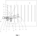
- FIG. 1 and FIG. 2 show a control system 1 for controlling a wired vehicle fleet 2 comprising a supply unit 3a, a first vehicle 4 connected with the supply unit 3a by a first bendable connection element 6 and a second vehicle 5 also connected with the supply unit 3a by a second bendable connection element 7.
- the first vehicle 4 and the second vehicle 5 of the vehicle fleet 2 are operating in an agricultural field 8.
- the first vehicle 4 moves along a wayline 16 and the second vehicle 5 moves along a wayline 17.
- the first vehicle 4 and the second vehicle 5 may turn in a headland 13 of the agricultural field 8 so that the first vehicle 4 will continue to move along a first wayline 9 and the second vehicle 5 will continue to move along a second wayline 10.
- the supply unit 3a is a stationary entity such as a container.
- the supply unit 3a is placed at a corner of the agricultural field 8 so that the first and the second vehicle 4 and 5 can easily pass the stationary supply unit 3a when moving along their waylines in the agricultural field 8.
- the lengths 28 and 29 of the first and the second bendable connection element 6 and 7 may be adjustable to prevent a break of the bendable connection elements 6 and 7 when the first and second vehicle 4 and 5 are getting away from the supply unit 3a.
- the supply unit 3a may comprise a winch 22 for the bendable connection element 6 and a winch 23 for the bendable connection element 7 to adjust separately the lengths 28 and 29 by unwinding or winding up of the bendable connection elements 6 and 7.
- one end of the first bendable connection element 6 is connected to the winch 22 and the other end of the first bendable connection element 6 is connected to a distal end 24 of a height variable mast 18 of the first vehicle 4 (see also FIG. 5 ).
- one end of the second bendable connection element 7 is connected to the winch 23 and the other end of the first second bendable connection element 7 is connected to a distal end 24 of a height variable mast 18 of the second vehicle 5 (see also FIG. 5 ).
- the heights of the winch 22 and winch 23 are adjustable, too.
- the height of the first and the second bendable connection element 6 and 7 are adjustable by adjusting the height of the corresponding mast 18 or the winch 22, 23.
- the first bendable connection element 6 as well as the second bendable connection element 7 may comprise each a slack 19.
- the slack 19 may depend on the corresponding lengths 28 and 29 between the one end and the other end of the first and second bendable connection element 6 and 7.
- the first bendable connection element 6 may be covered by a first safety zone 20 and the second bendable connection element 7 may be covered by a second safety zone 21 as explained later on.
- Crop 32 growing on the agricultural field 8 may be treated by the first vehicle 4 and the second vehicle 5 such as spraying, weeding or mowing between the rows of crop 32.
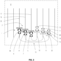
- FIG. 3 and FIG. 4 show also a control system 1 for controlling a wired vehicle fleet 2 comprising a supply unit 3b, a first vehicle 4 connected with the supply unit 3b by a first bendable connection element 6 and a second vehicle 5 also connected with the supply unit 3b by a second bendable connection element 7.
- the control system 1 of FIG. 3 and FIG. 4 may be the same as of FIG. 1 and FIG. 2 except for the stationary supply unit 3a.
- the supply unit 3b shown in FIG. 3 and FIG. 4 is a movable entity such as a vehicle.
- the supply unit 3b may be a vehicle of the same type as the first or the second vehicle 4 or 5.
- the vehicle fleet 2 shown in FIG. 3 and FIG. 4 comprises three agricultural vehicles which may operate in a cooperative manner in the agricultural field 8.
- the supply unit 3a illustrated in FIG. 1 and FIG. 2 as well as the supply unit 3b illustrated in FIG. 3 and FIG. 4 may comprise the same components as for example an energy storage and a tank for resources needed for the field operation.
- the energy storage may be a battery for storing electrical energy.
- the tank may comprise several tanks for example to store fuel for propelling the vehicles of the vehicle fleet 2 or agents such as fertilizers or pesticides to be dispensed on crops of the agricultural field 8 by the vehicles of the vehicle fleet 2.
- the electrical energy and the resources may be transferred from the supply unit 3a or 3b to the first and second vehicle 4 and 5 through the corresponding first and second bendable connection elements 6 and 7 the first and second vehicle 4 and 5 are connected with.
- the first and the second bendable connection element 6 and 7 may comprise a wire, a pipe or both for transferring the electrical energy or the resources.
- the wire may also be used to transfer data or signals between the supply unit 3a, 3b and the vehicles 4, 5.
- the first vehicle 4 moves along a wayline 16 and the second vehicle 5 moves along a wayline 18 analogously to FIG. 1 .
- the supply unit 3b moves along a wayline 35.
- the first vehicle 4, the second vehicle 5 and the supply unit 3b may turn in a headland 13 of the agricultural field 8 so that the first vehicle 4 will continue to move along a first wayline 9, the second vehicle 5 will continue to move along a second wayline 10 and the supply unit 3b will continue to move along a third wayline 33.
- the heights of the first and second bendable connection element 6 and 7 are adjustable in an analogous manner as described above. But in contrast to FIG. 2 , the first and the second bendable connection element 6 and 7 are fixed each to a carrier rope 36 by several fixations 37 to reduce the slack 19. (The control system 1 according to FIG. 1 and FIG. 2 may also be equipped with carrier ropes 36).
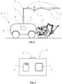
- FIG. 5 shows an agricultural vehicle 38 connected with an implement 39 such as a mower to harvest or cut crop 32.
- the agricultural vehicle 38 may be of any type such as an agricultural robot, a tractor, a harvester, etc.
- the agricultural vehicle 38 may represent at least one of the first vehicle 4, the second vehicle 5 and the supply unit 3b.
- the agricultural vehicle 38 comprises a roof 41 on which a height variable mast 18 is mounted.
- a distal end 24 of the mast 18 is connected with the first bendable connection element 6 or the second bendable connection element 7.
- the height variable mast 18 may comprise a telescopic extendable element to raise or lower the distal end 24 of the mast 18 to adjust the height of the first or the second bendable connection element 6 or 7.
- a carrier rope 36 may be optionally connected to the mast 18.
- the first or the second bendable connection element 6 or 7 may be connected to the carrier rope 36 by one or more fixations 37 for reducing a slack 19 of the bendable connection element.
- the more fixations 37 are used to connect the bendable connection element 6, 7 to the carrier rope 36 the more the slack 19 may be reduced.
- At least one of the supply units 3a, 3b, the first and the second vehicle 4 and 5 comprises a control unit 40.
- the control unit 40 may be integrated in the supply unit 3a shown in FIG. 1 .
- the control unit 40 may be integrated in the agricultural vehicle 38 representing the supply unit 3b as shown in FIG. 3 , FIG. 4 and FIG. 5 .
- control unit 40 may be integrated in any of the first and second vehicle 4 and 5. More alternatively, the control unit 40 may be provided beyond supply unit 3a, 3b, the first and the second vehicle 4 and 5 and communicate with supply unit 3a, 3b, the first and the second vehicle 4 and 5 via cellular network or any other wireless communication.
- FIG. 6 shows the control unit 40 comprising an interface 42, a controller 43 and a memory 44.
- the control unit 40 may receive and send signals or data via the interface 42.
- the interface 42 may be a wireless interface or a connector.
- the interface 42 may additionally be provided to communicate wirelessly to further stationary or mobile devices to enable monitoring or planning of the wired vehicle fleet 2 by a human operator.
- the controller 43 may store the data or signals received by the control unit 40 in the memory 44.
- the memory 44 may contain additional data or executable programs, for example in terms of a computer-implemented method, that may be retrieved, processed or carried out by the controller 43. Data or signals resulting from the processing of data or signals or from the execution of a program may be stored to the memory 44 or sent to the interface 42 by the controller 43.
- the first bendable connection element 6 and the second bendable connection element 7 may be connected to the interface 42 of the control unit 40.
- the control unit 40 may communicate with the first vehicle 4 and the second vehicle 5 through the corresponding bendable connection elements 6 and 7.
- the control unit 40 may control the vehicle speed or the steering of the first and the second vehicle 4 and 5 to move the first and the second vehicle 4 and 5 along their waylines.
- the control unit 40 may also control the implement 39 of the first and the second vehicle 4 and 5.
- the control unit 40 may also control the vehicle speed or the steering of the supply units 3b as well as any implement 39 connected to the supply unit 3b.
- FIG. 7 shows the same control system 1 as shown in FIG. 4 wherein the first bendable connection element 6 and the second bendable connection element 7 are additionally equipped with at least one floating unit 45 for carrying the bendable connection elements in the air.
- the floating units 45 may be fixed to the fixations 37 and may comprise an envelope to enclose a gas volume.
- the gas volume may comprise a gas lighter than air as for example helium to provide a buoyancy force.
- the floating unit 45 may be of the same type and may have the same functionality as the floating unit described in the GB patent application, application number 2205518.0 , mentioned above.
- FIG. 8 shows a control system 1 similar to FIG. 7 wherein drones (unmanned aerial vehicles) are operating as first and second vehicle 4 and 5. I. e. in contrast to ground-based agricultural vehicles, the drones may fly over the agricultural field 8 to treat the crop 32 and may vary their altitudes. The height of the winch 22 and winch 23 may be adjusted to the corresponding altitude of the first and second vehicle 4 and 5.
- drones unmanned aerial vehicles
- the drones may fly over the agricultural field 8 to treat the crop 32 and may vary their altitudes.
- the height of the winch 22 and winch 23 may be adjusted to the corresponding altitude of the first and second vehicle 4 and 5.
- FIG. 9 shows a flow diagram of a first method M1.
- the method M1 may be a computer implemented method and may be carried out by the control unit 40.
- the method M1 may be part of a wayline planning for vehicle fleet 2 prior to moving on agricultural field 8.
- the method M1 may be started before one of the moveable supply unit 3b, the first and the second vehicle 4 and 5 approaches the headland 13 of the agricultural field 8.
- the method M1 works with each control system 1 as shown in FIG. 2 , FIG. 4 , FIG. 7 and FIG. 8 .
- the method M1 starts with step S100 and proceeds to step S101 for determining a minimum and a maximum height of the first bendable connection element 6.
- the control unit 40 may determine the height 30 of the distal end 24 of the mast 18 of the first vehicle 4 to determine the maximum height of the first bendable connection element 6.
- the minimum height may be determined by the slack 19 of the first bendable connection element 6 by the control unit 40.
- the slack 19 may be calculated by the control unit 40 based on a length of the bendable connection element.
- the minimum height of the first bendable connection element 6 may be a predefined parameter stored in the memory 44 and retrieved by the control unit 40.
- the method proceeds to step S102 for determining a minimum and a maximum height of the second bendable connection element 7.
- the control unit 40 may determine the minimum and the maximum height of the second bendable connection element 7 based on the height 31 of the distal end 24 of the mast 18 of the second vehicle 5 and the slack 19 of the second bendable connection element 7 analogously to the determination of the first bendable connection element 6 as described above.
- the control unit 40 determines a first wayline 9 of the first vehicle 4.
- the first wayline 9 may be a straight line through the agricultural field 8 and may be parallel to at least one other wayline.
- the first wayline 9 may be stored in the memory 44 or may be transferred to the first vehicle 4 for guiding the first vehicle 4 along the first wayline 9.
- the control unit 40 may determine control signals for guiding the first vehicle 4 along the first wayline 9 and may send the control signals to the first vehicle 4.
- the first vehicle 4 may travel autonomously along the first wayline 9 for an automated field operation.
- step S104 the method may proceed to step S104. Otherwise, the method proceeds to step S105 and S106 or S107 to determine a second wayline of the second vehicle 5.
- the control unit 40 may determine a third wayline 33 for the moveable supply unit 3b.
- the third wayline 33 may be a straight line through the agricultural field 8 and may be parallel to at least one other wayline, e. g. the first wayline 9.
- the third wayline 33 may be stored in the memory 44.
- the control unit 40 may determine control signals for guiding the supply unit 3b along the third wayline 33 and may control the moveable supply unit 3b accordingly.
- the supply unit 3b may travel autonomously along the third wayline 33 for an automated field operation.
- step S105 the control unit 40 determines whether the minimum height of the first bendable connection element 6 is higher than the maximum height of the second bendable connection element 7 (first option) or whether the minimum height of the second bendable connection element 7 is higher than the maximum height of the first bendable connection element 6 (second option). Then, the control unit 40 determines a second wayline 10 of the second vehicle 5 depending on the heights of the first and second bendable connection element 6 and 7 so that the first and the second bendable connection elements 6 and 7 won't collide against each other when the first vehicle 4 and the second vehicle 5 travel along their corresponding first and second waylines 9 and 10.
- the method proceeds to step S106 and a wayline extending between the first wayline 9 and the position of the supply unit 3a, 3b will be determined as the second wayline 10 by the control unit 40 as shown in FIG. 1 or FIG. 3 .
- the method proceeds to step S107 and a wayline extending next to the first wayline 9 but having a greater distance from the supply unit 3a, 3b than the first wayline 9 will be determined as the second wayline 10 by the control unit 40.
- the vehicle connected with the bendable connection element having the lower height is guided closer to the supply unit 3a, 3b than the other vehicle connected with the bendable connection element having the greater height.
- the position of the moveable supply unit 3b may be the current position of the supply unit 3b.
- the position of the moveable supply unit 3b may be defined by the third wayline 33 determined at step S104 and may be an anticipated position 34 of the supply unit 3b.
- the second wayline 10 may be a straight line through the agricultural field 8 and may be parallel to at least one other wayline, e. g. the first wayline 9.
- the second wayline 10 may be stored in the memory 44 or may be transferred to the second vehicle 5 for guiding the second vehicle 5 along the second wayline 10.
- the control unit 40 may determine control signals for guiding the second vehicle 5 along the second wayline 10 and may send the control signals to the second vehicle 5.
- the second vehicle 5 may travel autonomously along the second wayline 10 for an automated field operation.
- step S106 or S107 the method proceeds to step S108 and the first method M1 ends.
- the control unit 40 determined a first and a second wayline 9 and 10 for the first and second vehicle 4 and 5 which enable a travel of the first and the second vehicle 4 and 5 through the agricultural field 8 without a collision between the first bendable connection element 6 and the second bendable connection element 7.
- the first method M1 may be carried out by control unit 40 which may be beyond supply unit 3a, 3b, the first and the second vehicle 4 and 5 to enable off-board wayline planning.
- the wayline plan may then be communicated to vehicle fleet 2.
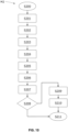
- FIG. 10 shows a flow diagram of a second method M2.
- the method M2 may be a computer implemented method and may be carried out by the control unit 40.
- the method M2 works with each control system 1 as shown in FIG. 2 , FIG. 4 , FIG. 7 and FIG. 8 .
- the method M2 starts with step S200 and proceeds to step S201 for determining a first wayline 9 of the first vehicle 4.
- the first wayline 9 may be determined by the control unit 40 analogously to step S103 of method M1.
- the method M2 may be part of a collision avoidance system.
- the first and second waylines 9, 10 may be part of a predetermined wayline planning.
- the waylines may change during operation, e. g. if the vehicles 4 and 5 are provided with means for obstacle detection and a detected obstacle such as a stone or a tree forces the vehicles 4 or 5 to leave the predetermined wayline.
- step S202 the control unit 40 determines a second wayline 10 of the second vehicle 5.
- the second wayline 10 be determined by the control unit 40 analogously to step S106 or S107 of method M1.
- the method proceeds to step S203 and the control unit 40 determines a first safety zone 20 in consideration of a length 28 of the first bendable connection element 6 and a minimum and a maximum height of the first bendable connection element 6 as can be seen in FIG. 2 and FIG. 4 .
- the length 28 of the first bendable connection element 6 depends on the distance between the first vehicle 4 and the supply unit 3a, 3b as it is apparent from FIG. 1 to FIG. 4 . Since the distance between the first vehicle 4 and the supply unit 3a, 3b may vary the length 28 of the first bendable connection element 6 may vary accordingly.
- the minimum height of the first bendable connection element 6 depends on the slack 19 of the first bendable connection element 6 as can be seen in FIG. 2 and FIG. 4 .
- the slack 19 may be reduced if the first bendable connection element 6 is attached to the carrier rope 36 by at least a fixation 37 as can be seen in FIG. 4 and FIG. 5 .
- the maximum height of the first bendable connection element 6 may depend on the height 30 of the distal end 24 of the mast 18 of the first vehicle 4 as can be seen in FIG. 2 and FIG. 4 . Since the height of the height variable mast 18 is adjustable the maximum height of the first bendable connection element 6 may vary accordingly.
- the maximum height of the first bendable connection element 6 may depend on the height of the winch 22 of the first bendable connection element 6. Alternatively, the maximum height of the first bendable connection element 6 may depend on a floating height of at least one floating unit 45 attached to the first bendable connection element 6 as can be seen in FIG.
- the first safety zone 20 determined by the control unit 40 covers the first bendable connection element 6 completely and reaches from the winch 22 of the first bendable connection element 6 to the mast 18 of the first vehicle 4 and from the maximum height to the minimum height of the first bendable connection element 6.
- the first safety zone 20 may be shaped as a cuboid.
- the first safety zone 20 may be determined as a tube or any other solid surrounding the first bendable connection element 6.
- the method proceeds to step S204 and the control unit 40 determines a second safety zone 21 in consideration of a length 29 of the second bendable connection element 7 and a minimum and a maximum height of the second bendable connection element 7 as can be seen in FIG. 2 and FIG. 4 .
- the second safety zone 21 may be determined analogously to the first safety zone 20.
- the length 29 of the second bendable connection element 7 depends on the distance between the second vehicle 5 and the supply unit 3a, 3b as it is apparent from FIG. 1 to FIG. 4 . Since the distance between the second vehicle 5 and the supply unit 3a, 3b may vary the length 29 of the second bendable connection element 7 may vary accordingly.
- the minimum height of the second bendable connection element 7 depends on the slack 19 of the second bendable connection element 7 as can be seen in FIG. 2 and FIG. 4 .
- the slack 19 may be reduced if the second bendable connection element 7 is attached to the carrier rope 36 by at least a fixation 37 as can be seen in FIG. 4 and FIG. 5 .
- the maximum height of the second bendable connection element 7 may depend on the height 31 of the distal end 24 of the mast 18 of the second vehicle 5 as can be seen in FIG. 2 and FIG. 4 . Since the height 31 of the height variable mast 18 is adjustable the maximum height of the second bendable connection element 7 may vary accordingly.
- the maximum height of the second bendable connection element 7 may depend on the height of the winch 23 of the second bendable connection element 7.
- the maximum height of the second bendable connection element 7 may depend on a floating height of at least one floating unit 45 attached to the second bendable connection element 7 as can be seen in FIG. 7 and FIG. 8 .
- the second safety zone 21 determined by the control unit 40 covers the second bendable connection element 7 completely and reaches from the winch 23 of the second bendable connection element 7 to the mast 18 of the second vehicle 5 and from the maximum height to the minimum height of the second bendable connection element 7.
- the second safety zone 21 may be shaped as a cuboid.
- the second safety zone 21 may be determined as a tube or any other solid surrounding the second bendable connection element 7.
- the bendable connection elements 6 and 7 will change their positions.
- the first bendable connection element will change its position as indicated by numeral 14 when the first vehicle 4 arrives a vehicle position 11 and the second bendable connection element 7 will change its position as indicated by numeral 15 when the second vehicle 5 arrives a vehicle position 12 (see FIG. 1 and FIG. 3 ).
- the position of the first and second bendable connection elements 6 and 7 depend on the position of the supply unit 3a, 3b regardless whether the supply unit 3a, 3b changes its position, e. g. to a position indicated by numeral 34 (see FIG. 3 ) or not.
- first and second bendable connection elements 6 and 7 may affect the lengths 28 and 29 and the maximum and the minimum heights of the first and second bendable connection elements 6 and 7 resulting in different variations of the first safety zone 20 of the first bendable connection element 6 and in different variations of the second safety zone 21 of the second bendable connection element 7.
- first safety zone 20 will be extended to the safety zone 20* to cover the first bendable connection element 6 extended to the bendable connection element 14. I. e., a variation of the first safety zone 20 is defined by the extended safety zone 20*.
- control unit 40 updates the first and second safety zones 20 and 21 in dependence of the different positions of the supply unit 3b and the first and second vehicle 4 and 5 and determines the corresponding variations of the first and second safety zone 20 and 21 for the different positions.
- the method proceeds to step S205 and the control unit 40 anticipates variations of the first safety zone 20 based on anticipated positions 11 of the first vehicle 4 moving along the first wayline 9 (see FIG. 1 to FIG. 4 .
- the anticipated positions 11 of the first vehicle 4 may be determined by the control unit 40 based on the current position of the first vehicle 4, the first wayline 9, the driving speed of the first vehicle 4 and the operation time of the vehicle fleet 2.
- the anticipated variations of the first safety zone 20 may be determined by the control unit 40 based on the changes of the length 28 and the maximum and the minimum height of the first bendable connection element 6 affected by the anticipated positions 11 of the first vehicle 4.
- step S206 the control unit 40 anticipates variations of the second safety zone 21 based on anticipated positions 12 of the second vehicle 5 moving along the second wayline 10 analogously to step S205 (see FIG. 1 to FIG. 4 ).
- the anticipated positions 12 of the second vehicle 5 may be determined by the control unit 40 based on the current position of the second vehicle 5, the second wayline 10, the driving speed of the second vehicle 5 and the operation time of the vehicle fleet 2.
- the anticipated variations of the second safety zone 21 may be determined by the control unit 40 based on the changes of the length 29 and the maximum and the minimum height of the second bendable connection element 7 affected by the anticipated positions 12 of the second vehicle 5.
- the method proceeds optionally to step S207 and the control unit 40 optionally determines a third wayline 33 of the supply unit 3b and anticipates variations of the first safety zone 20 and the second safety zone 21 based on anticipated positions 34 of the supply unit 3b moving along the third wayline 33.
- the anticipated positions 34 of the supply unit 3b may be determined by the control unit 40 based on the current position of the supply unit 3b, the third wayline 33, the driving speed of the supply unit 3b and the operation time of the vehicle fleet 2.
- step S208 the control unit 40 anticipates a collision of the first bendable connection element 6 with the second bendable connection element 7 if an anticipated variation of the first safety zone 20 intersects an anticipated variation of the second safety zone 21.
- the first safety zone 20 intersects the second safety zone 21 within a collision zone 27 indicating a collision at the same operation time of the vehicle fleet 2.
- a preventive measure may be a determination of an alternative wayline of the movable supply unit 3b.
- Another preventive measure may be a determination of an alternative wayline of the second vehicle 5.
- Another preventive measure may be to carry out at least one of the steps S100 to S108 of the first method M1.
- the method may optionally proceed to step S210 and the control unit 40 may optionally adjust the height of the first or the second bendable connection element 6 or 7.
- Step S210 may also be executed as a preventive measure to avoid an anticipated collision.
- the height of the first or second bendable connection element 6 or 7 can be adjusted by an adjustment of the heights 30 or 31 of the variable mast 18 or by an adjustment of the height of the winch 22 or winch 23. So, the control unit 40 may adjust the height of the first and second bendable connection element 6 or 7 such that the maximum height of the bendable connection element connected with the vehicle being guided closer to the supply unit 3a, 3b is lower than the minimum height of the bendable connection element connected with the other vehicle being guided with a greater distance from the supply unit 3a, 3b.
- the control unit 40 may optionally consider the size of the first vehicle 4 with respect to the first safety zone 20 and the size of the second vehicle 5 with respect to the second safety zone 21.
- the first vehicle 4 may be covered by the first safety zone 20 extended with safety zone 25 and the second vehicle 5 may be covered by the second safety zone 21 extended with safety zone 26.
- the extended safety zones 25 and 26 may encompass the first and the second vehicle 4 and 5 irrespective of the type of the first and the second vehicle 4 and 5 so that ground-based agricultural vehicles (see FIG. 2 , FIG. 4 , FIG. 7 ) may be encompassed as well as drones (see FIG. 8 ).
- the first and the second safety zones 20 and 21 is not restricted to the first and second bendable connection elements 6 and 7 only.
- step S208 If a collision didn't be anticipated by the control unit 40 at step S208, the method proceeds to step S211. Finally, the second method M2 ends with step S211.
- Both methods M1 and M2 enable the control system 1 to provide a (predictive) wayline plan for collision free travel of the wired vehicle fleet 2 in agricultural field 8 and also enable to avoid collision during the operation of the wired vehicle fleet 2 (with or without a predetermined wayline plan).
Landscapes
- Engineering & Computer Science (AREA)
- Remote Sensing (AREA)
- Radar, Positioning & Navigation (AREA)
- Aviation & Aerospace Engineering (AREA)
- Mechanical Engineering (AREA)
- Power Engineering (AREA)
- Physics & Mathematics (AREA)
- General Physics & Mathematics (AREA)
- Automation & Control Theory (AREA)
- Transportation (AREA)
- Life Sciences & Earth Sciences (AREA)
- Sustainable Energy (AREA)
- Sustainable Development (AREA)
- Vehicle Body Suspensions (AREA)
- Control Of Position, Course, Altitude, Or Attitude Of Moving Bodies (AREA)
Abstract
Description
- The present disclosure relates generally to a method and a control system for controlling a wired vehicle fleet. The vehicle fleet may comprise several vehicles each connected to a supply unit for supplying the vehicles with energy or any other resources.
-
U. S. patent application 2020/0298641 A1, "Current supply system for a team of vehicles," published on September 24, 2020 , discloses a vehicle fleet of three vehicles connected by a connection element such as a wire. One of the three vehicles operates as a leading vehicle. The other two vehicles follow the leading vehicle. To avoid a collision with one of the connection elements a proper operation of the vehicle fleet needs to be ensured. - It is an objective to coordinate the operation of the vehicles of a vehicle fleet so that a collision of a connection element with another connection element or with one of the vehicles is avoided.
- According to an aspect of the invention there is provided a control system for controlling a wired vehicle fleet. The control system includes a supply unit, a first vehicle connected with the supply unit by a first bendable connection element, a second vehicle connected with the supply unit by a second bendable connection element and a control unit. The control unit is configured to carry out any steps of the methods described below.
- The first and the second vehicle may be an agricultural vehicle such as a tractor, a sprayer, a combine, a harvester or a drone. The first and the second vehicle may comprise an implement such as a mover, a plough or a trailer. The supply unit may be a stationary entity or a vehicle such as for example the first or the second vehicle. The supply unit may be equipped with an energy storage or a tank to store (electrical) energy or any other resources. The first and the second vehicle may be supplied by the supply unit with energy, e. g. electrical energy or fuel, or any other resource, e. g. fertilizer or pesticides, through the bendable connection elements.
- The control system may also include a floating unit for carrying the first or the second bendable connection element in the air.
- The floating unit may be a flying object such as a drone or a balloon. The floating unit may be attached to one of the bendable connection elements and may lift the bendable connection element to reduce the slack or to reduce a pulling force in the bendable connection element, as for example a floating unit as disclosed in the
GB patent application, application number 2205518.0, "Supply system for a vehicle connected to a platform", filed on April 13, 2022 - The first or the second bendable connection element may be a pipe for supplying a fluid.
- Alternatively, the first or the second bendable connection element may be a wire for transferring electrical energy or a combination of a wire and a pipe. The fluid may be water, a pesticide or a fertilizer. While the fluid is transferred from the supply unit to the first or the second vehicle the fluid may be dispensed by the first or the second vehicle for treating crops of an agricultural field.
- At least one of the first vehicle, the second vehicle and the supply unit may include a height variable mast for connecting the first or the second bendable connection element.
- The height variable mast may comprise a telescopic extendable element controllable by the control unit. The height variable mast may be mounted on a roof of the supply unit, the first vehicle or the second vehicle.
- The first vehicle may include a first height variable mast connected with the first bendable connection element for adjusting the maximum height of the first bendable connection element, the second vehicle may include a second height variable mast connected with the second bendable connection element for adjusting the maximum height of the second bendable connection element. The control unit may be configured to adjust a maximum height of each of the first and second bendable connection elements so that the maximum height of the bendable connection element of the one of the first and second vehicle being closer to the supply unit is below the minimum height of the bendable connection element of the other vehicle being more distant from the supply unit.
- I. e., the bendable connection elements are arranged in a cascading arrangement to avoid a collision between two bendable connection elements. The height of a bendable connection element connected to the vehicle being more distant from the supply unit is higher than the height of a bendable connection element connected to the vehicle being closer to the supply unit so that the bendable connection element of the vehicle being more distant from the supply unit may span over the bendable connection element of the vehicle being closer to the supply unit. Thus, a collision between the first and the second bendable connection element may be avoided.
- A further aspect provides a first method for controlling a wired vehicle fleet including a first vehicle connected with a supply unit by a first bendable connection element and a second vehicle connected with the supply unit by a second bendable connection element. The method includes the steps of determining a minimum and a maximum height of the first bendable connection element, determining a minimum and a maximum height of the second bendable connection element, determining a first wayline of the first vehicle and determining a second wayline of the second vehicle depending on the heights of the first and second bendable connection element.
- The maximum height of the first bendable connection element may be defined by the connection points of the first bendable connection element with the first vehicle and the supply unit. The maximum height of the second bendable connection element may be defined by the connection points of the second bendable connection element with the second vehicle and the supply unit. Both heights may be predefined values stored in the control unit as parameters. The minimum height of the first bendable connection element may depend on a slack of the first bendable connection element connected between the first vehicle and the supply unit. The minimum height of the second bendable connection element may depend on a slack of the second bendable connection element connected between the second vehicle and the supply unit. The slack of each bendable connection element may depend on the length of the corresponding bendable connection element and may be calculated by the control unit.
- The waylines of the first and second vehicle may be determined by the control unit based on a path planning algorithm stored in a memory of the control unit. Since the wayline of the second vehicle depends on the height of the first and the second bendable connection element the control unit may determine a second wayline for which a collision between the first and the second bendable connection element may be avoided when the first and the second vehicle move along their corresponding first and second waylines.
- The second wayline may run between the first wayline and a location of the supply unit if the minimum height of the first bendable connection element is higher than the maximum height of the second bendable connection element. The first wayline may run between the second wayline and the location of the supply unit if the maximum height of the first bendable connection element is lower than the minimum height of the second bendable connection element.
- Both, in the one and in the other case, the control unit determines the second wayline of the second vehicle depending on the height of the first and second bendable connection element. Additionally, the control unit determines a second wayline for which a collision between the first and the second bendable connection element may be avoided when the first and the second vehicle move along their corresponding first and second waylines. Hence, the first and the second bendable connection elements may be arranged in a cascading arrangement as described above.
- The method may also include the step of determining a third wayline of the supply unit. Then, the location of the supply unit may be defined by the third wayline.
- The control unit may determine the third wayline if the supply unit is a vehicle. The supply unit may move along the third wayline. The first, the second and the third wayline may be aligned parallel to each other so that the first, the second and the third vehicle may move parallel to each other, too. Additionally, the second wayline may run between the first wayline and the third wayline if the minimum height of the first bendable connection element is higher than the maximum height of the second bendable connection element. The first wayline may run between the second wayline and the third wayline if the maximum height of the first bendable connection element is lower than the minimum height of the second bendable connection element.
- Another aspect includes a second method for controlling a wired vehicle fleet including a first vehicle connected with a supply unit by a first bendable connection element and a second vehicle connected with the supply unit by a second bendable connection element. The method includes the steps of determining a first wayline of the first vehicle, determining a second wayline of the second vehicle, determining a first safety zone in consideration of a length of the first bendable connection element and a minimum and a maximum height of the first bendable connection element, determining a second safety zone in consideration of a length of the second bendable connection element and a minimum and a maximum height of the second bendable connection element, anticipating variations of the first safety zone based on anticipated positions of the first vehicle moving along the first wayline, anticipating variations of the second safety zone based on anticipated positions of the second vehicle moving along the second wayline, anticipating a collision of the first bendable connection element with the second bendable connection element if an anticipated variation of the first safety zone intersects an anticipated variation of the second safety zone.
- The first safety zone may be a virtual zone and may cover the first bendable connection element. Analogously, the second safety zone may be a virtual zone and may cover the second bendable connection element. The first and the second safety zone may be determined by the control unit and may be of any shape, for example a three dimensional object as a cuboid enclosing the corresponding bendable connection element or a bent tube surrounding the corresponding bendable connection element.
- The control unit may anticipate the positions of the first and the second vehicle moving along their waylines based on their speed. Since the first bendable connection element is connected with the first vehicle and the second bendable connection element is connected with the second vehicle the first and the second bendable connection elements will follow the movement of the first and the second vehicle accordingly. Then, the control unit may anticipate the variations of the first and second safety zone based on the anticipated positions of the first and the second vehicle and the (anticipated) position of the supply unit. Based on the anticipated variations of the first and second safety zone the control unit may determine a possible collision between the first bendable connection element and the second bendable connection element before a real collision occurs.
- The second method may include the steps of determining a third wayline of the supply unit and anticipating variations of the first safety zone and the second safety zone based on anticipated positions of the supply unit moving along the third wayline.
- Thus, the control unit may anticipate the positions of the supply unit, the first and the second vehicle moving along their waylines based on their speed. Since the first bendable connection element and the second bendable connection element are connected with the supply unit the first and the second bendable connection elements will follow the movement of the supply unit accordingly. Then, the control unit may also consider the movement of the supply unit for anticipating the variations of the first and second safety zone.
- The second method may also include the step of determining an alternative wayline of the supply unit if a collision of the first bendable connection element with the second bendable connection element is anticipated.
- The second method may also include the step of determining an alternative wayline of the second vehicle if a collision of the first bendable connection element with the second bendable connection element is anticipated.
- When the control unit determines an alternative wayline of the supply unit or an alternative wayline of the second vehicle the control unit may consider the height of the first and second bendable connection element to determine a wayline for which a collision between the first and the second bendable connection element may be avoided when the supply unit, the first and the second vehicle move along their corresponding waylines.
- The second method may also include the step of carrying out at least one step of the first method if a collision of the first bendable connection element with the second bendable connection element is anticipated.
- Thus, the control unit may determine a first wayline of the first vehicle and a second wayline of the second vehicle depending on the height of the first and second bendable connection element. The control unit may determine a new first wayline of the first vehicle or a new second wayline of the second vehicle if a first wayline or a second wayline was determined before.
- The method may also include the step of adjusting the height of the first or the second bendable connection element.
- The control unit may arrange the minimum height of the bendable connection element of the first vehicle above the maximum height of the bendable connection element of the second vehicle if the second wayline runs between the first wayline and a location of the supply unit by lowering or raising at least one of the height variable masts of the first and second vehicle. The control unit may arrange the minimum height of the bendable connection element of the second vehicle above the maximum height of the bendable connection element of the first vehicle if the first wayline runs between the second wayline and a location of the supply unit by lowering or raising at least one of the height variable masts of the first and second vehicle. According to this adjustment of the first or second bendable connection element a collision between the first and the second bendable connection element may be avoided.
- The method may also consider a size of the first vehicle for the determination of the first safety zone and may also consider a size of the second vehicle for the determination of the second safety zone.
- I. e., the first safety zone may enclose the first bendable connection element and the first vehicle; the second safety zone may enclose the second bendable connection element and the second vehicle. Thus, a collision between the first vehicle and the second bendable connection element or a collision between the second vehicle and the first bendable connection element may be anticipated by the control unit if an anticipated variation of the first safety zone intersects an anticipated variation of the second safety zone.
- The method may also consider a third safety zone for the supply unit. The third safety zone may be part of the first or second safety zone.
- The control unit of the control system may be configured to determine the maximum height of the first or the second bendable connection element in consideration of a floating height of the floating unit or a size of the floating unit.
- Hence, the control unit may determine the first safety zone or the second safety zone in consideration of a position or a size of the floating unit. The floating unit may be enclosed by the first or second safety zone so that a collision of the floating unit with a bendable connection element may be anticipated by the control unit.
- The floating unit may include an envelope for enclosing a gas volume.
- The envelope avoids a dissipation of the gas. The gas may be a fluid lighter than air such as helium for causing a lifting effect to carry the bendable connection element in the air.
- Within the scope of this application it should be understood that the various aspects, embodiments, examples and alternatives set out herein, and individual features thereof may be taken independently or in any possible and compatible combination. Where features are described with reference to a single aspect or embodiment, it should be understood that such features are applicable to all aspects and embodiments unless otherwise stated or where such features are incompatible.
- Several aspects of the invention will now be described, by way of example only, with reference to the accompanying drawings, in which:
-
FIG. 1 illustrates a control system for controlling a wired vehicle fleet. -
FIG. 2 illustrates a control system for controlling a wired vehicle fleet with safety zones covering bendable connection elements. -
FIG. 3 illustrates a control system for controlling a wired vehicle fleet with a moveable supply unit. -
FIG. 4 illustrates a control system for controlling a wired vehicle fleet with safety zones covering bendable connection elements fixed to carrier ropes. -
FIG. 5 is a simplified view of an agricultural vehicle as part of the vehicle fleet. -
FIG. 6 illustrates simplified view of a control unit. -
FIG. 7 illustrates a control system for controlling a wired vehicle fleet with safety zones covering bendable connection elements and floating units. -
FIG. 8 illustrates a control system for controlling a wired vehicle fleet with safety zones covering UAVs, bendable connection elements and floating units. -
FIG. 9 illustrates a flow diagram for a first method. -
FIG. 10 illustrates a flow diagram for a second method. -
FIG. 1 andFIG. 2 show acontrol system 1 for controlling awired vehicle fleet 2 comprising a supply unit 3a, afirst vehicle 4 connected with the supply unit 3a by a firstbendable connection element 6 and asecond vehicle 5 also connected with the supply unit 3a by a secondbendable connection element 7. Thefirst vehicle 4 and thesecond vehicle 5 of thevehicle fleet 2 are operating in anagricultural field 8. Thefirst vehicle 4 moves along awayline 16 and thesecond vehicle 5 moves along awayline 17. At the end of thewaylines first vehicle 4 and thesecond vehicle 5 may turn in aheadland 13 of theagricultural field 8 so that thefirst vehicle 4 will continue to move along afirst wayline 9 and thesecond vehicle 5 will continue to move along asecond wayline 10. - The supply unit 3a is a stationary entity such as a container. The supply unit 3a is placed at a corner of the
agricultural field 8 so that the first and thesecond vehicle agricultural field 8. - While the first and
second vehicles agricultural field 8 the first andsecond vehicles bendable connection elements lengths bendable connection element bendable connection elements second vehicle winch 22 for thebendable connection element 6 and awinch 23 for thebendable connection element 7 to adjust separately thelengths bendable connection elements - As can be seen in
FIG. 2 , one end of the firstbendable connection element 6 is connected to thewinch 22 and the other end of the firstbendable connection element 6 is connected to adistal end 24 of aheight variable mast 18 of the first vehicle 4 (see alsoFIG. 5 ). Analogously, one end of the secondbendable connection element 7 is connected to thewinch 23 and the other end of the first secondbendable connection element 7 is connected to adistal end 24 of aheight variable mast 18 of the second vehicle 5 (see alsoFIG. 5 ). The heights of thewinch 22 andwinch 23 are adjustable, too. Hence, the height of the first and the secondbendable connection element corresponding mast 18 or thewinch - The first
bendable connection element 6 as well as the secondbendable connection element 7 may comprise each aslack 19. The slack 19 may depend on the correspondinglengths bendable connection element - The first
bendable connection element 6 may be covered by afirst safety zone 20 and the secondbendable connection element 7 may be covered by asecond safety zone 21 as explained later on. -
Crop 32 growing on theagricultural field 8 may be treated by thefirst vehicle 4 and thesecond vehicle 5 such as spraying, weeding or mowing between the rows ofcrop 32. -
FIG. 3 andFIG. 4 show also acontrol system 1 for controlling awired vehicle fleet 2 comprising asupply unit 3b, afirst vehicle 4 connected with thesupply unit 3b by a firstbendable connection element 6 and asecond vehicle 5 also connected with thesupply unit 3b by a secondbendable connection element 7. - The
control system 1 ofFIG. 3 andFIG. 4 may be the same as ofFIG. 1 andFIG. 2 except for the stationary supply unit 3a. In contrast to the stationary supply unit 3a, thesupply unit 3b shown inFIG. 3 andFIG. 4 is a movable entity such as a vehicle. For example, thesupply unit 3b may be a vehicle of the same type as the first or thesecond vehicle vehicle fleet 2 shown inFIG. 3 andFIG. 4 comprises three agricultural vehicles which may operate in a cooperative manner in theagricultural field 8. - The supply unit 3a illustrated in
FIG. 1 andFIG. 2 as well as thesupply unit 3b illustrated inFIG. 3 andFIG. 4 may comprise the same components as for example an energy storage and a tank for resources needed for the field operation. The energy storage may be a battery for storing electrical energy. The tank may comprise several tanks for example to store fuel for propelling the vehicles of thevehicle fleet 2 or agents such as fertilizers or pesticides to be dispensed on crops of theagricultural field 8 by the vehicles of thevehicle fleet 2. The electrical energy and the resources may be transferred from thesupply unit 3a or 3b to the first andsecond vehicle bendable connection elements second vehicle - The first and the second
bendable connection element supply unit 3a, 3b and thevehicles - As shown in
FIG. 3 , thefirst vehicle 4 moves along awayline 16 and thesecond vehicle 5 moves along awayline 18 analogously toFIG. 1 . Additionally, thesupply unit 3b moves along awayline 35. At the end of thewaylines first vehicle 4, thesecond vehicle 5 and thesupply unit 3b may turn in aheadland 13 of theagricultural field 8 so that thefirst vehicle 4 will continue to move along afirst wayline 9, thesecond vehicle 5 will continue to move along asecond wayline 10 and thesupply unit 3b will continue to move along athird wayline 33. - Irrespectively that the
winch 22 andwinch 23 are connected with themoveable supply unit 3b instead of the supply unit 3a the heights of the first and secondbendable connection element FIG. 2 , the first and the secondbendable connection element carrier rope 36 byseveral fixations 37 to reduce theslack 19. (Thecontrol system 1 according toFIG. 1 andFIG. 2 may also be equipped with carrier ropes 36). -
FIG. 5 shows anagricultural vehicle 38 connected with an implement 39 such as a mower to harvest or cutcrop 32. Theagricultural vehicle 38 may be of any type such as an agricultural robot, a tractor, a harvester, etc. Theagricultural vehicle 38 may represent at least one of thefirst vehicle 4, thesecond vehicle 5 and thesupply unit 3b. Theagricultural vehicle 38 comprises aroof 41 on which aheight variable mast 18 is mounted. Adistal end 24 of themast 18 is connected with the firstbendable connection element 6 or the secondbendable connection element 7. Theheight variable mast 18 may comprise a telescopic extendable element to raise or lower thedistal end 24 of themast 18 to adjust the height of the first or the secondbendable connection element FIG. 5 , acarrier rope 36 may be optionally connected to themast 18. The first or the secondbendable connection element carrier rope 36 by one ormore fixations 37 for reducing aslack 19 of the bendable connection element. The more fixations 37 are used to connect thebendable connection element carrier rope 36 the more the slack 19 may be reduced. - At least one of the
supply units 3a, 3b, the first and thesecond vehicle control unit 40. Thecontrol unit 40 may be integrated in the supply unit 3a shown inFIG. 1 . Thecontrol unit 40 may be integrated in theagricultural vehicle 38 representing thesupply unit 3b as shown inFIG. 3 ,FIG. 4 andFIG. 5 . Alternatively,control unit 40 may be integrated in any of the first andsecond vehicle control unit 40 may be provided beyondsupply unit 3a, 3b, the first and thesecond vehicle supply unit 3a, 3b, the first and thesecond vehicle -
FIG. 6 shows thecontrol unit 40 comprising aninterface 42, acontroller 43 and amemory 44. Thecontrol unit 40 may receive and send signals or data via theinterface 42. Theinterface 42 may be a wireless interface or a connector. Theinterface 42 may additionally be provided to communicate wirelessly to further stationary or mobile devices to enable monitoring or planning of the wiredvehicle fleet 2 by a human operator. Thecontroller 43 may store the data or signals received by thecontrol unit 40 in thememory 44. Thememory 44 may contain additional data or executable programs, for example in terms of a computer-implemented method, that may be retrieved, processed or carried out by thecontroller 43. Data or signals resulting from the processing of data or signals or from the execution of a program may be stored to thememory 44 or sent to theinterface 42 by thecontroller 43. - The first
bendable connection element 6 and the secondbendable connection element 7 may be connected to theinterface 42 of thecontrol unit 40. Thecontrol unit 40 may communicate with thefirst vehicle 4 and thesecond vehicle 5 through the correspondingbendable connection elements control unit 40 may control the vehicle speed or the steering of the first and thesecond vehicle second vehicle control unit 40 may also control the implement 39 of the first and thesecond vehicle moveable supply unit 3b thecontrol unit 40 may also control the vehicle speed or the steering of thesupply units 3b as well as any implement 39 connected to thesupply unit 3b. -
FIG. 7 shows thesame control system 1 as shown inFIG. 4 wherein the firstbendable connection element 6 and the secondbendable connection element 7 are additionally equipped with at least one floatingunit 45 for carrying the bendable connection elements in the air. The floatingunits 45 may be fixed to thefixations 37 and may comprise an envelope to enclose a gas volume. The gas volume may comprise a gas lighter than air as for example helium to provide a buoyancy force. The floatingunit 45 may be of the same type and may have the same functionality as the floating unit described in theGB patent application, application number 2205518.0 -
FIG. 8 shows acontrol system 1 similar toFIG. 7 wherein drones (unmanned aerial vehicles) are operating as first andsecond vehicle agricultural field 8 to treat thecrop 32 and may vary their altitudes. The height of thewinch 22 andwinch 23 may be adjusted to the corresponding altitude of the first andsecond vehicle -
FIG. 9 shows a flow diagram of a first method M1. The method M1 may be a computer implemented method and may be carried out by thecontrol unit 40. The method M1 may be part of a wayline planning forvehicle fleet 2 prior to moving onagricultural field 8. The method M1 may be started before one of themoveable supply unit 3b, the first and thesecond vehicle headland 13 of theagricultural field 8. The method M1 works with eachcontrol system 1 as shown inFIG. 2 ,FIG. 4 ,FIG. 7 andFIG. 8 . The method M1 starts with step S100 and proceeds to step S101 for determining a minimum and a maximum height of the firstbendable connection element 6. Thecontrol unit 40 may determine theheight 30 of thedistal end 24 of themast 18 of thefirst vehicle 4 to determine the maximum height of the firstbendable connection element 6. The minimum height may be determined by theslack 19 of the firstbendable connection element 6 by thecontrol unit 40. The slack 19 may be calculated by thecontrol unit 40 based on a length of the bendable connection element. The minimum height of the firstbendable connection element 6 may be a predefined parameter stored in thememory 44 and retrieved by thecontrol unit 40. - The method proceeds to step S102 for determining a minimum and a maximum height of the second
bendable connection element 7. Thecontrol unit 40 may determine the minimum and the maximum height of the secondbendable connection element 7 based on theheight 31 of thedistal end 24 of themast 18 of thesecond vehicle 5 and theslack 19 of the secondbendable connection element 7 analogously to the determination of the firstbendable connection element 6 as described above. - The method proceeds to step S103 and the
control unit 40 determines afirst wayline 9 of thefirst vehicle 4. As can be seen inFIG. 1 orFIG. 3 , thefirst wayline 9 may be a straight line through theagricultural field 8 and may be parallel to at least one other wayline. Thefirst wayline 9 may be stored in thememory 44 or may be transferred to thefirst vehicle 4 for guiding thefirst vehicle 4 along thefirst wayline 9. Alternatively, thecontrol unit 40 may determine control signals for guiding thefirst vehicle 4 along thefirst wayline 9 and may send the control signals to thefirst vehicle 4. Thus, thefirst vehicle 4 may travel autonomously along thefirst wayline 9 for an automated field operation. - In case of a
moveable supply unit 3b the method may proceed to step S104. Otherwise, the method proceeds to step S105 and S106 or S107 to determine a second wayline of thesecond vehicle 5. - At step S104, the
control unit 40 may determine athird wayline 33 for themoveable supply unit 3b. As can be seen inFIG. 3 , thethird wayline 33 may be a straight line through theagricultural field 8 and may be parallel to at least one other wayline, e. g. thefirst wayline 9. Thethird wayline 33 may be stored in thememory 44. Thecontrol unit 40 may determine control signals for guiding thesupply unit 3b along thethird wayline 33 and may control themoveable supply unit 3b accordingly. Thus, thesupply unit 3b may travel autonomously along thethird wayline 33 for an automated field operation. - The method proceeds to step S105 and the
control unit 40 determines whether the minimum height of the firstbendable connection element 6 is higher than the maximum height of the second bendable connection element 7 (first option) or whether the minimum height of the secondbendable connection element 7 is higher than the maximum height of the first bendable connection element 6 (second option). Then, thecontrol unit 40 determines asecond wayline 10 of thesecond vehicle 5 depending on the heights of the first and secondbendable connection element bendable connection elements first vehicle 4 and thesecond vehicle 5 travel along their corresponding first and second waylines 9 and 10. - In case of the first option, the method proceeds to step S106 and a wayline extending between the
first wayline 9 and the position of thesupply unit 3a, 3b will be determined as thesecond wayline 10 by thecontrol unit 40 as shown inFIG. 1 orFIG. 3 . In case of the second option, the method proceeds to step S107 and a wayline extending next to thefirst wayline 9 but having a greater distance from thesupply unit 3a, 3b than thefirst wayline 9 will be determined as thesecond wayline 10 by thecontrol unit 40. Thus, the vehicle connected with the bendable connection element having the lower height is guided closer to thesupply unit 3a, 3b than the other vehicle connected with the bendable connection element having the greater height. - As can be seen in
FIG. 3 , the position of themoveable supply unit 3b may be the current position of thesupply unit 3b. Alternatively, the position of themoveable supply unit 3b may be defined by thethird wayline 33 determined at step S104 and may be ananticipated position 34 of thesupply unit 3b. - As can be seen in
FIG. 1 orFIG. 3 , thesecond wayline 10 may be a straight line through theagricultural field 8 and may be parallel to at least one other wayline, e. g. thefirst wayline 9. Thesecond wayline 10 may be stored in thememory 44 or may be transferred to thesecond vehicle 5 for guiding thesecond vehicle 5 along thesecond wayline 10. Alternatively, thecontrol unit 40 may determine control signals for guiding thesecond vehicle 5 along thesecond wayline 10 and may send the control signals to thesecond vehicle 5. Thus, thesecond vehicle 5 may travel autonomously along thesecond wayline 10 for an automated field operation. - After step S106 or S107, the method proceeds to step S108 and the first method M1 ends. Finally, the
control unit 40 determined a first and asecond wayline second vehicle second vehicle agricultural field 8 without a collision between the firstbendable connection element 6 and the secondbendable connection element 7. - Optionally, the first method M1 may be carried out by
control unit 40 which may be beyondsupply unit 3a, 3b, the first and thesecond vehicle vehicle fleet 2. -
FIG. 10 shows a flow diagram of a second method M2. The method M2 may be a computer implemented method and may be carried out by thecontrol unit 40. The method M2 works with eachcontrol system 1 as shown inFIG. 2 ,FIG. 4 ,FIG. 7 andFIG. 8 . The method M2 starts with step S200 and proceeds to step S201 for determining afirst wayline 9 of thefirst vehicle 4. Thefirst wayline 9 may be determined by thecontrol unit 40 analogously to step S103 of method M1. - The method M2 may be part of a collision avoidance system. The first and
second waylines vehicles vehicles - The method proceeds to step S202 and the
control unit 40 determines asecond wayline 10 of thesecond vehicle 5. Thesecond wayline 10 be determined by thecontrol unit 40 analogously to step S106 or S107 of method M1. - The method proceeds to step S203 and the
control unit 40 determines afirst safety zone 20 in consideration of alength 28 of the firstbendable connection element 6 and a minimum and a maximum height of the firstbendable connection element 6 as can be seen inFIG. 2 andFIG. 4 . Thelength 28 of the firstbendable connection element 6 depends on the distance between thefirst vehicle 4 and thesupply unit 3a, 3b as it is apparent fromFIG. 1 to FIG. 4 . Since the distance between thefirst vehicle 4 and thesupply unit 3a, 3b may vary thelength 28 of the firstbendable connection element 6 may vary accordingly. The minimum height of the firstbendable connection element 6 depends on theslack 19 of the firstbendable connection element 6 as can be seen inFIG. 2 andFIG. 4 . The slack 19 may be reduced if the firstbendable connection element 6 is attached to thecarrier rope 36 by at least afixation 37 as can be seen inFIG. 4 andFIG. 5 . The maximum height of the firstbendable connection element 6 may depend on theheight 30 of thedistal end 24 of themast 18 of thefirst vehicle 4 as can be seen inFIG. 2 andFIG. 4 . Since the height of theheight variable mast 18 is adjustable the maximum height of the firstbendable connection element 6 may vary accordingly. The maximum height of the firstbendable connection element 6 may depend on the height of thewinch 22 of the firstbendable connection element 6. Alternatively, the maximum height of the firstbendable connection element 6 may depend on a floating height of at least one floatingunit 45 attached to the firstbendable connection element 6 as can be seen inFIG. 7 andFIG. 8 . Thus, thefirst safety zone 20 determined by thecontrol unit 40 covers the firstbendable connection element 6 completely and reaches from thewinch 22 of the firstbendable connection element 6 to themast 18 of thefirst vehicle 4 and from the maximum height to the minimum height of the firstbendable connection element 6. So, for simplicity, thefirst safety zone 20 may be shaped as a cuboid. Alternatively, thefirst safety zone 20 may be determined as a tube or any other solid surrounding the firstbendable connection element 6. - The method proceeds to step S204 and the
control unit 40 determines asecond safety zone 21 in consideration of alength 29 of the secondbendable connection element 7 and a minimum and a maximum height of the secondbendable connection element 7 as can be seen inFIG. 2 andFIG. 4 . Thesecond safety zone 21 may be determined analogously to thefirst safety zone 20. Thelength 29 of the secondbendable connection element 7 depends on the distance between thesecond vehicle 5 and thesupply unit 3a, 3b as it is apparent fromFIG. 1 to FIG. 4 . Since the distance between thesecond vehicle 5 and thesupply unit 3a, 3b may vary thelength 29 of the secondbendable connection element 7 may vary accordingly. The minimum height of the secondbendable connection element 7 depends on theslack 19 of the secondbendable connection element 7 as can be seen inFIG. 2 andFIG. 4 . The slack 19 may be reduced if the secondbendable connection element 7 is attached to thecarrier rope 36 by at least afixation 37 as can be seen inFIG. 4 andFIG. 5 . The maximum height of the secondbendable connection element 7 may depend on theheight 31 of thedistal end 24 of themast 18 of thesecond vehicle 5 as can be seen inFIG. 2 andFIG. 4 . Since theheight 31 of theheight variable mast 18 is adjustable the maximum height of the secondbendable connection element 7 may vary accordingly. The maximum height of the secondbendable connection element 7 may depend on the height of thewinch 23 of the secondbendable connection element 7. Alternatively, the maximum height of the secondbendable connection element 7 may depend on a floating height of at least one floatingunit 45 attached to the secondbendable connection element 7 as can be seen inFIG. 7 andFIG. 8 . Thus, thesecond safety zone 21 determined by thecontrol unit 40 covers the secondbendable connection element 7 completely and reaches from thewinch 23 of the secondbendable connection element 7 to themast 18 of thesecond vehicle 5 and from the maximum height to the minimum height of the secondbendable connection element 7. So, for simplicity, thesecond safety zone 21 may be shaped as a cuboid. Alternatively, thesecond safety zone 21 may be determined as a tube or any other solid surrounding the secondbendable connection element 7. - While the first and the
second vehicle supply unit 3b, travel along theirwaylines bendable connection elements first vehicle 4 arrives avehicle position 11 and the secondbendable connection element 7 will change its position as indicated by numeral 15 when thesecond vehicle 5 arrives a vehicle position 12 (seeFIG. 1 andFIG. 3 ). In addition, the position of the first and secondbendable connection elements supply unit 3a, 3b regardless whether thesupply unit 3a, 3b changes its position, e. g. to a position indicated by numeral 34 (seeFIG. 3 ) or not. - These positional changes of the first and second
bendable connection elements lengths bendable connection elements first safety zone 20 of the firstbendable connection element 6 and in different variations of thesecond safety zone 21 of the secondbendable connection element 7. As can be seen inFIG. 2 orFIG. 4 for example, if thefirst vehicle 4 travels from thewayline 16 to theanticipated position 11 thelength 28 of the firstbendable connection element 6 will be extended as indicated by thebendable connection element 14. Consequently, thefirst safety zone 20 will be extended to thesafety zone 20* to cover the firstbendable connection element 6 extended to thebendable connection element 14. I. e., a variation of thefirst safety zone 20 is defined by the extendedsafety zone 20*. - Thus, the
control unit 40 updates the first andsecond safety zones supply unit 3b and the first andsecond vehicle second safety zone - The method proceeds to step S205 and the
control unit 40 anticipates variations of thefirst safety zone 20 based onanticipated positions 11 of thefirst vehicle 4 moving along the first wayline 9 (seeFIG. 1 to FIG. 4 . The anticipated positions 11 of thefirst vehicle 4 may be determined by thecontrol unit 40 based on the current position of thefirst vehicle 4, thefirst wayline 9, the driving speed of thefirst vehicle 4 and the operation time of thevehicle fleet 2. Then, the anticipated variations of thefirst safety zone 20 may be determined by thecontrol unit 40 based on the changes of thelength 28 and the maximum and the minimum height of the firstbendable connection element 6 affected by the anticipatedpositions 11 of thefirst vehicle 4. - The method proceeds to step S206 and the
control unit 40 anticipates variations of thesecond safety zone 21 based onanticipated positions 12 of thesecond vehicle 5 moving along thesecond wayline 10 analogously to step S205 (seeFIG. 1 to FIG. 4 ). The anticipated positions 12 of thesecond vehicle 5 may be determined by thecontrol unit 40 based on the current position of thesecond vehicle 5, thesecond wayline 10, the driving speed of thesecond vehicle 5 and the operation time of thevehicle fleet 2. Then, the anticipated variations of thesecond safety zone 21 may be determined by thecontrol unit 40 based on the changes of thelength 29 and the maximum and the minimum height of the secondbendable connection element 7 affected by the anticipatedpositions 12 of thesecond vehicle 5. - In case of a
moveable supply unit 3b (seeFIG. 3 andFIG. 4 ), anticipatedpositions 34 of thesupply unit 3b are needed to be taken into account for the anticipation of the first andsecond safety zones positions 34 may also affect thelengths bendable connection element control unit 40 optionally determines athird wayline 33 of thesupply unit 3b and anticipates variations of thefirst safety zone 20 and thesecond safety zone 21 based onanticipated positions 34 of thesupply unit 3b moving along thethird wayline 33. The anticipated positions 34 of thesupply unit 3b may be determined by thecontrol unit 40 based on the current position of thesupply unit 3b, thethird wayline 33, the driving speed of thesupply unit 3b and the operation time of thevehicle fleet 2. - Then, the method proceeds to step S208 and the
control unit 40 anticipates a collision of the firstbendable connection element 6 with the secondbendable connection element 7 if an anticipated variation of thefirst safety zone 20 intersects an anticipated variation of thesecond safety zone 21. As can be seen inFIG. 2 andFIG. 4 for example, thefirst safety zone 20 intersects thesecond safety zone 21 within acollision zone 27 indicating a collision at the same operation time of thevehicle fleet 2. - If a collision is anticipated at step S208, the method proceeds to step S209 and the
control unit 40 executes at least one preventive measure to avoid the anticipated collision. For example, a preventive measure may be a determination of an alternative wayline of themovable supply unit 3b. Another preventive measure may be a determination of an alternative wayline of thesecond vehicle 5. Another preventive measure may be to carry out at least one of the steps S100 to S108 of the first method M1. - The method may optionally proceed to step S210 and the
control unit 40 may optionally adjust the height of the first or the secondbendable connection element bendable connection element heights variable mast 18 or by an adjustment of the height of thewinch 22 orwinch 23. So, thecontrol unit 40 may adjust the height of the first and secondbendable connection element supply unit 3a, 3b is lower than the minimum height of the bendable connection element connected with the other vehicle being guided with a greater distance from thesupply unit 3a, 3b. - When the
first safety zone 20 is determined by thecontrol unit 40 at step S203 and when thesecond safety zone 21 is determined by thecontrol unit 40 at step S204 thecontrol unit 40 may optionally consider the size of thefirst vehicle 4 with respect to thefirst safety zone 20 and the size of thesecond vehicle 5 with respect to thesecond safety zone 21. Thus, thefirst vehicle 4 may be covered by thefirst safety zone 20 extended withsafety zone 25 and thesecond vehicle 5 may be covered by thesecond safety zone 21 extended withsafety zone 26. Theextended safety zones second vehicle second vehicle FIG. 2 ,FIG. 4 ,FIG. 7 ) may be encompassed as well as drones (seeFIG. 8 ). I. e., the first and thesecond safety zones bendable connection elements - If a collision couldn't be anticipated by the
control unit 40 at step S208, the method proceeds to step S211. Finally, the second method M2 ends with step S211. - Both methods M1 and M2 enable the
control system 1 to provide a (predictive) wayline plan for collision free travel of the wiredvehicle fleet 2 inagricultural field 8 and also enable to avoid collision during the operation of the wired vehicle fleet 2 (with or without a predetermined wayline plan). - All references cited herein are incorporated herein in their entireties. If there is a conflict between definitions herein and in an incorporated reference, the definition herein shall control.
-
- 1 control system
- 2 vehicle fleet
- 3a supply unit
- 3b supply unit
- 4 first vehicle
- 5 second vehicle
- 6 first bendable connection element
- 7 second bendable connection element
- 8 agricultural field
- 9 first wayline
- 10 second wayline
- 11 anticipated position
- 12 anticipated position
- 13 headland
- 14 bendable connection element
- 15 bendable connection element
- 16 wayline
- 17 wayline
- 18 mast
- 19 slack
- 20 first safety zone
- 21 second safety zone
- 22 winch
- 23 winch
- 24 distal end
- 25 first safety zone (extended)
- 26 second safety zone (extended)
- 27 collision zone
- 28 length
- 29 length
- 30 height
- 31 height
- 32 crop
- 33 third wayline
- 34 anticipated position
- 35 wayline
- 36 carrier rope
- 37 fixation
- 38 agricultural vehicle
- 39 implement
- 40 control unit
- 41 roof
- 42 interface
- 43 controller
- 44 memory
- 45 floating unit
Claims (17)
- A method for controlling a wired vehicle fleet (2), the vehicle fleet (2) comprisinga first vehicle (4) connected with a supply unit (3a, 3b) by a first bendable connection element (6); anda second vehicle (5) connected with the supply unit (3a, 3b) by a second bendable connection element (7); whereinthe method comprises the steps ofdetermining a minimum and a maximum height of the first bendable connection element (6);determining a minimum and a maximum height of the second bendable connection element (7);determining a first wayline (9) of the first vehicle (4); anddetermining a second wayline (10) of the second vehicle (5) depending on the heights of the first and second bendable connection element (6, 7).
- The method of claim 1,wherein the second wayline (10) runs between the first wayline (9) and a location of the supply unit (3a, 3b) if the minimum height of the first bendable connection element (6) is higher than the maximum height of the second bendable connection element (7); andwherein the first wayline (9) runs between the second wayline (10) and the location of the supply unit (3b) if the maximum height of the first bendable connection element (6) is lower than the minimum height of the second bendable connection element (7).
- The method of claim 1 or 2, comprising the step ofdetermining a third wayline (33) of the supply unit (3b),wherein the location of the supply unit (3b) is defined by the third wayline (33).
- A method for controlling a wired vehicle fleet (2), the vehicle fleet (2) comprisinga first vehicle (4) connected with a supply unit (3a, 3b) by a first bendable connection element (6); anda second vehicle (5) connected with the supply unit (3a, 3b) by a second bendable connection element (7); whereinthe method comprises the steps ofdetermining a first wayline (9) of the first vehicle (4);determining a second wayline (10) of the second vehicle (5);determining a first safety zone (20) in consideration of a length (28) of the first bendable connection element (6) and a minimum and a maximum height of the first bendable connection element (6);determining a second safety zone (21) in consideration of a length (29) of the second bendable connection element (7) and a minimum and a maximum height of the second bendable connection element (7);anticipating variations of the first safety zone (20) based on anticipated variations (11) of the first vehicle (4) moving along the first wayline (9);anticipating variations of the second safety zone (21) based on anticipated variations (12) of the second vehicle (5) moving along the second wayline (10);anticipating a collision of the first bendable connection element (6) with the second bendable connection element (7) if an anticipated variation of the first safety zone (20) intersects an anticipated variation of the second safety zone (21).
- The method of claim 4, comprising the steps ofdetermining a third wayline (33) of the supply unit (3b); andanticipating variations of the first safety zone (20) and the second safety zone (21) based on anticipated positions (34) of the supply unit (3b) moving along the third wayline (33).
- The method of claim 5, comprising the step of
determining an alternative wayline of the supply unit (3b) if a collision of the first bendable connection element (6) with the second bendable connection element (7) is anticipated. - The method of any one of claims 4 to 6, comprising the step of
determining an alternative wayline of the second vehicle (5) if a collision of the first bendable connection element (6) with the second bendable connection element (7) is anticipated. - The method of any one of claims 4 to 6, comprising the step of
carrying out the steps of the method of any one of the claims 1 to 3, if a collision of the first bendable connection element (6) with the second bendable connection element (7) is anticipated. - The method of any one of claims 4 to 8, comprising the step of
adjusting the height of the first or the second bendable connection element (6, 7). - The method of any one of claims 4 to 9, whereinthe first safety zone (20, 25) is determined in consideration of a size of the first vehicle (4); andthe second safety zone (21, 26) is determined in consideration of a size of the second vehicle (5).
- A control system (1) for controlling a wired vehicle fleet (2), comprisinga supply unit (3a, 3b);a first vehicle (4) connected with the supply unit (3a, 3b) by a first bendable connection element (6);a second vehicle (5) connected with the supply unit (3a, 3b) by a second bendable connection element (7);a control unit (40);wherein the control unit (40) is configured to carry out any steps of the methods of any one of claims 1 to 10.
- The control system (1) of claim 11, comprising
a floating unit (45) for carrying the first or the second bendable connection element (6, 7) in the air. - The control system (1) of claim 12, wherein the control unit (40) is configured
to determine the maximum height of the first or the second bendable connection element (6, 7) in consideration of a floating height of the floating unit (45) and a size of the floating unit (45). - The control system (1) of claim 12 or 13, wherein the floating unit (45) comprises an envelope for enclosing a gas volume.
- The control system (1) of any one of claims 11 to 14, wherein the first or the second bendable connection element (6, 7) is a pipe for supplying a fluid.
- The control system (1) of any one of claims 11 to 15, wherein at least one of
the first vehicle (4), the second vehicle (5) and the supply unit (3a, 3b) comprises a height variable mast (18) for connecting the first or the second bendable connection element (6, 7). - The control system (1) of claim 16, whereinthe first vehicle (4) comprises a first height variable mast (18) connected with the first bendable connection element (6) for adjusting the maximum height of the first bendable connection element (6);the second vehicle (5) comprises a second height variable mast (18) connected with the second bendable connection element (7) for adjusting the maximum height of the second bendable connection element (7); andwherein the control unit (40) is configured to adjust the maximum height of each of the first and second bendable connection elements (6, 7) so that the maximum height of the bendable connection element of the one of the first and second vehicle (4, 5) being closer to the supply unit (3a, 3b) is below the minimum height of the bendable connection element of the other vehicle being more distant from the supply unit (3a, 3b).
Applications Claiming Priority (1)
| Application Number | Priority Date | Filing Date | Title |
|---|---|---|---|
| GBGB2208761.3A GB202208761D0 (en) | 2022-06-15 | 2022-06-15 | Method and control system for controlling a wired vehicle fleet |
Publications (1)
| Publication Number | Publication Date |
|---|---|
| EP4292930A1 true EP4292930A1 (en) | 2023-12-20 |
Family
ID=82496262
Family Applications (1)
| Application Number | Title | Priority Date | Filing Date |
|---|---|---|---|
| EP23172490.7A Pending EP4292930A1 (en) | 2022-06-15 | 2023-05-10 | Method and control system for controlling a wired vehicle fleet |
Country Status (3)
| Country | Link |
|---|---|
| US (1) | US12608009B2 (en) |
| EP (1) | EP4292930A1 (en) |
| GB (1) | GB202208761D0 (en) |
Families Citing this family (1)
| Publication number | Priority date | Publication date | Assignee | Title |
|---|---|---|---|---|
| GB202205518D0 (en) * | 2022-04-13 | 2022-05-25 | Agco Int Gmbh | Supply system for a vehicle connected to a platform |
Citations (5)
| Publication number | Priority date | Publication date | Assignee | Title |
|---|---|---|---|---|
| JP2017013653A (en) * | 2015-07-01 | 2017-01-19 | 株式会社Ihiエアロスペース | Vehicle with vehicle |
| JP2017094842A (en) * | 2015-11-20 | 2017-06-01 | トヨタ自動車株式会社 | Inverted two-wheeled vehicle |
| US20190106212A1 (en) * | 2017-10-05 | 2019-04-11 | Honda Motor Co., Ltd. | Aerial spraying apparatus, unmanned aerial vehicle system, and unmanned aerial vehicle |
| US20200298641A1 (en) | 2019-03-18 | 2020-09-24 | Deere & Company | Current supply system for a team of vehicles |
| US20210155344A1 (en) * | 2018-04-18 | 2021-05-27 | Miguel Angel MURA YAÑEZ | System for performing multiple possible complex tasks on work sites using unmanned aerial devices |
Family Cites Families (5)
| Publication number | Priority date | Publication date | Assignee | Title |
|---|---|---|---|---|
| US20130233964A1 (en) * | 2012-03-07 | 2013-09-12 | Aurora Flight Sciences Corporation | Tethered aerial system for data gathering |
| US20160318607A1 (en) * | 2015-04-29 | 2016-11-03 | Pinakin Desai | Tethered drone assembly |
| US9975632B2 (en) * | 2016-04-08 | 2018-05-22 | Drona, LLC | Aerial vehicle system |
| US10145356B1 (en) | 2017-08-04 | 2018-12-04 | X Development Llc | Nodes for multiple aerial vehicles connected to a single ground station |
| US11358687B1 (en) * | 2021-12-08 | 2022-06-14 | King Abdulaziz University | Distributed acoustic anti unmanned boat system |
-
2022
- 2022-06-15 GB GBGB2208761.3A patent/GB202208761D0/en not_active Ceased
-
2023
- 2023-05-10 EP EP23172490.7A patent/EP4292930A1/en active Pending
- 2023-05-16 US US18/318,577 patent/US12608009B2/en active Active
Patent Citations (5)
| Publication number | Priority date | Publication date | Assignee | Title |
|---|---|---|---|---|
| JP2017013653A (en) * | 2015-07-01 | 2017-01-19 | 株式会社Ihiエアロスペース | Vehicle with vehicle |
| JP2017094842A (en) * | 2015-11-20 | 2017-06-01 | トヨタ自動車株式会社 | Inverted two-wheeled vehicle |
| US20190106212A1 (en) * | 2017-10-05 | 2019-04-11 | Honda Motor Co., Ltd. | Aerial spraying apparatus, unmanned aerial vehicle system, and unmanned aerial vehicle |
| US20210155344A1 (en) * | 2018-04-18 | 2021-05-27 | Miguel Angel MURA YAÑEZ | System for performing multiple possible complex tasks on work sites using unmanned aerial devices |
| US20200298641A1 (en) | 2019-03-18 | 2020-09-24 | Deere & Company | Current supply system for a team of vehicles |
Also Published As
| Publication number | Publication date |
|---|---|
| US20230409047A1 (en) | 2023-12-21 |
| GB202208761D0 (en) | 2022-07-27 |
| US12608009B2 (en) | 2026-04-21 |
Similar Documents
| Publication | Publication Date | Title |
|---|---|---|
| KR102252840B1 (en) | combine | |
| CN113825391A (en) | Automatic travel system for work vehicle | |
| CN114746719A (en) | Path planning method, path planning device, path planning system, and medium | |
| JP2022104737A (en) | Unmanned flying object and agriculture support system | |
| EP4399582B1 (en) | Multi-vehicle coordination systems and methods for agricultural field operations | |
| US12263970B2 (en) | Agricultural machine | |
| US12443180B2 (en) | Robotic lawn mowers | |
| US12608009B2 (en) | Method and control system for controlling a wired vehicle fleet | |
| EP4261129A1 (en) | Supply system for a vehicle connected to a platform | |
| US12568873B2 (en) | Agricultural assistance system | |
| JP7796866B2 (en) | Air Vehicle Systems | |
| US20250020468A1 (en) | Method for route planning | |
| US12274192B2 (en) | Communication system for agricultural machine | |
| KR20220142374A (en) | Driving management system | |
| CN109992002B (en) | Unmanned aerial vehicle return method and system based on loss identification | |
| JP7517134B2 (en) | Work vehicles | |
| JP7396210B2 (en) | Work vehicle control system | |
| JP2022104734A (en) | Agricultural machine | |
| JP2022104735A (en) | Agricultural machine | |
| JP2022010873A (en) | Control system for work vehicle | |
| JP2022104736A (en) | Agriculture support system | |
| JP2022104739A (en) | Agricultural support system | |
| JP2022010872A (en) | Control system for work vehicle | |
| JP7375679B2 (en) | Work vehicle control system | |
| US20230359221A1 (en) | Navigation for a robotic work tool system |
Legal Events
| Date | Code | Title | Description |
|---|---|---|---|
| PUAI | Public reference made under article 153(3) epc to a published international application that has entered the european phase |
Free format text: ORIGINAL CODE: 0009012 |
|
| STAA | Information on the status of an ep patent application or granted ep patent |
Free format text: STATUS: THE APPLICATION HAS BEEN PUBLISHED |
|
| AK | Designated contracting states |
Kind code of ref document: A1 Designated state(s): AL AT BE BG CH CY CZ DE DK EE ES FI FR GB GR HR HU IE IS IT LI LT LU LV MC ME MK MT NL NO PL PT RO RS SE SI SK SM TR |
|
| STAA | Information on the status of an ep patent application or granted ep patent |
Free format text: STATUS: REQUEST FOR EXAMINATION WAS MADE |
|
| 17P | Request for examination filed |
Effective date: 20240620 |
|
| RBV | Designated contracting states (corrected) |
Designated state(s): AL AT BE BG CH CY CZ DE DK EE ES FI FR GB GR HR HU IE IS IT LI LT LU LV MC ME MK MT NL NO PL PT RO RS SE SI SK SM TR |
|
| GRAP | Despatch of communication of intention to grant a patent |
Free format text: ORIGINAL CODE: EPIDOSNIGR1 |
|
| STAA | Information on the status of an ep patent application or granted ep patent |
Free format text: STATUS: GRANT OF PATENT IS INTENDED |
|
| GRAJ | Information related to disapproval of communication of intention to grant by the applicant or resumption of examination proceedings by the epo deleted |
Free format text: ORIGINAL CODE: EPIDOSDIGR1 |
|
| STAA | Information on the status of an ep patent application or granted ep patent |
Free format text: STATUS: REQUEST FOR EXAMINATION WAS MADE |
|
| INTG | Intention to grant announced |
Effective date: 20250325 |
|
| INTC | Intention to grant announced (deleted) | ||
| STAA | Information on the status of an ep patent application or granted ep patent |
Free format text: STATUS: EXAMINATION IS IN PROGRESS |
|
| 17Q | First examination report despatched |
Effective date: 20250704 |