EP4292915A1 - Storage box below seat of an straddled vehicle - Google Patents
Storage box below seat of an straddled vehicle Download PDFInfo
- Publication number
- EP4292915A1 EP4292915A1 EP23175985.3A EP23175985A EP4292915A1 EP 4292915 A1 EP4292915 A1 EP 4292915A1 EP 23175985 A EP23175985 A EP 23175985A EP 4292915 A1 EP4292915 A1 EP 4292915A1
- Authority
- EP
- European Patent Office
- Prior art keywords
- sealing member
- seat
- cover
- end portion
- storage box
- Prior art date
- Legal status (The legal status is an assumption and is not a legal conclusion. Google has not performed a legal analysis and makes no representation as to the accuracy of the status listed.)
- Granted
Links
Images




Classifications
-
- B—PERFORMING OPERATIONS; TRANSPORTING
- B62—LAND VEHICLES FOR TRAVELLING OTHERWISE THAN ON RAILS
- B62J—CYCLE SADDLES OR SEATS; AUXILIARY DEVICES OR ACCESSORIES SPECIALLY ADAPTED TO CYCLES AND NOT OTHERWISE PROVIDED FOR, e.g. ARTICLE CARRIERS OR CYCLE PROTECTORS
- B62J9/00—Containers specially adapted for cycles, e.g. panniers or saddle bags
- B62J9/10—Containers specially adapted for cycles, e.g. panniers or saddle bags integrated with the cycle
- B62J9/14—Containers specially adapted for cycles, e.g. panniers or saddle bags integrated with the cycle under the saddle
-
- B—PERFORMING OPERATIONS; TRANSPORTING
- B62—LAND VEHICLES FOR TRAVELLING OTHERWISE THAN ON RAILS
- B62J—CYCLE SADDLES OR SEATS; AUXILIARY DEVICES OR ACCESSORIES SPECIALLY ADAPTED TO CYCLES AND NOT OTHERWISE PROVIDED FOR, e.g. ARTICLE CARRIERS OR CYCLE PROTECTORS
- B62J1/00—Saddles or other seats for cycles; Arrangement thereof; Component parts
- B62J1/12—Box-shaped seats; Bench-type seats, e.g. dual or twin seats
-
- B—PERFORMING OPERATIONS; TRANSPORTING
- B62—LAND VEHICLES FOR TRAVELLING OTHERWISE THAN ON RAILS
- B62K—CYCLES; CYCLE FRAMES; CYCLE STEERING DEVICES; RIDER-OPERATED TERMINAL CONTROLS SPECIALLY ADAPTED FOR CYCLES; CYCLE AXLE SUSPENSIONS; CYCLE SIDECARS, FORECARS, OR THE LIKE
- B62K2202/00—Motorised scooters
Definitions
- the present invention relates to a straddled vehicle including a storage box that is arranged under a seat.
- a straddled vehicle including a seat on which a rider is seated, a storage box that is arranged under the seat and that is capable of storing a helmet and the like, and a hinge that couples the seat to the storage box in a manner that allows the seat to turn has been known (refer, for example, to Japanese Patent Application Laid-open No. 2018-75971 ).
- the hinge includes a movable bracket that is attached to the seat, a fixed bracket that is fixed to the storage box through intermediation of a vehicle body frame, and a hinge shaft that couples the movable bracket and the fixed bracket to each other.
- the seat functions as a lid that opens and closes the storage box. Gaps are formed between the seat and an upper rim of the storage box, and hence ingress of rainwater and the like into the storage box through the gaps needs to be prevented. As a precaution, a sealing member is provided between the seat and the upper rim of the storage box.
- the sealing member is preferred to be provided as extensively as possible along the upper rim of the storage box, and particularly preferred to be provided all over the upper rim of the storage box.
- the sealing member is preferred to form a loop along parts that face the upper rim of the storage box among parts on the underside of the seat.
- the movable bracket of the hinge is provided on the underside of the seat. It is difficult to attach the sealing member across a surface on the underside of the seat and the movable bracket. In order that the sealing member is arranged across the surface on the underside of the seat and the movable bracket, another component needs to be added onto the movable bracket, and the sealing member needs to be attached onto the other component.
- the present invention has been made in view of such circumstances, and an object thereof is to provide a novel straddled vehicle in which a seat is supported by a hinge in a manner that allows the seat to turn relative to a storage box, and in which ingress of rainwater and the like into the storage box can be prevented with use of a sealing member to be attached to an underside of the seat.
- a straddled vehicle disclosed herein includes:
- the straddled vehicle includes a first sealing member and a second sealing member.
- the straddled vehicle includes a first cover and a second cover.
- the first sealing member and the second sealing member are separate members.
- a single sealing member to be arranged across a surface on the underside of the seat and the movable bracket is unnecessary. Therefore, another component that allows this sealing member to be arranged across the surface on the underside of the seat and the movable bracket need not be added onto the movable bracket.
- the first sealing member and the second sealing member are separate members, the boundaries (the first boundary and the second boundary) are formed between the first sealing member and the second sealing member. There is a risk of ingress of rainwater and the like through these boundaries.
- the above-described straddled vehicle includes the first cover that covers the first boundary and the second cover that covers the second boundary. Thus, the ingress of rainwater and the like into the storage box can be prevented.
- the straddled vehicle may further include an attachment component that is formed by integrating the first sealing member, the first cover, and the second cover with each other.
- the attachment component may include a fitting portion that is fitted to the movable bracket.
- the attachment component to be attached to the movable bracket by fitting the fitting portion to the movable bracket.
- the first sealing member can be positioned.
- the first sealing member can be easily attached to an appropriate position on the underside of the seat.
- the attachment component may be made of rubber.
- sealability of the first sealing member can be enhanced.
- weight of the attachment component can be reduced.
- the movable bracket may be attached to a front end portion of the seat.
- a lower edge of the first cover and a lower edge of the second cover may be located below a lower end of the first sealing member.
- Entireties of the first sealing member and the second sealing member may form a loop on the underside of the seat.
- the novel straddled vehicle in which a seat is supported by a hinge in a manner that allows the seat to turn relative to a storage box, and in which ingress of rainwater and the like into the storage box can be prevented with use of a sealing member to be attached to an underside of the seat.
- FIG. 1 is a left side view of a motorcycle 1 as an example of a straddled vehicle.
- front,” “rear,” “right,” “left,” “up,” and “down” refer respectively to “front,” “rear,” “right,” “left,” “up,” and “down” as viewed from an imaginary rider seated on a seat 4 under a state in which the motorcycle 1 without the rider or luggage thereon stationarily stands upright on a horizontal plane.
- the reference symbols F, Re, R, L, U, and D respectively denote the “front,” the “rear,” the “right,” the “left,” the “up,” and the “down.”
- the motorcycle 1 includes a vehicle body frame 2 (refer to FIG. 2 ) that includes a head pipe 3, the seat 4 on which the rider is seated, a storage box 60 (refer to FIG. 2 ) that is arranged under the seat 4, a travelling drive source 7 that is constituted by an internal combustion engine or an electric motor, a front wheel 6, a rear wheel 8, a front cover 52, and right and left side covers 53.
- a steering shaft 5 is supported by the head pipe 3 in a manner that allows the steering shaft 5 to turn to the right and the left.
- Handle bars 9 are fixed to the steering shaft 5.
- a front fork 51 is fixed to the steering shaft 5.
- the front wheel 6 is supported by the front fork 51 in a manner that allows the front wheel 6 to rotate.
- the vehicle body frame 2 includes a main frame 55 that extends rearward from the head pipe 3, and a seat frame 56 that extends rearward from the main frame 55.
- the seat 4 and the storage box 60 are supported by the seat frame 56.
- the storage box 60 is formed into a shape of a box opened upward.
- the storage box 60 has a bottom wall 61 and a peripheral wall 62 that extends upward from an outer peripheral portion of the bottom wall 61.
- An upper end portion of the peripheral wall 62 serves as an upper rim of the storage box 60.
- the seat 4 is arranged on the storage box 60.
- the seat 4 is coupled to the storage box 60 with a hinge 10.
- the hinge 10 is connected to a front end portion of the seat 4 and a front end portion of the storage box 60.
- the seat 4 is turnable relative to the storage box 60.
- the seat 4 has a function to support the rider and a function of a lid of the storage box 60.
- the hinge 10 includes a movable bracket 11 that is attached to an underside of the seat 4, a fixed bracket 12 that is provided to the vehicle body frame 2, and a hinge shaft 13 that couples the movable bracket 11 and the fixed bracket 12 to each other in a manner that allows the movable bracket 11 and the fixed bracket 12 to turn relative to each other.
- the seat 4 is turnable about the hinge shaft 13.
- the storage box 60 is shut by the seat 4. In this state, the rider can be seated on the seat 4.
- the seat 4 in the state illustrated in FIG. 2 is turned counterclockwise about the hinge shaft 13, an upper side of the storage box 60 is opened. In this state, items can be put into and taken out of the storage box 60.
- the storage box 60 is fixed to the vehicle body frame 2.
- the fixed bracket 12 is fixed to the storage box 60 through intermediation of the vehicle body frame 2.
- the fixed bracket 12 may be fixed directly to the storage box 60, or the fixed bracket 12 may be indirectly fixed as in this embodiment.
- FIG. 3A is a bottom view of the seat 4.
- FIG. 3B is an enlarged view of a part IIIB in FIG. 3A .
- a sealing member 30 is attached to the underside of the seat 4.
- the sealing member 30 is formed into a strip shape.
- On a surface on the underside of the seat 4, the sealing member 30 is arranged at a part that faces the upper rim of the storage box 60.
- the sealing member 30 does not form a loop, and is discontinued at the front end portion of the seat 4.
- the sealing member 30 includes a first end portion 31 and a second end portion 32. The first end portion 31 and the second end portion 32 are located at the front end portion of the seat 4.
- the first end portion 31 is arranged on the left of a vehicle center line CL, and the second end portion 32 is arranged on the right of the vehicle center line CL.
- a material of the sealing member 30 is not limited in particular, the sealing member 30 is made of rubber in this embodiment.
- FIG. 4A is a bottom view of the seat 4 to which the movable bracket 11 is attached.
- FIG. 4B is an enlarged view of a part IVB in FIG. 4A .
- the movable bracket 11 is attached to the front end portion of the seat 4.
- a part of the movable bracket 11 is arranged between the first end portion 31 and the second end portion 32 of the sealing member 30.
- the sealing member 30 is not arranged over the movable bracket 11.
- the sealing member 30 is not provided across the movable bracket 11.
- FIG. 5A is a bottom view of the seat 4 to which the movable bracket 11 and the attachment component 40 are attached.
- FIG. 5B is an enlarged view of a part VB in FIG. 5A .
- a part of the attachment component 40 is arranged between the first end portion 31 and the second end portion 32 of the sealing member 30.
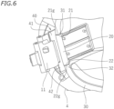
- FIG. 6 is a partial perspective view of the seat 4 to which the movable bracket 11 and the attachment component 40 are attached.
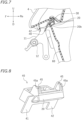
- FIG. 7 is a cross-sectional view taken along a line VII-VII in FIG. 5B .
- FIG. 8 is a perspective view in which the attachment component 40 is viewed from the rear in a vehicle front-and-rear direction and from the left in a vehicle right-and-left direction.
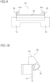
- FIG. 9 is a front view of the attachment component 40, in which the attachment component 40 is viewed from the rear in the vehicle front-and-rear direction.
- FIG. 10 is a side view of the attachment component 40, in which the attachment component 40 is viewed from the left in the vehicle right-and-left direction. As illustrated in FIG.
- the attachment component 40 includes a sealing member 20, a first cover 41, a second cover 42, and fitting portions 45.
- the attachment component 40 is formed by integrating the sealing member 20, the first cover 41, the second cover 42, and the fitting portions 45 with each other.
- the attachment component 40 is a single component.
- a material of the attachment component 40 is not limited in particular, herein, the attachment component 40 is made of rubber.
- the fitting portions 45 are provided in a pair on the right and the left.
- the movable bracket 11 is provided with a pair of protrusions 11a on the right and the left.
- fitting holes 45a into which the protrusions 11a are fitted are formed in the fitting portions 45.
- the sealing member 20 includes a first end portion 21 and a second end portion 22.
- the first end portion 31 of the sealing member 30 faces the first end portion 21 of the sealing member 20.
- the second end portion 32 of the sealing member 30 faces the second end portion 22 of the sealing member 20.
- the first end portion 21 of the sealing member 20 is arranged on the left of the vehicle center line CL, and the second end portion 22 of the sealing member 20 is arranged on the right of the vehicle center line CL (refer to FIG. 5A ).
- the sealing member 20 extends along an upper rim of the front end portion of the storage box 60. As illustrated in FIG. 5A , entireties of the sealing member 20 and the sealing member 30 form a loop on the underside of the seat 4.
- the sealing member 20 is formed into an annular shape as viewed from the side. Note that, the shape of the sealing member 20 is not limited in particular.
- the second cover 42 is arranged on the right of the first cover 41.
- the first cover 41 is arranged on the left of the vehicle center line CL
- the second cover 42 is arranged on the right of the vehicle center line CL (refer to FIG. 5B ).
- shapes of the first cover 41 and the second cover 42 are not limited in particular, herein, the first cover 41 and the second cover 42 are each formed into a shape of a flat plate that extends in the right-and-left direction and an upward-and-downward direction.
- the sealing member 20 and the sealing member 30 are separate members.
- a boundary (hereinafter, referred to as a first boundary) 21g is formed between the first end portion 21 of the sealing member 20 and the first end portion 31 of the sealing member 30, and a boundary (hereinafter, referred to as a second boundary) 22g is formed between the second end portion 22 of the sealing member 20 and the second end portion 32 of the sealing member 30.
- the first cover 41 is arranged on an outside of the storage box 60 relative to the first boundary 21g, and covers the first boundary 21g. In this case, the first cover 41 is arranged in front of the first boundary 21g, and covers a front side of the first boundary 21g.
- the first cover 41 is arranged in front of the sealing member 20 and the sealing member 30, and overlaps with the first boundary 21g as viewed from the front.
- the second cover 42 is arranged on the outside of the storage box 60 relative to the second boundary 22g, and covers the second boundary 22g.
- the second cover 42 is arranged in front of the second boundary 22g, and covers a front side of the second boundary 22g. As illustrated in FIG. 7 , the second cover 42 is arranged in front of the sealing member 20 and the sealing member 30, and overlaps with the second boundary 22g as viewed from the front.
- a lower edge 48 of the second cover 42 is located below a lower end 20b of the sealing member 20.
- the lower edge 48 of the first cover 41 is located below the lower end 20b of the sealing member 20.
- the first cover 41 and the second cover 42 extend further downward than the lower end 20b of the sealing member 20.
- the first cover 41 extends further downward than a lower end of the first boundary 21g
- the second cover 42 extends further downward than a lower end of the second boundary 22g.
- the motorcycle 1 according to this embodiment is configured as described above. Next, various advantages to be provided in this embodiment are described.
- the seat 4 is coupled to the storage box 60 by the hinge 10 in a manner that allows the seat 4 to turn.
- the sealing member 20 and the sealing member 30 are attached to the underside of the seat 4.
- the sealing member 20 and the sealing member 30 closes gaps between the seat 4 and the upper rim of the storage box 60. Ingress of rainwater and the like into the storage box 60 can be prevented by the sealing member 20 and the sealing member 30.
- the sealing member 20 and the sealing member 30 are separate members, a single sealing member to be arranged across the surface on the underside of the seat 4 and the movable bracket 11 is unnecessary. Thus, another component that allows this sealing member to be arranged across the surface on the underside of the seat 4 and the movable bracket 11 need not be added onto the movable bracket 11.
- the sealing member 20 and the sealing member 30 are separate members, the first boundary 21g and the second boundary 22g are formed between the sealing member 20 and the sealing member 30 (refer to FIG. 5B ).
- the motorcycle 1 according to this embodiment includes the first cover 41 that covers the first boundary 21g and the second cover 42 that covers the second boundary 22g. Thus, the ingress of rainwater and the like into the storage box 60 can be prevented.
- the sealing member 20, the first cover 41, and the second cover 42 which may be members separate from each other, are integrated with each other in this embodiment.
- the attachment component 40 is formed by integrating the sealing member 20, the first cover 41, and the second cover 42 with each other.
- the sealing member 20, the first cover 41, and the second cover 42 are formed of a single component. Thus, the number of components can be reduced.
- the attachment component 40 includes the fitting portions 45 to be fitted to the movable bracket 11 (refer to FIG. 8 ). By fitting the fitting portions 45 to the movable bracket 11, the attachment component 40 can be attached to the movable bracket 11. With this, the sealing member 20 can be positioned. Thus, the sealing member 20 can be easily attached to an appropriate position on the underside of the seat 4.
- the material of the sealing member 20 is not limited in particular, the sealing member 20 is made of rubber in this embodiment. With this, sealability of the sealing member 20 can be enhanced. In addition, weight of the attachment component 40 can be reduced.
- the hinge 10 is provided at the front end portion of the seat 4, and the seat 4 is turnable about the hinge shaft 13 that extends in the right-and-left direction (refer to FIG. 2 ).
- the movable bracket 11 is attached to the front end portion of the seat 4.
- the first cover 41 and the second cover 42 are arranged in front of the sealing member 20 and the sealing member 30. As viewed from the front, the first cover 41 overlaps with the boundary (first boundary) 21g between the first end portion 21 of the sealing member 20 and the first end portion 31 of the sealing member 30. As viewed from the front, the second cover 42 overlaps with the boundary (second boundary) 22g between the second end portion 22 of the sealing member 20 and the second end portion 32 of the sealing member 30.
- first cover 41 and the second cover 42 are not limited in particular, in this embodiment, the lower edge 48 of the first cover 41 and the lower edge 48 of the second cover 42 are located below the lower end 20b of the sealing member 20 (refer to FIG. 7 ).
- the first cover 41 and the second cover 42 extend further downward than the lower end 20b of the sealing member 20. With this, the ingress of rainwater, mud, and the like from below into the first boundary 21g and the second boundary 22g can be satisfactorily prevented.
- the entireties of the sealing member 20 and the sealing member 30 need not necessarily form a loop on the underside of the seat 4, these entireties form a loop (refer to FIG. 5A ) in this embodiment.
- the gaps between the seat 4 and the storage box 60 can be closed all over. With this, the ingress of rainwater, mud, and the like into the storage box 60 can be satisfactorily prevented.
- the hinge 10 is connected to the front end portion of the seat 4, and the hinge shaft 13 extends in the right-and-left direction.
- the seat 4 is configured to turn to the front.
- the position of the hinge 10 and a direction in which the seat 4 turns are not limited in particular.
- the hinge 10 may be connected to a left end portion or a right end portion of the seat 4, and the hinge shaft 13 may extend in the front-and-rear direction. In this case, the seat 4 turns to the right or the left about the hinge shaft 13.
- the sealing member 20, the first cover 41, and the second cover 42 need not necessarily be integrated with each other.
- the sealing member 20, the first cover 41, and the second cover 42 may be members separate from each other.
- the attachment component 40 need not necessarily include the fitting portions 45 to be fitted to the movable bracket 11.
- the lower edge 48 of the first cover 41 and the lower edge 48 of the second cover 42 need not necessarily be located below the lower end 20b of the sealing member 20.
- the straddled vehicle refers to a vehicle that a rider rides by straddling the same.
- the straddled vehicle is not limited to the motorcycle 1.
- the straddled vehicle may be, for example, a motor tricycle, an ATV (All Terrain vehicle), or a snowmobile.
Landscapes
- Engineering & Computer Science (AREA)
- Mechanical Engineering (AREA)
- Automatic Cycles, And Cycles In General (AREA)
- Hinges (AREA)
Abstract
Description
- The present invention relates to a straddled vehicle including a storage box that is arranged under a seat.
- Hitherto, a straddled vehicle including a seat on which a rider is seated, a storage box that is arranged under the seat and that is capable of storing a helmet and the like, and a hinge that couples the seat to the storage box in a manner that allows the seat to turn has been known (refer, for example, to
Japanese Patent Application Laid-open No. 2018-75971 - In such a straddled vehicle, the seat functions as a lid that opens and closes the storage box. Gaps are formed between the seat and an upper rim of the storage box, and hence ingress of rainwater and the like into the storage box through the gaps needs to be prevented. As a precaution, a sealing member is provided between the seat and the upper rim of the storage box.
- In order to satisfactorily close the gaps between the seat and the upper rim of the storage box, the sealing member is preferred to be provided as extensively as possible along the upper rim of the storage box, and particularly preferred to be provided all over the upper rim of the storage box. When the sealing member is attached to an underside of the seat, the sealing member is preferred to form a loop along parts that face the upper rim of the storage box among parts on the underside of the seat. However, the movable bracket of the hinge is provided on the underside of the seat. It is difficult to attach the sealing member across a surface on the underside of the seat and the movable bracket. In order that the sealing member is arranged across the surface on the underside of the seat and the movable bracket, another component needs to be added onto the movable bracket, and the sealing member needs to be attached onto the other component.
- The present invention has been made in view of such circumstances, and an object thereof is to provide a novel straddled vehicle in which a seat is supported by a hinge in a manner that allows the seat to turn relative to a storage box, and in which ingress of rainwater and the like into the storage box can be prevented with use of a sealing member to be attached to an underside of the seat.
- A straddled vehicle disclosed herein includes:
- a storage box;
- a seat that is arranged on the storage box; and
- a hinge. The hinge includes
- a movable bracket that is attached to an underside of the seat,
- a fixed bracket that is fixed to the storage box, and
- a hinge shaft that couples the movable bracket to the fixed bracket in a manner that allows the movable bracket to turn.
- The straddled vehicle includes a first sealing member and a second sealing member.
- The first sealing member
- includes
- a first end portion and
- a second end portion, and
- is attached to the movable bracket.
- The second sealing member
- includes
- a first end portion that faces the first end portion of the first sealing member and
- a second end portion that faces the second end portion of the first sealing member,
- is attached to the underside of the seat, and
- extends along an upper rim of the storage box.
- The straddled vehicle includes a first cover and a second cover.
- The first cover
- is arranged on an outside of the storage box relative to a first boundary being a boundary between the first end portion of the first sealing member and the first end portion of the second sealing member, and
- covers the first boundary.
- The second cover
- is arranged on the outside of the storage box relative to a second boundary being a boundary between the second end portion of the first sealing member and the second end portion of the second sealing member, and
- covers the second boundary.
- According to the above-described straddled vehicle, the first sealing member and the second sealing member are separate members. Thus, a single sealing member to be arranged across a surface on the underside of the seat and the movable bracket is unnecessary. Therefore, another component that allows this sealing member to be arranged across the surface on the underside of the seat and the movable bracket need not be added onto the movable bracket. Meanwhile, since the first sealing member and the second sealing member are separate members, the boundaries (the first boundary and the second boundary) are formed between the first sealing member and the second sealing member. There is a risk of ingress of rainwater and the like through these boundaries. However, the above-described straddled vehicle includes the first cover that covers the first boundary and the second cover that covers the second boundary. Thus, the ingress of rainwater and the like into the storage box can be prevented.
- The straddled vehicle may further include an attachment component that is formed by integrating the first sealing member, the first cover, and the second cover with each other.
- With this, the number of components can be reduced.
- The attachment component may include a fitting portion that is fitted to the movable bracket.
- This enables the attachment component to be attached to the movable bracket by fitting the fitting portion to the movable bracket. With this, the first sealing member can be positioned. The first sealing member can be easily attached to an appropriate position on the underside of the seat.
- The attachment component may be made of rubber.
- With this, sealability of the first sealing member can be enhanced. In addition, weight of the attachment component can be reduced.
- The movable bracket may be attached to a front end portion of the seat.
- The first cover
- may be arranged in front of the first sealing member and the second sealing member, and
- may overlap with the first boundary as viewed from the front.
- The second cover
- may be arranged in front of the first sealing member and the second sealing member, and
- may overlap with the second boundary as viewed from the front.
- With this, while the straddled vehicle is in motion, the ingress of rainwater, splashed mud from a road surface, and the like from the front into the first boundary and the second boundary can be satisfactorily prevented.
- A lower edge of the first cover and a lower edge of the second cover may be located below a lower end of the first sealing member.
- With this, the ingress of rainwater, mud, and the like from below into the first boundary and the second boundary can be satisfactorily prevented.
- Entireties of the first sealing member and the second sealing member may form a loop on the underside of the seat.
- This enables gaps between the seat and the storage box to be closed all over by the entireties of the first sealing member and the second sealing member. The ingress of rainwater and the like into the storage box can be satisfactorily prevented.
- According to the present invention, it is possible to provide the novel straddled vehicle in which a seat is supported by a hinge in a manner that allows the seat to turn relative to a storage box, and in which ingress of rainwater and the like into the storage box can be prevented with use of a sealing member to be attached to an underside of the seat.
- In the accompanying drawings:
-
FIG. 1 is a left side view of a motorcycle according to an embodiment of the present invention; -
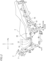
FIG. 2 is a left side view of a vehicle body frame, a seat, and a storage box; -
FIG. 3A is a bottom view of the seat; -
FIG. 3B is an enlarged view of a part IIIB inFIG. 3A ; -
FIG. 4A is a bottom view of the seat to which a movable bracket is attached; -
FIG. 4B is an enlarged view of a part IVB inFIG. 4A ; -
FIG. 5A is a bottom view of the seat to which the movable bracket and an attachment component are attached; -
FIG. 5B is an enlarged view of a part VB inFIG. 5A ; -
FIG. 6 is a partial perspective view of the seat to which the movable bracket and the attachment component are attached; -
FIG. 7 is a cross-sectional view taken along a line VII-VII inFIG. 5B ; -
FIG. 8 is a perspective view in which the attachment component is viewed from the rear in a vehicle front-and-rear direction and from the left in a vehicle right-and-left direction; -
FIG. 9 is a front view of the attachment component; and -
FIG. 10 is a side view of the attachment component. - Now, an embodiment of the present invention is described with reference to the accompanying drawings.
FIG. 1 is a left side view of a motorcycle 1 as an example of a straddled vehicle. - In the following description, unless otherwise noted, "front," "rear," "right," "left," "up," and "down" refer respectively to "front," "rear," "right," "left," "up," and "down" as viewed from an imaginary rider seated on a
seat 4 under a state in which the motorcycle 1 without the rider or luggage thereon stationarily stands upright on a horizontal plane. The reference symbols F, Re, R, L, U, and D respectively denote the "front," the "rear," the "right," the "left," the "up," and the "down." - The motorcycle 1 includes a vehicle body frame 2 (refer to
FIG. 2 ) that includes ahead pipe 3, theseat 4 on which the rider is seated, a storage box 60 (refer toFIG. 2 ) that is arranged under theseat 4, a travellingdrive source 7 that is constituted by an internal combustion engine or an electric motor, afront wheel 6, arear wheel 8, afront cover 52, and right and left side covers 53. A steeringshaft 5 is supported by thehead pipe 3 in a manner that allows thesteering shaft 5 to turn to the right and the left. Handle bars 9 are fixed to thesteering shaft 5. In addition, afront fork 51 is fixed to thesteering shaft 5. Thefront wheel 6 is supported by thefront fork 51 in a manner that allows thefront wheel 6 to rotate. - As illustrated in
FIG. 2 , thevehicle body frame 2 includes amain frame 55 that extends rearward from thehead pipe 3, and aseat frame 56 that extends rearward from themain frame 55. Theseat 4 and thestorage box 60 are supported by theseat frame 56. - The
storage box 60 is formed into a shape of a box opened upward. Thestorage box 60 has abottom wall 61 and aperipheral wall 62 that extends upward from an outer peripheral portion of thebottom wall 61. An upper end portion of theperipheral wall 62 serves as an upper rim of thestorage box 60. - The
seat 4 is arranged on thestorage box 60. Theseat 4 is coupled to thestorage box 60 with ahinge 10. Thehinge 10 is connected to a front end portion of theseat 4 and a front end portion of thestorage box 60. Theseat 4 is turnable relative to thestorage box 60. Theseat 4 has a function to support the rider and a function of a lid of thestorage box 60. - The
hinge 10 includes amovable bracket 11 that is attached to an underside of theseat 4, a fixedbracket 12 that is provided to thevehicle body frame 2, and ahinge shaft 13 that couples themovable bracket 11 and the fixedbracket 12 to each other in a manner that allows themovable bracket 11 and the fixedbracket 12 to turn relative to each other. Theseat 4 is turnable about thehinge shaft 13. When theseat 4 is closed as illustrated inFIG. 2 , thestorage box 60 is shut by theseat 4. In this state, the rider can be seated on theseat 4. When theseat 4 in the state illustrated inFIG. 2 is turned counterclockwise about thehinge shaft 13, an upper side of thestorage box 60 is opened. In this state, items can be put into and taken out of thestorage box 60. Note that, thestorage box 60 is fixed to thevehicle body frame 2. Thus, the fixedbracket 12 is fixed to thestorage box 60 through intermediation of thevehicle body frame 2. The fixedbracket 12 may be fixed directly to thestorage box 60, or the fixedbracket 12 may be indirectly fixed as in this embodiment. -
FIG. 3A is a bottom view of theseat 4.FIG. 3B is an enlarged view of a part IIIB inFIG. 3A . As illustrated inFIG. 3A , a sealingmember 30 is attached to the underside of theseat 4. The sealingmember 30 is formed into a strip shape. On a surface on the underside of theseat 4, the sealingmember 30 is arranged at a part that faces the upper rim of thestorage box 60. The sealingmember 30 does not form a loop, and is discontinued at the front end portion of theseat 4. The sealingmember 30 includes afirst end portion 31 and asecond end portion 32. Thefirst end portion 31 and thesecond end portion 32 are located at the front end portion of theseat 4. Thefirst end portion 31 is arranged on the left of a vehicle center line CL, and thesecond end portion 32 is arranged on the right of the vehicle center line CL. Although a material of the sealingmember 30 is not limited in particular, the sealingmember 30 is made of rubber in this embodiment. -
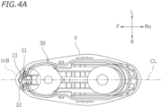
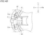
FIG. 4A is a bottom view of theseat 4 to which themovable bracket 11 is attached.FIG. 4B is an enlarged view of a part IVB inFIG. 4A . As illustrated inFIG. 4B , themovable bracket 11 is attached to the front end portion of theseat 4. A part of themovable bracket 11 is arranged between thefirst end portion 31 and thesecond end portion 32 of the sealingmember 30. The sealingmember 30 is not arranged over themovable bracket 11. The sealingmember 30 is not provided across themovable bracket 11. - As illustrated in
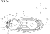
FIG. 5A andFIG. 5B , anattachment component 40 is attached onto themovable bracket 11.FIG. 5A is a bottom view of theseat 4 to which themovable bracket 11 and theattachment component 40 are attached.FIG. 5B is an enlarged view of a part VB inFIG. 5A . As illustrated inFIG. 5B , a part of theattachment component 40 is arranged between thefirst end portion 31 and thesecond end portion 32 of the sealingmember 30. -
FIG. 6 is a partial perspective view of theseat 4 to which themovable bracket 11 and theattachment component 40 are attached.FIG. 7 is a cross-sectional view taken along a line VII-VII inFIG. 5B .FIG. 8 is a perspective view in which theattachment component 40 is viewed from the rear in a vehicle front-and-rear direction and from the left in a vehicle right-and-left direction.FIG. 9 is a front view of theattachment component 40, in which theattachment component 40 is viewed from the rear in the vehicle front-and-rear direction.FIG. 10 is a side view of theattachment component 40, in which theattachment component 40 is viewed from the left in the vehicle right-and-left direction. As illustrated inFIG. 8 , theattachment component 40 includes a sealingmember 20, afirst cover 41, asecond cover 42, andfitting portions 45. In this embodiment, theattachment component 40 is formed by integrating the sealingmember 20, thefirst cover 41, thesecond cover 42, and thefitting portions 45 with each other. Theattachment component 40 is a single component. Although a material of theattachment component 40 is not limited in particular, herein, theattachment component 40 is made of rubber. - Although a configuration of the
fitting portions 45 is not limited in particular, in this embodiment, thefitting portions 45 are provided in a pair on the right and the left. As illustrated inFIG. 4B , themovable bracket 11 is provided with a pair ofprotrusions 11a on the right and the left. As illustrated inFIG. 9 ,fitting holes 45a into which theprotrusions 11a are fitted are formed in thefitting portions 45. By fitting theprotrusions 11a into thefitting holes 45a, theattachment component 40 is attached to themovable bracket 11, and theattachment component 40 is positioned relative to themovable bracket 11. By fitting thefitting holes 45a to theprotrusions 11a, theattachment component 40 can be attached at an appropriate position on themovable bracket 11. - As illustrated in
FIG. 6 , the sealingmember 20 includes afirst end portion 21 and asecond end portion 22. Thefirst end portion 31 of the sealingmember 30 faces thefirst end portion 21 of the sealingmember 20. Thesecond end portion 32 of the sealingmember 30 faces thesecond end portion 22 of the sealingmember 20. Thefirst end portion 21 of the sealingmember 20 is arranged on the left of the vehicle center line CL, and thesecond end portion 22 of the sealingmember 20 is arranged on the right of the vehicle center line CL (refer toFIG. 5A ). Although not shown, the sealingmember 20 extends along an upper rim of the front end portion of thestorage box 60. As illustrated inFIG. 5A , entireties of the sealingmember 20 and the sealingmember 30 form a loop on the underside of theseat 4. The entireties of the sealingmember 20 and the sealingmember 30 are arranged all over the upper rim of thestorage box 60. As illustrated inFIG. 10 , the sealingmember 20 is formed into an annular shape as viewed from the side. Note that, the shape of the sealingmember 20 is not limited in particular. - As illustrated in
FIG. 9 , thesecond cover 42 is arranged on the right of thefirst cover 41. Thefirst cover 41 is arranged on the left of the vehicle center line CL, and thesecond cover 42 is arranged on the right of the vehicle center line CL (refer toFIG. 5B ). Although shapes of thefirst cover 41 and thesecond cover 42 are not limited in particular, herein, thefirst cover 41 and thesecond cover 42 are each formed into a shape of a flat plate that extends in the right-and-left direction and an upward-and-downward direction. - As illustrated in
FIG. 6 , the sealingmember 20 and the sealingmember 30 are separate members. Thus, a boundary (hereinafter, referred to as a first boundary) 21g is formed between thefirst end portion 21 of the sealingmember 20 and thefirst end portion 31 of the sealingmember 30, and a boundary (hereinafter, referred to as a second boundary) 22g is formed between thesecond end portion 22 of the sealingmember 20 and thesecond end portion 32 of the sealingmember 30. Thefirst cover 41 is arranged on an outside of thestorage box 60 relative to thefirst boundary 21g, and covers thefirst boundary 21g. In this case, thefirst cover 41 is arranged in front of thefirst boundary 21g, and covers a front side of thefirst boundary 21g. Thefirst cover 41 is arranged in front of the sealingmember 20 and the sealingmember 30, and overlaps with thefirst boundary 21g as viewed from the front. Thesecond cover 42 is arranged on the outside of thestorage box 60 relative to thesecond boundary 22g, and covers thesecond boundary 22g. Thesecond cover 42 is arranged in front of thesecond boundary 22g, and covers a front side of thesecond boundary 22g. As illustrated inFIG. 7 , thesecond cover 42 is arranged in front of the sealingmember 20 and the sealingmember 30, and overlaps with thesecond boundary 22g as viewed from the front. - As illustrated in
FIG. 7 , alower edge 48 of thesecond cover 42 is located below alower end 20b of the sealingmember 20. Similarly, thelower edge 48 of thefirst cover 41 is located below thelower end 20b of the sealingmember 20. In other words, thefirst cover 41 and thesecond cover 42 extend further downward than thelower end 20b of the sealingmember 20. Thefirst cover 41 extends further downward than a lower end of thefirst boundary 21g, and thesecond cover 42 extends further downward than a lower end of thesecond boundary 22g. - The motorcycle 1 according to this embodiment is configured as described above. Next, various advantages to be provided in this embodiment are described.
- According to this embodiment, as illustrated in
FIG. 2 , theseat 4 is coupled to thestorage box 60 by thehinge 10 in a manner that allows theseat 4 to turn. As illustrated inFIG. 5A , the sealingmember 20 and the sealingmember 30 are attached to the underside of theseat 4. The sealingmember 20 and the sealingmember 30 closes gaps between theseat 4 and the upper rim of thestorage box 60. Ingress of rainwater and the like into thestorage box 60 can be prevented by the sealingmember 20 and the sealingmember 30. - According to this embodiment, since the sealing
member 20 and the sealingmember 30 are separate members, a single sealing member to be arranged across the surface on the underside of theseat 4 and themovable bracket 11 is unnecessary. Thus, another component that allows this sealing member to be arranged across the surface on the underside of theseat 4 and themovable bracket 11 need not be added onto themovable bracket 11. Meanwhile, since the sealingmember 20 and the sealingmember 30 are separate members, thefirst boundary 21g and thesecond boundary 22g are formed between the sealingmember 20 and the sealing member 30 (refer toFIG. 5B ). There is a risk of the ingress of rainwater and the like through theseboundaries first cover 41 that covers thefirst boundary 21g and thesecond cover 42 that covers thesecond boundary 22g. Thus, the ingress of rainwater and the like into thestorage box 60 can be prevented. - The sealing
member 20, thefirst cover 41, and thesecond cover 42, which may be members separate from each other, are integrated with each other in this embodiment. Theattachment component 40 is formed by integrating the sealingmember 20, thefirst cover 41, and thesecond cover 42 with each other. The sealingmember 20, thefirst cover 41, and thesecond cover 42 are formed of a single component. Thus, the number of components can be reduced. - According to this embodiment, the
attachment component 40 includes thefitting portions 45 to be fitted to the movable bracket 11 (refer toFIG. 8 ). By fitting thefitting portions 45 to themovable bracket 11, theattachment component 40 can be attached to themovable bracket 11. With this, the sealingmember 20 can be positioned. Thus, the sealingmember 20 can be easily attached to an appropriate position on the underside of theseat 4. - Although the material of the sealing
member 20 is not limited in particular, the sealingmember 20 is made of rubber in this embodiment. With this, sealability of the sealingmember 20 can be enhanced. In addition, weight of theattachment component 40 can be reduced. - In this embodiment, the
hinge 10 is provided at the front end portion of theseat 4, and theseat 4 is turnable about thehinge shaft 13 that extends in the right-and-left direction (refer toFIG. 2 ). Themovable bracket 11 is attached to the front end portion of theseat 4. Thefirst cover 41 and thesecond cover 42 are arranged in front of the sealingmember 20 and the sealingmember 30. As viewed from the front, thefirst cover 41 overlaps with the boundary (first boundary) 21g between thefirst end portion 21 of the sealingmember 20 and thefirst end portion 31 of the sealingmember 30. As viewed from the front, thesecond cover 42 overlaps with the boundary (second boundary) 22g between thesecond end portion 22 of the sealingmember 20 and thesecond end portion 32 of the sealingmember 30. With this, the ingress of rainwater and the like from the front into thefirst boundary 21g and thesecond boundary 22g can be satisfactorily prevented. In addition, also when the motorcycle 1 in motion kicks up and splashes mud and the like on a road surface to the rear, ingress of such mud and the like into thefirst boundary 21g and thesecond boundary 22g can be satisfactorily prevented. In this way, the ingress of rainwater, mud, and the like into thestorage box 60 through thefirst boundary 21g and thesecond boundary 22g can be satisfactorily prevented. - Although dimensions of the
first cover 41 and thesecond cover 42 are not limited in particular, in this embodiment, thelower edge 48 of thefirst cover 41 and thelower edge 48 of thesecond cover 42 are located below thelower end 20b of the sealing member 20 (refer toFIG. 7 ). Thefirst cover 41 and thesecond cover 42 extend further downward than thelower end 20b of the sealingmember 20. With this, the ingress of rainwater, mud, and the like from below into thefirst boundary 21g and thesecond boundary 22g can be satisfactorily prevented. - Although the entireties of the sealing
member 20 and the sealingmember 30 need not necessarily form a loop on the underside of theseat 4, these entireties form a loop (refer toFIG. 5A ) in this embodiment. Thus, the gaps between theseat 4 and thestorage box 60 can be closed all over. With this, the ingress of rainwater, mud, and the like into thestorage box 60 can be satisfactorily prevented. - Although an embodiment is described above, this embodiment is merely an example. Various other embodiments may be implemented.
- In the above-described embodiment, the
hinge 10 is connected to the front end portion of theseat 4, and thehinge shaft 13 extends in the right-and-left direction. Theseat 4 is configured to turn to the front. However, the position of thehinge 10 and a direction in which theseat 4 turns are not limited in particular. For example, thehinge 10 may be connected to a left end portion or a right end portion of theseat 4, and thehinge shaft 13 may extend in the front-and-rear direction. In this case, theseat 4 turns to the right or the left about thehinge shaft 13. - The sealing
member 20, thefirst cover 41, and thesecond cover 42 need not necessarily be integrated with each other. For example, the sealingmember 20, thefirst cover 41, and thesecond cover 42 may be members separate from each other. - The
attachment component 40 need not necessarily include thefitting portions 45 to be fitted to themovable bracket 11. - The
lower edge 48 of thefirst cover 41 and thelower edge 48 of thesecond cover 42 need not necessarily be located below thelower end 20b of the sealingmember 20. - The straddled vehicle refers to a vehicle that a rider rides by straddling the same. The straddled vehicle is not limited to the motorcycle 1. The straddled vehicle may be, for example, a motor tricycle, an ATV (All Terrain vehicle), or a snowmobile.
-
- 1
- motorcycle (straddled vehicle)
- 4
- seat
- 10
- hinge
- 11
- movable bracket
- 12
- fixed bracket
- 13
- hinge shaft
- 20
- sealing member (first sealing member)
- 21
- first end portion
- 21g
- first boundary
- 22
- second end portion
- 22g
- second boundary
- 30
- sealing member (second sealing member)
- 31
- first end portion
- 32
- second end portion
- 40
- attachment component
- 41
- first cover
- 42
- second cover
- 45
- fitting portion
- 60
- storage box
Claims (7)
- A straddled vehicle (1), comprising:a storage box (60);a seat (4) that is arranged on the storage box (60);a hinge (10) that includesa movable bracket (11) that is attached to an underside of the seat (4),a fixed bracket (12) that is fixed to the storage box (60), anda hinge shaft (13) that couples the movable bracket (11) to the fixed bracket (12) in a manner that allows the movable bracket (11) to turn;a first sealing member (20)that includesa first end portion (21) anda second end portion (22), andthat is attached to the movable bracket (11);a second sealing member (30)that includesa first end portion (31) which faces the first end portion (21) of the first sealing member (20) anda second end portion (32) which faces the second end portion (22) of the first sealing member (20),that is attached to the underside of the seat (4), andthat extends along an upper rim of the storage box (60) ;a first cover (41)that is arranged on an outside of the storage box (60) relative to a first boundary (21g) being a boundary between the first end portion (21) of the first sealing member (20) and the first end portion (31) of the second sealing member (30), andthat covers the first boundary (21g); anda second cover (42)that is arranged on the outside of the storage box (60) relative to a second boundary (22g) being a boundary between the second end portion (22) of the first sealing member (20) and the second end portion (32) of the second sealing member (30), andthat covers the second boundary (22g).
- The straddled vehicle (1) according to Claim 1, further comprising
an attachment component (40) that is formed by integrating the first sealing member (20), the first cover (41), and the second cover (42) with each other. - The straddled vehicle (1) according to Claim 2,
wherein the attachment component (40) includes a fitting portion (45) that is fitted to the movable bracket (11). - The straddled vehicle (1) according to Claim 2 or 3,
wherein the attachment component (40) is made of rubber. - The straddled vehicle (1) according to any one of Claims 1 to 4,wherein the movable bracket (11) is attached to a front end portion of the seat (4),wherein the first cover (41)is arranged in front of the first sealing member (20) and the second sealing member (30), andoverlaps with the first boundary (21g) as viewed from the front, andwherein the second cover (42)is arranged in front of the first sealing member (20) and the second sealing member (30), andoverlaps with the second boundary (22g) as viewed from the front.
- The straddled vehicle (1) according to any one of Claims 1 to 5,
wherein a lower edge (48) of the first cover (41) and a lower edge (48) of the second cover (42) are located below a lower end (20b) of the first sealing member (20). - The straddled vehicle (1) according to any one of Claims 1 to 6,
wherein entireties of the first sealing member (20) and the second sealing member (30) form a loop on the underside of the seat (4) .
Applications Claiming Priority (1)
| Application Number | Priority Date | Filing Date | Title |
|---|---|---|---|
| JP2022096355A JP2023183007A (en) | 2022-06-15 | 2022-06-15 | saddle type vehicle |
Publications (2)
| Publication Number | Publication Date |
|---|---|
| EP4292915A1 true EP4292915A1 (en) | 2023-12-20 |
| EP4292915B1 EP4292915B1 (en) | 2024-08-28 |
Family
ID=86609895
Family Applications (1)
| Application Number | Title | Priority Date | Filing Date |
|---|---|---|---|
| EP23175985.3A Active EP4292915B1 (en) | 2022-06-15 | 2023-05-30 | Storage box below seat of an straddled vehicle |
Country Status (3)
| Country | Link |
|---|---|
| EP (1) | EP4292915B1 (en) |
| JP (1) | JP2023183007A (en) |
| PH (1) | PH12023050280A1 (en) |
Citations (3)
| Publication number | Priority date | Publication date | Assignee | Title |
|---|---|---|---|---|
| JP2013060082A (en) * | 2011-09-13 | 2013-04-04 | Honda Motor Co Ltd | Mobile terminal support structure for straddle type vehicle |
| EP3321157A1 (en) * | 2016-11-09 | 2018-05-16 | Yamaha Hatsudoki Kabushiki Kaisha | Straddled vehicle |
| EP3381783A1 (en) * | 2017-03-31 | 2018-10-03 | Honda Motor Co., Ltd. | Seat catch mounting structure of straddle type vehicle |
-
2022
- 2022-06-15 JP JP2022096355A patent/JP2023183007A/en active Pending
-
2023
- 2023-05-30 EP EP23175985.3A patent/EP4292915B1/en active Active
- 2023-06-14 PH PH1/2023/050280A patent/PH12023050280A1/en unknown
Patent Citations (4)
| Publication number | Priority date | Publication date | Assignee | Title |
|---|---|---|---|---|
| JP2013060082A (en) * | 2011-09-13 | 2013-04-04 | Honda Motor Co Ltd | Mobile terminal support structure for straddle type vehicle |
| EP3321157A1 (en) * | 2016-11-09 | 2018-05-16 | Yamaha Hatsudoki Kabushiki Kaisha | Straddled vehicle |
| JP2018075971A (en) | 2016-11-09 | 2018-05-17 | ヤマハ発動機株式会社 | Saddle riding vehicle |
| EP3381783A1 (en) * | 2017-03-31 | 2018-10-03 | Honda Motor Co., Ltd. | Seat catch mounting structure of straddle type vehicle |
Also Published As
| Publication number | Publication date |
|---|---|
| PH12023050280A1 (en) | 2024-03-11 |
| EP4292915B1 (en) | 2024-08-28 |
| JP2023183007A (en) | 2023-12-27 |
Similar Documents
| Publication | Publication Date | Title |
|---|---|---|
| EP1939078B1 (en) | Motorcycle | |
| JP2012254771A (en) | Front structure of straddle type vehicle | |
| JP2005306060A (en) | Saddle riding vehicle | |
| EP4292915B1 (en) | Storage box below seat of an straddled vehicle | |
| EP3150474B1 (en) | Battery compartment for saddle-type vehicle | |
| EP3381783B1 (en) | Seat catch mounting structure of straddle type vehicle | |
| US8573667B2 (en) | Cover structure of saddle ride type vehicle | |
| JP4334062B2 (en) | Fuel tank seal structure for motorcycle fuel tank | |
| JP5869889B2 (en) | Saddle riding vehicle | |
| CN115066367B (en) | Tail cover assembly for saddle-type vehicle | |
| JP5661539B2 (en) | Seat structure of saddle riding type vehicle | |
| US9381966B2 (en) | Vehicle | |
| EP2878523B1 (en) | Straddle-type vehicle | |
| JP7566167B2 (en) | Tank cover seal structure | |
| JP3991631B2 (en) | Saddle-type vehicle storage container | |
| EP3929014B1 (en) | Fuel tank cap of a straddled vehicle | |
| JP6782142B2 (en) | Loading basket mounting structure | |
| JP7733635B2 (en) | Storage box for saddle-type vehicles | |
| JP7470723B2 (en) | Saddle type vehicle | |
| JP7733634B2 (en) | Saddle-type vehicle | |
| JP4847904B2 (en) | Motorcycle fuel tank | |
| JP7357167B2 (en) | Body cover structure for saddle-type vehicles | |
| JPS633913Y2 (en) | ||
| US20190039672A1 (en) | Saddle-type vehicle | |
| JP2009006993A (en) | vehicle |
Legal Events
| Date | Code | Title | Description |
|---|---|---|---|
| PUAI | Public reference made under article 153(3) epc to a published international application that has entered the european phase |
Free format text: ORIGINAL CODE: 0009012 |
|
| STAA | Information on the status of an ep patent application or granted ep patent |
Free format text: STATUS: THE APPLICATION HAS BEEN PUBLISHED |
|
| STAA | Information on the status of an ep patent application or granted ep patent |
Free format text: STATUS: REQUEST FOR EXAMINATION WAS MADE |
|
| AK | Designated contracting states |
Kind code of ref document: A1 Designated state(s): AL AT BE BG CH CY CZ DE DK EE ES FI FR GB GR HR HU IE IS IT LI LT LU LV MC ME MK MT NL NO PL PT RO RS SE SI SK SM TR |
|
| 17P | Request for examination filed |
Effective date: 20231206 |
|
| RBV | Designated contracting states (corrected) |
Designated state(s): AL AT BE BG CH CY CZ DE DK EE ES FI FR GB GR HR HU IE IS IT LI LT LU LV MC ME MK MT NL NO PL PT RO RS SE SI SK SM TR |
|
| RIC1 | Information provided on ipc code assigned before grant |
Ipc: B62J 9/14 20200101AFI20240207BHEP |
|
| GRAP | Despatch of communication of intention to grant a patent |
Free format text: ORIGINAL CODE: EPIDOSNIGR1 |
|
| STAA | Information on the status of an ep patent application or granted ep patent |
Free format text: STATUS: GRANT OF PATENT IS INTENDED |
|
| RIC1 | Information provided on ipc code assigned before grant |
Ipc: B62J 1/12 20060101ALI20240220BHEP Ipc: B62J 9/14 20200101AFI20240220BHEP |
|
| INTG | Intention to grant announced |
Effective date: 20240320 |
|
| GRAS | Grant fee paid |
Free format text: ORIGINAL CODE: EPIDOSNIGR3 |
|
| GRAA | (expected) grant |
Free format text: ORIGINAL CODE: 0009210 |
|
| STAA | Information on the status of an ep patent application or granted ep patent |
Free format text: STATUS: THE PATENT HAS BEEN GRANTED |
|
| AK | Designated contracting states |
Kind code of ref document: B1 Designated state(s): AL AT BE BG CH CY CZ DE DK EE ES FI FR GB GR HR HU IE IS IT LI LT LU LV MC ME MK MT NL NO PL PT RO RS SE SI SK SM TR |
|
| RAP3 | Party data changed (applicant data changed or rights of an application transferred) |
Owner name: YAMAHA HATSUDOKI KABUSHIKI KAISHA |
|
| REG | Reference to a national code |
Ref country code: CH Ref legal event code: EP |
|
| REG | Reference to a national code |
Ref country code: DE Ref legal event code: R096 Ref document number: 602023000460 Country of ref document: DE |
|
| P01 | Opt-out of the competence of the unified patent court (upc) registered |
Free format text: CASE NUMBER: APP_47764/2024 Effective date: 20240820 |
|
| REG | Reference to a national code |
Ref country code: IE Ref legal event code: FG4D |
|
| REG | Reference to a national code |
Ref country code: LT Ref legal event code: MG9D |
|
| PG25 | Lapsed in a contracting state [announced via postgrant information from national office to epo] |
Ref country code: NO Free format text: LAPSE BECAUSE OF FAILURE TO SUBMIT A TRANSLATION OF THE DESCRIPTION OR TO PAY THE FEE WITHIN THE PRESCRIBED TIME-LIMIT Effective date: 20241128 |
|
| REG | Reference to a national code |
Ref country code: AT Ref legal event code: MK05 Ref document number: 1717675 Country of ref document: AT Kind code of ref document: T Effective date: 20240828 |
|
| PG25 | Lapsed in a contracting state [announced via postgrant information from national office to epo] |
Ref country code: PL Free format text: LAPSE BECAUSE OF FAILURE TO SUBMIT A TRANSLATION OF THE DESCRIPTION OR TO PAY THE FEE WITHIN THE PRESCRIBED TIME-LIMIT Effective date: 20240828 Ref country code: NL Free format text: LAPSE BECAUSE OF FAILURE TO SUBMIT A TRANSLATION OF THE DESCRIPTION OR TO PAY THE FEE WITHIN THE PRESCRIBED TIME-LIMIT Effective date: 20240828 Ref country code: GR Free format text: LAPSE BECAUSE OF FAILURE TO SUBMIT A TRANSLATION OF THE DESCRIPTION OR TO PAY THE FEE WITHIN THE PRESCRIBED TIME-LIMIT Effective date: 20241129 Ref country code: FI Free format text: LAPSE BECAUSE OF FAILURE TO SUBMIT A TRANSLATION OF THE DESCRIPTION OR TO PAY THE FEE WITHIN THE PRESCRIBED TIME-LIMIT Effective date: 20240828 Ref country code: PT Free format text: LAPSE BECAUSE OF FAILURE TO SUBMIT A TRANSLATION OF THE DESCRIPTION OR TO PAY THE FEE WITHIN THE PRESCRIBED TIME-LIMIT Effective date: 20241230 |
|
| PG25 | Lapsed in a contracting state [announced via postgrant information from national office to epo] |
Ref country code: BG Free format text: LAPSE BECAUSE OF FAILURE TO SUBMIT A TRANSLATION OF THE DESCRIPTION OR TO PAY THE FEE WITHIN THE PRESCRIBED TIME-LIMIT Effective date: 20240828 |
|
| PG25 | Lapsed in a contracting state [announced via postgrant information from national office to epo] |
Ref country code: LV Free format text: LAPSE BECAUSE OF FAILURE TO SUBMIT A TRANSLATION OF THE DESCRIPTION OR TO PAY THE FEE WITHIN THE PRESCRIBED TIME-LIMIT Effective date: 20240828 |
|
| REG | Reference to a national code |
Ref country code: NL Ref legal event code: MP Effective date: 20240828 |
|
| PG25 | Lapsed in a contracting state [announced via postgrant information from national office to epo] |
Ref country code: AT Free format text: LAPSE BECAUSE OF FAILURE TO SUBMIT A TRANSLATION OF THE DESCRIPTION OR TO PAY THE FEE WITHIN THE PRESCRIBED TIME-LIMIT Effective date: 20240828 Ref country code: IS Free format text: LAPSE BECAUSE OF FAILURE TO SUBMIT A TRANSLATION OF THE DESCRIPTION OR TO PAY THE FEE WITHIN THE PRESCRIBED TIME-LIMIT Effective date: 20241228 |
|
| PG25 | Lapsed in a contracting state [announced via postgrant information from national office to epo] |
Ref country code: HR Free format text: LAPSE BECAUSE OF FAILURE TO SUBMIT A TRANSLATION OF THE DESCRIPTION OR TO PAY THE FEE WITHIN THE PRESCRIBED TIME-LIMIT Effective date: 20240828 |
|
| PG25 | Lapsed in a contracting state [announced via postgrant information from national office to epo] |
Ref country code: RS Free format text: LAPSE BECAUSE OF FAILURE TO SUBMIT A TRANSLATION OF THE DESCRIPTION OR TO PAY THE FEE WITHIN THE PRESCRIBED TIME-LIMIT Effective date: 20241128 Ref country code: ES Free format text: LAPSE BECAUSE OF FAILURE TO SUBMIT A TRANSLATION OF THE DESCRIPTION OR TO PAY THE FEE WITHIN THE PRESCRIBED TIME-LIMIT Effective date: 20240828 |
|
| PG25 | Lapsed in a contracting state [announced via postgrant information from national office to epo] |
Ref country code: RS Free format text: LAPSE BECAUSE OF FAILURE TO SUBMIT A TRANSLATION OF THE DESCRIPTION OR TO PAY THE FEE WITHIN THE PRESCRIBED TIME-LIMIT Effective date: 20241128 Ref country code: PT Free format text: LAPSE BECAUSE OF FAILURE TO SUBMIT A TRANSLATION OF THE DESCRIPTION OR TO PAY THE FEE WITHIN THE PRESCRIBED TIME-LIMIT Effective date: 20241230 Ref country code: PL Free format text: LAPSE BECAUSE OF FAILURE TO SUBMIT A TRANSLATION OF THE DESCRIPTION OR TO PAY THE FEE WITHIN THE PRESCRIBED TIME-LIMIT Effective date: 20240828 Ref country code: NO Free format text: LAPSE BECAUSE OF FAILURE TO SUBMIT A TRANSLATION OF THE DESCRIPTION OR TO PAY THE FEE WITHIN THE PRESCRIBED TIME-LIMIT Effective date: 20241128 Ref country code: NL Free format text: LAPSE BECAUSE OF FAILURE TO SUBMIT A TRANSLATION OF THE DESCRIPTION OR TO PAY THE FEE WITHIN THE PRESCRIBED TIME-LIMIT Effective date: 20240828 Ref country code: LV Free format text: LAPSE BECAUSE OF FAILURE TO SUBMIT A TRANSLATION OF THE DESCRIPTION OR TO PAY THE FEE WITHIN THE PRESCRIBED TIME-LIMIT Effective date: 20240828 Ref country code: IS Free format text: LAPSE BECAUSE OF FAILURE TO SUBMIT A TRANSLATION OF THE DESCRIPTION OR TO PAY THE FEE WITHIN THE PRESCRIBED TIME-LIMIT Effective date: 20241228 Ref country code: HR Free format text: LAPSE BECAUSE OF FAILURE TO SUBMIT A TRANSLATION OF THE DESCRIPTION OR TO PAY THE FEE WITHIN THE PRESCRIBED TIME-LIMIT Effective date: 20240828 Ref country code: GR Free format text: LAPSE BECAUSE OF FAILURE TO SUBMIT A TRANSLATION OF THE DESCRIPTION OR TO PAY THE FEE WITHIN THE PRESCRIBED TIME-LIMIT Effective date: 20241129 Ref country code: FI Free format text: LAPSE BECAUSE OF FAILURE TO SUBMIT A TRANSLATION OF THE DESCRIPTION OR TO PAY THE FEE WITHIN THE PRESCRIBED TIME-LIMIT Effective date: 20240828 Ref country code: ES Free format text: LAPSE BECAUSE OF FAILURE TO SUBMIT A TRANSLATION OF THE DESCRIPTION OR TO PAY THE FEE WITHIN THE PRESCRIBED TIME-LIMIT Effective date: 20240828 Ref country code: BG Free format text: LAPSE BECAUSE OF FAILURE TO SUBMIT A TRANSLATION OF THE DESCRIPTION OR TO PAY THE FEE WITHIN THE PRESCRIBED TIME-LIMIT Effective date: 20240828 Ref country code: AT Free format text: LAPSE BECAUSE OF FAILURE TO SUBMIT A TRANSLATION OF THE DESCRIPTION OR TO PAY THE FEE WITHIN THE PRESCRIBED TIME-LIMIT Effective date: 20240828 |
|
| PG25 | Lapsed in a contracting state [announced via postgrant information from national office to epo] |
Ref country code: RO Free format text: LAPSE BECAUSE OF FAILURE TO SUBMIT A TRANSLATION OF THE DESCRIPTION OR TO PAY THE FEE WITHIN THE PRESCRIBED TIME-LIMIT Effective date: 20240828 Ref country code: SM Free format text: LAPSE BECAUSE OF FAILURE TO SUBMIT A TRANSLATION OF THE DESCRIPTION OR TO PAY THE FEE WITHIN THE PRESCRIBED TIME-LIMIT Effective date: 20240828 Ref country code: DK Free format text: LAPSE BECAUSE OF FAILURE TO SUBMIT A TRANSLATION OF THE DESCRIPTION OR TO PAY THE FEE WITHIN THE PRESCRIBED TIME-LIMIT Effective date: 20240828 |
|
| PG25 | Lapsed in a contracting state [announced via postgrant information from national office to epo] |
Ref country code: EE Free format text: LAPSE BECAUSE OF FAILURE TO SUBMIT A TRANSLATION OF THE DESCRIPTION OR TO PAY THE FEE WITHIN THE PRESCRIBED TIME-LIMIT Effective date: 20240828 |
|
| PG25 | Lapsed in a contracting state [announced via postgrant information from national office to epo] |
Ref country code: CZ Free format text: LAPSE BECAUSE OF FAILURE TO SUBMIT A TRANSLATION OF THE DESCRIPTION OR TO PAY THE FEE WITHIN THE PRESCRIBED TIME-LIMIT Effective date: 20240828 |
|
| PG25 | Lapsed in a contracting state [announced via postgrant information from national office to epo] |
Ref country code: SK Free format text: LAPSE BECAUSE OF FAILURE TO SUBMIT A TRANSLATION OF THE DESCRIPTION OR TO PAY THE FEE WITHIN THE PRESCRIBED TIME-LIMIT Effective date: 20240828 |
|
| REG | Reference to a national code |
Ref country code: DE Ref legal event code: R097 Ref document number: 602023000460 Country of ref document: DE |
|
| PLBE | No opposition filed within time limit |
Free format text: ORIGINAL CODE: 0009261 |
|
| STAA | Information on the status of an ep patent application or granted ep patent |
Free format text: STATUS: NO OPPOSITION FILED WITHIN TIME LIMIT |
|
| PGFP | Annual fee paid to national office [announced via postgrant information from national office to epo] |
Ref country code: DE Payment date: 20250521 Year of fee payment: 3 |
|
| PGFP | Annual fee paid to national office [announced via postgrant information from national office to epo] |
Ref country code: IT Payment date: 20250531 Year of fee payment: 3 |
|
| PGFP | Annual fee paid to national office [announced via postgrant information from national office to epo] |
Ref country code: FR Payment date: 20250528 Year of fee payment: 3 |
|
| 26N | No opposition filed |
Effective date: 20250530 |
|
| PG25 | Lapsed in a contracting state [announced via postgrant information from national office to epo] |
Ref country code: SE Free format text: LAPSE BECAUSE OF FAILURE TO SUBMIT A TRANSLATION OF THE DESCRIPTION OR TO PAY THE FEE WITHIN THE PRESCRIBED TIME-LIMIT Effective date: 20240828 |
|
| PG25 | Lapsed in a contracting state [announced via postgrant information from national office to epo] |
Ref country code: LU Free format text: LAPSE BECAUSE OF NON-PAYMENT OF DUE FEES Effective date: 20250530 |
|
| REG | Reference to a national code |
Ref country code: BE Ref legal event code: MM Effective date: 20250531 |
|
| PG25 | Lapsed in a contracting state [announced via postgrant information from national office to epo] |
Ref country code: MC Free format text: LAPSE BECAUSE OF FAILURE TO SUBMIT A TRANSLATION OF THE DESCRIPTION OR TO PAY THE FEE WITHIN THE PRESCRIBED TIME-LIMIT Effective date: 20240828 |
|
| PG25 | Lapsed in a contracting state [announced via postgrant information from national office to epo] |
Ref country code: IE Free format text: LAPSE BECAUSE OF NON-PAYMENT OF DUE FEES Effective date: 20250530 |
|
| PG25 | Lapsed in a contracting state [announced via postgrant information from national office to epo] |
Ref country code: BE Free format text: LAPSE BECAUSE OF NON-PAYMENT OF DUE FEES Effective date: 20250531 |