EP4292907A1 - Middle-rear floor framework - Google Patents
Middle-rear floor framework Download PDFInfo
- Publication number
- EP4292907A1 EP4292907A1 EP22882641.8A EP22882641A EP4292907A1 EP 4292907 A1 EP4292907 A1 EP 4292907A1 EP 22882641 A EP22882641 A EP 22882641A EP 4292907 A1 EP4292907 A1 EP 4292907A1
- Authority
- EP
- European Patent Office
- Prior art keywords
- mid
- crossbeam
- floor
- battery pack
- supporter
- Prior art date
- Legal status (The legal status is an assumption and is not a legal conclusion. Google has not performed a legal analysis and makes no representation as to the accuracy of the status listed.)
- Pending
Links
- 230000005540 biological transmission Effects 0.000 description 11
- 238000009434 installation Methods 0.000 description 10
- 238000010586 diagram Methods 0.000 description 9
- 238000013461 design Methods 0.000 description 3
- 229910000831 Steel Inorganic materials 0.000 description 2
- AZDRQVAHHNSJOQ-UHFFFAOYSA-N alumane Chemical group [AlH3] AZDRQVAHHNSJOQ-UHFFFAOYSA-N 0.000 description 2
- 238000005452 bending Methods 0.000 description 2
- 230000003116 impacting effect Effects 0.000 description 2
- 239000010959 steel Substances 0.000 description 2
- 230000001629 suppression Effects 0.000 description 2
- 238000010521 absorption reaction Methods 0.000 description 1
- 238000011161 development Methods 0.000 description 1
- 230000000694 effects Effects 0.000 description 1
- 238000002474 experimental method Methods 0.000 description 1
- 239000000463 material Substances 0.000 description 1
- 238000012986 modification Methods 0.000 description 1
- 230000004048 modification Effects 0.000 description 1
- 230000002787 reinforcement Effects 0.000 description 1
- 238000012546 transfer Methods 0.000 description 1
Images


Classifications
-
- B—PERFORMING OPERATIONS; TRANSPORTING
- B62—LAND VEHICLES FOR TRAVELLING OTHERWISE THAN ON RAILS
- B62D—MOTOR VEHICLES; TRAILERS
- B62D25/00—Superstructure or monocoque structure sub-units; Parts or details thereof not otherwise provided for
- B62D25/20—Floors or bottom sub-units
- B62D25/2009—Floors or bottom sub-units in connection with other superstructure subunits
- B62D25/2027—Floors or bottom sub-units in connection with other superstructure subunits the subunits being rear structures
-
- B—PERFORMING OPERATIONS; TRANSPORTING
- B60—VEHICLES IN GENERAL
- B60K—ARRANGEMENT OR MOUNTING OF PROPULSION UNITS OR OF TRANSMISSIONS IN VEHICLES; ARRANGEMENT OR MOUNTING OF PLURAL DIVERSE PRIME-MOVERS IN VEHICLES; AUXILIARY DRIVES FOR VEHICLES; INSTRUMENTATION OR DASHBOARDS FOR VEHICLES; ARRANGEMENTS IN CONNECTION WITH COOLING, AIR INTAKE, GAS EXHAUST OR FUEL SUPPLY OF PROPULSION UNITS IN VEHICLES
- B60K1/00—Arrangement or mounting of electrical propulsion units
- B60K1/04—Arrangement or mounting of electrical propulsion units of the electric storage means for propulsion
-
- B—PERFORMING OPERATIONS; TRANSPORTING
- B60—VEHICLES IN GENERAL
- B60K—ARRANGEMENT OR MOUNTING OF PROPULSION UNITS OR OF TRANSMISSIONS IN VEHICLES; ARRANGEMENT OR MOUNTING OF PLURAL DIVERSE PRIME-MOVERS IN VEHICLES; AUXILIARY DRIVES FOR VEHICLES; INSTRUMENTATION OR DASHBOARDS FOR VEHICLES; ARRANGEMENTS IN CONNECTION WITH COOLING, AIR INTAKE, GAS EXHAUST OR FUEL SUPPLY OF PROPULSION UNITS IN VEHICLES
- B60K1/00—Arrangement or mounting of electrical propulsion units
- B60K1/04—Arrangement or mounting of electrical propulsion units of the electric storage means for propulsion
- B60K2001/0405—Arrangement or mounting of electrical propulsion units of the electric storage means for propulsion characterised by their position
- B60K2001/0438—Arrangement under the floor
-
- B—PERFORMING OPERATIONS; TRANSPORTING
- B62—LAND VEHICLES FOR TRAVELLING OTHERWISE THAN ON RAILS
- B62D—MOTOR VEHICLES; TRAILERS
- B62D21/00—Understructures, i.e. chassis frame on which a vehicle body may be mounted
- B62D21/15—Understructures, i.e. chassis frame on which a vehicle body may be mounted having impact absorbing means, e.g. a frame designed to permanently or temporarily change shape or dimension upon impact with another body
- B62D21/157—Understructures, i.e. chassis frame on which a vehicle body may be mounted having impact absorbing means, e.g. a frame designed to permanently or temporarily change shape or dimension upon impact with another body for side impacts
Definitions
- the mid floor sill bears the maximum load, while the mid floor crossbeam in the car bears the force transfer.
- the mid and rear floor structure of the vehicle body generally the mid floor is not flush with the rear floor, and the mid floor crossbeams are arranged inside the vehicle, which takes up more space in the vehicle. Therefore, it is necessary to provide an improved mid and rear floor structure.
- An embodiment of the present disclosure provides a mid and rear floor structure, including a mid floor frame structure and a battery pack, where the mid floor frame structure includes a crossbeam assembly and a longitudinal beam assembly, the battery pack is installed below the crossbeam assembly, and the crossbeam assembly and the battery pack are supported by the longitudinal beam assembly.
- a top of each of the first mid floor crossbeam, the second mid floor crossbeam and the third mid floor crossbeam are connected to the mid floor.
- the present disclosure has the following advantages.
- horizontal does not imply that a component is absolutely level or overhanging, but may be slightly inclined.
- horizontal only means that its direction is more horizontal than “vertical”, and it does not mean that the structure must be completely horizontal, but can be slightly inclined.
- a battery For pure electric vehicle, a battery is generally arranged under a front mid floor, and the battery is between a battery pack installation crossbeam and a floor. And in order to meet the requirements of cruising range, it is necessary to arrange as many power batteries as possible. In order to ensure the stiffness and strength of the battery pack installation point, the size of the cavity formed by the battery pack installation crossbeam and the floor needs to be as large as possible. Therefore, the floor of the electric vehicle needs to be arranged on the upper side, and the downward movement of the floor is severely restricted.
- the battery pack installation crossbeam and the floor are both supported by the sill, so there is a certain drop between the battery pack installation crossbeam and the sill, and the overlap between the battery pack installation crossbeam and the sill is low, making it difficult to achieve the safety goal of collision stars.
- the force transmission path of front impact will basically pass the force through a middle longitudinal beam and sill beams.
- the battery pack installation crossbeam and the mid floor crossbeam in this area cannot be used universally.
- this embodiment provides a mid and rear floor structure, including a mid floor frame structure and a battery pack 7.
- the mid floor frame structure includes a crossbeam assembly (such as a mid floor crossbeam 3, a mid floor crossbeam 4, and a mid floor crossbeam 5 shown in FIG. 7 ) and a longitudinal beam assembly (such as a first sill beam 1 and a second sill beam 2 shown in FIG. 7 ).
- the battery pack 7 is installed below the crossbeam assembly, and both the crossbeam assembly and battery pack 7 are supported by the longitudinal beam assembly.
- the battery pack is installed below the crossbeam assembly and supported by the longitudinal beam assembly, such that the vehicle body floor can be set as a flat floor, and the structural strength of the battery pack can be used to enhance the stiffness of the vehicle.
- the mid floor 8 and the rear floor 9 are used for installing second-row seats and third-row seats; and the seat pit 10 is used for installing fourth-row seats.
- an upper surface of the mid floor 8 is laid with seat long slide rails.
- the laying of long seat slide rails can achieve common rails of the second-row seats and the third-row seats sliding together, and the structure is flexible.
- each of the first sill beam 1 and the second sill beam 2 includes a crossbeam supporter 11 and a battery supporter 12.
- the cross-section of the crossbeam supporter 11 is a hollow quadrilateral
- the cross-section of the battery supporter 12 is a porous grid shape.
- the arrow in the figure shows the direction and path of side impact force transmission.
- the mid floor crossbeam connection bracket 6 includes a first horn shaped connection plate 601, a second horn shaped connection plate602 and a bottom fix plate 603.
- the bottom fix plate 603 is fixedly connected to a bottom of the first horn shaped connection plate 601 and a bottom of the second horn shaped connection plate 602 to form a U-shaped structure.
- a top of the first horn shaped connection plate 601 and a top the second horn shaped connection plate 602 are configured to connect the first mid floor crossbeam 3, the second mid floor crossbeam 4, or the third mid floor crossbeam 5.
- a side of the first horn shaped connection plate 601 and a side of the second horn shaped connection plate 602 are configured to connect the first sill beam 1 or the second sill beam 2.
- each of the first horn shaped connection plate 601 and the second horn shaped connection plate 602 is provided with a first connection sheet 604, and both sides of a top of each of the first mid floor crossbeam 3, the second mid floor crossbeam 4 and the third mid floor crossbeam 5 are correspondingly provided with a second connection sheet 501; the first mid floor crossbeam 3, the second mid floor crossbeam 4 or the third mid floor crossbeam 5 is between the first horn shaped connection plate 601 and the second horn shaped connection plate 602; the second connection sheet 501 is connected with the first connection sheet 604.
- first sill beam 1 and the second sill beam 2 are connected to the battery pack 7 through bolts, and the battery pack 7 and the vehicle body are tightly connected through bolts, and the structural strength of the battery pack 7 is used to enhance the stiffness of the vehicle, effectively protecting the internal passengers and the battery in a collision.
Landscapes
- Engineering & Computer Science (AREA)
- Chemical & Material Sciences (AREA)
- Combustion & Propulsion (AREA)
- Transportation (AREA)
- Mechanical Engineering (AREA)
- Body Structure For Vehicles (AREA)
Abstract
Description
- This application claims priority of the
Chinese patent application with the application number 202111209385.9 and the application date of October 18, 2021 Chinese patent application with the application number 202122503116.5 and the application date of October 18, 2021 Chinese patent application with the application number 202122503049.7 and the application date of October 18, 2021 - The present disclosure relates to a field of vehicles, in particular to a mid and rear floor structure.
- In order to ensure that a vehicle can achieve five-star safety goals of ENCAP (Euro-New Car Assessment Program) and CNCAP (China-New Car Assessment Program), especially for side impacting and pillar impacting, the mid floor sill bears the maximum load, while the mid floor crossbeam in the car bears the force transfer. In the mid and rear floor structure of the vehicle body, generally the mid floor is not flush with the rear floor, and the mid floor crossbeams are arranged inside the vehicle, which takes up more space in the vehicle. Therefore, it is necessary to provide an improved mid and rear floor structure.
- An embodiment of the present disclosure provides a mid and rear floor structure, including a mid floor frame structure and a battery pack, where the mid floor frame structure includes a crossbeam assembly and a longitudinal beam assembly, the battery pack is installed below the crossbeam assembly, and the crossbeam assembly and the battery pack are supported by the longitudinal beam assembly.
- In some embodiments, the mid and rear floor structure further includes a mid floor, a rear floor, and a seat pit, where the mid floor is installed above the crossbeam assembly; the mid floor, the rear floor, and the seat pit are connected in sequence; and the crossbeam assembly, the battery pack, the mid floor, the rear floor, and the seat pit are all supported by the longitudinal beam assembly.
- In some embodiments, the longitudinal beam assembly includes a first sill beam and a second sill beam; the crossbeam assembly includes a first mid floor crossbeam, a second mid floor crossbeam and a third mid floor crossbeam; both ends of the first mid floor crossbeam, both ends of the second mid floor crossbeam and both ends of the third mid floor crossbeam are respectively connected to the first sill beam and the second sill beam through mid floor crossbeam connection brackets.
- In some embodiments, the battery pack is installed below the first mid floor crossbeam, the second mid floor crossbeam and the third mid floor crossbeam; and two ends of the battery pack are respectively connected to the first sill beam and the second sill beam.
- In some embodiments, each of the first sill beam and the second sill beam is provided with longitudinal beam battery pack fix points, and the battery pack is fixed on the longitudinal beam battery pack fix points.
- In some embodiments, the first mid floor crossbeam, the second mid floor crossbeam and the third mid floor crossbeam are all provided with crossbeam battery pack fix points, and the battery pack is fixed on the longitudinal beam battery pack fix points and the crossbeam battery pack fix points.
- In some embodiments, each of the first sill beam and the second sill beam includes a multi-cavity structure.
- In some embodiments, the first sill beam and the second sill beam each includes a crossbeam supporter and a battery supporter connected with each other, the crossbeam supporter is above the battery supporter, a cross-section of the crossbeam supporter is a hollow quadrilateral, a cross-section of the battery supporter is a porous grid shape; and one side of the crossbeam supporter is connected with the mid floor crossbeam connection brackets, and one side of the battery supporter is connected with the battery pack.
- In some embodiments, the battery supporter includes a first-layer supporter, a second-layer supporter, and a bottom connector that are connected in sequence; and cross-sections of the first-layer supporter, the second-layer supporter, and the bottom connector include one or more polygons.
- In some embodiments, the cross-section of the first-layer supporter includes two interconnected polygons, the cross-section of the second-layer supporter includes three sequentially connected polygons, and the cross-section of the bottom connector includes two polygons.
- In some embodiments, each of the mid floor crossbeam connection brackets includes a first horn shaped connection plate, a second horn shaped connection plate and a bottom fix plate; and the bottom fix plate is fixedly connected to bottoms of the first horn shaped connection plate and the second horn shaped connection plate respectively to form a U-shaped structure; a top of each of the first horn shaped connection plate and the second horn shaped connection plate is configured to connect the first mid floor crossbeam, the second mid floor crossbeam or the third mid floor crossbeam; and sides of the first horn shaped connection plate and the second horn shaped connection plate are configured to connect the first sill beam or the second sill beam.
- In some embodiments, the top of each of the first horn shaped connection plate and the second horn shaped connection plate is provided with a first connection sheet; both sides of a top of each of the first mid floor crossbeam, the second mid floor crossbeam and the third mid floor crossbeam are correspondingly provided with a second connection sheet; the first mid floor crossbeam, the second mid floor crossbeam or the third mid floor crossbeam is between the first horn shaped connection plate and the second horn shaped connection plate; the second connection sheet is connected with the first connection sheet; and a bottom of a side of each of the first horn shaped connection plate and the second horn shaped connection plate is connected with a third connection sheet, the third connection sheet is configured to connect the first sill beam or the second sill beam.
- In some embodiments, the first sill beam and the second sill beam are connected to the battery pack by bolts.
- In some embodiments, a top of each of the first mid floor crossbeam, the second mid floor crossbeam and the third mid floor crossbeam are connected to the mid floor.
- In some embodiments, the mid floor and the rear floor are configured to install second-row seats and third-row seats; and the seat pit is configured to install fourth-row seats.
- In some embodiments, upper surfaces of the mid floor and the rear floor are laid with seat long slide rails.
- The present disclosure has the following advantages.
- (1) In this disclosure, the battery pack is installed below the crossbeam assembly and supported by the longitudinal beam assembly, such that the vehicle body floor can be set as a flat floor, and the structural strength of the battery pack is used to enhance stiffness of the vehicle. In addition, in order to meet the requirements of more passengers traveling together, the present disclosure provides a seat pit at rear of the vehicle body, which can realize storage function after fourth-row seats are folded down in the seat pit, such that the fourth-row seats can be used for sitting when the fourth-row seats are installed, and goods can be stored on the seat pit when the fourth-row seats are folded down in the seat pit, or goods can be stored in the seat pit when the fourth-row seats are not provided. The vehicle body floor adopts a flat floor design structure, which can be laid with long seat slide rails to achieve common rails of the second-row seats and the third-row seats sliding together, achieving large seating space and storage space overall, and being flexible and versatile.
- (2) Floor light weight and generalization are realized. For front impact force transmission of the vehicle body, in the present disclosure, only two longitudinal sill beams are provided to carry the front impact force transmission, and other longitudinal beams are not provided to achieve a lightweight design, and the three mid floor crossbeams are not limited by specifications of other longitudinal beams, and can be shared to achieve generalization. The three mid floor crossbeams are arranged at lower part of the mid floor to achieve good side impact support. The sill beam adopts multi-cavity aluminium structure to achieve good structural strength, side impact bending resistance, and column impact energy absorption.
- (3) Large space and high performance are realized. Left and right sill beams are designed to be relatively tall and arranged with a large spacing to achieve a wider and taller battery pack layout; in order to install battery, the mid floor sill beams are designed with battery pack installation points to realize the overall fix of the battery pack, such that the battery and the vehicle body are integrated, and at the same time, the torsional and bending stiffness of the vehicle body is greatly improved.
- (4) The rear floor and seats can be flipped into the pit. The longitudinal beams and crossbeams of the rear floor are arranged at the bottom of the floor to achieve a fully flat floor at the top, and the rear is designed with a deep pit, which can store materials and achieve seat flipping into the pit to achieve a flat floor at the top. With this flipped seat reinforcement and filling, the rear crashworthiness is greatly improved, and the rear NVH (Noise, Vibration, Harshness) features and noise suppression have a better performance.
- (5) Modularization is realized. The floor elements of the pit can be quickly removed in the seat pit area, and steel plates coverage can be added thereon to realize the rapid development and switching for vehicles with different purposes.
- (6) The multi-cavity structure is used as the crossbeam supporter and the battery supporter. The cross-section of the beam supporter is a hollow quadrilateral, and the cross-section of the battery supporter is a porous grid shape. When the vehicle body is subjected to a large side impact force, the crossbeam supporter will collapse first, and the side impact force will be transmitted to each mid floor crossbeam to reduce the force on the battery pack. The battery supporter is relatively stable, which can provide a certain amount of side impact resistance through the battery pack, and can collapse and absorb energy to protect the battery pack when the vehicle body is subjected to excessive side impact force.
-
-
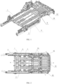
FIG. 1 is a schematic diagram showing an overall structure of a mid and rear floor structure according to embodiments of the present disclosure; -
FIG. 2 is a structure diagram of a bottom beam frame of the mid and rear floor of a mid and rear floor structure according to embodiments of the present disclosure; -
FIG. 3 is a schematic diagram of distribution of battery pack fix points inFIG. 2 ; -
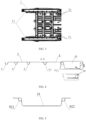
FIG. 4 is a diagram of a cross-section along the A-A line inFIG. 2 ; -
FIG. 5 is a diagram of a cross-section along the C-C line inFIG. 2 ; -
FIG. 6 a schematic diagram of a deformation structure of a seat pit according to embodiments of the present disclosure; -
FIG. 7 is a schematic diagram of a side impact force transmission direction of a mid and rear floor structure according to embodiments of the present disclosure; -
FIG. 8 is a diagram of a cross-section along the B-B line inFIG. 7 ; -
FIG. 9 is an exploded schematic diagram of connectors between a sill beam and a mid floor crossbeam according to embodiments of the present disclosure. - In order to make the purpose, technical solutions and advantages of the embodiments of the present disclosure clearer, the technical solutions in the embodiments of the present disclosure will be clearly and completely described below with reference to the accompanying drawings in the embodiments of the present disclosure. The described embodiments are part of the embodiments of the present disclosure, not all of them. The components of the present disclosed embodiment, typically described and shown in the accompanying drawings, can be arranged and designed in various different configurations.
- Accordingly, the following detailed description of the embodiments of the present disclosure provided in the accompanying drawings is not intended to the claimed scope of the present disclosure, but merely represents selected embodiments of the present disclosure. Based on the embodiments in the present disclosure, all other embodiments obtained by persons of ordinary skill in the art without creative efforts fall within the protection scope of the present disclosure.
- It should be noted that like numerals and letters denote similar items in the following drawings, therefore, once an item is defined in one drawing, it does not require further definition and explanation in subsequent drawings.
- In the description of the present disclosure, it should be noted that the orientations or positional relationships indicated by the terms "center", "upper", "lower", "left", "right", "vertical", "horizontal", "inner", "outer", etc. are based on the orientation or positional relationship shown in the drawings, or the orientation or positional relationship that the product is usually placed in use, and are only for the convenience of describing the present disclosure and simplifying the description, rather than indicating or implying that the referred device or element must have a specific orientation, be constructed and operated in a specific orientation. Therefore, it should not be construed as limiting the present disclosure.
- It should be noted that the terms "first" and "second" are only used for descriptive purposes, and cannot be understood as indicating or implying relative importance or implicitly indicating the quantity of indicated technical features. Thus, a feature defined as "first" and "second" may explicitly or implicitly include one or more of these features. In the description of the present disclosure, "plurality" means two or more, unless otherwise specifically defined.
- Furthermore, the terms "horizontal", "vertical" and the like do not imply that a component is absolutely level or overhanging, but may be slightly inclined. For example, "horizontal" only means that its direction is more horizontal than "vertical", and it does not mean that the structure must be completely horizontal, but can be slightly inclined.
- For pure electric vehicle, a battery is generally arranged under a front mid floor, and the battery is between a battery pack installation crossbeam and a floor. And in order to meet the requirements of cruising range, it is necessary to arrange as many power batteries as possible. In order to ensure the stiffness and strength of the battery pack installation point, the size of the cavity formed by the battery pack installation crossbeam and the floor needs to be as large as possible. Therefore, the floor of the electric vehicle needs to be arranged on the upper side, and the downward movement of the floor is severely restricted.
- The battery pack installation crossbeam and the floor are both supported by the sill, so there is a certain drop between the battery pack installation crossbeam and the sill, and the overlap between the battery pack installation crossbeam and the sill is low, making it difficult to achieve the safety goal of collision stars. In addition, the force transmission path of front impact will basically pass the force through a middle longitudinal beam and sill beams. Generally, the battery pack installation crossbeam and the mid floor crossbeam in this area cannot be used universally.
- In addition, for the rear floor area of the vehicle body, crossbeams are generally arranged up and down to serve as storage space, etc. However, current vehicles may require more seats to meet the needs of more passengers to travel together. Therefore, there is also an urgent need for a flexible vehicle body structure that can increase the number of seats.
- In an embodiment, as shown in
FIG. 7 and FIG. 8 , this embodiment provides a mid and rear floor structure, including a mid floor frame structure and abattery pack 7. The mid floor frame structure includes a crossbeam assembly (such as amid floor crossbeam 3, amid floor crossbeam 4, and amid floor crossbeam 5 shown inFIG. 7 ) and a longitudinal beam assembly (such as afirst sill beam 1 and asecond sill beam 2 shown inFIG. 7 ). Thebattery pack 7 is installed below the crossbeam assembly, and both the crossbeam assembly andbattery pack 7 are supported by the longitudinal beam assembly. In the present disclosure, the battery pack is installed below the crossbeam assembly and supported by the longitudinal beam assembly, such that the vehicle body floor can be set as a flat floor, and the structural strength of the battery pack can be used to enhance the stiffness of the vehicle. - In another embodiment, as shown in
FIG. 1 ,FIG. 7 and FIG. 8 , this embodiment provides a mid and rear floor structure, including amid floor 8, arear floor 9, aseat pit 10, a mid floor frame structure and abattery pack 7. The mid floor frame structure includes a crossbeam assembly and a longitudinal beam assembly. Thebattery pack 7 is installed below the crossbeam assembly. Themid floor 8 is installed above the crossbeam assembly. Themid floor 8, therear floor 9, and theseat pit 10 are sequentially connected. The crossbeam assembly, thebattery pack 7, themid floor 8, therear floor 9, and theseat pit 10 are all supported by the longitudinal beam assembly. - The
mid floor 8 and therear floor 9 are used for installing second-row seats and third-row seats; and theseat pit 10 is used for installing fourth-row seats. - In some embodiments, an upper surface of the
mid floor 8 is laid with seat long slide rails. The laying of long seat slide rails can achieve common rails of the second-row seats and the third-row seats sliding together, and the structure is flexible. - In order to meet the requirement of more passengers traveling together, the present disclosure provides a
seat pit 10 at the rear of the vehicle body, which can be used for folding and storing the fourth-row seats, which can be used for sitting when the fourth-row seats are set in theseat pit 10, or for providing storage space when the fourth-row seats are folded in the seat pit, or for storing goods in the seat pit when the fourth-row seats are not set to provide greater storage space. The floor of the vehicle body adopts the design structure of themid floor 8, which can be laid with long seat slide rails to achieve common rails of the second-row seats and the third-row seats sliding together, and realize large seating space and large storage space as a whole, which is flexible and variable. In addition, thebattery pack 7 is installed below the crossbeam assembly and supported by the longitudinal beam assembly, which not only allows the floor of the vehicle body to be set as themid floor 8, but also enhances the stiffness of the entire vehicle by utilizing the structural strength of thebattery pack 7. - In some embodiments, as shown in
FIG. 2 andFIG. 4 , the longitudinal beam assembly includes afirst sill beam 1 and asecond sill beam 2, and the crossbeam assembly includes a firstmid floor crossbeam 3, a secondmid floor crossbeam 4 and a thirdmid floor crossbeam 5, where both ends of the firstmid floor crossbeam 3, both ends of the secondmid floor crossbeam 4, and both ends of the thirdmid floor crossbeam 5 are respectively connected to thefirst sill beam 1 and the secondmid floor crossbeam 2 through mid floor crossbeam connection brackets 6 (as shown inFIG. 8 ). - In this embodiment, the first
mid floor crossbeam 3, the secondmid floor crossbeam 4 and the thirdmid floor crossbeam 5 are arranged parallel to each other, thefirst sill beam 1 and thesecond sill beam 2 are arranged parallel to each other, and thefirst sill beam 1 and thesecond sill beam 2 are respectively on both sides of the firstmid floor crossbeam 3, both sides of the secondmid floor crossbeam 4 and both sides of the thirdmid floor crossbeam 5. - A
mid floor 8 can be installed above the firstmid floor crossbeam 3, the secondmid floor crossbeam 4 and the thirdmid floor crossbeam 5, so as to facilitate the movement of the seats. - In some embodiments, a
battery pack 7 is installed below the firstmid floor crossbeam 3, the secondmid floor crossbeam 4 and the thirdmid floor crossbeam 5, and two ends of thebattery pack 7 are respectively connected to thefirst sill beam 1 and thesecond sill beam 2. - As for the installation and fixation of the
battery pack 7, as shown inFIG. 3 , in this embodiment, thefirst sill beam 1 and thesecond sill beam 2 are provided with longitudinal beam battery pack fix points 71, thebattery pack 7 can be fixed on the longitudinal beam battery pack fix points 71. In another embodiment, two columns of total six crossbeam battery pack fix points 72 are evenly arranged on the firstmid floor crossbeam 3, the secondmid floor crossbeam 4, and the thirdmid floor crossbeam 5 , that is, two crossbeam battery pack fix points 72 are arranged on each crossbeam, configured to fix thebattery pack 7 together with the longitudinal beam battery pack fix points 71 to achieve uniform fixing of the battery pack in different regions, such that the battery and the vehicle body are fixed to form an integrated body, and the stability is greatly improved. As shown inFIG. 2 andFIG. 7 , arrows inFIG.2 indicate the direction and path of the front impact force transmission, and arrows inFIG. 7 indicate the direction and path of the side impact force transmission. In this embodiment, for the front impact force transmission of the vehicle body, only two longitudinal sill beams are provided to carry the front impact force transmission, and other longitudinal beams are not provided, such that the three mid floor crossbeams (the firstmid floor crossbeam 3, the secondmid floor crossbeam 4, and the third mid floor crossbeam 5) have no specification limitations by other longitudinal beams, achieving universalization. In addition, these three mid floor crossbeams also take battery installation space into account, thebattery pack 7 is installed below each mid floor crossbeam, and these three mid floor crossbeams are connected to the sill beams on both sides. When the vehicle body is subjected to side impact force, not only the mid floor crossbeam realizes side impact force transmission, but also achieves certain support through the structure of thebattery pack 7. The structural strength of thebattery pack 7 is used to enhance the stiffness of the vehicle, effectively protecting the internal passengers and the battery in the collision. - In addition, as shown in
FIG. 2 andFIG. 4 , the bottom of therear floor 9 is provided with two rear floor crossbeams 91 (for example, therear floor crossbeam 911 and therear floor crossbeam 912 inFIG. 4 ) distributed transversely (for example, along the B-B direction inFIG. 7 ). And as shown inFIG. 2 , the bottom ofrear floor 9 is provided with rear floor longitudinal beams 92 (such as rear floorlongitudinal beam 921 and rear floorlongitudinal beam 922 inFIG. 5 ) on both sides ofrear floor 9 distributed longitudinally (such as A-A direction inFIG. 2 ), where the rear floorlongitudinal beam 921 is a structure in which thefirst sill beam 1 extends towards therear floor 9 to the rear, and the rear floorlongitudinal beam 922 is a structure in which thesecond sill beam 2 extends towards therear floor 9 to the rear; the rear floorlongitudinal beam 921 and the rear floor longitudinal beam 922 (i.e., thefirst sill beam 1 and the second sill beam 2) are configured to support therear floor 9 andseat pit 10. Therear floor crossbeam 911 and therear floor crossbeam 912 are respectively located at two ends of therear floor 9 along the A-A direction, and therear floor crossbeam 912 at the rear of therear floor 9 also supports theseat pit 10 at the same time. Therear floor crossbeam 911 and therear floor crossbeam 912 are both at the same level as the firstmid floor crossbeam 3, the secondmid floor crossbeam 4, and the thirdmid floor crossbeam 5, such that themid floor 8 is flush with therear floor 9. - The
seat pit 10 can be designed to be deeper to have more storage space, allowing for more storage space and further achieving the upper part to be flat after flipping the seats into the pit. The rear crashworthiness is greatly improved, and the rear NVH vibration and noise suppression can further be achieved. - As shown in
FIG. 6 , for different requirements, such as the requirement for overall flat floor, elements of the seat pit can be directly removed, and aflat steel plate 93 can be added to the upper part of the seat pit, which can meet a fast switching of vehicle models with different needs, such as fast switching between models with three rows of seats and models with four rows of seats. - In some embodiments, as shown in
FIG. 8 andFIG. 9 , each of thefirst sill beam 1 and thesecond sill beam 2 includes a multi-cavity structure, which can be an aluminium structure in this embodiment. Each of thefirst sill beam 1 and thesecond sill beam 2 includes acrossbeam supporter 11 and abattery supporter 12 that are interconnected. Thecrossbeam supporter 11 is above thebattery supporter 12. A cross-section of thecrossbeam supporter 11 is a hollow quadrilateral shape, a cross-section of thebattery supporter 12 is a porous grid shape, one side of thecrossbeam supporter 11 is connected with the mid floorcrossbeam connection brackets 6, and one side of thebattery supporter 12 is connected with thebattery pack 7. - In this embodiment, each of the
first sill beam 1 and thesecond sill beam 2 includes acrossbeam supporter 11 and abattery supporter 12. The cross-section of thecrossbeam supporter 11 is a hollow quadrilateral, and the cross-section of thebattery supporter 12 is a porous grid shape. As shown inFIG. 7 , the arrow in the figure shows the direction and path of side impact force transmission. When the vehicle body is subjected to a large side impact force, thecrossbeam supporter 11 of thesecond sill beam 2 will first collapse, to transmit the side impact force to each mid floor crossbeam, reducing the force onbattery pack 7; thebattery supporter 12 is relatively stable, which can provide a certain degree of resistance to side impact through thebattery pack 7, and can collapse and absorb energy when subjected to excessive side impact force, protecting thebattery pack 7. - In some embodiments, as shown in
FIG. 9 , thebattery supporter 12 includes a first-layer supporter 121, a second-layer supporter 122 and abottom connector 123 that are connected in sequence, and a cross section of each of the first-layer supporter 121, the second-layer supporter 122 and thebottom connector 123 includes one or more polygons. - In this embodiment, a cross section of the first-
layer supporter 121 includes two interconnected polygons, a cross section of the second-layer supporter 122 includes three sequentially connected polygons, and a cross section of thebottom connector 123 includes two polygons. - In some embodiments, as shown in
FIG. 9 , the mid floorcrossbeam connection bracket 6 includes a first horn shapedconnection plate 601, a second horn shaped connection plate602 and abottom fix plate 603. Thebottom fix plate 603 is fixedly connected to a bottom of the first horn shapedconnection plate 601 and a bottom of the second horn shapedconnection plate 602 to form a U-shaped structure. A top of the first horn shapedconnection plate 601 and a top the second horn shapedconnection plate 602 are configured to connect the firstmid floor crossbeam 3, the secondmid floor crossbeam 4, or the thirdmid floor crossbeam 5. A side of the first horn shapedconnection plate 601 and a side of the second horn shapedconnection plate 602 are configured to connect thefirst sill beam 1 or thesecond sill beam 2. - The top of each of the first horn shaped
connection plate 601 and the second horn shapedconnection plate 602 is provided with afirst connection sheet 604, and both sides of a top of each of the firstmid floor crossbeam 3, the secondmid floor crossbeam 4 and the thirdmid floor crossbeam 5 are correspondingly provided with asecond connection sheet 501; the firstmid floor crossbeam 3, the secondmid floor crossbeam 4 or the thirdmid floor crossbeam 5 is between the first horn shapedconnection plate 601 and the second horn shapedconnection plate 602; thesecond connection sheet 501 is connected with thefirst connection sheet 604. - The bottom of a side of each of the first horn shaped
connection plate 601 and the second horn shapedconnection plate 602 is connected with athird connection sheet 605, thethird connection sheet 605 is configured to connect thefirst sill beam 1 or thesecond sill beam 2. - Compared with directly connecting the sill beam to the crossbeam, the mid floor
crossbeam connection bracket 6 with horn shaped can realize the oblique transmission of the side impact force, and when a large side impact force is received, the crossbeam can be bent upward to a certain extent, avoiding damage to the battery. Moreover, the horn-shaped mid floorcrossbeam connection bracket 6 can better cooperate with thecrossbeam supporter 11 in the multi-cavity structure to achieve a collapse/shrink effect, and can further make the connection between the sill beam and the crossbeam more stable. - In this embodiment, the
first sill beam 1 and thesecond sill beam 2 are connected to thebattery pack 7 through bolts, and thebattery pack 7 and the vehicle body are tightly connected through bolts, and the structural strength of thebattery pack 7 is used to enhance the stiffness of the vehicle, effectively protecting the internal passengers and the battery in a collision. - The above provides a detailed description of some embodiments of the present disclosure. It should be understood that those skilled in the art can make many modifications and changes based on the concept of the present disclosure without creative efforts. Therefore, all technical solutions obtained by those skilled in the art through logical analysis, reasoning or limited experiments according to the concept of the present disclosure shall be within the protection scope determined by the claims.
Claims (16)
- A mid and rear floor structure, comprising a mid floor frame structure and a battery pack (7), wherein the mid floor frame structure comprises a crossbeam assembly and a longitudinal beam assembly, the battery pack (7) is installed below the crossbeam assembly, and the crossbeam assembly and the battery pack (7) are supported by the longitudinal beam assembly.
- The mid and rear floor structure according to claim 1, further comprising a mid floor (8), a rear floor (9), and a seat pit (10), wherein the mid floor (8) is installed above the crossbeam assembly; wherein the mid floor (8), the rear floor (9) and the seat pit (10) are connected in sequence; and wherein the crossbeam assembly, the battery pack (7), the mid floor (8), the rear floor (9) and the seat pit (10) are all supported by the longitudinal beam assembly.
- The mid and rear floor structure according to claim 1 or 2, wherein the longitudinal beam assembly comprises a first sill beam (1) and a second sill beam (2); the crossbeam assembly comprises a first mid floor crossbeam (3), a second mid floor crossbeam (4) and a third mid floor crossbeam (5); and both ends of the first mid floor crossbeam (3), both ends of the second mid floor crossbeam (4) and both ends of the third mid floor crossbeam (5) are respectively connected to the first sill beam (1) and the second sill beam (2) through mid floor crossbeam connection brackets (6).
- The mid and rear floor structure according to claim 3, wherein the battery pack (7) is installed below the first mid floor crossbeam (3), the second mid floor crossbeam (4) and the third mid floor crossbeam (5); and two ends of the battery pack (7) are respectively connected to the first sill beam (1) and the second sill beam (2).
- The mid and rear floor structure according to claim 3, wherein each of the first sill beam (1) and the second sill beam (2) is provided with longitudinal beam battery pack fix points (71), and the battery pack (7) is fixed on the longitudinal beam battery pack fix points (71).
- The mid and rear floor structure according to claim 5, wherein the first mid floor crossbeam (3), the second mid floor crossbeam (4) and the third mid floor crossbeam (5) are all provided with crossbeam battery pack fix points (72), and the battery pack (7) is fixed on the longitudinal beam battery pack fix points (71) and the crossbeam battery pack fix points (72).
- The mid and rear floor structure according to claim 3, wherein each of the first sill beam (1) and the second sill beam (2) comprises a multi-cavity structure.
- The mid and rear floor structure according to any one of claims 3 to 6, wherein the first sill beam (1) and the second sill beam (2) each comprises a crossbeam supporter (11) and a battery supporter (12) connected with each other; the crossbeam supporter (11) is above the battery supporter (12), a cross-section of the crossbeam supporter (11) is a hollow quadrilateral, a cross-section of the battery supporter (12) is a porous grid shape; and one side of the crossbeam supporter (11) is connected with the mid floor crossbeam connection brackets (6), and one side of the battery supporter (12) is connected with the battery pack (7).
- The mid and rear floor structure according to claim 8, wherein the battery supporter (12) comprises a first-layer supporter (121), a second-layer supporter (122) and a bottom connector (123) that are connected in sequence, and a cross section of each of the first-layer supporter (121), the second-layer supporter (122) and the bottom connector (123) comprises one or more polygons.
- The mid and rear floor structure according to claim 9, wherein the cross-section of the first-layer supporter (121) comprises two interconnected polygons, the cross-section of the second-layer supporter (122) comprises three sequentially connected polygons, and the cross-section of the bottom connector (123) comprises two polygons.
- The mid and rear floor structure according to claim 3, wherein each of the mid floor crossbeam connection brackets (6) comprises a first horn shaped connection plate (601), a second horn shaped connection plate (602) and a bottom fix plate (603); and the bottom fix plate (603) is fixedly connected to bottoms of the first horn shaped connection plate (601) and the second horn shaped connection plate (602) respectively to form a U-shaped structure; a top of each of the first horn shaped connection plate (601) and the second horn shaped connection plate (601) is configured to connect the first mid floor crossbeam (3), the second mid floor crossbeam (4) or the third mid floor crossbeam (5); and a side of each of the first horn shaped connection plate (601) and the second horn shaped connection plate (602) is configured to connect the first sill beam (1) or the second sill beam (2).
- The mid and rear floor structure according to claim 11, wherein, the top of each of the first horn shaped connection plate (601) and the second horn shaped connection plate(602) is provided with a first connection sheet (604); and both sides of a top of each of the first mid floor crossbeam (3), the second mid floor crossbeam (4) and the third mid floor crossbeam (5) are correspondingly provided with a second connection sheet (501); the first mid floor crossbeam (3), the second mid floor crossbeam (4) or the third mid floor crossbeam (5) is between the first horn shaped connection plate (601) and the second horn shaped connection plate (602); and the second connection sheet (501) is connected with the first connection sheet (604); and
a bottom of a side of each of the first horn shaped connection plate (601) and the second horn shaped connection plate (602) is connected with a third connection sheet (605), the third connection sheet (605) is configured to connect the first sill beam (1) or the second sill beam (2). - The mid and rear floor structure according to claim 3, wherein the first sill beam (1) and the second sill beam (2) are connected to the battery pack (7) by bolts.
- The mid and rear floor structure according to claim 3, wherein a top of each of the first mid floor crossbeam (3), the second mid floor crossbeam (4) and the third mid floor crossbeam (5) is connected to the mid floor (8).
- The mid and rear floor structure according to any one of claims 2-14, wherein the mid floor (8) and the rear floor (9) are configured to install second-row seats and third-row seats; and the seat pit (10) is configured to install fourth-row seats.
- The mid and rear floor structure according to any one of claims 2-14, wherein upper surfaces of the mid floor (8) and the rear floor (9) are laid with seat long slide rails.
Applications Claiming Priority (4)
| Application Number | Priority Date | Filing Date | Title |
|---|---|---|---|
| CN202111209385.9A CN113734297A (en) | 2021-10-18 | 2021-10-18 | Middle and rear floor board structure |
| CN202122503049.7U CN216185521U (en) | 2021-10-18 | 2021-10-18 | Middle and rear floor board structure |
| CN202122503116.5U CN216185522U (en) | 2021-10-18 | 2021-10-18 | Vehicle-mounted middle battery pack mounting framework |
| PCT/CN2022/123853 WO2023066031A1 (en) | 2021-10-18 | 2022-10-08 | Middle-rear floor framework |
Publications (2)
| Publication Number | Publication Date |
|---|---|
| EP4292907A1 true EP4292907A1 (en) | 2023-12-20 |
| EP4292907A4 EP4292907A4 (en) | 2024-12-11 |
Family
ID=86057926
Family Applications (1)
| Application Number | Title | Priority Date | Filing Date |
|---|---|---|---|
| EP22882641.8A Pending EP4292907A4 (en) | 2021-10-18 | 2022-10-08 | CENTER REAR FLOOR FRAME |
Country Status (2)
| Country | Link |
|---|---|
| EP (1) | EP4292907A4 (en) |
| WO (1) | WO2023066031A1 (en) |
Family Cites Families (15)
| Publication number | Priority date | Publication date | Assignee | Title |
|---|---|---|---|---|
| JP5776509B2 (en) * | 2011-11-24 | 2015-09-09 | トヨタ自動車株式会社 | Battery mounting structure for vehicles |
| JP6106576B2 (en) * | 2013-03-25 | 2017-04-05 | 本田技研工業株式会社 | Vehicle component mounting structure |
| US10112470B2 (en) * | 2017-01-11 | 2018-10-30 | GM Global Technology Operations LLC | Structural enhancements of an electric vehicle |
| JP6930267B2 (en) * | 2017-07-25 | 2021-09-01 | トヨタ自動車株式会社 | Vehicle side structure |
| CN208813328U (en) * | 2018-09-29 | 2019-05-03 | 广州汽车集团股份有限公司 | A lower body frame structure assembly and a vehicle having the same |
| CN209479764U (en) * | 2018-11-30 | 2019-10-11 | 北京长城华冠汽车技术开发有限公司 | A kind of pure electric car car body platform architecture and the new-energy automobile for being equipped with the framework |
| US11091016B2 (en) * | 2019-03-06 | 2021-08-17 | Mazda Motor Corporation | Lower vehicle-body structure of vehicle |
| CN111114652A (en) * | 2020-02-13 | 2020-05-08 | 吴春涛 | Multi-size multi-power platform vehicle body structure and platform vehicle with same |
| DE102020202884A1 (en) * | 2020-03-06 | 2021-09-09 | Psa Automobiles Sa | Substructure for a vehicle |
| JP7447598B2 (en) * | 2020-03-23 | 2024-03-12 | 日産自動車株式会社 | car body floor structure |
| CN212685325U (en) * | 2020-07-20 | 2021-03-12 | 上汽通用五菱汽车股份有限公司 | A body mounting structure for a flip-type seat |
| CN112373570B (en) * | 2020-07-20 | 2024-07-23 | 上汽通用五菱汽车股份有限公司 | Rear lower vehicle body frame structure |
| CN113734297A (en) * | 2021-10-18 | 2021-12-03 | 浙江吉利控股集团有限公司 | Middle and rear floor board structure |
| CN216185522U (en) * | 2021-10-18 | 2022-04-05 | 浙江吉利控股集团有限公司 | Vehicle-mounted middle battery pack mounting framework |
| CN216185521U (en) * | 2021-10-18 | 2022-04-05 | 浙江吉利控股集团有限公司 | Middle and rear floor board structure |
-
2022
- 2022-10-08 WO PCT/CN2022/123853 patent/WO2023066031A1/en not_active Ceased
- 2022-10-08 EP EP22882641.8A patent/EP4292907A4/en active Pending
Also Published As
| Publication number | Publication date |
|---|---|
| EP4292907A4 (en) | 2024-12-11 |
| WO2023066031A1 (en) | 2023-04-27 |
Similar Documents
| Publication | Publication Date | Title |
|---|---|---|
| CN109204496B (en) | Body structure and vehicle | |
| KR102751295B1 (en) | Vehicle floor system | |
| EP3305628B1 (en) | Automobile engine compartment assembly | |
| CN201784713U (en) | Installation structure of vehicle seat | |
| KR102955883B1 (en) | Rear structure of a vehicle body equipped with side members and longitudinal members | |
| US11661114B2 (en) | Vehicle floor structure | |
| CN207141192U (en) | Body structure and vehicle | |
| CN216185522U (en) | Vehicle-mounted middle battery pack mounting framework | |
| CN102975771A (en) | A tubular frame structure for a three-wheeled motor vehicle | |
| EP4292908A1 (en) | Lower vehicle body architecture structure | |
| CN108422844A (en) | Vehicle | |
| CN211568102U (en) | Small-size electric motor car lower body frame | |
| CN113734298A (en) | Vehicle body framework structure under large-scale commercial and passenger dual-purpose pure electric vehicle type | |
| CN212242936U (en) | Battery pack and automobile | |
| WO2025031174A1 (en) | Battery pack case, cell to body and electric vehicle | |
| CN206544545U (en) | Engine compartment frame and vehicle having same | |
| CN221049776U (en) | Shock absorber mounting structure and vehicle | |
| CN115257970A (en) | A battery pack protective structure | |
| CN114715284B (en) | a body frame | |
| CN216185521U (en) | Middle and rear floor board structure | |
| CN213138934U (en) | Novel lightweight lower vehicle body platform of electric vehicle | |
| CN220682484U (en) | Vehicle body frame | |
| CN220682488U (en) | Front cabin frame, vehicle body frame and automobile | |
| CN113734297A (en) | Middle and rear floor board structure | |
| CN223315080U (en) | Body structure, battery pack structure and vehicle |
Legal Events
| Date | Code | Title | Description |
|---|---|---|---|
| STAA | Information on the status of an ep patent application or granted ep patent |
Free format text: STATUS: THE INTERNATIONAL PUBLICATION HAS BEEN MADE |
|
| PUAI | Public reference made under article 153(3) epc to a published international application that has entered the european phase |
Free format text: ORIGINAL CODE: 0009012 |
|
| STAA | Information on the status of an ep patent application or granted ep patent |
Free format text: STATUS: REQUEST FOR EXAMINATION WAS MADE |
|
| 17P | Request for examination filed |
Effective date: 20230915 |
|
| AK | Designated contracting states |
Kind code of ref document: A1 Designated state(s): AL AT BE BG CH CY CZ DE DK EE ES FI FR GB GR HR HU IE IS IT LI LT LU LV MC ME MK MT NL NO PL PT RO RS SE SI SK SM TR |
|
| A4 | Supplementary search report drawn up and despatched |
Effective date: 20241111 |
|
| RIC1 | Information provided on ipc code assigned before grant |
Ipc: B62D 21/15 20060101ALI20241105BHEP Ipc: B60K 1/04 20190101ALI20241105BHEP Ipc: B62D 25/20 20060101AFI20241105BHEP |
|
| DAV | Request for validation of the european patent (deleted) | ||
| DAX | Request for extension of the european patent (deleted) |