EP4292881A2 - Shelf management method and system, pickup area, and stock pickup system - Google Patents
Shelf management method and system, pickup area, and stock pickup system Download PDFInfo
- Publication number
- EP4292881A2 EP4292881A2 EP23207305.6A EP23207305A EP4292881A2 EP 4292881 A2 EP4292881 A2 EP 4292881A2 EP 23207305 A EP23207305 A EP 23207305A EP 4292881 A2 EP4292881 A2 EP 4292881A2
- Authority
- EP
- European Patent Office
- Prior art keywords
- picking
- zone
- passage
- stock
- stock container
- Prior art date
- Legal status (The legal status is an assumption and is not a legal conclusion. Google has not performed a legal analysis and makes no representation as to the accuracy of the status listed.)
- Granted
Links
Images


Classifications
-
- B—PERFORMING OPERATIONS; TRANSPORTING
- B66—HOISTING; LIFTING; HAULING
- B66F—HOISTING, LIFTING, HAULING OR PUSHING, NOT OTHERWISE PROVIDED FOR, e.g. DEVICES WHICH APPLY A LIFTING OR PUSHING FORCE DIRECTLY TO THE SURFACE OF A LOAD
- B66F9/00—Devices for lifting or lowering bulky or heavy goods for loading or unloading purposes
- B66F9/06—Devices for lifting or lowering bulky or heavy goods for loading or unloading purposes movable, with their loads, on wheels or the like, e.g. fork-lift trucks
- B66F9/063—Automatically guided
-
- B—PERFORMING OPERATIONS; TRANSPORTING
- B65—CONVEYING; PACKING; STORING; HANDLING THIN OR FILAMENTARY MATERIAL
- B65G—TRANSPORT OR STORAGE DEVICES, e.g. CONVEYORS FOR LOADING OR TIPPING, SHOP CONVEYOR SYSTEMS OR PNEUMATIC TUBE CONVEYORS
- B65G1/00—Storing articles, individually or in orderly arrangement, in warehouses or magazines
- B65G1/02—Storage devices
- B65G1/04—Storage devices mechanical
- B65G1/137—Storage devices mechanical with arrangements or automatic control means for selecting which articles are to be removed
-
- B—PERFORMING OPERATIONS; TRANSPORTING
- B65—CONVEYING; PACKING; STORING; HANDLING THIN OR FILAMENTARY MATERIAL
- B65G—TRANSPORT OR STORAGE DEVICES, e.g. CONVEYORS FOR LOADING OR TIPPING, SHOP CONVEYOR SYSTEMS OR PNEUMATIC TUBE CONVEYORS
- B65G1/00—Storing articles, individually or in orderly arrangement, in warehouses or magazines
- B65G1/02—Storage devices
- B65G1/04—Storage devices mechanical
- B65G1/137—Storage devices mechanical with arrangements or automatic control means for selecting which articles are to be removed
- B65G1/1373—Storage devices mechanical with arrangements or automatic control means for selecting which articles are to be removed for fulfilling orders in warehouses
- B65G1/1378—Storage devices mechanical with arrangements or automatic control means for selecting which articles are to be removed for fulfilling orders in warehouses the orders being assembled on fixed commissioning areas remote from the storage areas
-
- B—PERFORMING OPERATIONS; TRANSPORTING
- B25—HAND TOOLS; PORTABLE POWER-DRIVEN TOOLS; MANIPULATORS
- B25J—MANIPULATORS; CHAMBERS PROVIDED WITH MANIPULATION DEVICES
- B25J11/00—Manipulators not otherwise provided for
-
- B—PERFORMING OPERATIONS; TRANSPORTING
- B25—HAND TOOLS; PORTABLE POWER-DRIVEN TOOLS; MANIPULATORS
- B25J—MANIPULATORS; CHAMBERS PROVIDED WITH MANIPULATION DEVICES
- B25J9/00—Program-controlled manipulators
- B25J9/16—Program controls
- B25J9/1656—Program controls characterised by programming, planning systems for manipulators
- B25J9/1664—Program controls characterised by programming, planning systems for manipulators characterised by motion, path, trajectory planning
-
- B—PERFORMING OPERATIONS; TRANSPORTING
- B65—CONVEYING; PACKING; STORING; HANDLING THIN OR FILAMENTARY MATERIAL
- B65G—TRANSPORT OR STORAGE DEVICES, e.g. CONVEYORS FOR LOADING OR TIPPING, SHOP CONVEYOR SYSTEMS OR PNEUMATIC TUBE CONVEYORS
- B65G1/00—Storing articles, individually or in orderly arrangement, in warehouses or magazines
- B65G1/02—Storage devices
- B65G1/04—Storage devices mechanical
- B65G1/0485—Check-in, check-out devices
-
- B—PERFORMING OPERATIONS; TRANSPORTING
- B65—CONVEYING; PACKING; STORING; HANDLING THIN OR FILAMENTARY MATERIAL
- B65G—TRANSPORT OR STORAGE DEVICES, e.g. CONVEYORS FOR LOADING OR TIPPING, SHOP CONVEYOR SYSTEMS OR PNEUMATIC TUBE CONVEYORS
- B65G1/00—Storing articles, individually or in orderly arrangement, in warehouses or magazines
- B65G1/02—Storage devices
- B65G1/04—Storage devices mechanical
- B65G1/0492—Storage devices mechanical with cars adapted to travel in storage aisles
-
- G—PHYSICS
- G05—CONTROLLING; REGULATING
- G05D—SYSTEMS FOR CONTROLLING OR REGULATING NON-ELECTRIC VARIABLES
- G05D1/00—Control of position, course, altitude or attitude of land, water, air or space vehicles, e.g. using automatic pilots
- G05D1/02—Control of position or course in two dimensions
- G05D1/021—Control of position or course in two dimensions specially adapted to land vehicles
- G05D1/0287—Control of position or course in two dimensions specially adapted to land vehicles involving a plurality of land vehicles, e.g. fleet or convoy travelling
- G05D1/0291—Fleet control
- G05D1/0297—Fleet control by controlling means in a control room
-
- G—PHYSICS
- G06—COMPUTING OR CALCULATING; COUNTING
- G06Q—INFORMATION AND COMMUNICATION TECHNOLOGY [ICT] SPECIALLY ADAPTED FOR ADMINISTRATIVE, COMMERCIAL, FINANCIAL, MANAGERIAL OR SUPERVISORY PURPOSES; SYSTEMS OR METHODS SPECIALLY ADAPTED FOR ADMINISTRATIVE, COMMERCIAL, FINANCIAL, MANAGERIAL OR SUPERVISORY PURPOSES, NOT OTHERWISE PROVIDED FOR
- G06Q10/00—Administration; Management
- G06Q10/04—Forecasting or optimisation specially adapted for administrative or management purposes, e.g. linear programming or "cutting stock problem"
-
- G—PHYSICS
- G06—COMPUTING OR CALCULATING; COUNTING
- G06Q—INFORMATION AND COMMUNICATION TECHNOLOGY [ICT] SPECIALLY ADAPTED FOR ADMINISTRATIVE, COMMERCIAL, FINANCIAL, MANAGERIAL OR SUPERVISORY PURPOSES; SYSTEMS OR METHODS SPECIALLY ADAPTED FOR ADMINISTRATIVE, COMMERCIAL, FINANCIAL, MANAGERIAL OR SUPERVISORY PURPOSES, NOT OTHERWISE PROVIDED FOR
- G06Q10/00—Administration; Management
- G06Q10/08—Logistics, e.g. warehousing, loading or distribution; Inventory or stock management
-
- G—PHYSICS
- G06—COMPUTING OR CALCULATING; COUNTING
- G06Q—INFORMATION AND COMMUNICATION TECHNOLOGY [ICT] SPECIALLY ADAPTED FOR ADMINISTRATIVE, COMMERCIAL, FINANCIAL, MANAGERIAL OR SUPERVISORY PURPOSES; SYSTEMS OR METHODS SPECIALLY ADAPTED FOR ADMINISTRATIVE, COMMERCIAL, FINANCIAL, MANAGERIAL OR SUPERVISORY PURPOSES, NOT OTHERWISE PROVIDED FOR
- G06Q10/00—Administration; Management
- G06Q10/08—Logistics, e.g. warehousing, loading or distribution; Inventory or stock management
- G06Q10/087—Inventory or stock management, e.g. order filling, procurement or balancing against orders
-
- G—PHYSICS
- G06—COMPUTING OR CALCULATING; COUNTING
- G06Q—INFORMATION AND COMMUNICATION TECHNOLOGY [ICT] SPECIALLY ADAPTED FOR ADMINISTRATIVE, COMMERCIAL, FINANCIAL, MANAGERIAL OR SUPERVISORY PURPOSES; SYSTEMS OR METHODS SPECIALLY ADAPTED FOR ADMINISTRATIVE, COMMERCIAL, FINANCIAL, MANAGERIAL OR SUPERVISORY PURPOSES, NOT OTHERWISE PROVIDED FOR
- G06Q10/00—Administration; Management
- G06Q10/08—Logistics, e.g. warehousing, loading or distribution; Inventory or stock management
- G06Q10/087—Inventory or stock management, e.g. order filling, procurement or balancing against orders
- G06Q10/0874—Inventory fulfillment
- G06Q10/08741—Inventory fulfillment by picking of items from inventory for fulfillment
Definitions
- the present application relates to the field of logistics automation, for example, to a shelf management method and system, a picking zone and a stock picking system.
- robot-based goods-to-person systems have been widely used in the warehousing industry in western developed countries due to their flexibility and low cost.
- shelves are fixed, and operating persons need to walk to designated goods locations to perform operations.
- the robot-based goods-to-person system differs from the traditional operation mode in that a shelf is transported by a mobile robot to a station and queued, and an operating person performs an operation in the station without walking.
- the robot-based goods-to-person mode greatly improves the efficiency of human operations.
- goods can be placed on multiple sides of the mobile shelf.
- goods locations can be provided on the 4 sides of front, back, left and right, while manual operations can be performed only on one side at the same time. Therefore, the shelf needs to be rotated such that the operation side faces the operating person.
- the station can accommodate multiple shelves, but the operating person can only operate one shelf at the same time. Therefore, before the shelf is operated, the robot needs to carry the shelf, queue at the station and wait for the operating person's operation.
- a robot-based goods-to-person system is designed with a fixed queuing zone, uses a fixed side-turning zone to perform a side-turning operation on a shelf, and adopts a method of entering a side-turning zone through an arc.
- the number of robots that can be accommodated in the fixed queuing zone is limited, and the robots that cannot be accommodated stay on a passage and obstruct routes of other robots; a queuing route is relatively fixed, which is likely to cause a route deadlock; the side-turning zone is fixed, which is liable to become a bottleneck of efficiency, and when multiple mobile robots need a side-turning operation, the queuing robots wait for a release of the side-turning zone, so that the mobility becomes worse; and an arc path is used to enter the rotation zone, so that a large margin between the shelves is required, which is not conducive to improving the overall space utilization of a warehouse.
- the present application proposes a shelf management method and system to solve at least one of the foregoing problems, thereby improving the system picking efficiency.
- An aspect of the technical solution of the present application provides a shelf management method, including: estimating whether there is a free space in a station queuing zone of a station; selecting, in response to estimating that there is a free space in the station queuing zone, a shelf from shelves that are allocated to the station and not transported, and controlling a mobile robot to transport the selected shelf; after the mobile robot is butt-jointed with the selected shelf, re-estimating whether there is a free space in any of station queuing zones of all stations needing the selected shelf; in response to estimating that there is a free space in a station queuing zone of all the stations, controlling the mobile robot to transport the selected shelf to the station queuing zone estimated to have a free space, and determining, in a case where the mobile robot transports the selected shelf and arrives at a preset area around the station queuing zone estimated to have a free space, whether there is a free space vacated in the station queuing zone estimated to have a free space; and controlling, in response to
- the method further includes: in response to estimating that there is no free space in any of the station queuing zones of all the stations, controlling the mobile robot to queue and wait in situ.
- the method further includes: in response to there being no free space vacated in the station queuing zone estimated to have a free space, controlling the mobile robot to queue and wait at a position, with a quantity of mobile robots less than a set quantity within a set range around the mobile robot, that does not obstruct routes of other mobile robots, or controlling the mobile robot to transport the selected shelf to another station needing the selected shelf.
- the method further includes: after controlling the mobile robot to enter the station queuing zone estimated to have a free space, determining in real time whether there is a free space vacated ahead of the mobile robot, and in response to determining that there is a free space vacated ahead of the mobile robot, controlling the mobile robot to move toward the free space ahead, or in response to there being no free space vacated ahead of the mobile robot, controlling the mobile robot to queue and wait in situ.
- estimating whether there is a free space in the station queuing zone of the station includes: in response to a number of mobile robots that are currently transporting shelves for a station being smaller than a size of a station queuing zone of the station, determining that the station queuing zone of the station has a free space; or in response to a number of mobile robots that are currently transporting shelves for a station being greater than or equal to a size of a station queuing zone of the station, calculating time for vacating a free space in the station queuing zone of the station, and in response to the time being less than time for a newly allocated mobile robot to arrive at the station queuing zone of the station, determining that the station queuing zone of the station has a free space.
- the method further includes: controlling the mobile robot to perform real-time detection on a surrounding environment of the selected shelf within a traveling route of the mobile robot transporting the selected shelf; and in response to detecting the surrounding environment of the selected shelf meeting a rotation condition, controlling the mobile robot to perform a rotation operation on the selected shelf.
- controlling the mobile robot to perform the rotation operation on the selected shelf includes: in response to detecting the surrounding environment of the selected shelf meeting the rotation condition, controlling the mobile robot to rotate the selected shelf in at least one of following three positions: performing rotation in a transporting route, performing rotation in a rotation zone of the station corresponding to the station queuing zone estimated to have a free space, or performing rotation in situ at an operation position of the station queuing zone estimated to have a free space.
- controlling the mobile robot to perform real-time detection on the surrounding environment of the selected shelf within the traveling route of the mobile robot transporting the selected shelf includes: within the traveling route of the mobile robot transporting the selected shelf, controlling the mobile robot to detect whether a cell within a preset range around a route point ahead is occupied, and in response to the cell within the preset range around the route point ahead being applied for successfully, using the route point ahead as a rotation point; and in a case where the mobile robot arrives at the set rotation point, occupying the cell within the preset range around the route point ahead as the rotation zone, and in response to the cell within the preset range around the route point ahead being not occupied successfully, controlling the mobile robot to continue walking.
- controlling the mobile robot to perform the rotation operation on the selected shelf includes: before the mobile robot arrives at the operation position of the station queuing zone estimated to have a free space, if the mobile robot does not rotate the selected shelf in the traveling route for transporting the selected shelf, controlling the mobile robot to enter the rotation zone of the station corresponding to the station queuing zone estimated to have a free space to rotate the selected shelf.
- the method further includes: in a case where the selected shelf that has been rotated still needs to be rotated, determining whether a cell within a preset range around the mobile robot in-situ being possible to be occupied, and in response to the cell within the preset range around the mobile robot in-situ being possible to be occupied, occupying the corresponding cell as the rotation zone, and in response to the cell within the preset range around the mobile robot in-situ being not possible to be occupied, controlling the mobile robot to enter the station queuing zone estimated to have a free space again and continue to queue and enter the rotation zone of the corresponding station.
- a layout mode of the station queuing zone includes one of: a dual-station symmetrical layout mode, a parallel layout mode, or a mode of queuing with no specific rotation zone.
- the station queuing zone in a case where the layout mode of the station queuing zone includes the dual-station symmetrical layout mode, includes two rotation zones and two queuing passages around the two rotation zones respectively, the two queuing passages being partially overlapped to form a passage area between the two rotation zones, each queuing passage being provided with an entrance position, an operation position, a plurality of rotation zone entry positions, a plurality of queuing return positions, and an exit position, wherein the operation position is a position where the mobile robot transporting the shelf waits for the worker's operation; the rotation zone entry position is a position allowing the mobile robot to enter the rotation zone from the queuing passage; the queuing return position is a position allowing the mobile robot to enter the queuing passage from the rotation zone; the entrance position is set in the passage area, the two queuing passages sharing one entrance position; and the rotation zone entry positions, the queuing return positions and the exit positions on the two queuing passages are symmetrically arranged on two sides of
- the station queuing zone in a case where the layout mode of the station queuing zone includes the parallel layout mode, the station queuing zone includes two rotation zones and two queuing passages around the two rotation zones respectively, each queuing passage being provided with an entrance position, an operation position, a plurality of rotation zone entry positions, a plurality of queuing return positions, and an exit position, the two queuing passages being arranged in parallel, wherein the operation position is a position where the mobile robot transporting the shelf waits for the worker's operation; the rotation zone entry position is a position allowing the mobile robot to enter the rotation zone from the queuing passage; and the queuing return position is a position allowing the mobile robot to enter the queuing passage from the rotation zone.
- the station queuing zone in a case where the layout mode of the station queuing zone includes a mode of queuing with no specific rotation zone, the station queuing zone includes a queuing passage, and the queuing passage is used as a rotation zone, the queuing passage being provided with an operation position, an exit position, and a plurality of entrance positions, the plurality of entrance positions being located between the operation position and the exit position.
- a plurality of directions are set for the exit position, and in a case where the mobile robot needs to perform shelf rotation again after the operation is completed, the mobile robot is allowed to enter the station queuing zone again from the exit position, or leave the station queuing zone from the exit position and return to the station queuing zone via an external route.
- the station queuing zone in a case where a layout mode of the station queuing zone includes a multi-operation point layout mode, includes a plurality of operation positions, the plurality of operation positions being arranged in a line, and each operation position being used as an entrance position and an exit position, and the operation position being a position where the mobile robot transporting the shelf waits for the worker's operation.
- the present application further provides a picking zone, by means of which the queuing and waiting time of a transfer robot in the picking zone is reduced to improve the picking efficiency.
- the present application further provides a stock picking system, by means of which the queuing and waiting time of a transfer robot is reduced to improve the picking efficiency.
- the present invention adopts the following technical solution.
- the two picking points are arranged adjacent to each other.
- the picking work zone is provided with two put walls opposite to each other, each put wall accommodating a plurality of order containers, and the two picking points are located in an extension space formed by the two put walls.
- the two picking points are directly opposite and spaced apart.
- one picking passage of the two picking passages provides a traveling route in a clockwise direction, and the other picking passage provides a traveling route in a counterclockwise direction.
- each picking passage has an entrance grid forming an entrance of the picking passage and an exit grid forming an exit of the picking passage, and a traveling width of the entrance grid and the exit grid is larger than a maximum outer diameter of a stock container.
- each picking passage includes an entrance passage and an exit passage forming two lateral sides of the U shape; the exit passage is located on a side of the picking passage adjacent to another picking station; and the adjacent two picking stations share the one exit passage.
- the two-dimensional grids located upstream of the picking point on the picking passage form an area for the transfer robot to pass and wait.
- a reference mark is provided for positioning by the transfer robot.
- a stock picking system including: a stock container zone configured to store a plurality of stock containers; a transfer robot configured to transport the stock containers; and a picking zone configured for a picking operator to pick target goods from the stock container transported by the transfer robot, wherein: the picking zone includes one or more picking stations, each picking station including two picking passages and two picking points respectively located on the two picking passages, each picking point is configured for the picking operator to pick the target goods; each picking passage is configured to provide a traveling route for the transfer robot to enter the picking station and pass through the picking point on each picking passage in each picking station and leave the picking station.
- the two picking passages are respectively U-shaped and are arranged side by side or in parallel, and the two picking points are respectively located at bottoms of the U shapes of the two picking passages, and a picking work zone for a picking operator to move is formed at an end of the two picking passages away from the stock container zone.
- the two picking passages are arranged adjacent to each other.
- the two picking points are arranged adjacent to each other.
- the picking work zone is provided with two put walls opposite to each other, each put wall accommodating a plurality of order containers, and the two picking points are located between the two put walls.
- the two picking passages in each picking station are respectively U-shaped and are spaced apart from each other; the two picking points are respectively located on lateral sides of the U shapes of the two picking passages and are arranged oppositely, and a picking work zone for a picking operator to move is formed between the two picking passages.
- a picking face of the stock container located in the picking zone is parallel to lateral sides of the U shape of each picking passage.
- one picking passage of the two picking passages provides a traveling route in a clockwise direction, and the other picking passage provides a traveling route in a counterclockwise direction.
- each picking passage has an entrance grid forming an entrance of the picking passage and an exit grid forming an exit of the picking passage, and a traveling width of the entrance grid and the exit grid is larger than a maximum outer diameter of a stock container.
- each picking passage includes an entrance passage and an exit passage forming two lateral sides of the U shape; the exit passage is located on a side of the picking passage adjacent to another picking station; and the adjacent two picking stations share one exit passage.
- the stock container zone and the picking zone are logically provided with two-dimensional grids, wherein one two-dimensional grid in the picking zone corresponds to one of the picking points.
- the two-dimensional grids located upstream of the picking point on the picking passage form an area for the transfer robot to pass and wait.
- a reference mark is provided at a center of at least one of the two-dimensional grids for positioning by the transfer robot.
- Passage an area where a robot can walk when transporting a shelf.
- Station queuing zone an area set near a worker operation position, where a robot transporting a shelf queues and waits for a worker's operation.
- Shelf a square or rectangular shelf that can be transported by a mobile robot.
- a shelf can be divided into multiple layers, and each layer can be provided with locations in four directions (that is, four sides of the shelf).
- a shelf queuing and rotating method including the following steps.
- Step S110 while assigning a transport task, performing queuing scheduling on a transport tool for transporting a shelf, where the queuing scheduling starts when the task is assigned.
- Step S 120 planning a route for the transport tool to transport the shelf according to requirements of an order, and adjusting the traveling route of the transport tool in real time.
- Step S130 performing real-time detection on a surrounding environment where the shelf is located within a traveling route from the allocation to the completion of the transport task.
- Step S140 performing a rotation operation on the shelf when detecting that the surrounding environment where the shelf is located is suitable for rotation.
- the transport tool is a mobile robot.
- performing queuing scheduling on a mobile robot includes: monitoring task time and quantity of a mobile robot in a station queuing zone in real time, and determining whether to allocate a new mobile robot for transporting a shelf to a station according to the task time and quantity of the mobile robot in the station queuing zone. If the task time and quantity of the mobile robot in the station queuing zone are under full load, a new mobile robot is not allocated, that is, allocation of a new transport task is suspended.
- the method includes: performing preferential queue-jump scheduling on a shelf that has a high priority or does not need to be rotated. That is, for a mobile robot that does not need to perform a side-turning operation on a shelf, or a mobile robot with a high priority, a nearest route can be directly planned to insert it into a cell closest to an operation position, while a robot with a low priority waits.
- the method further includes: reducing scheduling on a rotation operation on a shelf. That is, in the case of symmetrical station layout, when allocating of a task, supposing that a face R of a shelf needs to be presented to a worker, to achieve which the shelf needs to be rotated in a station I, but does not need to be rotated in a station II mirrored with respect to the station I, then an order that generates the shelf task can be allocated to the station II, as shown in Fig. 4 .
- the method while assigning a transport task, includes: allocating a corresponding station queuing route layout mode for the transport task according to a task attribute in the transport task.
- the station queuing route layout mode includes a dual-station symmetrical layout mode, a parallel layout mode, a mode of queuing with no specific rotation zone, and a multi-operation point layout mode.
- an area enclosed by cells 1-12 is a rotation zone.
- the cell 8 or 9 is a position where a mobile robot stops and waits for a worker's operation.
- the cell 10 is an exit of a station queuing zone.
- a route for a mobile robot not rotating a shelf is: 1 ⁇ 4 ⁇ 7 ⁇ 9, or 12 ⁇ 5 ⁇ 7 ⁇ 9.
- the mobile robot can carry the shelf from the cell 11, 12, 2 or 3 into the rotation zone and perform rotation of the shelf in the rotation zone, and enter the cell 5, 6, 8 or 9 from the rotation zone, thereby returning to the queuing zone from the rotation zone.
- the specific cells are determined according to a free space in the queue.
- the mobile robot can also perform rotation in the cell 4, which as a second rotation point of the station queuing zone, thereby increasing the efficiency when multiple mobile robots need to perform rotation.
- a system Before rotation in the cell 4, a system locks cells in front of, in the rear of, to the left of, and to the right of the cell 4, to ensure the shelf is rotated safely.
- cells 1- 12 form a queuing route, in which queuing can be clockwise or counterclockwise.
- a rotation zone is enclosed by the cells 1-12.
- a route for a mobile robot not rotating a shelf is: 1 ⁇ 4 ⁇ 6, or 12 ⁇ 5 ⁇ 6.
- the mobile robot can carry the shelf from the cell 2, 11 or 12 into the rotation zone and perform rotation of the shelf in the rotation zone, and enter the cell 3, 5 or 6 from the rotation zone, thereby returning to the queuing zone from the rotation zone.
- the mobile robot stops and waits for a worker's operation.
- the cell 10 is an exit of the station queuing zone.
- the station queuing zone can be arranged adjacent to each other, or it can be arranged several cells apart.
- the mobile robot can also perform rotation in the cell 4, which as a second rotation point of the station queuing zone, thereby increasing the efficiency when multiple mobile robots need to perform rotation.
- a system Before rotation in the cell 4, a system locks cells in front of, in the rear of, to the left of, and to the right of the cell 4, to ensure the shelf is rotated safely.
- an operation position is in a cell 8.
- a cell 10 is an exit of a station queuing zone. Any of cells 1- 8 can be used as a shelf rotation position of the station queuing zone.
- the system locks cells in front of, in the rear of, to the left of, and to the right of the cell, and does not allow other mobile robots to enter, to ensure rotation safety.
- the mode of queuing with no specific rotation zone is not limited to the layout of 2 rows and 5 columns, which can be increased or decreased according to needs.
- the design of a station with multiple operation points adopts an in-line type, where a mobile robot can enter and leave each operation point independently. In such an operation position, the mobile robot does not need to queue and wait for another mobile robot in a process of heading to an operation point.
- the number of the operation points is not limited.
- the mobile robot can rotate the shelf at the operation point; and in a route process of the mobile robot heading to the operation point, the mobile robot can apply for a surrounding cell to perform a shelf rotation task.
- Whether to put down the shelf or wait for operation completion by the mobile robot is determined according to shelf operation time. If the shelf operation time exceeds time for the mobile robot to perform the next task, the mobile robot can put down the shelf and further perform the next task. After a shelf operation is completed, the system allocates a mobile robot to take away the shelf.
- a plurality of directions are set for the cell 10 serving as an exit position, so that in the case where shelf rotation needs to be carried out again after the operation is completed, the mobile robot can enter a station queuing zone again from the cell 10 serving as the exit position, and can also leave the station queuing zone from the cell 10 serving as the exit position and return to the station queuing zone via an external route.
- a rotation operation is performed on the shelf in a process from the allocation to the completion of the transport task, that is, performing real-time inspection on a surrounding environment where the shelf is located in a process from the allocation to the completion of the transport task, and performing rotation if the environment where the shelf is located meets a rotation condition.
- planning a route for the transport tool to transport the shelf according to requirements of an order, and adjusting the traveling route of the transport tool in real time includes the following steps.
- Step S210 estimating a free space in a station queuing zone.
- Step S220 if it is estimated that there is a free space in the station queuing zone, that is, if there is a free space or it is estimated that there is a potential free space in the station queuing zone, selecting a shelf from shelves not transported in the station queuing zone and allocating a mobile robot to transport the shelf.
- Step S230 after the mobile robot gets the shelf (getting the shelf means that the mobile robot has docked with the shelf but has not transported the shelf), re-estimating a free space in the station queuing zone, where estimation is performed on all stations that need the shelf, and if it is estimated that there is a free space, starting to transport the shelf, and if it is estimated that there is no free space, queuing and waiting in situ.
- Step S240 when the shelf arrives at the vicinity of the station queuing zone, if the free space in the station queuing zone is not vacated, choosing a position with a low density of mobile robots that does not obstruct routes of other mobile robots to queue and wait, or conveying the shelf to another station that needs the shelf, and if there is a free space vacated in a station queuing zone, entering the station queuing zone.
- Step S250 if it is determined in real time that there is a free space vacated ahead in the station queuing zone, moving toward the station, and if there is no free space vacated ahead, queuing and waiting in situ.
- step S210 estimating a free space in a station queuing zone includes: if the number of mobile robots (including the number of mobile robots within a station queuing zone) that are currently conveying shelves for a station is smaller than the size of the station queuing zone, there must be a vacant space.
- the time for a mobile robot at the tail of the station queuing zone is vacate a free space, the time being a sum of the time for all mobile robots queuing ahead to move a step and the time for a shelf at the head of the queue to stay and be operated, and if the time is less than the time for a newly allocated mobile robot to arrive at the station queuing zone, estimating that there is a potential free space.
- a rotation operation is performed on the shelf.
- a rotation operation There are three ways of performing a rotation operation on the shelf: performing rotation in a transporting route, performing rotation at a rotation point set in the station queuing zone, and performing rotation in situ at an operation point.
- performing real-time detection on a surrounding environment where the shelf is located within a traveling route from the allocation to the completion of the transport task, and if it is detected that the surrounding environment where the shelf is located is suitable for rotation, performing a rotation operation on the shelf includes the following steps.
- Step S310 determining whether the shelf needs to be rotated; if rotation is not needed, directly preferentially planning a route; and if rotation is needed, proceeding to step S320.
- Step S320 during walking of the mobile robot along a route, detecting whether a cell near a route point ahead is occupied, and if the adjacent cell around the route ahead can be applied for at the same time, using the route point ahead as a rotation point.
- Step S330 when the mobile robot arrives at the set rotation point, occupying the surrounding cell; if the occupation is successful, rotating the shelf, and releasing the occupation of the surrounding cell after the shelf rotation is completed; and if the occupation is unsuccessful, continuing to walk.
- Step S340 Before the mobile robot arrives at the station, if the shelf is not rotated on the route, entering a rotation zone set for the station to perform rotation.
- Step S350 if the shelf that has been rotated still needs to be rotated, determining in situ whether a surrounding cell can be occupied, and if the surrounding cell can be occupied, performing rotation in situ, and if the surrounding cell cannot be occupied, entering the station queuing zone again and continuing to queue and entering a set rotation point to rotate the shelf.
- a straightline and arc line tangent route or a polyline route is used in the rotation zone to perform shelf rotation.
- the shelf is parallel to an adjacent shelf in a straightline section.
- the polyline route mode the shelf is always parallel to an adjacent shelf.
- the transport tool is a mobile robot.
- the queuing scheduling unit includes a transport allocation module configured to monitor task time and quantity of a transport tool in a station queuing zone in real time, and determine whether to allocate a new transport tool for transporting the shelf to the station according to the task time and quantity of the transport tool in the station queuing zone.
- a transport allocation module configured to monitor task time and quantity of a transport tool in a station queuing zone in real time, and determine whether to allocate a new transport tool for transporting the shelf to the station according to the task time and quantity of the transport tool in the station queuing zone.
- the queuing scheduling unit includes a queue-jump module configured to perform preferential queue-jump scheduling on a transport tool for a shelf that has a high priority or does not need to be rotated.
- the queuing scheduling unit includes an optimized scheduling module configured to, while assigning a transport task, reduce scheduling on a rotation operation on a shelf.
- the queuing scheduling unit further includes a queuing route layout allocation module configured to allocate a corresponding station queuing route layout mode for the transport task according to a task attribute in the transport task.
- the station queuing route layout mode includes a dual-station symmetrical layout mode, a parallel layout mode, a mode of queuing with no specific rotation zone, and a multi-operation point layout mode.
- a transport tool in a process of heading to an operation point, a transport tool does not need to queue and wait for another transport tool, and in the case where a cell around the transport tool is not occupied, the transport tool can perform a rotation operation on the shelf at the operation point; in a route process of the transport tool heading to an operation point, the mobile robot can apply for a surrounding cell to perform a shelf rotation task; and whether the next operation of the transport tool is to put down the shelf or wait for operation completion is determined according to shelf operation time; if the shelf operation time exceeds time for the transport tool to perform the next task, the transport tool puts down the shelf and further performs the next task, and after a shelf operation is completed, a transport tool is allocated to take away the shelf; and if the shelf operation time does not exceed the time for the transport tool to perform the next task, the transport tool waits for operation completion.
- a plurality of directions are set for an exit position so that in the case where shelf rotation needs to be carried out again after the operation is completed, the transport tool can re-enter a station queuing zone from the exit position, and can also leave the station queuing zone from the exit position and return to the station queuing zone via an external route.
- the rotation operation unit includes a real-time inspection module configured to perform real-time inspection on a surrounding environment where the shelf is located in a process from the allocation to the completion of the transport task, and perform rotation when the environment where the shelf is located meets a rotation condition.
- the route adjustment unit includes: an estimation module configured to estimate a free space in a station queuing zone; a selection module configured to, if it is estimated that there is a free space in the station queuing zone, select a shelf from shelves not transported in the station queuing zone and allocate a transport tool to transport the shelf; an evaluation module configured to, after the transport tool gets the shelf, re-estimate a free space in the station queuing zone, where estimation is performed on all stations that need the shelf, and if it is estimated that there is a free space, start to transport the shelf, and if it is estimated that there is no free space, queue and wait in situ; a first route planning module configured to, when the shelf arrives at the vicinity of the station queuing zone, if the free space in the station queuing zone is not vacated, choose a position with a low density of transport tools that does not obstruct routes of other transport tools to queue and wait, or convey the shelf to another station that needs the shelf, and if there is a
- the estimation module is configured to, if the number of mobile robots that are currently transporting shelves for a station is smaller than the size of a queuing zone of the station, estimate that there is a free space in the station queuing zone, and if the number of mobile robots that are currently transporting shelves for a station is greater than or equal to the size of a queuing zone of the station, calculate the time for a transport tool at the end of the station queuing zone to vacate a free space, and if the time is less than the time for a newly allocated transport tool to arrive at the station queuing zone, estimate that there is a free space.
- the rotation operation unit to perform a rotation operation on the shelf: performing rotation in a transporting route, performing rotation at a rotation point set in the station queuing zone, and performing rotation in situ at an operation point.
- the transport tool During walking of the transport tool along a route, whether a cell near a route point ahead is occupied is detected, and if the adjacent cell around the route ahead can be applied for at the same time, the route point is used as a rotation point; when arriving at the set rotation point, the transport tool occupies the surrounding cell, and if the occupation is successful, the transport tool rotates the shelf, and releases the occupation of the surrounding cell after the shelf rotation is completed, and if the occupation is unsuccessful, the transport tool continues to walk.
- the transport tool Before the transport tool arrives at the station, if the shelf is not rotated on the route, the transport tool enters a rotation zone set for the station to perform rotation; and in the case where the shelf that has been rotated still needs to be rotated, whether a surrounding cell can be occupied is determined in situ, and if the surrounding cell can be occupied, the transport tool performs rotation in situ, and if the surrounding cell cannot be occupied, the transport tool enters the station queuing zone again and continues to queue and enters a set rotation point to rotate the shelf.
- a straightline and arc line tangent route or a polyline route is used in the rotation zone to perform shelf rotation.
- a shelf management system including: a transport tool configured to transport the shelf; the shelf configured to be provided with locations for placing commodities and be transportable by the mobile robot; a shelf zone configured to store the shelf; and a server configured to execute the shelf management method in this technical solution to perform scheduling configuration on the transport tool and the shelf.
- the transport tool is a mobile robot.
- the mobile robot is a wheel-driven trolley and is provided with a jacking mechanism, and has the abilities to walk in a straight line, walk in an arc line, and turn in situ.
- the jacking mechanism and a trolley body move independently to achieve that the trolley body does not move, while the jacking mechanism performs descending and jacking operations; the trolley body does not move, while the jacking mechanism rotates; the trolley body and the jacking mechanism are locked up and rotate at a same speed; and the trolley body and the jacking mechanism rotate at different speeds at the same time.
- the system further includes a station and a station queuing zone.
- the station is a worker operation position; and the station queuing zone is an area set near the worker operation position, where the transport tool transports the shelf, and queues and waits for a worker's operation.
- Logic and/or steps represented in a flow diagram or otherwise described herein, for example, can be regarded as a sequenced list of executable instructions for implementing a logical function, and can be embodied in any computer-readable medium, for use by or in combination with an instruction execution system, apparatus or device (such as a computer-based system, a system including a processor, or other system that can acquire and execute instructions from an instruction execution system, apparatus or device).
- a "computer-readable medium" can be any apparatus that can contain, store, communicate, propagate or transmit a program for use by or in combination with an instruction execution system, apparatus or device.
- the computer-readable medium includes: an electrical connection part (electronic apparatus) with one or more wires, a portable computer disc cartridge (a magnetic apparatus), a random access memory (RAM), a read only memory (ROM), an erasable programmable read only memory (EPROM) or flash memory, an optical fiber, and a portable compact disk read-only memory (CD-ROM).
- the computer-readable medium can even be paper or other suitable medium on which the program can be printed, because, for example, the paper or other medium can be optically scanned, and then subjected to editing, interpretation or other suitable processing to obtain the program electronically and then store it in a computer memory.
- multiple steps or methods can be embodied in software or firmware stored in a memory and executed by a suitable instruction execution system.
- a suitable instruction execution system For example, if they are embodied in hardware, as in another implementation, they can be embodied by any one or a combination of the following techniques known in the art: a discrete logic circuit with a logic gate circuit for implementing a logic function of a data signal, an application specific integrated circuit with an appropriate combinational logic gate circuit, a programmable gate array (PGA), a field programmable gate array (FPGA) etc.
- the term “a” should be understood as “at least one” or “one or more”; that is, in an embodiment, the number of an element may be one, while in other embodiments, the number of the element may be more than one, and the term “a” cannot be understood as a limitation on the number.
- the stock picking system includes a stock container zone 20, a picking zone 10, a common passage 30, and a transfer robot 40.
- the stock container zone 20 is configured to place stock containers 202, and storage containers 50 for storing goods are placed on the stock containers 202, and goods are placed in the storage container 50;
- the picking zone 10 is spaced apart from the stock container zone 20 and is configured for a picking operator to pick order goods and place the picked order goods into the order boxes;
- the transfer robot 40 is configured to transport a stock container 202 in the stock container zone 20 to the picking zone 10, or transport a stock container 202 from which picking is completed back to stock container zone 20;
- the common passage 30 is provided between the stock container zone 20 and the picking zone 10, and is used for high-speed traveling of the transfer robot 40 to achieve movement of the transfer robot 40 between the stock container zone 20 and the picking zone 10.
- a plurality of stock container groups 201 are provided in the stock container zone 20, with a passage for the transfer robot 40 to travel being formed between every two adjacent stock container groups 201.
- the stock container groups 201 in the stock container zone 20 are arranged in rows and columns.
- Each row of stock container group 201 at least includes one stock container group 201, with a transverse passage 204 arranged along a first direction being formed between every two adjacent rows of stock container groups 201; and each column of stock container group 201 at least includes one stock container group 201, with a longitudinal passage 203 arranged along a second direction being formed between every two adjacent columns of stock container groups 201.
- the first direction and the second direction are perpendicular to each other, and a "cross" intersection or a "T" intersection is formed at the junction of the transverse passage 204 and the longitudinal passage 203.
- Fig. 13 is a schematic structural diagram of a stock container 202 provided in an embodiment of the present application.
- the stock container 202 includes a plurality of partition layers 2022 spaced apart longitudinally and four floor-standing support columns 2024, where a variety of goods can be placed directly on each partition layers 2022, and the goods can also be placed within or on an outer surface of the stock container 202 by any suitable means such as hooks or rods in the stock container 202 or on the stock container 202.
- the partition layer 2022 of the stock container 202 may also be provided with a storage container 50.
- the storage container 50 may be separated from the stock container 202, or may be an integrated structure with the stock container 202.
- One or more pieces of goods can be placed in the storage container 50.
- a storage container 50 being provided on the partition 2022 of the stock container 202 is used as an example for description, and goods are placed in the storage container 50. It can be understood that whether goods are directly placed in the stock container 202 or placed in the stock container 202 through the storage container 50 does not influence the work of the stock picking system in this embodiment.
- an open side of the stock container 202 is referred to as a picking face, that is, a face used for picking and placing the storage container 50.
- a picking operator can operate the goods in the storage container 50 on the stock container 202 through the picking face of the stock container 202.
- a stock container 202 with two open sides has two picking faces opposite to each other, and the order goods can be placed in a storage container 50 corresponding to any picking face of the stock container 202; a stock container 202 with one open side, a picking operation only carried out on a storage container 50 corresponding to the picking face; and a four-way opening stock container 202 has four picking faces, and a picking operation can be carried out on a storage container 50 corresponding to any of the four picking faces.
- the lifting mechanism 401 operates to cause the pallet to descend, thereby causing the stock container 202 to fall into contact with the ground, and the pallet continues to descend till coming out of contact with the stock container 202, and the transfer robot 40 moves out of the bottom of the stock container 202 by using the driving mechanism 402 to achieve separation between the stock container 202 and the transfer robot 40.
- the transporting of the stock container 202 may also be submerged type.
- a butt-joint apparatus for butt-jointing the stock container 202 and the transfer robot 40 is provided at the bottom of the stock container 202 or at the top of the transfer robot 40.
- the transfer robot 40 travels along the transverse passage 204 and/or the longitudinal passage 203 in the stock container zone 20, and runs to the bottom of the stock container 202. After the stock container 202 and the transfer robot 40 come into butt-joint connection by the butt-joint apparatus, the stock container 202 is dragged to the target position.
- the transporting of the stock container 202 by the transfer robot 40 may also be traction type.
- the transfer robot 40 is hooked to the stock container 202 through a traction mechanism, and the transfer robot 40 moves to drag the stock container 202 to move.
- the transporting of the stock container 202 by the transfer robot 40 may also be other forms, which are not listed one by one in this embodiment.
- the transfer robot 40 is further provided with a rotating mechanism connected with the pallet, and the rotating mechanism can cause the pallet to rotate, thereby causing the stock container 202 to rotate while keeping the traveling direction of the transfer robot 40 unchanged, to change the orientation of the stock container 202 during transporting. That is, in this embodiment, the rotation movement of the transfer robot 40 can be separated from the rotation movement of the stock container 202.
- the movement of the transfer robot 40 may be forward movement, backward movement, self-rotation for direction changeover, turning, or the like, and the orientation of the stock container 202 may be unchanged during the movement such as forward movement, backward movement and self-rotation for direction changeover of the transfer robot 40.
- the rotating mechanism can operate to cause the pallet to rotate, thereby causing the stock container 202 to rotate.
- the transfer robot 40 also has an autonomous navigation function.
- autonomous navigation being two-dimensional code navigation as an example, the transfer robot 40 further includes a navigation identification component configured to identify a two-dimensional code mark provided on the ground.
- the transfer robot 40 further includes a downward-facing camera. The transfer robot 40 can navigate to travel forward according to two-dimensional code information (may also be other ground mark) captured by the downward-facing camera, and can travel to the underside of the target stock container 202 as prompted by a control system according to a route determined by the control system.
- the transfer robot 40 may also adopt other navigation mode, such as inertial navigation, or simultaneous localization and mapping (SLAM) navigation, or may also adopt a combination of two or more of the aforementioned navigation modes, such as two-dimensional code navigation and inertial navigation, or SLAM navigation and two-dimensional code navigation, or the like.
- other navigation mode such as inertial navigation, or simultaneous localization and mapping (SLAM) navigation
- SLAM simultaneous localization and mapping
- each stock container group 201 two columns of stock containers 202 are provided in each stock container group 201, and a plurality of stock containers 202 are arranged side by side along the second direction in each column of stock containers 202. That is, each stock container 202 faces a same longitudinal passage 203.
- transfer robot 40 When the transfer robot 40 transports any stock container 202 in the stock container group 201, transfer robot 40 can enter a space underneath the stock container 202 through the longitudinal passage 203 that the stock container 202 faces, and after the stock container 202 is jacked up by the transfer robot 40, the stock container 202 is brought into the longitudinal passage 203, so that the stock container 202 is moved out; or when the stock container 202 needs to be moved back to the initial position of the stock container group 201, the transfer robot 40 drives the stock container 202 to move into the initial position through the longitudinal passage 203, to achieve the reset of the stock container 202.
- each stock container group 201 can avoid interference with other stock containers 202 in the stock container group 201 when the transfer robot 40 transports a stock container 202, thereby improving the transport efficiency.
- two rows of stock containers 202 may alternatively be provided in each stock container group 201, and each row of stock containers 202 includes a plurality of stock containers 202, that is, each stock container in the stock container group 201 202 is adjacent to a transverse passage 204, and the transfer robot 40 can move the target stock container 202 out of or into the stock container group 201 through the corresponding transverse passage 204.
- each stock container group 201 can be provided with more than two columns and more than two rows of stock containers 202. In this case, some of the stock containers 202 in the group 201 are surrounded by other stock containers 202 at the periphery.
- another one or more transfer robots 40 need to be dispatched at the same time to move away a stock container 202 on a side of the target stock container 202, and thereafter, the target stock container 202 is transported.
- a stock container group 201 is respectively provided at each of three edges of the stock container zone 20 which are not adjacent to the picking zone 10, where the stock container zone 20 is arranged along the first direction, and the stock container group 201 away from an edge of the stock container zone 20 includes a row of stock containers 202; two columns of stock containers 202 are respectively arranged at two edges along the second direction of the stock container zone 20; and two ends of the row of stock containers 202 are in butt-joint with two ends of the two columns of stock containers 202, so that the stock container zone 20 forms a semi-closed space that is open toward the picking zone 10.
- the common passage 30 is arranged along the first direction and is located between the picking zone 10 and the stock container zone 20.
- the transfer robot 40 enters or exits the stock container zone 20 through the common passage 30, or enters or exits the picking zone 10, or moves between the picking zone 10 and the stock container zone 20. Therefore, the density of the transfer robot 40 in the common passage 30 is greater than the density of the transfer robot 40 in the stock container zone 20 and the picking zone 10. To reduce obstacles to the traveling of the transfer robot 40, no obstacles are provided in the common passage 30.
- the common passage 30 includes four traveling passages arranged along the first direction, and transfer robots 40 in two adjacent traveling passages are allowed to travel in opposite directions to avoid collision during traveling of the transfer robots 40 in the common passage 30, and also ease the traffic in the common passage 30.
- the number of traveling passages in the common passage 30 may be two, or may also be six or more, and in an embodiment, the number of traveling passages in the common passage 30 is even number, and the traveling direction of the transfer robots 40 in two adjacent traveling passages are opposite.
- the picking zone 10 is provided on a side of the stock container zone 20, and the picking zone 10 faces the open side of the stock container zone 20.
- picking is performed manually; that is, a picking operator picks order goods in the stock container 202 conveyed to the picking zone 10.
- an automatic picking mode may alternatively be adopted, that is, a robotic arm is used to pick the order goods in the stock container 202 moved to the picking zone 10.
- manual picking is used as an example to describe the picking work in the picking zone 10.
- the picking zone 10 includes a plurality of picking stations 1 arranged side by side along the first direction, and in each picking station 1, order goods are picked by one picking operator.
- the number of the picking stations 1 in the picking zone 10 can be set autonomously according to needs.
- Fig. 15 is a schematic structural diagram of a picking station and a stock container provided in an embodiment of the present application.
- each picking station 1 is provided with two picking points 122 and two picking passages 121, and the picking passages 121 are arranged in a one-to-one correspondence with the picking points 122, so that each picking passage 121 provides a route for the transfer robot 40 to pass the corresponding picking point 122.
- the two picking points 122 of each picking station 1 can be used by the same picking operator to pick target goods.
- each picking passage 121 enables the transfer robot 40 to enter the corresponding picking point 122 , so that a given picking operator can be responsible for the picking at the two picking points 122, and after the picking operator has finished picking the stock container 202 at one picking point 122, and the transfer robot 40 entering from the picking passage 121 has not yet conveyed a stock container 202 to the picking point 122, the picking operator can perform picking in the stock container 202 waiting for picking at the other picking point 122, thus reducing the idle waiting time of the picking operator, and improving the picking efficiency.
- the picking passage 121 is U-shaped, open toward the stock container zone 20, and both an entrance and an exit of the picking passage 121 face the stock container zone 20.
- the picking passage 121 is formed by planning with a two-dimensional grid arranged in a rectangular array, which is beneficial to improving the regularity of the picking passage 121, and thereby improving the planning consistency and layout compactness of the entire picking zone 10.
- the picking passage 121 is formed by planning with two columns of two-dimensional grid groups arranged side by side in the first direction, and each column of two-dimensional grid group includes a plurality of two-dimensional grids 123 arranged side by side in the second direction.
- a connecting line of centers of one column of two-dimensional grid group along the second direction forms an entrance passage 1211 of the U-shaped passage, and a two-dimensional grid 123 of the entrance passage 1211 in butt-joint with the common passage 30 is an entrance grid 1231;
- a connecting line of centers of the other column of two-dimensional grid group along the second direction is an exit passage 1212 of the U-shaped passage, and a two-dimensional grid 123 of the exit passage 1212 in butt-joint with the common passage 30 is an exit grid 1232;
- a connecting line of centers of the two-dimensional grids 123 at tail ends the two columns of two-dimensional grid groups away from the common passage 30 forms a direction changeover passage 1213 of the U-shaped passage, the direction changeover passage 1213 being arranged in the first direction, and two ends of the direction changeover passage 1213 being respectively connected to the tail ends of the exit passage 1212 and the entrance passage 1211; and when traveling to the junction of the direction changeover passage 1213 and the entrance passage 1211, or the
- each column of two-dimensional grid group includes four two-dimensional grids 123 to improve the space utilization of the picking zone 10 and the space compactness of the stock picking system.
- the two-dimensional grids 123 may be formed by virtual logical division in a controller of the stock picking system, or may be formed by grid marking in an actual site.
- a reference mark for positioning of the transfer robot 40 is provided in the center of at least one two-dimensional grid.
- a reference mark for navigation of the transfer robot 40 is affixed to the center of each two-dimensional grid 123.
- the reference mark is a two-dimensional code
- the transfer robot 40 is provided with a camera for scanning the two-dimensional code. The navigation of the transfer robot 40 by using a two-dimensional code is a conventional technical means in the art, and its principles and specific operations are not described in this embodiment.
- a picking point 122 is provided at the bottom of the U shape of the picking passage 121, and a picking work zone 11 configured for the picking operator to move is provided on a side of the picking passage 121 away from the stock container zone 20.
- the two picking passages 121 of the same picking station 1 are arranged adjacent to each other.
- a two-dimensional grid located at the bottom end and adjacent to the other picking passage 121 forms a picking point 122, so that the two picking points 122 can be arranged side by side and adjacent to each other, to reduce the distance between the two picking points 122.
- the two-dimensional grids forming the two picking points 122 may alternatively be spaced apart.
- the exit passage 1212 of each picking passage 121 is adjacent to another picking passage 121 of the same picking station 1.
- the picking point 122 occupies the two-dimensional grid 123 at the junction of the exit passage 1212 and the direction changeover passage 1213.
- the transfer robot 40 travels to the picking point 122 through the entrance passage 1211 and the direction changeover passage 1213, the stock container 202 transported by the transfer robot 40 is picked at the picking point 122 by the picking operator. After the picking is completed, the transfer robot 40 moves out of the picking station 1 along the exit passage 1212.
- each two-dimensional grid 123 can be occupied by only one transfer robot 40.
- a two-dimensional grid between the entrance grid 1231 of the picking passage 121 and the picking point 122 forms a waiting area for the transfer robot 40 to travel and wait, and each waiting area can accommodate one transfer robot 40 waiting in the waiting area to move to the picking point 122.
- the next waiting transfer robot 40 transporting a stock container 202 moves to the picking point 122 and waits for picking.
- two put walls 112 for placing order boxes are arranged in the picking work zone 11.
- the two put walls 112 are arranged oppositely, and the two picking points 122 are located at an extension side of a space formed by the two put walls 112, and a plurality of order containers for storing order boxes are arranged on each put wall 112.
- This configuration can increase the number of order boxes stored in the picking work zone 11, that is, increase the number of orders that can be handled by the picking operator synchronously.
- a display screen is provided in the picking work zone 11, and the display screen is communicatively connected with the controller of the stock picking system, and is configured to display order information and picking information of the picking that the picking station 1 is responsible for, to facilitate the picking operator picking goods with reference to the order information.
- the order information at least includes the type of the order goods in each pick-up order, the quantity of each type of order goods, a stock container 202 corresponding to each type of order goods, and the position of each type of order goods on the stock container 202.
- the picking information may include a currently picked stock container 202, the type of target goods on the currently picked stock container 202, the position of each type of target goods on the currently picked stock container 202, the picked quantity of each type of target goods on the currently picked stock container 202, the position of one or more order boxes corresponding to each type of target goods on a put wall 112, and the like.
- the picking operator can pick only one order at a time; that is, only after the target goods of an order have been picked, can the picking for the next order begin.
- the picking operator can perform picking operations on multiple orders at the same time.
- Single-order picking and multi-order synchronous picking are both conventional technical means in the art, and are not described in this embodiment.
- a picking face 2021 of the stock container 202 faces the picking zone 10
- the picking face 2021 of the stock container 202 is oriented same as a work face of a picking point 122.
- the work face of the point 122 is a side of the picking point 122 facing the picking working area 11. That is, in the process that the transfer robot 40 carrying the stock container 202 travels to the picking point 122, picking of goods by the picking operator can be achieved without rotating the stock container 202 for direction changeover.
- the stock container 202 has two opposite open sides, and on each partition layer 2022 of the stock container 202, at least one storage container 50 can be arranged side by side in the first direction, and only one storage container 50 is arranged in the second direction; or the stock container 202 has four open sides, but only one storage container 50 is provided on each partition layer 2022 of the stock container 202.
- the length of the stock container 202 in the first direction is L 0
- the width of the stock container 202 in the second direction is W 0
- the width L 2 of the transverse passage 204 is greater than L 0
- the width W 2 of the longitudinal passage 203 is greater than W 0
- the length Li of each two-dimensional grid 123 along the first direction is greater than L 0
- the width W 1 of each two-dimensional grid 123 in the second direction is greater than W 0
- W 1 is slightly larger than W 0
- Li is slightly larger than L 0 .
- the sizes of respective two-dimensional grids 123 are same.
- the stock picking system provided in this embodiment further includes a control system for controlling operations of multiple components in the stock picking system.
- the control system includes an order management center configured to receive orders from and deliver orders to transfer robots and picking stations.
- This embodiment further provides a picking method, which is applied to the above-mentioned stock picking system.
- the picking method provided in this embodiment includes the following steps.
- Step S1010 an order management center receives a pick-up order, analyzes the position of a target stock container 202 corresponding to order goods in the pick-up order in a stock container zone 20, and at the same time plans a target picking station 1 corresponding to the pick-up order.
- Step S1020 the order management center dispatches a transfer robot 40, and plans a first traveling route for the transfer robot 40 according to an initial position of the transfer robot 40 and the position of the target stock container 202.
- Step S1030 the transfer robot 40 travels to the bottom of the target stock container 202 according to the first traveling route.
- Step S1040 a lifting mechanism 401 of the transfer robot 40 operates to cause a pallet to rise and come into contact with the bottom of the stock container 202 until the target stock container 202 comes out of contact with the ground.
- Step S1050 a control system determines a target picking passage 121 that the transfer robot 40 needs to enter according to the congestion of transfer robots 40 in two picking passages 121 in the target picking station 1.
- Step S1060 the control system plans a second traveling route for the transfer robot 40 according to the position of an entrance grid of the target picking passage 121 and the position of the target stock container 202.
- Step S1060 the transfer robot 40 travels to the entrance grid of the target picking passage 121 according to the second traveling route, where during this process, the target stock container 202 does not perform direction changeover movement, and the transfer robot 40 can perform forward movement, backward movement, self-rotation for direction changeover, or the like.
- Step S1070 the transfer robot 40 moves forward along a second direction according to an entrance passage to a tail end of the entrance passage, self-rotates 90 ° and travels along a direction changeover passage 1213 to the picking point 122.
- Step S1080 a picking operator picks target goods on the target stock container 202.
- Step S1090 after the picking is completed, the transfer robot 40 self-rotates 90 ° for direction changeover and travels along an exit passage 1212 to an exit grid 1232 while carrying the stock container 202.
- Step S1100 the control system plans a third traveling route according to the position of the exit grid 1232 and the position of the target stock container 202 in the stock container zone 20, and the transfer robot 40 transports the stock container 202 back to the stock container zone 20 according to the third traveling route.
- Step S1110 the lifting mechanism 401 of the transfer robot 40 operates to cause the pallet to descend until the stock container 202 comes into contact with the ground and the pallet comes out of contact with the bottom of the stock container 202.
- Step S1120 a driving mechanism 402 of the transfer robot 40 operates such that the transfer robot 40 moves out of the bottom of the stock container 202 and becomes separated from the stock container 202.
- This embodiment further provides a warehousing and logistics system, which includes the above-mentioned stock picking system.
- Fig. 16 is a schematic structural diagram of a stock picking system provided in an embodiment of the present application.
- this embodiment provides a stock picking system, which is mainly used to implement "goods-to-person" picking of order goods, and may also achieve conventional warehousing and logistics operations such as goods loading and stock check.
- the stock picking system includes a stock container zone 20, a common passage 30, a picking zone 10, and transfer robots 40.
- the arrangements of the stock container zone 20, the common passage 30, the picking zone 10, and the transfer robots 40 are substantially the same as in Embodiment I, with the only difference in the configuration of the picking passage 121 in the picking station 1. Same structures as in Embodiment I will not be repeated in this embodiment.
- an entrance passage 1211 of each picking passage 121 is arranged adjacent to another picking passage 121, and an exit passage 1212 of each picking passage 121 is arranged adjacent to another picking station 1.
- two adjacent picking passages 1211 share one exit passage 1212.
- two adjacent picking stations 1 may share one put wall 112, and the put wall 112 has two open sides, each for placing order containers.
- one put wall 112 may be provided in a picking work zone 11 of a picking station 1, and the put wall 112 is spaced apart from a picking point 122, and a picking operator is allowed to move between the put wall 112 and the picking point 122.
- Fig. 17 is a schematic structural diagram of a stock picking system provided in an embodiment of the present application.
- this embodiment provides a stock picking system, which is mainly used to implement "goods-to-person" picking of order goods, and may also achieve conventional warehousing and logistics operations such as goods loading and stock check.
- the stock picking system includes a stock container zone 20, a common passage 30, a picking zone 10, and transfer robots 40.
- the arrangements of the stock container zone 20, the common passage 30, the picking zone 10, and the transfer robots 40 are substantially the same as in Embodiment I, with the only difference in the configuration of the stock container 202 in the stock container zone 20 and the configuration of the two-dimensional grid 123. Same structures as in Embodiment I will not be repeated in this embodiment.
- the stock container 202 is open on two sides, where one open side of the stock container 202 faces the picking zone 10, and the other open side faces away from the picking zone 10.
- Each partition layer 2022 of the stock container 202 is provided with two rows of storage containers 50 side by side along the second direction, and each row of storage container 50 includes at least one storage container 50. That is, the stock container 202 has two opposing picking faces 2021, and each picking face 2021 can only be used for taking and placing the storage container 50 on the corresponding open side.
- the stock container 202 does not need direction changeover to implement picking; and if the target goods is placed at a picking face 2021 away from the picking zone 10, during the process of transporting the stock container 202 by the transfer robot 40 to the picking point 122, the stock container 202 needs to be rotated 180 ° such that the picking face 2021 corresponding to the target goods faces the picking work zone 11.
- the length of the stock container 202 in the first direction is L0
- the width of the stock container 202 in the second direction is W 0
- the width L 2 of the transverse passage 204 is greater than L0
- the width W 2 of the longitudinal passage 203 is greater than W 0
- the length Li of each two-dimensional grid 123 in the first direction is greater than L 0
- the width W 1 of each two-dimensional grid 123 in the second direction is greater than W 0
- W 1 is slightly larger than W 0
- Li is slightly larger than L 0 .
- each picking passage 121 is provided with a rotation zone for the stock container 202 to rotate for direction changeover, and as the stock container 202 needs to be rotated for direction changeover before traveling to the picking point 122, the rotation zone is one of corresponding two-dimensional grids 123 forming an entrance passage 1211.
- an entrance grid 1231 of each picking passage 121 forms the above-mentioned rotation zone, to ensure the consistency of subsequent two-dimensional grids 123, reduce the difficulty of planning, and avoid traveling interference between transfer robots 40.
- the above-mentioned rotation zone may also be formed by any one of the two-dimensional grids 123 forming the entrance passage 1211.
- the length L 3 of the two-dimensional grid 123 corresponding to the rotation zone in the first direction is consistent with the length Li of a two-dimensional grid 123 corresponding to a non-rotation zone in the first direction, and the width of the two-dimensional grid 123 corresponding to the rotation zone in the second direction is greater than a maximum outer diameter of the stock container 202, that is, W 3 ⁇ W 0 2 + L 0 2 .
- an exit grid 1232 and an entrance grid 1231 have the same size; that is, the stock container 202 may also be rotated for direction changeover in the exit grid 1232 such that the rotated stock container 202 recovers the original orientation. That is, in this embodiment, the lengths of the two-dimensional grids 123 in the first direction in each picking passage 121 are same, but the widths of the exit grid 1232 and the entrance grid 1231 in the second direction are greater than that of other two-dimension grids 123 in the picking passage 121, so as to provide space for the stock container 202 to rotate for direction changeover, and also to improve the space utilization of the picking zone 10.
- This embodiment further provides a picking method, which can implement double-sided picking of a stock container.
- the picking method provided in this embodiment is as follows.
- Step S2010 an order management center receives a pick-up order, analyzes the position of a target stock container 202 corresponding to order goods in the pick-up order in a stock container zone 20, and at the same time plans a target picking station 1 corresponding to the pick-up order.
- Step S2020 the order management center dispatches a transfer robot 40, and plans a first traveling route for the transfer robot 40 according to an initial position of the transfer robot 40 and the position of the target stock container 202.
- Step S2030 the transfer robot 40 travels to the bottom of the target stock container 202 according to the first traveling route.
- Step S2040 a lifting mechanism 401 of the transfer robot 40 operates to cause a pallet to rise and come into contact with the bottom of the stock container 202 until the stock container 202 comes out of contact with the ground.
- Step S2050 a control system determines a target picking passage 121 that the transfer robot 40 needs to enter according to the congestion of transfer robots 40 in two picking passages 121 in the target picking station 1.
- Step S2060 the control system plans a second traveling route for the transfer robot 40 according to the position of an entrance grid of the target picking passage 121 and the position of the target stock container 202.
- Step S2070 the transfer robot 40 travels to the entrance grid 1231 of the target picking passage 121 according to the second traveling route, where during this process, the target stock container 202 does not perform direction changeover movement, and the transfer robot 40 can perform forward movement, backward movement, self-rotation for direction changeover, or the like.
- Step S2080 the control system determines whether to perform picking on two sides or one side of the target stock container 202 according to order information, and if picking is to be performed on one side of the target stock container 202 and a picking face 2021 faces away from the picking point 122, executes step S2090, and if picking is to be performed on one side of the target stock container 202 and a picking face 2021 faces the picking point 122, executes step S2110.
- Step S2090 the pallet of the transfer robot 40 rotates to cause the target stock container 202 to rotate 180 °, and then execute step S2100.
- Step S2100 the transfer robot 40 moves forward along a second direction according to an entrance passage to a tail end of the entrance passage 1211, self-rotating 90 ° and traveling along a direction changeover passage 1213 to the picking point 122.
- Step S2110 a picking operator picks target goods on the target stock container 202.
- Step S2120 after the picking is completed, the transfer robot 40 self-rotates 90 ° for direction changeover and travels along an exit passage 1212 to an exit grid 1232 while carrying the stock container 202.
- Step S2130 the control system plans a third traveling route according to the position of the exit grid 1232 and the position of the target stock container 202 in the stock container zone 20, and the transfer robot 40 transports the stock container 202 back to the stock container zone 20 according to the third traveling route.
- Step S2140 the lifting mechanism 401 of the transfer robot 40 operates to cause the pallet to descend until the target stock container 202 comes into contact with the ground and the pallet comes out of contact with the bottom of the target stock container 202.
- Step S2150 a driving mechanism 402 of the transfer robot 40 operates such that the transfer robot 40 moves out of the bottom of the stock container 202 and becomes separated from the target stock container 202.
- the stock container 202 may be rotated for direction changeover at the exit grid 1232 such that the orientation of the stock container 202 is restored to the original position, or direction changeover may alternatively be not performed, and in this case, the orientation of the stock container 202 needs to be updated in the control system.
- providing the rotation zone is beneficial to implementing the double-sided picking work of the stock container 202, reducing space occupation of a separate rotation zone, and improving structural compactness and the space utilization of the picking zone.
- This embodiment further provides a warehouse logistics system, which includes the above-mentioned stock picking system.
- Fig. 18 is a schematic structural diagram of a stock picking system provided in an embodiment of the present application.
- this embodiment provides a stock picking system, which is mainly used to implement "goods-to-person" picking of order goods, and may also achieve conventional warehousing and logistics operations such as goods loading and stock check.
- the stock picking system includes a stock container zone 20, a common passage 30, a picking zone 10, and transfer robots 40, where the arrangements of the stock container zone 20, the common passage 30, the picking zone 10, and the transfer robots 40 are substantially same as in Embodiment II, with the only difference in the configuration of the stock container 202 in the stock container zone 20 and the configuration of the two-dimensional grid 123. Same structures as in Embodiment I will not be repeated in this embodiment.
- a picking face 2021 of the stock container 202 faces a longitudinal passage 203 or faces away from the longitudinal passage 203.
- the stock container 202 needs to be rotated such that the picking face 2021 faces the picking work zone 11.
- double-sided picking of the stock container 202 is required, after picking is performed on one side, the stock container 202 needs direction changeover, and then picking is carried out on the other side of the stock container 202.
- the length of the stock container 202 in the first direction is L 0
- the width of the stock container 202 in the second direction is W 0
- the width L 2 of the transverse passage 204 is greater than L 0
- the width W 2 of the longitudinal passage 203 is greater than W 0
- the length L 3 of the two-dimensional grid 123 corresponding to the rotation zone in the first direction is greater than W 0
- its width W 3 in the second direction is greater than W 0 2 + L 0 2 .
- the length Li of a two-dimensional grid 123 except for the rotation zone in each picking passage 121 in the first direction is greater than W 0
- its width W 1 in the second direction is greater than L 0
- W 1 is slightly larger than L 0
- L 1 is slightly larger than W 0 .
- This embodiment further provides a picking method, which is applied to the above-mentioned stock picking system.
- the picking method provided in this embodiment includes the following steps.
- Step S3010 an order management center receives a pick-up order, analyzes the position of a target stock container 202 corresponding to order goods in the pick-up order in a stock container zone 20, and at the same time plans a target picking station 1 corresponding to the pick-up order.
- Step S3020 the order management center dispatches a transfer robot 40, and plans a first traveling route for the transfer robot 40 according to an initial position of the transfer robot 40 and the position of the target stock container 202.
- Step S3030 the transfer robot 40 travels to the bottom of the target stock container 202 according to the first traveling route.
- Step S3040 a lifting mechanism 401 of the transfer robot 40 operates to cause a pallet to rise and come into contact with the bottom of the stock container 202 until the target stock container 202 comes out of contact with the ground.
- Step S3050 a control system determines a target picking passage 121 that the transfer robot 40 needs to enter according to the congestion of transfer robots 40 in two picking passages 121 in the target picking station 1.
- Step S3060 the control system planning a second traveling route for the transfer robot 40 according to the position of an entrance grid of the target picking passage 121 and the position of the target stock container 202.
- Step S3070 the transfer robot 40 travels to the entrance grid 1232 of the target picking passage 121 according to the second traveling route, where during this process, the stock container 202 does not perform direction changeover movement, and the transfer robot 40 can perform forward movement, backward movement, self-rotation for direction changeover, or the like.
- Step S3080 the control system determines a rotation angle of the stock container 202 according to a relationship between the initial orientation of a picking face 2021 corresponding to target goods on the target stock container 202 and a work face of a picking point 122.
- Step S3090 the pallet of the transfer robot 40 rotates to cause the stock container 202 to rotate a preset angle.
- the transfer robot 40 causes the stock container 202 to change direction at the entrance grid 1231 such that the picking face 2021 is consistent with the work face of the picking point 122.
- the transfer robot 40 transports the stock container 202 to the common passage 30, the stock container 202 caused to change direction such that one picking face 2021 of the stock container 202 is consistent with the work face of the picking point 122. That is, in this embodiment, the first rotation for direction changeover that results in consistency of one picking faces 2021 of the stock container 202 with the work face of the picking point 122 may occur in the common passage 30, or may alternatively occur in the entrance grid 1231 of the picking passage 121.
- Step S3100 the transfer robot 40 moves forward along a second direction according to an entrance passage to a tail end of the entrance passage, self-rotates 90 ° and travels along a direction changeover passage 1213 to the picking point 122.
- Step S3110 a picking operator picking the target goods on the target stock container 202.
- Step S3120 after the picking is completed, the transfer robot 40 self-rotates 90 ° for direction changeover and travels along an exit passage 1212 to an exit grid 1232 while carrying the stock container 202.
- Step S3130 the control system determines whether the target stock container 202 is to be picked on two sides, and if the target stock container 202 is to be picked on two sides, executes step S3140, and if the target stock container 202 is not to be picked on two sides, executes step S3160.
- Step S3140 the pallet of the transfer robot 40 rotates to cause the target stock container 202 to rotate 180 °.
- Step S3150 the control system determines a target picking passage 121 that the transfer robot 40 needs to enter again according to the congestion of transfer robots 40 in the two picking passages 121 in the target picking station 1, and the transfer robot enters the entrance grid 1231 of the target picking passage 121 from the exit grid 1232 where it is located, passes the entrance passage 1212 and enters the picking point 122 for picking, and after the picking is completed, the transfer robot passes the exit passage 1212 and moves into the exit grid 1232 of the target picking passage 121.
- Step S3160 the pallet of the transfer robot 40 rotates to cause the stock container 202 to rotate a preset angle such that the stock container 202 is restored to the original orientation.
- the stock container 202 is restored to the original orientation at the exit grid 1232 of the picking passage 121.
- the transfer robot 40 carrying the stock container 202 moves out of the picking station 1 and enters the common passage 30, and then causes the stock container 202 to rotate to the initial orientation.
- Step S3170 the control system plans a third traveling route according to the position of the exit grid 1232 and the position of the target stock container 202 in the stock container zone 20, and the transfer robot 40 transports the stock container 202 back to the stock container zone 20 according to the third traveling route.
- Step S3180 the lifting mechanism 401 of the transfer robot 40 operates to cause the pallet to descend until the target stock container 202 comes into contact with the ground and the pallet comes out of contact with the bottom of the stock container 202.
- Step S3190 a driving mechanism 402 of the transfer robot 40 operates such that the transfer robot 40 moves out of the bottom of the stock container 202 and becomes separated from the target stock container 202.
- providing the rotation zone is beneficial to implementing the double-sided picking work of the stock container 202, reducing space occupation of a separate rotation zone, and improving structural compactness and the space utilization of the picking zone.
- This embodiment further provides a warehousing and logistics system, which includes the above-mentioned stock picking system.
- Fig. 19 is a schematic structural diagram of a stock picking system provided in an embodiment of the present application
- Fig. 20 is a schematic structural diagram of a picking station and a stock container provided in an embodiment of the present application.
- this embodiment provides a stock picking system, which is mainly used to implement "goods-to-person" picking of order goods, and may also achieve conventional warehousing and logistics operations such as goods loading and stock check.
- the stock picking system includes a stock container zone 20, a common passage 30, a picking zone 10, and transfer robots 40, where the arrangements of the stock container zone 20, the common passage 30, the picking zone 10, and the transfer robots 40 are substantially same as in the Embodiment I, with the only difference in the configuration of the picking zone 10. Same structures as in the Embodiment I will not be repeated in this embodiment.
- the stock container 202 has two picking faces 2021 opposite to each other, where one of the two picking faces 2021 faces a longitudinal passage 203, and the other faces away from the longitudinal passage 203 adjacent thereto.
- Each partition layer 2022 of the stock container 202 can be provided with one or a plurality of storage containers 50 side by side along the second direction.
- each picking station 1 includes two picking points 122 and two picking passages 121, where each picking passage 122 forms a U shape, and both an entrance and an exit of the picking passage 122 face the stock container zone 20.
- the two picking passages are spaced apart from each other, and a picking work zone 11 for a picking operator to move is formed between the two picking passages.
- the picking point 122 is located on a side of the U shape of the picking passage 121, and the picking point 122 faces the picking work zone 11.
- the picking points 122 and the picking passages 121 are provided on two sides of the picking work zone 11, so that the same picking operator can be responsible for the picking on the two picking points 122, and after the picking of a stock container 202 on one picking point 122 is completed and the transfer robot entered from the picking passage 121 has not conveyed a stock container 202 to the picking point 122, the picking operator can perform picking on a stock container 202 waiting for picking on the other picking point 122, thereby reducing the idle waiting time of the picking operator, and improving the picking efficiency.
- one picking passage 121 is arranged clockwise, and the other picking passage 121 is arranged counterclockwise. That is, both entrance passages 1211 of the two picking passages 121 are located on a side of the picking passage 121 adjacent to the picking work zone 11, or both exit passages 1212 of the two picking passages 121 are located on a side of the picking passage 121 adjacent to the picking work zone 11.
- the transfer robot 40 transports the stock container 202 to the picking points 122 of different picking passages 121, the picking face 2021 facing the picking work zone 11 is different in each case.
- one of the two picking passages 121 can be selected to enter the picking station 1, so that when the stock container 202 is located at the picking point 122, the picking face 2021 where the target goods is located faces directly toward the picking work zone 11, to facilitate picking by the picking person.
- This is beneficial for picking of a stock container 202 to be picked on both sides, avoiding rotation for direction changeover of the stock container 202 during the process of transporting by the transfer robot 40, and improving the picking efficiency.
- the picking station 1 is provided with a communication passage 124 that communicates the two picking passages 121, and the communication passage 124 is formed by two logically divided two-dimensional grids, and the two two-dimensional grids of the communication passage and the entrance grids 1231 and the exit grids 1232 are arranged side by side to achieve communication between the two picking passages 121, so that the transfer robot 40 does not need to move out of the picking station 1 to achieve movement between the two picking passages 122 in the same picking station 1, thereby implementing the double-sided picking operation of the stock container 202.
- each of the entrance passages 1211 of the two picking passages 121 is located on a side of the picking passage 121 adjacent to the picking work zone 11, and two adjacent picking passages 121 of two adjacent picking stations 1 share one exit passage 1212. This configuration can improve the compactness of the arrangement of the picking stations 1 in the picking zone 10 and save space.
- each column of two-dimensional grid group includes four two-dimensional grids 123 to improve the space utilization of the picking zone 10 and the space compactness of the stock picking system.
- the third two-dimensional grid 123 along the direction of the entrance passage 1211 forms the picking point 122.
- the first two two-dimensional grids 123 can be used for the transfer robot 40 to enter the picking passage 121 and wait in the picking passage 121, thereby increasing the number of transfer robots 40 that may wait in the picking passage 121; on the other hand, this facilitates providing put walls 112 on two sides of the picking point 122 along the second direction, so that the picking operator can quickly take the target goods on the stock container 202 in the picking work and put the goods into an order box of the put wall 112.
- the picking point 122 may also be formed by a two-dimensional grid 123 at the tail end of the entrance passage 1211 away from the entrance grid 1231.
- the length of the stock container 202 in the first direction is L 0
- the width of the stock container 202 in the second direction is W 0
- the width L 2 of the transverse passage 204 is greater than L 0
- the width W 2 of the longitudinal passage 203 is greater than W 0
- the length L 1 of each two-dimensional grid 123 along the first direction is greater than L 0
- the width W 1 of each two-dimensional grid 123 in the second direction is greater than W 0 .
- W 1 is slightly larger than W 0
- Li is slightly larger than L 0 .
- each two-dimensional grid 123 is identical.
- one put wall 112 is provided in the picking work zone 11, and the put wall 112 is located between two picking points 122, and the put wall 112 is oriented away from the stock container zone 20.
- the picking work zone 11 may be provided with two put walls 112, and the two put walls 112 are arranged oppositely, and are respectively located on two sides of the picking point 122 along the second direction.
- the initial orientation of the picking face 2021 of the stock container 202 in the stock container zone 20 is same as the orientation of the work face of the picking point 122. That is, during the process of transporting the stock container 202 by the transfer robot 40, the stock container 202 does not need to change direction.
- the placement position of the stock container 202 in the stock container zone 20 may be not limited, and before the transfer robot 40 transports the stock container 202 to the picking station 1, it can cause the stock container 202 to be rotated for direction changeover such that the picking face 2021 of the stock container 202 is oriented same as the work face of the picking point 122.
- This embodiment further provides a picking method, which is applied to the above-mentioned stock picking system, and can implement picking on two sides of the stock container 202.
- the picking method includes the following steps.
- Step S4010 Tan order management center receives a pick-up order, analyzes the position of a target stock container 202 corresponding to order goods in the pick-up order in a stock container zone 20, and at the same time plans a target picking station 1 corresponding to the pick-up order.
- Step S4020 the order management center dispatches a transfer robot 40, and plans a first traveling route for the transfer robot 40 according to an initial position of the transfer robot 40 and the position of the target stock container 202.
- Step S4030 the transfer robot 40 travels to the bottom of the target stock container 202 according to the first traveling route.
- Step S4040 a lifting mechanism 401 of the transfer robot 40 operates to cause a pallet to rise and come into contact with the bottom of the stock container 202 until the target stock container 202 comes out of contact with the ground.
- Step S4050 the control system determines whether the target stock container 202 is to be picked on two sides, and if the target stock container 202 is to be picked on two sides, determines a target picking passage 121 to enter according to the congestion in the two picking passages 121 in the target picking station 1, and if the target stock container 202 is not to be picked on two sides, determines a target picking passage 121 to enter according to the orientation of a picking face 2021 of the target stock container 202.
- Step S4060 the control system plans a second traveling route for the transfer robot 40 according to the position of an entrance grid of the target picking passage 121 and the position of the target stock container 202.
- Step S4070 the transfer robot 40 travels to the entrance grid of the target picking passage 121 according to the second traveling route, where during this process, the target stock container 202 does not perform direction changeover movement, and the transfer robot 40 can perform forward movement, backward movement, self-rotation for direction changeover, or the like.
- the initial orientation of the stock container 202 in the stock container zone 20 is consistent with the orientation of the work face of one of the picking points 122, so the stock container 202 does not need to change direction.
- the transfer robot 40 can rotate the stock container 202 for direction changeover before carrying the stock container 202 into the picking station 1, such that the picking face 2021 of the stock container 202 is oriented the same as the work face of one of the picking points 122.
- Step S4080 the transfer robot 40 moves forward along a second direction according to an entrance passage to the picking point 122.
- Step S4090 a picking operator picks the target goods on the target stock container 202.
- Step S4100 after the picking is completed, the transfer robot 40 travels along a direction changeover passage 1213 and an exit passage 1212 to an exit grid 1232.
- Step S4110 the control system determines whether the stock container 202 is to be picked on two sides, and if the target stock container 202 is to be picked on two sides, executes step S4120, and if the target stock container 202 is not to be picked on two sides, executes step S4130.
- Step S4120 the transfer robot 40 enters the other picking passage 121 through a communication passage 124, and travels to the corresponding picking point 122 while carrying the target stock container 202 to be picked by the picking operator, and after the picking is completed, passes the exit passage 1212 and moves into the exit grid 1232 of the target picking passage 121.
- Step S4130 the control system plans a third traveling route according to the position of the exit grid 1232 and the position of the target stock container 202 in the stock container zone 20, and the transfer robot 40 transports the target stock container 202 back to the stock container zone 20 according to the third traveling route.
- Step S4140 the lifting mechanism 401 of the transfer robot 40 operates to cause the pallet to descend until the target stock container 202 comes into contact with the ground and the pallet comes out of contact with the bottom of the target stock container 202.
- Step S4150 a driving mechanism 402 of the transfer robot 40 operates such that the transfer robot 40 moves out of the bottom of the target stock container 202 and becomes separated from the stock container 202.
- This embodiment further provides a warehousing and logistics system, which includes the above-mentioned stock picking system.
Landscapes
- Engineering & Computer Science (AREA)
- Business, Economics & Management (AREA)
- Economics (AREA)
- Mechanical Engineering (AREA)
- Human Resources & Organizations (AREA)
- Strategic Management (AREA)
- General Physics & Mathematics (AREA)
- Physics & Mathematics (AREA)
- Operations Research (AREA)
- Quality & Reliability (AREA)
- Marketing (AREA)
- Tourism & Hospitality (AREA)
- General Business, Economics & Management (AREA)
- Entrepreneurship & Innovation (AREA)
- Theoretical Computer Science (AREA)
- Development Economics (AREA)
- Accounting & Taxation (AREA)
- Finance (AREA)
- Structural Engineering (AREA)
- Transportation (AREA)
- Robotics (AREA)
- Civil Engineering (AREA)
- Life Sciences & Earth Sciences (AREA)
- Geology (AREA)
- Automation & Control Theory (AREA)
- Remote Sensing (AREA)
- Radar, Positioning & Navigation (AREA)
- Game Theory and Decision Science (AREA)
- Aviation & Aerospace Engineering (AREA)
- Warehouses Or Storage Devices (AREA)
Abstract
Description
- The present application relates to the field of logistics automation, for example, to a shelf management method and system, a picking zone and a stock picking system.
- With the vigorous development of logistics automation technology, robot-based goods-to-person systems have been widely used in the warehousing industry in western developed countries due to their flexibility and low cost. In traditional warehouse operations, shelves are fixed, and operating persons need to walk to designated goods locations to perform operations. The robot-based goods-to-person system differs from the traditional operation mode in that a shelf is transported by a mobile robot to a station and queued, and an operating person performs an operation in the station without walking. The robot-based goods-to-person mode greatly improves the efficiency of human operations.
- In the robot-based goods-to-person system, goods can be placed on multiple sides of the mobile shelf. For example, goods locations can be provided on the 4 sides of front, back, left and right, while manual operations can be performed only on one side at the same time. Therefore, the shelf needs to be rotated such that the operation side faces the operating person. Moreover, to improve the picking efficiency, the station can accommodate multiple shelves, but the operating person can only operate one shelf at the same time. Therefore, before the shelf is operated, the robot needs to carry the shelf, queue at the station and wait for the operating person's operation.
- A robot-based goods-to-person system is designed with a fixed queuing zone, uses a fixed side-turning zone to perform a side-turning operation on a shelf, and adopts a method of entering a side-turning zone through an arc. However, the number of robots that can be accommodated in the fixed queuing zone is limited, and the robots that cannot be accommodated stay on a passage and obstruct routes of other robots; a queuing route is relatively fixed, which is likely to cause a route deadlock; the side-turning zone is fixed, which is liable to become a bottleneck of efficiency, and when multiple mobile robots need a side-turning operation, the queuing robots wait for a release of the side-turning zone, so that the mobility becomes worse; and an arc path is used to enter the rotation zone, so that a large margin between the shelves is required, which is not conducive to improving the overall space utilization of a warehouse.
- Therefore, the present application proposes a shelf management method and system to solve at least one of the foregoing problems, thereby improving the system picking efficiency.
- An aspect of the technical solution of the present application provides a shelf management method, including: estimating whether there is a free space in a station queuing zone of a station; selecting, in response to estimating that there is a free space in the station queuing zone, a shelf from shelves that are allocated to the station and not transported, and controlling a mobile robot to transport the selected shelf; after the mobile robot is butt-jointed with the selected shelf, re-estimating whether there is a free space in any of station queuing zones of all stations needing the selected shelf; in response to estimating that there is a free space in a station queuing zone of all the stations, controlling the mobile robot to transport the selected shelf to the station queuing zone estimated to have a free space, and determining, in a case where the mobile robot transports the selected shelf and arrives at a preset area around the station queuing zone estimated to have a free space, whether there is a free space vacated in the station queuing zone estimated to have a free space; and controlling, in response to determining that there is a free space vacated in the station queuing zone estimated to have a free space, the mobile robot to enter the station queuing zone estimated to have a free space.
- In an embodiment, the method further includes: in response to estimating that there is no free space in any of the station queuing zones of all the stations, controlling the mobile robot to queue and wait in situ.
- In an embodiment, the method further includes: in response to there being no free space vacated in the station queuing zone estimated to have a free space, controlling the mobile robot to queue and wait at a position, with a quantity of mobile robots less than a set quantity within a set range around the mobile robot, that does not obstruct routes of other mobile robots, or controlling the mobile robot to transport the selected shelf to another station needing the selected shelf.
- In an embodiment, the method further includes: after controlling the mobile robot to enter the station queuing zone estimated to have a free space, determining in real time whether there is a free space vacated ahead of the mobile robot, and in response to determining that there is a free space vacated ahead of the mobile robot, controlling the mobile robot to move toward the free space ahead, or in response to there being no free space vacated ahead of the mobile robot, controlling the mobile robot to queue and wait in situ.
- In an embodiment, estimating whether there is a free space in the station queuing zone of the station includes: in response to a number of mobile robots that are currently transporting shelves for a station being smaller than a size of a station queuing zone of the station, determining that the station queuing zone of the station has a free space; or in response to a number of mobile robots that are currently transporting shelves for a station being greater than or equal to a size of a station queuing zone of the station, calculating time for vacating a free space in the station queuing zone of the station, and in response to the time being less than time for a newly allocated mobile robot to arrive at the station queuing zone of the station, determining that the station queuing zone of the station has a free space.
- In an embodiment, the method further includes: controlling the mobile robot to perform real-time detection on a surrounding environment of the selected shelf within a traveling route of the mobile robot transporting the selected shelf; and in response to detecting the surrounding environment of the selected shelf meeting a rotation condition, controlling the mobile robot to perform a rotation operation on the selected shelf.
- In an embodiment, in response to detecting the surrounding environment of the selected shelf meeting the rotation condition, controlling the mobile robot to perform the rotation operation on the selected shelf includes: in response to detecting the surrounding environment of the selected shelf meeting the rotation condition, controlling the mobile robot to rotate the selected shelf in at least one of following three positions: performing rotation in a transporting route, performing rotation in a rotation zone of the station corresponding to the station queuing zone estimated to have a free space, or performing rotation in situ at an operation position of the station queuing zone estimated to have a free space.
- In an embodiment, controlling the mobile robot to perform real-time detection on the surrounding environment of the selected shelf within the traveling route of the mobile robot transporting the selected shelf includes: within the traveling route of the mobile robot transporting the selected shelf, controlling the mobile robot to detect whether a cell within a preset range around a route point ahead is occupied, and in response to the cell within the preset range around the route point ahead being applied for successfully, using the route point ahead as a rotation point; and in a case where the mobile robot arrives at the set rotation point, occupying the cell within the preset range around the route point ahead as the rotation zone, and in response to the cell within the preset range around the route point ahead being not occupied successfully, controlling the mobile robot to continue walking.
- In an embodiment, in response to detecting the surrounding environment of the selected shelf meeting a rotation condition, controlling the mobile robot to perform the rotation operation on the selected shelf includes: before the mobile robot arrives at the operation position of the station queuing zone estimated to have a free space, if the mobile robot does not rotate the selected shelf in the traveling route for transporting the selected shelf, controlling the mobile robot to enter the rotation zone of the station corresponding to the station queuing zone estimated to have a free space to rotate the selected shelf.
- In an embodiment, the method further includes: in a case where the selected shelf that has been rotated still needs to be rotated, determining whether a cell within a preset range around the mobile robot in-situ being possible to be occupied, and in response to the cell within the preset range around the mobile robot in-situ being possible to be occupied, occupying the corresponding cell as the rotation zone, and in response to the cell within the preset range around the mobile robot in-situ being not possible to be occupied, controlling the mobile robot to enter the station queuing zone estimated to have a free space again and continue to queue and enter the rotation zone of the corresponding station.
- In an embodiment, controlling the mobile robot to perform the rotation operation on the selected shelf includes: controlling the mobile robot to rotate the selected shelf by using a straightline and polyline path within the rotation zone.
- Another aspect of the technical solution of the present application further provides a shelf management system, including: a mobile robot configured to transport a shelf; the shelf configured to be provided with locations for placing commodities and be transportable by the mobile robot; a shelf zone configured to store the shelf; a station and a station queuing zone, wherein the station is a worker operation position; and the station queuing zone is an area set near the worker operation position, where the mobile robot transporting the shelf queues and waits for a worker's operation; and a server communicatively connected with the mobile robot and configured to execute the aforementioned shelf management method.
- In an embodiment, a layout mode of the station queuing zone includes one of: a dual-station symmetrical layout mode, a parallel layout mode, or a mode of queuing with no specific rotation zone.
- In an embodiment, in a case where the layout mode of the station queuing zone includes the dual-station symmetrical layout mode, the station queuing zone includes two rotation zones and two queuing passages around the two rotation zones respectively, the two queuing passages being partially overlapped to form a passage area between the two rotation zones, each queuing passage being provided with an entrance position, an operation position, a plurality of rotation zone entry positions, a plurality of queuing return positions, and an exit position, wherein the operation position is a position where the mobile robot transporting the shelf waits for the worker's operation; the rotation zone entry position is a position allowing the mobile robot to enter the rotation zone from the queuing passage; the queuing return position is a position allowing the mobile robot to enter the queuing passage from the rotation zone; the entrance position is set in the passage area, the two queuing passages sharing one entrance position; and the rotation zone entry positions, the queuing return positions and the exit positions on the two queuing passages are symmetrically arranged on two sides of the passage area.
- In an embodiment, in a case where the layout mode of the station queuing zone includes the parallel layout mode, the station queuing zone includes two rotation zones and two queuing passages around the two rotation zones respectively, each queuing passage being provided with an entrance position, an operation position, a plurality of rotation zone entry positions, a plurality of queuing return positions, and an exit position, the two queuing passages being arranged in parallel, wherein the operation position is a position where the mobile robot transporting the shelf waits for the worker's operation; the rotation zone entry position is a position allowing the mobile robot to enter the rotation zone from the queuing passage; and the queuing return position is a position allowing the mobile robot to enter the queuing passage from the rotation zone.
- In an embodiment, in a case where the layout mode of the station queuing zone includes a mode of queuing with no specific rotation zone, the station queuing zone includes a queuing passage, and the queuing passage is used as a rotation zone, the queuing passage being provided with an operation position, an exit position, and a plurality of entrance positions, the plurality of entrance positions being located between the operation position and the exit position.
- In an embodiment, a plurality of directions are set for the exit position, and in a case where the mobile robot needs to perform shelf rotation again after the operation is completed, the mobile robot is allowed to enter the station queuing zone again from the exit position, or leave the station queuing zone from the exit position and return to the station queuing zone via an external route.
- In an embodiment, in a case where a layout mode of the station queuing zone includes a multi-operation point layout mode, the station queuing zone includes a plurality of operation positions, the plurality of operation positions being arranged in a line, and each operation position being used as an entrance position and an exit position, and the operation position being a position where the mobile robot transporting the shelf waits for the worker's operation.
- In an embodiment, the mobile robot is a wheel-driven trolley and is provided with a jacking mechanism, the jacking mechanism being configured to lift the shelf.
- In an embodiment, the jacking mechanism and a trolley body move independently to achieve that the trolley body does not move, while the jacking mechanism performs descending and jacking operations; the trolley body does not move, while the jacking mechanism rotates; the trolley body and the jacking mechanism are locked up and rotate at a same speed; or the trolley body and the jacking mechanism rotate at different speeds at the same time.
- In addition, in an automatic stock picking system using robots, a goods-to-person mode is relatively common. The goods-to-person mode is based on an intelligent transfer robot. The robot automatically travels directly under a target pallet/target stock container according to order needs and stock information, and lifts the target pallet/target stock container and conveys the same to a picking point, picking point being provided with a display device such as a display screen; the display device prompts location information of goods required in a goods allocation order; a picking person takes the required goods and puts the goods into a designated container as prompted to accomplish a picking task; and after the picking task is completed, the robot conveys the pallet/stock container back to a designated position.
- Throughout the process in the aforementioned goods-to-person solution, a person does not need to walk, so that the picking efficiency is greatly improved, and the labor intensity of persons is reduced. However, the aforementioned goods-to-person robot solution usually adopts a method of one picking point corresponding to one picking person, and there may be idle time for a person to wait for a robot, which is not conducive to improving the picking efficiency.
- The present application further provides a picking zone, by means of which the queuing and waiting time of a transfer robot in the picking zone is reduced to improve the picking efficiency.
- The present application further provides a stock picking system, by means of which the queuing and waiting time of a transfer robot is reduced to improve the picking efficiency.
- The present invention adopts the following technical solution.
- A picking zone, includes one or more picking stations, each picking station including two picking passages and two picking points respectively located on the two picking passages, wherein each picking point is configured for a picking operator to pick target goods; each picking passage is configured to provide a traveling route for a transfer robot to enter the picking station and pass through the picking point on the picking passage in the picking station and leave the picking station.
- As an optional solution of the picking zone, the two picking passages are respectively U-shaped and are arranged side by side or in parallel, and the two picking points are respectively located at the bottoms of the U shapes of the two picking passages, and a picking work zone for a picking operator to move is formed at an end of the two picking passages away from the openings of the U shapes.
- In an embodiment, the two picking passages are arranged adjacent to each other.
- In an embodiment, the two picking points are arranged adjacent to each other.
- In an embodiment, the picking work zone is provided with two put walls opposite to each other, each put wall accommodating a plurality of order containers, and the two picking points are located in an extension space formed by the two put walls.
- In an embodiment, the two picking passages in each picking station are respectively U-shaped and are spaced apart from each other; the two picking points are respectively located on lateral sides of the U shapes of the two picking passages and are arranged oppositely, and a picking work zone for a picking operator to move is formed between the two picking passages.
- In an embodiment, the two picking passages are directly opposite and spaced apart.
- In an embodiment, the two picking points are directly opposite and spaced apart.
- In an embodiment, one picking passage of the two picking passages provides a traveling route in a clockwise direction, and the other picking passage provides a traveling route in a counterclockwise direction.
- In an embodiment, each picking passage has an entrance grid forming an entrance of the picking passage and an exit grid forming an exit of the picking passage, and a traveling width of the entrance grid and the exit grid is larger than a maximum outer diameter of a stock container.
- In an embodiment, each picking passage includes an entrance passage and an exit passage forming two lateral sides of the U shape; the exit passage is located on a side of the picking passage adjacent to another picking station; and the adjacent two picking stations share the one exit passage.
- In an embodiment, the picking zone is logically provided with two-dimensional grids, wherein one two-dimensional grid corresponds to one of the picking points.
- In an embodiment, in each picking passage, the two-dimensional grids located upstream of the picking point on the picking passage form an area for the transfer robot to pass and wait.
- In an embodiment, at the center of at least one of the two-dimensional grids, a reference mark is provided for positioning by the transfer robot.
- A stock picking system, including: a stock container zone configured to store a plurality of stock containers; a transfer robot configured to transport the stock containers; and a picking zone configured for a picking operator to pick target goods from the stock container transported by the transfer robot, wherein: the picking zone includes one or more picking stations, each picking station including two picking passages and two picking points respectively located on the two picking passages, each picking point is configured for the picking operator to pick the target goods; each picking passage is configured to provide a traveling route for the transfer robot to enter the picking station and pass through the picking point on each picking passage in each picking station and leave the picking station.
- In an embodiment, the two picking passages are respectively U-shaped and are arranged side by side or in parallel, and the two picking points are respectively located at bottoms of the U shapes of the two picking passages, and a picking work zone for a picking operator to move is formed at an end of the two picking passages away from the stock container zone.
- In an embodiment, the two picking passages are arranged adjacent to each other.
- In an embodiment, the two picking points are arranged adjacent to each other.
- In an embodiment, the picking work zone is provided with two put walls opposite to each other, each put wall accommodating a plurality of order containers, and the two picking points are located between the two put walls.
- In an embodiment, the two picking passages in each picking station are respectively U-shaped and are spaced apart from each other; the two picking points are respectively located on lateral sides of the U shapes of the two picking passages and are arranged oppositely, and a picking work zone for a picking operator to move is formed between the two picking passages.
- In an embodiment, a picking face of the stock container located in the picking zone is parallel to lateral sides of the U shape of each picking passage.
- In an embodiment, one picking passage of the two picking passages provides a traveling route in a clockwise direction, and the other picking passage provides a traveling route in a counterclockwise direction.
- In an embodiment, each picking passage has an entrance grid forming an entrance of the picking passage and an exit grid forming an exit of the picking passage, and a traveling width of the entrance grid and the exit grid is larger than a maximum outer diameter of a stock container.
- In an embodiment, each picking passage includes an entrance passage and an exit passage forming two lateral sides of the U shape; the exit passage is located on a side of the picking passage adjacent to another picking station; and the adjacent two picking stations share one exit passage.
- In an embodiment, the stock container zone and the picking zone are logically provided with two-dimensional grids, wherein one two-dimensional grid in the picking zone corresponds to one of the picking points.
- In an embodiment, in each picking passage, the two-dimensional grids located upstream of the picking point on the picking passage form an area for the transfer robot to pass and wait.
- In an embodiment, a reference mark is provided at a center of at least one of the two-dimensional grids for positioning by the transfer robot.
-
-
FIG. 1 is a flow diagram of a queuing and rotating method of a shelf in an embodiment of the present application; -
FIG. 2 is a flow diagram of planning a route for the transport tool to transport the shelf according to requirements of an order, and adjusting the traveling route of the transport tool in real time in an embodiment of the present application; -
FIG. 3 is a flow diagram of a rotation operation on a shelf in an embodiment of the present application; -
FIG. 4 is a schematic structural diagram of a top view of a shelf in an embodiment of the present application; -
FIG. 5 is a schematic structural diagram of a dual-station symmetrical layout in an embodiment of the present application; -
FIG. 6 is a schematic structural diagram of a parallel layout in an embodiment of the present application; -
FIG. 7 is a schematic structural diagram of a mode of queuing with no specific rotation zone in an embodiment of the present application; -
FIG.8 is a schematic structural diagram of a multi-operation point station in an embodiment of the present application; -
FIG. 9 is a schematic diagram of rotation in a rotation zone using a straightline plus circular arc path in an embodiment of the present application; -
FIG. 10 is a structural block diagram of a shelf management apparatus in an embodiment of the present application; -
FIG. 11 is a structural block diagram of a shelf management system in an embodiment of the present application. -
FIG. 12 is a schematic structural diagram of a stock picking system provided in an embodiment of the present application; -
FIG. 13 is a schematic structural diagram of a stock container provided in an embodiment of the present application; -
FIG. 14 is a schematic structural diagram of a transfer robot provided in an embodiment of the present application; -
FIG. 15 is a schematic structural diagram of a picking station inFig. 12 ; -
FIG. 16 is a schematic structural diagram of a picking station and a stock container provided in an embodiment of the present application; -
FIG. 17 is a schematic structural diagram of a picking station and a stock container provided in an embodiment of the present application; -
Fig. 18 is a schematic structural diagram of a picking station and a stock container provided in an embodiment of the present application; -
FIG. 19 is a schematic structural diagram of a stock picking system provided in an embodiment of the present application; -
FIG. 20 is a schematic structural diagram of a picking station and a stock container inFig. 19 . -
- 10- picking zone; 1- picking station; 11- picking work zone; 112- put wall; 12-picking and waiting zone; 121- picking passage; 1211- entrance passage; 1212- exit passage; 1213- direction changeover passage; 122- picking point; 123- two-dimensional grid; 1231-entrance grid; 1232- exit grid;
- 20- stock container zone; 201- stock container group; 202- stock container; 2021-picking face; 2022- partition layer; 2023- tag code; 2024- support column; 203- longitudinal passage; 204- transverse passage;
- 30- common passage;
- 40- transfer robot; 401- lifting mechanism; 402- driving mechanism; 403- scanning apparatus;
- 50- storage container.
- Passage: an area where a robot can walk when transporting a shelf.
- Station queuing zone: an area set near a worker operation position, where a robot transporting a shelf queues and waits for a worker's operation.
- Shelf: a square or rectangular shelf that can be transported by a mobile robot. A shelf can be divided into multiple layers, and each layer can be provided with locations in four directions (that is, four sides of the shelf).
- As shown in
Fig. 1 , a shelf queuing and rotating method, including the following steps. - Step S110: while assigning a transport task, performing queuing scheduling on a transport tool for transporting a shelf, where the queuing scheduling starts when the task is assigned.
- Step S 120: planning a route for the transport tool to transport the shelf according to requirements of an order, and adjusting the traveling route of the transport tool in real time.
- Step S130: performing real-time detection on a surrounding environment where the shelf is located within a traveling route from the allocation to the completion of the transport task.
- Step S140: performing a rotation operation on the shelf when detecting that the surrounding environment where the shelf is located is suitable for rotation.
- As an optional implementation, the transport tool is a mobile robot.
- As an optional implementation, while assigning a transport task, performing queuing scheduling on a mobile robot includes: monitoring task time and quantity of a mobile robot in a station queuing zone in real time, and determining whether to allocate a new mobile robot for transporting a shelf to a station according to the task time and quantity of the mobile robot in the station queuing zone. If the task time and quantity of the mobile robot in the station queuing zone are under full load, a new mobile robot is not allocated, that is, allocation of a new transport task is suspended.
- As an optional implementation, while assigning a transport task as described above, the method includes: performing preferential queue-jump scheduling on a shelf that has a high priority or does not need to be rotated. That is, for a mobile robot that does not need to perform a side-turning operation on a shelf, or a mobile robot with a high priority, a nearest route can be directly planned to insert it into a cell closest to an operation position, while a robot with a low priority waits.
- As an optional implementation, while assigning a transport task, the method further includes: reducing scheduling on a rotation operation on a shelf. That is, in the case of symmetrical station layout, when allocating of a task, supposing that a face R of a shelf needs to be presented to a worker, to achieve which the shelf needs to be rotated in a station I, but does not need to be rotated in a station II mirrored with respect to the station I, then an order that generates the shelf task can be allocated to the station II, as shown in
Fig. 4 . - As an optional implementation, while assigning a transport task, the method includes: allocating a corresponding station queuing route layout mode for the transport task according to a task attribute in the transport task.
- According to a specific implementation of an embodiment of the present application, the station queuing route layout mode includes a dual-station symmetrical layout mode, a parallel layout mode, a mode of queuing with no specific rotation zone, and a multi-operation point layout mode.
- As shown in
Fig. 5 , in the dual-station symmetrical layout, an area enclosed by cells 1-12 is a rotation zone. Thecell cell 10 is an exit of a station queuing zone. A route for a mobile robot not rotating a shelf is: 1→4→7→9, or 12→5→7→9. The mobile robot can carry the shelf from thecell cell cell 4, which as a second rotation point of the station queuing zone, thereby increasing the efficiency when multiple mobile robots need to perform rotation. Before rotation in thecell 4, a system locks cells in front of, in the rear of, to the left of, and to the right of thecell 4, to ensure the shelf is rotated safely. - As shown in
Fig. 6 , in the parallel layout, cells 1- 12 form a queuing route, in which queuing can be clockwise or counterclockwise. A rotation zone is enclosed by the cells 1-12. A route for a mobile robot not rotating a shelf is: 1→4→6, or 12→5→6. The mobile robot can carry the shelf from thecell cell cell 6, the mobile robot stops and waits for a worker's operation. Thecell 10 is an exit of the station queuing zone. The station queuing zone can be arranged adjacent to each other, or it can be arranged several cells apart. The mobile robot can also perform rotation in thecell 4, which as a second rotation point of the station queuing zone, thereby increasing the efficiency when multiple mobile robots need to perform rotation. Before rotation in thecell 4, a system locks cells in front of, in the rear of, to the left of, and to the right of thecell 4, to ensure the shelf is rotated safely. - As shown in
Fig. 7 , in the mode of queuing with no specific rotation zone, an operation position is in acell 8. Acell 10 is an exit of a station queuing zone. Any of cells 1- 8 can be used as a shelf rotation position of the station queuing zone. Before a mobile robot rotates a shelf, the system locks cells in front of, in the rear of, to the left of, and to the right of the cell, and does not allow other mobile robots to enter, to ensure rotation safety. The mode of queuing with no specific rotation zone is not limited to the layout of 2 rows and 5 columns, which can be increased or decreased according to needs. - As an optional implementation, as shown in
Fig. 8 , the design of a station with multiple operation points adopts an in-line type, where a mobile robot can enter and leave each operation point independently. In such an operation position, the mobile robot does not need to queue and wait for another mobile robot in a process of heading to an operation point. The number of the operation points is not limited. When no surrounding cell is occupied, the mobile robot can rotate the shelf at the operation point; and in a route process of the mobile robot heading to the operation point, the mobile robot can apply for a surrounding cell to perform a shelf rotation task. Whether to put down the shelf or wait for operation completion by the mobile robot is determined according to shelf operation time. If the shelf operation time exceeds time for the mobile robot to perform the next task, the mobile robot can put down the shelf and further perform the next task. After a shelf operation is completed, the system allocates a mobile robot to take away the shelf. - As an optional embodiment, as shown in
Figs. 5 ,6 and 7 , in the dual-station symmetrical layout mode, the parallel layout mode, and the mode of queuing with no specific rotation zone, in order to avoid a head-to-tail deadlock of queuing mobile robots, a plurality of directions are set for thecell 10 serving as an exit position, so that in the case where shelf rotation needs to be carried out again after the operation is completed, the mobile robot can enter a station queuing zone again from thecell 10 serving as the exit position, and can also leave the station queuing zone from thecell 10 serving as the exit position and return to the station queuing zone via an external route. - As an optional implementation, a rotation operation is performed on the shelf in a process from the allocation to the completion of the transport task, that is, performing real-time inspection on a surrounding environment where the shelf is located in a process from the allocation to the completion of the transport task, and performing rotation if the environment where the shelf is located meets a rotation condition.
- As an optional implementation, as shown in
Fig. 2 , planning a route for the transport tool to transport the shelf according to requirements of an order, and adjusting the traveling route of the transport tool in real time includes the following steps. - Step S210: estimating a free space in a station queuing zone.
- Step S220: if it is estimated that there is a free space in the station queuing zone, that is, if there is a free space or it is estimated that there is a potential free space in the station queuing zone, selecting a shelf from shelves not transported in the station queuing zone and allocating a mobile robot to transport the shelf.
- Step S230: after the mobile robot gets the shelf (getting the shelf means that the mobile robot has docked with the shelf but has not transported the shelf), re-estimating a free space in the station queuing zone, where estimation is performed on all stations that need the shelf, and if it is estimated that there is a free space, starting to transport the shelf, and if it is estimated that there is no free space, queuing and waiting in situ.
- Step S240: when the shelf arrives at the vicinity of the station queuing zone, if the free space in the station queuing zone is not vacated, choosing a position with a low density of mobile robots that does not obstruct routes of other mobile robots to queue and wait, or conveying the shelf to another station that needs the shelf, and if there is a free space vacated in a station queuing zone, entering the station queuing zone.
- Step S250: if it is determined in real time that there is a free space vacated ahead in the station queuing zone, moving toward the station, and if there is no free space vacated ahead, queuing and waiting in situ.
- As an optional implementation, in step S210, estimating a free space in a station queuing zone includes: if the number of mobile robots (including the number of mobile robots within a station queuing zone) that are currently conveying shelves for a station is smaller than the size of the station queuing zone, there must be a vacant space. If the number of mobile robots that are currently transporting shelves for a station is greater than or equal to the size of the station queuing zone, calculating the time for a mobile robot at the tail of the station queuing zone to vacate a free space, the time being a sum of the time for all mobile robots queuing ahead to move a step and the time for a shelf at the head of the queue to stay and be operated, and if the time is less than the time for a newly allocated mobile robot to arrive at the station queuing zone, estimating that there is a potential free space.
- As an optional implementation, if it is detected that the surrounding environment where the shelf is located is suitable for rotation, a rotation operation is performed on the shelf. There are three ways of performing a rotation operation on the shelf: performing rotation in a transporting route, performing rotation at a rotation point set in the station queuing zone, and performing rotation in situ at an operation point.
- As an optional implementation, as shown in
Fig. 3 , performing real-time detection on a surrounding environment where the shelf is located within a traveling route from the allocation to the completion of the transport task, and if it is detected that the surrounding environment where the shelf is located is suitable for rotation, performing a rotation operation on the shelf includes the following steps. - Step S310: determining whether the shelf needs to be rotated; if rotation is not needed, directly preferentially planning a route; and if rotation is needed, proceeding to step S320.
- Step S320: during walking of the mobile robot along a route, detecting whether a cell near a route point ahead is occupied, and if the adjacent cell around the route ahead can be applied for at the same time, using the route point ahead as a rotation point.
- Step S330: when the mobile robot arrives at the set rotation point, occupying the surrounding cell; if the occupation is successful, rotating the shelf, and releasing the occupation of the surrounding cell after the shelf rotation is completed; and if the occupation is unsuccessful, continuing to walk.
- Step S340: Before the mobile robot arrives at the station, if the shelf is not rotated on the route, entering a rotation zone set for the station to perform rotation.
- Step S350: if the shelf that has been rotated still needs to be rotated, determining in situ whether a surrounding cell can be occupied, and if the surrounding cell can be occupied, performing rotation in situ, and if the surrounding cell cannot be occupied, entering the station queuing zone again and continuing to queue and entering a set rotation point to rotate the shelf.
- As an optional implementation, a straightline and arc line tangent route or a polyline route is used in the rotation zone to perform shelf rotation. During entering a specific rotation zone, if the entire path is an arc, a large margin between shelves is required. In the straightline and arc line tangent mode, the shelf is parallel to an adjacent shelf in a straightline section. In the polyline route mode, the shelf is always parallel to an adjacent shelf. By adopting the straightline plus circular arc mode or the polyline mode, when the shelf normally enters the rotation point, a gap left between shelves in the case of an entirely arc route is reduced, so that the shelf size can be larger for cells of the same size, and the warehouse space utilization is improved, as shown in
Fig. 9 . - In another aspect of the technical solution of the present application, as shown in
Fig. 10 , a shelf management apparatus is provided, the apparatus including: a queuing scheduling unit configured to, while assigning a transport task, perform queuing scheduling on a transport tool for transporting a shelf; a route adjustment unit configured to, plan a route for the transport tool to transport the shelf according to requirements of an order, and adjust the traveling route of the transport tool in real time; an environment detection unit configured to perform real-time detection on a surrounding environment where the shelf is located within a traveling route from the allocation to the completion of the transport task; and an rotation operation unit configured to, perform a rotation operation on the shelf when detecting that the surrounding environment where the shelf is located is suitable for rotation. - As an optional implementation, the transport tool is a mobile robot.
- As an optional implementation, the queuing scheduling unit includes a transport allocation module configured to monitor task time and quantity of a transport tool in a station queuing zone in real time, and determine whether to allocate a new transport tool for transporting the shelf to the station according to the task time and quantity of the transport tool in the station queuing zone.
- As an optional implementation, the queuing scheduling unit includes a queue-jump module configured to perform preferential queue-jump scheduling on a transport tool for a shelf that has a high priority or does not need to be rotated.
- As an optional implementation, the queuing scheduling unit includes an optimized scheduling module configured to, while assigning a transport task, reduce scheduling on a rotation operation on a shelf.
- As an optional implementation, the queuing scheduling unit further includes a queuing route layout allocation module configured to allocate a corresponding station queuing route layout mode for the transport task according to a task attribute in the transport task.
- As an optional implementation, the station queuing route layout mode includes a dual-station symmetrical layout mode, a parallel layout mode, a mode of queuing with no specific rotation zone, and a multi-operation point layout mode.
- As an optional implementation, in the multi-operation point layout mode, in a process of heading to an operation point, a transport tool does not need to queue and wait for another transport tool, and in the case where a cell around the transport tool is not occupied, the transport tool can perform a rotation operation on the shelf at the operation point; in a route process of the transport tool heading to an operation point, the mobile robot can apply for a surrounding cell to perform a shelf rotation task; and whether the next operation of the transport tool is to put down the shelf or wait for operation completion is determined according to shelf operation time; if the shelf operation time exceeds time for the transport tool to perform the next task, the transport tool puts down the shelf and further performs the next task, and after a shelf operation is completed, a transport tool is allocated to take away the shelf; and if the shelf operation time does not exceed the time for the transport tool to perform the next task, the transport tool waits for operation completion.
- As an optional implementation, in the dual-station symmetrical layout mode, the parallel layout mode, and the mode of queuing with no specific rotation zone, a plurality of directions are set for an exit position so that in the case where shelf rotation needs to be carried out again after the operation is completed, the transport tool can re-enter a station queuing zone from the exit position, and can also leave the station queuing zone from the exit position and return to the station queuing zone via an external route.
- As an optional implementation, the rotation operation unit includes a real-time inspection module configured to perform real-time inspection on a surrounding environment where the shelf is located in a process from the allocation to the completion of the transport task, and perform rotation when the environment where the shelf is located meets a rotation condition.
- As an optional implementation, the route adjustment unit includes: an estimation module configured to estimate a free space in a station queuing zone; a selection module configured to, if it is estimated that there is a free space in the station queuing zone, select a shelf from shelves not transported in the station queuing zone and allocate a transport tool to transport the shelf; an evaluation module configured to, after the transport tool gets the shelf, re-estimate a free space in the station queuing zone, where estimation is performed on all stations that need the shelf, and if it is estimated that there is a free space, start to transport the shelf, and if it is estimated that there is no free space, queue and wait in situ; a first route planning module configured to, when the shelf arrives at the vicinity of the station queuing zone, if the free space in the station queuing zone is not vacated, choose a position with a low density of transport tools that does not obstruct routes of other transport tools to queue and wait, or convey the shelf to another station that needs the shelf, and if there is a free space vacated in a station queuing zone, enter the station queuing zone; and a determination module configured to, if it is determined in real time that there is a free space vacated ahead in the station queuing zone, move toward the station, and if there is no free space vacated ahead, queue and wait in situ.
- As an optional implementation, the estimation module is configured to, if the number of mobile robots that are currently transporting shelves for a station is smaller than the size of a queuing zone of the station, estimate that there is a free space in the station queuing zone, and if the number of mobile robots that are currently transporting shelves for a station is greater than or equal to the size of a queuing zone of the station, calculate the time for a transport tool at the end of the station queuing zone to vacate a free space, and if the time is less than the time for a newly allocated transport tool to arrive at the station queuing zone, estimate that there is a free space.
- As an optional implementation, there are three ways for the rotation operation unit to perform a rotation operation on the shelf: performing rotation in a transporting route, performing rotation at a rotation point set in the station queuing zone, and performing rotation in situ at an operation point.
- As an optional implementation, the environment detection unit includes a detection module, a first rotation determination module, a second rotation determination module, and a third rotation determination module.
- During walking of the transport tool along a route, whether a cell near a route point ahead is occupied is detected, and if the adjacent cell around the route ahead can be applied for at the same time, the route point is used as a rotation point; when arriving at the set rotation point, the transport tool occupies the surrounding cell, and if the occupation is successful, the transport tool rotates the shelf, and releases the occupation of the surrounding cell after the shelf rotation is completed, and if the occupation is unsuccessful, the transport tool continues to walk.
- Before the transport tool arrives at the station, if the shelf is not rotated on the route, the transport tool enters a rotation zone set for the station to perform rotation; and in the case where the shelf that has been rotated still needs to be rotated, whether a surrounding cell can be occupied is determined in situ, and if the surrounding cell can be occupied, the transport tool performs rotation in situ, and if the surrounding cell cannot be occupied, the transport tool enters the station queuing zone again and continues to queue and enters a set rotation point to rotate the shelf.
- As an optional implementation, a straightline and arc line tangent route or a polyline route is used in the rotation zone to perform shelf rotation.
- In another aspect of the technical solution of the present application, as shown in
Fig. 11 , a shelf management system is provided, the system including: a transport tool configured to transport the shelf; the shelf configured to be provided with locations for placing commodities and be transportable by the mobile robot; a shelf zone configured to store the shelf; and a server configured to execute the shelf management method in this technical solution to perform scheduling configuration on the transport tool and the shelf. - As an optional implementation, the transport tool is a mobile robot.
- According to a specific implementation of the embodiment of the present application, the mobile robot is a wheel-driven trolley and is provided with a jacking mechanism, and has the abilities to walk in a straight line, walk in an arc line, and turn in situ.
- As an optional implementation, the jacking mechanism and a trolley body move independently to achieve that the trolley body does not move, while the jacking mechanism performs descending and jacking operations; the trolley body does not move, while the jacking mechanism rotates; the trolley body and the jacking mechanism are locked up and rotate at a same speed; and the trolley body and the jacking mechanism rotate at different speeds at the same time.
- As an optional implementation, the system further includes a station and a station queuing zone. The station is a worker operation position; and the station queuing zone is an area set near the worker operation position, where the transport tool transports the shelf, and queues and waits for a worker's operation.
- The technical solution of the present application has the following beneficial effects.
- 1. The technical solution of the present application is directed to overall efficiency, and adopts a full-area queuing strategy, that is, while assigning a task, it extends robot queuing scheduling to an entire area, and the queuing starts from the time when a robot is assigned a task, and the robot task time and the number of robots in the station queuing zone are monitored in real time to determine whether to allocate a new robot to get a shelf and convey the shelf to a station. This overcomes the shortcoming of a limited number of robots that can be accommodated in a fixed queuing zone. Furthermore, the shelf rotation is refined into a task, in which a route rotation point is flexibly and dynamically set according to needs, and shelf rotation can be performed at multiple positions; and the symmetrical design of the station can reduce the need for a shelf rotation task. Thus, it overcomes the shortcomings that a bottleneck is likely to occur in the case of a fixed rotation zone, and that when multiple mobile robots need a side-turning operation, the queuing robots wait for a release of the rotation zone, so that the mobility becomes worse, thus achieving the purpose of improving the shelf transport efficiency.
- 2. Multiple directions are set for a queuing route to avoid deadlock.
- 3. Queuing has a queue-jump mechanism, in which a queue-jump route is set for a shelf that has a high priority or does not need to be rotated, to further improve the efficiency.
- 4. Multiple operation points are set in a station area. For a shelf to be operated for a long time, a robot can put the shelf down and continue to do other work, and after the operation is completed, the robot takes away the shelf, and another shelf is added at the same time, to further improve the efficiency.
- 5. The symmetrical layout of the station avoids generating a shelf rotation task when a task is assigned, to further improve the efficiency.
- 6. In the rotation zone, the shelf is rotated by using a straightline and arc line tangent route or a polyline route, and when the shelf normally enters the rotation point, a gap left between shelves in the case of an entirely arc route is reduced, so that the shelf size can be larger for cells of the same size, and the warehouse space utilization is improved,
- It should be noted that relational terms such as first and second herein are only used to distinguish one entity or operation from another entity or operation, and do not necessarily require or imply there is any such actual relationship or order between the entities or operations. Moreover, the terms "include", "contain" or any other variations thereof are intended to encompass non-exclusive inclusion, such that a process, method, article or device including a series of elements includes not only those elements, but also other elements not explicitly listed, or elements inherent to such a process, method, article or device. Without more restrictions, elements defined by the wording "including a ..." do not exclude the presence of other identical elements in the process, method, article or device including the elements.
- Multiple embodiments in the specification are described in a related manner. For the same and similar parts between the embodiments, reference can be made to each other. Each embodiment focuses on differences from other embodiments.
- Logic and/or steps represented in a flow diagram or otherwise described herein, for example, can be regarded as a sequenced list of executable instructions for implementing a logical function, and can be embodied in any computer-readable medium, for use by or in combination with an instruction execution system, apparatus or device (such as a computer-based system, a system including a processor, or other system that can acquire and execute instructions from an instruction execution system, apparatus or device). For the specification, a "computer-readable medium" can be any apparatus that can contain, store, communicate, propagate or transmit a program for use by or in combination with an instruction execution system, apparatus or device. More specific examples (a non-exhaustive list) of the computer-readable medium include: an electrical connection part (electronic apparatus) with one or more wires, a portable computer disc cartridge (a magnetic apparatus), a random access memory (RAM), a read only memory (ROM), an erasable programmable read only memory (EPROM) or flash memory, an optical fiber, and a portable compact disk read-only memory (CD-ROM). In addition, the computer-readable medium can even be paper or other suitable medium on which the program can be printed, because, for example, the paper or other medium can be optically scanned, and then subjected to editing, interpretation or other suitable processing to obtain the program electronically and then store it in a computer memory.
- It should be understood that multiple parts of the present application can be embodied in hardware, software, firmware, or a combination thereof.
- In the above implementations, multiple steps or methods can be embodied in software or firmware stored in a memory and executed by a suitable instruction execution system. For example, if they are embodied in hardware, as in another implementation, they can be embodied by any one or a combination of the following techniques known in the art: a discrete logic circuit with a logic gate circuit for implementing a logic function of a data signal, an application specific integrated circuit with an appropriate combinational logic gate circuit, a programmable gate array (PGA), a field programmable gate array (FPGA) etc.
- It can be understood that the term "a" should be understood as "at least one" or "one or more"; that is, in an embodiment, the number of an element may be one, while in other embodiments, the number of the element may be more than one, and the term "a" cannot be understood as a limitation on the number.
- Although ordinal numbers such as "first" and "second" will be used to describe various components, those components are not limited here. The term is only used for distinguishing one component from another. For example, a first component may be referred to as a second component, and similarly, a second component may be referred to as a first component, without departing from the teachings of the inventive concept. The term "and/or" as used herein encompasses any and all combinations of one or more of associated listed items.
- Terms as used herein are only used for the purpose of describing various embodiments and are not intended to be limiting. As used herein, a singular form is also intended to include a plural form, unless otherwise indicated clearly in the context. It will also be understood that the terms "including" and/or "having", when used in this specification, specify the presence of stated features, numbers, steps, operations, components, elements or combinations thereof, without excluding the presence or addition of one or more other features, numbers, steps, operations, components, elements or combinations thereof.
- Terms as used herein, including technical and scientific terms, have the same meaning as terms commonly understood by those skilled in the art, as long as the terms are not defined differently. It should be understood that terms defined in commonly used dictionaries have meanings consistent with meanings of terms in the related art.
-
Fig. 12 is a schematic structural diagram of a stock picking system provided in an embodiment of the present application. As shown inFig. 12 , this embodiment provides a stock picking system mainly used in a warehousing and logistics system in a "goods to person" mode, in which order goods are picked fromstock container 202 to order boxers. In this embodiment, the stock picking system is described by using an application of the stock picking system in "goods-to-person" picking work as an example. However, it can be understood that the stock picking system provided in this embodiment is not limited to goods picking work, and may also be applied to conventional warehousing and logistics operations such as goods loading and stock check. - As shown in
Fig. 12 , the stock picking system provided in this embodiment includes astock container zone 20, a pickingzone 10, acommon passage 30, and atransfer robot 40. Thestock container zone 20 is configured to placestock containers 202, andstorage containers 50 for storing goods are placed on thestock containers 202, and goods are placed in thestorage container 50; the pickingzone 10 is spaced apart from thestock container zone 20 and is configured for a picking operator to pick order goods and place the picked order goods into the order boxes; thetransfer robot 40 is configured to transport astock container 202 in thestock container zone 20 to the pickingzone 10, or transport astock container 202 from which picking is completed back tostock container zone 20; thecommon passage 30 is provided between thestock container zone 20 and the pickingzone 10, and is used for high-speed traveling of thetransfer robot 40 to achieve movement of thetransfer robot 40 between thestock container zone 20 and the pickingzone 10. - When an order management center receives a pickup order, the order management center determines the position of a
stock container 202 where order goods are located in thestock container zone 20, and dispatches thetransfer robot 40; the order management center sends the position of thetarget stock container 202 to thetransfer robot 40, and thetransfer robot 40 autonomously navigates to the bottom of thetarget stock container 202 according to the position, and transports thetarget stock container 202 to the pickingzone 10; the picking operator of the pickingzone 10 picks out the order goods from thetarget stock container 202 according to the pickup order and places the order goods into an order box; and thestock container 202 from which picking is completed is conveyed by thetransfer robot 40 from the pickingzone 10 back to thestock container zone 20 through the common passage. - As shown in
Fig. 12 , to achieve transporting of thestock container 202 in thestock container zone 20 by thetransfer robot 40 and to achieve walking of thetransfer robot 40 in thestock container zone 20, a plurality ofstock container groups 201 are provided in thestock container zone 20, with a passage for thetransfer robot 40 to travel being formed between every two adjacentstock container groups 201. To achieve reasonable and orderly planning of thestock container zone 20 and reduce obstacles to the walking of thetransfer robot 40, in an embodiment, thestock container groups 201 in thestock container zone 20 are arranged in rows and columns. Each row ofstock container group 201 at least includes onestock container group 201, with atransverse passage 204 arranged along a first direction being formed between every two adjacent rows ofstock container groups 201; and each column ofstock container group 201 at least includes onestock container group 201, with alongitudinal passage 203 arranged along a second direction being formed between every two adjacent columns ofstock container groups 201. The first direction and the second direction are perpendicular to each other, and a "cross" intersection or a "T" intersection is formed at the junction of thetransverse passage 204 and thelongitudinal passage 203. - In this embodiment, each
stock container group 201 at least includes onestock container 202, and in order to improve the utilization efficiency of thestock container zone 20, in an embodiment, eachstock container group 201 includes a plurality ofstock containers 202, and the plurality ofstock containers 202 are arranged in rows and columns in thestock container group 201. -
Fig. 13 is a schematic structural diagram of astock container 202 provided in an embodiment of the present application. As shown inFig. 13 , thestock container 202 includes a plurality ofpartition layers 2022 spaced apart longitudinally and four floor-standingsupport columns 2024, where a variety of goods can be placed directly on each partition layers 2022, and the goods can also be placed within or on an outer surface of thestock container 202 by any suitable means such as hooks or rods in thestock container 202 or on thestock container 202. Thepartition layer 2022 of thestock container 202 may also be provided with astorage container 50. Thestorage container 50 may be separated from thestock container 202, or may be an integrated structure with thestock container 202. One or more pieces of goods can be placed in thestorage container 50. - In this embodiment, the
stock container 202 may be open on one side; that is, one piece of goods or onestorage container 50 can be placed along the depth direction of thepartition 2022. In another embodiment, thestock container 202 is open on two sides; that is, two pieces of goods or twostorage containers 50 can be placed along the depth direction of thepartition 2022 of thestock container 202; that is, one piece of goods or onestorage container 50 is placed in each open direction. In another embodiment, thestock container 202 may also be open on four sides; that is, goods orstorage containers 50 can be placed on the four sides of thestock container 202. - To facilitate subsequent description, a
storage container 50 being provided on thepartition 2022 of thestock container 202 is used as an example for description, and goods are placed in thestorage container 50. It can be understood that whether goods are directly placed in thestock container 202 or placed in thestock container 202 through thestorage container 50 does not influence the work of the stock picking system in this embodiment. - To facilitate description of subsequent picking, in this embodiment, an open side of the
stock container 202 is referred to as a picking face, that is, a face used for picking and placing thestorage container 50. A picking operator can operate the goods in thestorage container 50 on thestock container 202 through the picking face of thestock container 202. That is, astock container 202 with two open sides has two picking faces opposite to each other, and the order goods can be placed in astorage container 50 corresponding to any picking face of thestock container 202; astock container 202 with one open side, a picking operation only carried out on astorage container 50 corresponding to the picking face; and a four-wayopening stock container 202 has four picking faces, and a picking operation can be carried out on astorage container 50 corresponding to any of the four picking faces. - To facilitate the
transfer robot 40 to transport thestock container 202, in this embodiment, the transporting of thestock container 202 by thetransfer robot 40 is a jack-up type.Fig. 14 is a schematic structural diagram of atransfer robot 40 provided in an embodiment of the present application. As shown inFigs. 12 and14 , thetransfer robot 40 includes adriving mechanism 402 and alifting mechanism 401. By using thedriving mechanism 402, thetransfer robot 40 can move in the pickingzone 10, thestock container zone 20, andcommon passage 30. Thelifting mechanism 401 is configured to lift thestock container 202, such that thestock container 202 comes out of contact with the ground, thereby causing thestock container 202 to move. During transporting of thestock container 202 by thetransfer robot 40, thetransfer robot 40 travels through thetransverse passage 204 and/or thelongitudinal passage 203 to the bottom of thestock container 202 to be transported; and thelifting mechanism 401, which is connected with a pallet at the top, operates to cause the pallet to rise and come into contact with the bottom of thestock container 202, such that thesupport columns 2024 of thestock container 202 are separated from the ground; in this way, thetransfer robot 40 lifts the entiretarget stock container 202 from the ground, and thetransfer robot 40 causes thestock container 202 to move to a target position. When thetransfer robot 40 finishes transporting thestock container 202, thelifting mechanism 401 operates to cause the pallet to descend, thereby causing thestock container 202 to fall into contact with the ground, and the pallet continues to descend till coming out of contact with thestock container 202, and thetransfer robot 40 moves out of the bottom of thestock container 202 by using thedriving mechanism 402 to achieve separation between thestock container 202 and thetransfer robot 40. - In another embodiment, the transporting of the
stock container 202 may also be submerged type. A butt-joint apparatus for butt-jointing thestock container 202 and thetransfer robot 40 is provided at the bottom of thestock container 202 or at the top of thetransfer robot 40. Thetransfer robot 40 travels along thetransverse passage 204 and/or thelongitudinal passage 203 in thestock container zone 20, and runs to the bottom of thestock container 202. After thestock container 202 and thetransfer robot 40 come into butt-joint connection by the butt-joint apparatus, thestock container 202 is dragged to the target position. - In another embodiment, the transporting of the
stock container 202 by thetransfer robot 40 may also be traction type. Thetransfer robot 40 is hooked to thestock container 202 through a traction mechanism, and thetransfer robot 40 moves to drag thestock container 202 to move. In other embodiments, the transporting of thestock container 202 by thetransfer robot 40 may also be other forms, which are not listed one by one in this embodiment. - In this embodiment, the
transfer robot 40 is further provided with a rotating mechanism connected with the pallet, and the rotating mechanism can cause the pallet to rotate, thereby causing thestock container 202 to rotate while keeping the traveling direction of thetransfer robot 40 unchanged, to change the orientation of thestock container 202 during transporting. That is, in this embodiment, the rotation movement of thetransfer robot 40 can be separated from the rotation movement of thestock container 202. The movement of thetransfer robot 40 may be forward movement, backward movement, self-rotation for direction changeover, turning, or the like, and the orientation of thestock container 202 may be unchanged during the movement such as forward movement, backward movement and self-rotation for direction changeover of thetransfer robot 40. When the orientation of thestock container 202 needs to be changed, the rotating mechanism can operate to cause the pallet to rotate, thereby causing thestock container 202 to rotate. - In this embodiment, the
transfer robot 40 also has an autonomous navigation function. Using autonomous navigation being two-dimensional code navigation as an example, thetransfer robot 40 further includes a navigation identification component configured to identify a two-dimensional code mark provided on the ground. Thetransfer robot 40 further includes a downward-facing camera. Thetransfer robot 40 can navigate to travel forward according to two-dimensional code information (may also be other ground mark) captured by the downward-facing camera, and can travel to the underside of thetarget stock container 202 as prompted by a control system according to a route determined by the control system. In other embodiments, in addition to the two-dimensional code navigation, thetransfer robot 40 may also adopt other navigation mode, such as inertial navigation, or simultaneous localization and mapping (SLAM) navigation, or may also adopt a combination of two or more of the aforementioned navigation modes, such as two-dimensional code navigation and inertial navigation, or SLAM navigation and two-dimensional code navigation, or the like. - In an embodiment, the
transfer robot 40 further includes ascanning apparatus 403 with a scanning head facing upward. As shown inFig. 14 , atag code 2023 is provided at the exact center of the bottom of thetarget stock container 202. After thetransfer robot 40 travels to the underside of thetarget stock container 202, theupward scanning apparatus 403 correctly photographs thetag code 2023 to ensure that thetransfer robot 40 is just located directly below thetarget stock container 202, thereby ensuring that thetransfer robot 40 can smoothly lift and transport thetarget stock container 202. In this embodiment, thetag code 2023 is a two-dimensional code, and thescanning apparatus 403 is a camera. In other embodiments, thetag code 2023 may be a bar code, a radio frequency identification (FRID) tag or the like, and the type of thescanning apparatus 403 corresponds to the type of thetag code 2023. - In this embodiment, to reduce obstacles to the transporting of the
stock container 202 by thetransfer robot 40, in this embodiment, two columns ofstock containers 202 are provided in eachstock container group 201, and a plurality ofstock containers 202 are arranged side by side along the second direction in each column ofstock containers 202. That is, eachstock container 202 faces a samelongitudinal passage 203. When thetransfer robot 40 transports anystock container 202 in thestock container group 201,transfer robot 40 can enter a space underneath thestock container 202 through thelongitudinal passage 203 that thestock container 202 faces, and after thestock container 202 is jacked up by thetransfer robot 40, thestock container 202 is brought into thelongitudinal passage 203, so that thestock container 202 is moved out; or when thestock container 202 needs to be moved back to the initial position of thestock container group 201, thetransfer robot 40 drives thestock container 202 to move into the initial position through thelongitudinal passage 203, to achieve the reset of thestock container 202. That is, providing two columns ofstock containers 202 in eachstock container group 201 can avoid interference withother stock containers 202 in thestock container group 201 when thetransfer robot 40 transports astock container 202, thereby improving the transport efficiency. In another embodiment, two rows ofstock containers 202 may alternatively be provided in eachstock container group 201, and each row ofstock containers 202 includes a plurality ofstock containers 202, that is, each stock container in thestock container group 201 202 is adjacent to atransverse passage 204, and thetransfer robot 40 can move thetarget stock container 202 out of or into thestock container group 201 through the correspondingtransverse passage 204. In other embodiments, to improve the compactness of the arrangement of thestock container zone 20 and save the space of thestock container 202, eachstock container group 201 can be provided with more than two columns and more than two rows ofstock containers 202. In this case, some of thestock containers 202 in thegroup 201 are surrounded byother stock containers 202 at the periphery. To transport thetarget stock container 202, another one ormore transfer robots 40 need to be dispatched at the same time to move away astock container 202 on a side of thetarget stock container 202, and thereafter, thetarget stock container 202 is transported. - To improve the utilization rate of the
stock container zone 20, astock container group 201 is respectively provided at each of three edges of thestock container zone 20 which are not adjacent to the pickingzone 10, where thestock container zone 20 is arranged along the first direction, and thestock container group 201 away from an edge of thestock container zone 20 includes a row ofstock containers 202; two columns ofstock containers 202 are respectively arranged at two edges along the second direction of thestock container zone 20; and two ends of the row ofstock containers 202 are in butt-joint with two ends of the two columns ofstock containers 202, so that thestock container zone 20 forms a semi-closed space that is open toward the pickingzone 10. - In this embodiment, the
common passage 30 is arranged along the first direction and is located between the pickingzone 10 and thestock container zone 20. Thetransfer robot 40 enters or exits thestock container zone 20 through thecommon passage 30, or enters or exits the pickingzone 10, or moves between the pickingzone 10 and thestock container zone 20. Therefore, the density of thetransfer robot 40 in thecommon passage 30 is greater than the density of thetransfer robot 40 in thestock container zone 20 and the pickingzone 10. To reduce obstacles to the traveling of thetransfer robot 40, no obstacles are provided in thecommon passage 30. - In this embodiment, the
common passage 30 includes four traveling passages arranged along the first direction, and transferrobots 40 in two adjacent traveling passages are allowed to travel in opposite directions to avoid collision during traveling of thetransfer robots 40 in thecommon passage 30, and also ease the traffic in thecommon passage 30. In other embodiments, the number of traveling passages in thecommon passage 30 may be two, or may also be six or more, and in an embodiment, the number of traveling passages in thecommon passage 30 is even number, and the traveling direction of thetransfer robots 40 in two adjacent traveling passages are opposite. - The picking
zone 10 is provided on a side of thestock container zone 20, and the pickingzone 10 faces the open side of thestock container zone 20. In this embodiment, picking is performed manually; that is, a picking operator picks order goods in thestock container 202 conveyed to the pickingzone 10. In other embodiments, an automatic picking mode may alternatively be adopted, that is, a robotic arm is used to pick the order goods in thestock container 202 moved to the pickingzone 10. In this embodiment, manual picking is used as an example to describe the picking work in the pickingzone 10. - The picking
zone 10 includes a plurality of pickingstations 1 arranged side by side along the first direction, and in each pickingstation 1, order goods are picked by one picking operator. In this embodiment, the number of the pickingstations 1 in the pickingzone 10 can be set autonomously according to needs. -
Fig. 15 is a schematic structural diagram of a picking station and a stock container provided in an embodiment of the present application. As shown inFig. 12 andFig. 15 , in this embodiment, each pickingstation 1 is provided with two pickingpoints 122 and two pickingpassages 121, and the pickingpassages 121 are arranged in a one-to-one correspondence with the picking points 122, so that each pickingpassage 121 provides a route for thetransfer robot 40 to pass the correspondingpicking point 122. In addition, the twopicking points 122 of each pickingstation 1 can be used by the same picking operator to pick target goods. - In this embodiment, as two picking
points 122 and pickingpassages 121 corresponding to the picking points 122 are provided in each pickingstation 1, and each pickingpassage 121 enables thetransfer robot 40 to enter thecorresponding picking point 122 , so that a given picking operator can be responsible for the picking at the twopicking points 122, and after the picking operator has finished picking thestock container 202 at onepicking point 122, and thetransfer robot 40 entering from the pickingpassage 121 has not yet conveyed astock container 202 to thepicking point 122, the picking operator can perform picking in thestock container 202 waiting for picking at theother picking point 122, thus reducing the idle waiting time of the picking operator, and improving the picking efficiency. - In this embodiment, the picking
passage 121 is U-shaped, open toward thestock container zone 20, and both an entrance and an exit of thepicking passage 121 face thestock container zone 20. In an embodiment, the pickingpassage 121 is formed by planning with a two-dimensional grid arranged in a rectangular array, which is beneficial to improving the regularity of thepicking passage 121, and thereby improving the planning consistency and layout compactness of theentire picking zone 10. - In this embodiment, to reduce the traveling route of the
transfer robot 40 and improve the space utilization of the pickingzone 10, the pickingpassage 121 is formed by planning with two columns of two-dimensional grid groups arranged side by side in the first direction, and each column of two-dimensional grid group includes a plurality of two-dimensional grids 123 arranged side by side in the second direction. A connecting line of centers of one column of two-dimensional grid group along the second direction forms anentrance passage 1211 of the U-shaped passage, and a two-dimensional grid 123 of theentrance passage 1211 in butt-joint with thecommon passage 30 is anentrance grid 1231; a connecting line of centers of the other column of two-dimensional grid group along the second direction is anexit passage 1212 of the U-shaped passage, and a two-dimensional grid 123 of theexit passage 1212 in butt-joint with thecommon passage 30 is anexit grid 1232; a connecting line of centers of the two-dimensional grids 123 at tail ends the two columns of two-dimensional grid groups away from thecommon passage 30 forms adirection changeover passage 1213 of the U-shaped passage, thedirection changeover passage 1213 being arranged in the first direction, and two ends of thedirection changeover passage 1213 being respectively connected to the tail ends of theexit passage 1212 and theentrance passage 1211; and when traveling to the junction of thedirection changeover passage 1213 and theentrance passage 1211, or the junction of thedirection changeover passage 1213 and theexit passage 1212, thetransfer robot 40 self-rotates for direction changeover, to change the traveling direction of thetransfer robot 40. - In an embodiment, each column of two-dimensional grid group includes four two-
dimensional grids 123 to improve the space utilization of the pickingzone 10 and the space compactness of the stock picking system. - In this embodiment, the two-
dimensional grids 123 may be formed by virtual logical division in a controller of the stock picking system, or may be formed by grid marking in an actual site. To better implement navigation of thetransfer robot 40 traveling along the pickingpassage 121, in this embodiment, a reference mark for positioning of thetransfer robot 40 is provided in the center of at least one two-dimensional grid. In an embodiment, a reference mark for navigation of thetransfer robot 40 is affixed to the center of each two-dimensional grid 123. In an embodiment, the reference mark is a two-dimensional code, and thetransfer robot 40 is provided with a camera for scanning the two-dimensional code. The navigation of thetransfer robot 40 by using a two-dimensional code is a conventional technical means in the art, and its principles and specific operations are not described in this embodiment. - In this embodiment, a
picking point 122 is provided at the bottom of the U shape of thepicking passage 121, and a pickingwork zone 11 configured for the picking operator to move is provided on a side of thepicking passage 121 away from thestock container zone 20. To improve the space utilization and layout compactness, in an embodiment, the two pickingpassages 121 of thesame picking station 1 are arranged adjacent to each other. Moreover, to reduce the moving distance of the picking operator during switching between pickingpoints 122, in this embodiment, in the two two-dimensional grid group forming onepicking passage 121, a two-dimensional grid located at the bottom end and adjacent to theother picking passage 121 forms apicking point 122, so that the twopicking points 122 can be arranged side by side and adjacent to each other, to reduce the distance between the two picking points 122. In other embodiments, the two-dimensional grids forming the twopicking points 122 may alternatively be spaced apart. In this embodiment, theexit passage 1212 of each pickingpassage 121 is adjacent to anotherpicking passage 121 of thesame picking station 1. That is, in this embodiment, thepicking point 122 occupies the two-dimensional grid 123 at the junction of theexit passage 1212 and thedirection changeover passage 1213. When thetransfer robot 40 travels to thepicking point 122 through theentrance passage 1211 and thedirection changeover passage 1213, thestock container 202 transported by thetransfer robot 40 is picked at thepicking point 122 by the picking operator. After the picking is completed, thetransfer robot 40 moves out of the pickingstation 1 along theexit passage 1212. - To avoid collision and interference between
transfer robots 40 or betweenstock containers 202 transported by thetransfer robots 40, in this embodiment, each two-dimensional grid 123 can be occupied by only onetransfer robot 40. To improve the picking efficiency, when there is atransfer robot 40 for picking at thepicking point 122, a two-dimensional grid between theentrance grid 1231 of thepicking passage 121 and thepicking point 122 forms a waiting area for thetransfer robot 40 to travel and wait, and each waiting area can accommodate onetransfer robot 40 waiting in the waiting area to move to thepicking point 122. Furthermore, when picking on thetransfer robot 40 located on thepicking point 122 is completed and the transfer robot moves out of thepicking point 122, the next waitingtransfer robot 40 transporting astock container 202 moves to thepicking point 122 and waits for picking. To avoid blockage of thepicking passage 121, there is no waitingtransfer robot 40 in any two-dimensional grid 123 corresponding to theexit passage 1212 except the two-dimensional grid 123 occupied by thepicking point 122, and after picking on thetransfer robot 40 is completed, the transfer robot directly moves out of the pickingstation 1 from theexit passage 1212. As there is no strandedtransfer robot 40 in theexit passage 1212, by arranging theexit passages 1212 of the two pickingpassages 121 to be adjacent to each other, the traveling interference betweentransfer robots 40 can be reduced. - In this embodiment, to improve the picking efficiency, two put
walls 112 for placing order boxes are arranged in the pickingwork zone 11. The two putwalls 112 are arranged oppositely, and the twopicking points 122 are located at an extension side of a space formed by the two putwalls 112, and a plurality of order containers for storing order boxes are arranged on each putwall 112. This configuration can increase the number of order boxes stored in the pickingwork zone 11, that is, increase the number of orders that can be handled by the picking operator synchronously. - To further facilitate the picking by the picking operator, a display screen is provided in the picking
work zone 11, and the display screen is communicatively connected with the controller of the stock picking system, and is configured to display order information and picking information of the picking that the pickingstation 1 is responsible for, to facilitate the picking operator picking goods with reference to the order information. The order information at least includes the type of the order goods in each pick-up order, the quantity of each type of order goods, astock container 202 corresponding to each type of order goods, and the position of each type of order goods on thestock container 202. The picking information may include a currently pickedstock container 202, the type of target goods on the currently pickedstock container 202, the position of each type of target goods on the currently pickedstock container 202, the picked quantity of each type of target goods on the currently pickedstock container 202, the position of one or more order boxes corresponding to each type of target goods on aput wall 112, and the like. - In this embodiment, the picking operator can pick only one order at a time; that is, only after the target goods of an order have been picked, can the picking for the next order begin. However, as multiple orders usually have same goods or goods in the
same stock container 202, in order to improve the picking efficiency, in an embodiment, the picking operator can perform picking operations on multiple orders at the same time. Single-order picking and multi-order synchronous picking are both conventional technical means in the art, and are not described in this embodiment. - In this embodiment, when a
stock container 202 is placed in thestock container zone 20, a pickingface 2021 of thestock container 202 faces the pickingzone 10, and thepicking face 2021 of thestock container 202 is oriented same as a work face of apicking point 122. The work face of thepoint 122 is a side of thepicking point 122 facing thepicking working area 11. That is, in the process that thetransfer robot 40 carrying thestock container 202 travels to thepicking point 122, picking of goods by the picking operator can be achieved without rotating thestock container 202 for direction changeover. This is applicable to a scenario that thestock container 202 has two opposite open sides, and on eachpartition layer 2022 of thestock container 202, at least onestorage container 50 can be arranged side by side in the first direction, and only onestorage container 50 is arranged in the second direction; or thestock container 202 has four open sides, but only onestorage container 50 is provided on eachpartition layer 2022 of thestock container 202. - In this embodiment, the length of the
stock container 202 in the first direction is L0, and the width of thestock container 202 in the second direction is W0. To ensure the transporting of thestock container 202 in thestock container zone 20, the width L2 of thetransverse passage 204 is greater than L0, the width W2 of thelongitudinal passage 203 is greater than W0. To ensure the traveling of thestock container 202 in the pickingzone 10 and avoid collision during the traveling of thetransfer robot 40, the length Li of each two-dimensional grid 123 along the first direction is greater than L0, and the width W1 of each two-dimensional grid 123 in the second direction is greater than W0. Furthermore, to improve the space utilization, W1 is slightly larger than W0, and Li is slightly larger than L0. In an embodiment, to improve the space utilization and the convenience of route planning, the sizes of respective two-dimensional grids 123 are same. - The stock picking system provided in this embodiment further includes a control system for controlling operations of multiple components in the stock picking system. The control system includes an order management center configured to receive orders from and deliver orders to transfer robots and picking stations.
- This embodiment further provides a picking method, which is applied to the above-mentioned stock picking system. The picking method provided in this embodiment includes the following steps.
- Step S1010: an order management center receives a pick-up order, analyzes the position of a
target stock container 202 corresponding to order goods in the pick-up order in astock container zone 20, and at the same time plans atarget picking station 1 corresponding to the pick-up order. - Step S1020: the order management center dispatches a
transfer robot 40, and plans a first traveling route for thetransfer robot 40 according to an initial position of thetransfer robot 40 and the position of thetarget stock container 202. - Step S1030: the
transfer robot 40 travels to the bottom of thetarget stock container 202 according to the first traveling route. - Step S1040: a
lifting mechanism 401 of thetransfer robot 40 operates to cause a pallet to rise and come into contact with the bottom of thestock container 202 until thetarget stock container 202 comes out of contact with the ground. - Step S1050: a control system determines a
target picking passage 121 that thetransfer robot 40 needs to enter according to the congestion oftransfer robots 40 in two pickingpassages 121 in thetarget picking station 1. - Step S1060: the control system plans a second traveling route for the
transfer robot 40 according to the position of an entrance grid of thetarget picking passage 121 and the position of thetarget stock container 202. - Step S1060: the
transfer robot 40 travels to the entrance grid of thetarget picking passage 121 according to the second traveling route, where during this process, thetarget stock container 202 does not perform direction changeover movement, and thetransfer robot 40 can perform forward movement, backward movement, self-rotation for direction changeover, or the like. - Step S1070: the
transfer robot 40 moves forward along a second direction according to an entrance passage to a tail end of the entrance passage, self-rotates 90 ° and travels along adirection changeover passage 1213 to thepicking point 122. - Step S1080: a picking operator picks target goods on the
target stock container 202. - Step S1090: after the picking is completed, the
transfer robot 40 self-rotates 90 ° for direction changeover and travels along anexit passage 1212 to anexit grid 1232 while carrying thestock container 202. - Step S1100: the control system plans a third traveling route according to the position of the
exit grid 1232 and the position of thetarget stock container 202 in thestock container zone 20, and thetransfer robot 40 transports thestock container 202 back to thestock container zone 20 according to the third traveling route. - Step S1110: the
lifting mechanism 401 of thetransfer robot 40 operates to cause the pallet to descend until thestock container 202 comes into contact with the ground and the pallet comes out of contact with the bottom of thestock container 202. - Step S1120: a driving
mechanism 402 of thetransfer robot 40 operates such that thetransfer robot 40 moves out of the bottom of thestock container 202 and becomes separated from thestock container 202. - This embodiment further provides a warehousing and logistics system, which includes the above-mentioned stock picking system.
-
Fig. 16 is a schematic structural diagram of a stock picking system provided in an embodiment of the present application. As shown inFig. 16 , this embodiment provides a stock picking system, which is mainly used to implement "goods-to-person" picking of order goods, and may also achieve conventional warehousing and logistics operations such as goods loading and stock check. In this embodiment, the stock picking system includes astock container zone 20, acommon passage 30, a pickingzone 10, and transferrobots 40. The arrangements of thestock container zone 20, thecommon passage 30, the pickingzone 10, and thetransfer robots 40 are substantially the same as in Embodiment I, with the only difference in the configuration of thepicking passage 121 in the pickingstation 1. Same structures as in Embodiment I will not be repeated in this embodiment. - In this embodiment, in a given picking
station 1, anentrance passage 1211 of each pickingpassage 121 is arranged adjacent to anotherpicking passage 121, and anexit passage 1212 of each pickingpassage 121 is arranged adjacent to another pickingstation 1. - In this embodiment, to further improve the space utilization of the picking zone, in two
adjacent picking stations 1, twoadjacent picking passages 1211 share oneexit passage 1212. - In this embodiment, two
adjacent picking stations 1 may share oneput wall 112, and the putwall 112 has two open sides, each for placing order containers. Alternatively, oneput wall 112 may be provided in a pickingwork zone 11 of a pickingstation 1, and the putwall 112 is spaced apart from apicking point 122, and a picking operator is allowed to move between the putwall 112 and thepicking point 122. -
Fig. 17 is a schematic structural diagram of a stock picking system provided in an embodiment of the present application. As shown inFig. 17 , this embodiment provides a stock picking system, which is mainly used to implement "goods-to-person" picking of order goods, and may also achieve conventional warehousing and logistics operations such as goods loading and stock check. In this embodiment, the stock picking system includes astock container zone 20, acommon passage 30, a pickingzone 10, and transferrobots 40. The arrangements of thestock container zone 20, thecommon passage 30, the pickingzone 10, and thetransfer robots 40 are substantially the same as in Embodiment I, with the only difference in the configuration of thestock container 202 in thestock container zone 20 and the configuration of the two-dimensional grid 123. Same structures as in Embodiment I will not be repeated in this embodiment. - In this embodiment, the
stock container 202 is open on two sides, where one open side of thestock container 202 faces the pickingzone 10, and the other open side faces away from the pickingzone 10. Eachpartition layer 2022 of thestock container 202 is provided with two rows ofstorage containers 50 side by side along the second direction, and each row ofstorage container 50 includes at least onestorage container 50. That is, thestock container 202 has two opposing picking faces 2021, and each pickingface 2021 can only be used for taking and placing thestorage container 50 on the corresponding open side. In this case, if the target goods is placed at apicking face 2021 facing the pickingzone 10, when thetransfer robot 40 transports thestock container 202, thestock container 202 does not need direction changeover to implement picking; and if the target goods is placed at apicking face 2021 away from the pickingzone 10, during the process of transporting thestock container 202 by thetransfer robot 40 to thepicking point 122, thestock container 202 needs to be rotated 180 ° such that the pickingface 2021 corresponding to the target goods faces the pickingwork zone 11. - In this embodiment, the length of the
stock container 202 in the first direction is L0, and the width of thestock container 202 in the second direction is W0. To ensure the traveling of thetransfer robot 40 carrying thestock container 202 in thestock container zone 20 and the pickingzone 10 and avoid interference and collision withother transfer robots 40 orstock containers 202, the width L2 of thetransverse passage 204 is greater than L0, and the width W2 of thelongitudinal passage 203 is greater than W0; and the length Li of each two-dimensional grid 123 in the first direction is greater than L0, and the width W1 of each two-dimensional grid 123 in the second direction is greater than W0. To improve the space utilization, W1 is slightly larger than W0, and Li is slightly larger than L0. - In this embodiment, each picking
passage 121 is provided with a rotation zone for thestock container 202 to rotate for direction changeover, and as thestock container 202 needs to be rotated for direction changeover before traveling to thepicking point 122, the rotation zone is one of corresponding two-dimensional grids 123 forming anentrance passage 1211. In an embodiment, anentrance grid 1231 of each pickingpassage 121 forms the above-mentioned rotation zone, to ensure the consistency of subsequent two-dimensional grids 123, reduce the difficulty of planning, and avoid traveling interference betweentransfer robots 40. In other embodiments, the above-mentioned rotation zone may also be formed by any one of the two-dimensional grids 123 forming theentrance passage 1211. - In this embodiment, to avoid interference with the traveling of
transfer robots 40 around the rotation zone at the time of direction changeover of thestock container 202, and to maintain the planning consistency of the pickingzone 10, the length L3 of the two-dimensional grid 123 corresponding to the rotation zone in the first direction is consistent with the length Li of a two-dimensional grid 123 corresponding to a non-rotation zone in the first direction, and the width of the two-dimensional grid 123 corresponding to the rotation zone in the second direction is greater than a maximum outer diameter of thestock container 202, that is, W3≥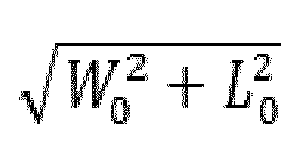
- In this embodiment, to ensure the planning consistency of cells of a route, an
exit grid 1232 and anentrance grid 1231 have the same size; that is, thestock container 202 may also be rotated for direction changeover in theexit grid 1232 such that the rotatedstock container 202 recovers the original orientation. That is, in this embodiment, the lengths of the two-dimensional grids 123 in the first direction in each pickingpassage 121 are same, but the widths of theexit grid 1232 and theentrance grid 1231 in the second direction are greater than that of other two-dimension grids 123 in thepicking passage 121, so as to provide space for thestock container 202 to rotate for direction changeover, and also to improve the space utilization of the pickingzone 10. - This embodiment further provides a picking method, which can implement double-sided picking of a stock container. The picking method provided in this embodiment is as follows.
- Step S2010: an order management center receives a pick-up order, analyzes the position of a
target stock container 202 corresponding to order goods in the pick-up order in astock container zone 20, and at the same time plans atarget picking station 1 corresponding to the pick-up order. - Step S2020: the order management center dispatches a
transfer robot 40, and plans a first traveling route for thetransfer robot 40 according to an initial position of thetransfer robot 40 and the position of thetarget stock container 202. - Step S2030: the
transfer robot 40 travels to the bottom of thetarget stock container 202 according to the first traveling route. - Step S2040: a
lifting mechanism 401 of thetransfer robot 40 operates to cause a pallet to rise and come into contact with the bottom of thestock container 202 until thestock container 202 comes out of contact with the ground. - Step S2050: a control system determines a
target picking passage 121 that thetransfer robot 40 needs to enter according to the congestion oftransfer robots 40 in two pickingpassages 121 in thetarget picking station 1. - Step S2060: the control system plans a second traveling route for the
transfer robot 40 according to the position of an entrance grid of thetarget picking passage 121 and the position of thetarget stock container 202. - Step S2070: the
transfer robot 40 travels to theentrance grid 1231 of thetarget picking passage 121 according to the second traveling route, where during this process, thetarget stock container 202 does not perform direction changeover movement, and thetransfer robot 40 can perform forward movement, backward movement, self-rotation for direction changeover, or the like. - Step S2080: the control system determines whether to perform picking on two sides or one side of the
target stock container 202 according to order information, and if picking is to be performed on one side of thetarget stock container 202 and apicking face 2021 faces away from thepicking point 122, executes step S2090, and if picking is to be performed on one side of thetarget stock container 202 and apicking face 2021 faces thepicking point 122, executes step S2110. - Step S2090: the pallet of the
transfer robot 40 rotates to cause thetarget stock container 202 to rotate 180 °, and then execute step S2100. - Step S2100: the
transfer robot 40 moves forward along a second direction according to an entrance passage to a tail end of theentrance passage 1211, self-rotating 90 ° and traveling along adirection changeover passage 1213 to thepicking point 122. - Step S2110: a picking operator picks target goods on the
target stock container 202. - Step S2120: after the picking is completed, the
transfer robot 40 self-rotates 90 ° for direction changeover and travels along anexit passage 1212 to anexit grid 1232 while carrying thestock container 202. - Step S2130: the control system plans a third traveling route according to the position of the
exit grid 1232 and the position of thetarget stock container 202 in thestock container zone 20, and thetransfer robot 40 transports thestock container 202 back to thestock container zone 20 according to the third traveling route. - Step S2140: the
lifting mechanism 401 of thetransfer robot 40 operates to cause the pallet to descend until thetarget stock container 202 comes into contact with the ground and the pallet comes out of contact with the bottom of thetarget stock container 202. - Step S2150: a driving
mechanism 402 of thetransfer robot 40 operates such that thetransfer robot 40 moves out of the bottom of thestock container 202 and becomes separated from thetarget stock container 202. - In this embodiment, for a
stock container 202 to be picked on one side, if thestock container 202 has been rotated for direction changeover at theentrance grid 1231, thestock container 202 may be rotated for direction changeover at theexit grid 1232 such that the orientation of thestock container 202 is restored to the original position, or direction changeover may alternatively be not performed, and in this case, the orientation of thestock container 202 needs to be updated in the control system. - For a
stock container 202 to be picked on two sides, in this embodiment, after picking is carried out once, it enters theexit grid 1232 and is rotated for direction changeover, and then picking is performed on theother picking face 2021. In other embodiments, it is also possible that after picking is carried out once, it enters theentrance grid 1231 in thepicking passage 121 again, and then is rotated for direction changeover. - In this embodiment, providing the rotation zone is beneficial to implementing the double-sided picking work of the
stock container 202, reducing space occupation of a separate rotation zone, and improving structural compactness and the space utilization of the picking zone. - This embodiment further provides a warehouse logistics system, which includes the above-mentioned stock picking system.
-
Fig. 18 is a schematic structural diagram of a stock picking system provided in an embodiment of the present application. As shown inFig. 18 , this embodiment provides a stock picking system, which is mainly used to implement "goods-to-person" picking of order goods, and may also achieve conventional warehousing and logistics operations such as goods loading and stock check. In this embodiment, the stock picking system includes astock container zone 20, acommon passage 30, a pickingzone 10, and transferrobots 40, where the arrangements of thestock container zone 20, thecommon passage 30, the pickingzone 10, and thetransfer robots 40 are substantially same as in Embodiment II, with the only difference in the configuration of thestock container 202 in thestock container zone 20 and the configuration of the two-dimensional grid 123. Same structures as in Embodiment I will not be repeated in this embodiment. - In this embodiment, when the
stock container 202 is in thestock container zone 20, a pickingface 2021 of thestock container 202 faces alongitudinal passage 203 or faces away from thelongitudinal passage 203. In this case, as the pickingface 2021 of thestock container 202 does not face the pickingzone 10, no matter which pickingface 2021 the target goods are located in, thestock container 202 needs to be rotated such that the pickingface 2021 faces the pickingwork zone 11. Furthermore, if double-sided picking of thestock container 202 is required, after picking is performed on one side, thestock container 202 needs direction changeover, and then picking is carried out on the other side of thestock container 202. - In this embodiment, when the
stock container 202 is stored in thestock container zone 20, the length of thestock container 202 in the first direction is L0, and the width of thestock container 202 in the second direction is W0. To ensure that normal movement of thetransfer robot 40 carrying thestock container 202 in thestock container zone 20, the width L2 of thetransverse passage 204 is greater than L0, and the width W2 of thelongitudinal passage 203 is greater than W0. To ensure rotation of thestock container 202 in the rotation zone, the length L3 of the two-dimensional grid 123 corresponding to the rotation zone in the first direction is greater than W0, and its width W3 in the second direction is greater than
dimensional grid 123 except for the rotation zone in each pickingpassage 121 in the first direction is greater than W0, and its width W1 in the second direction is greater than L0, and to improve the space utilization, W1 is slightly larger than L0, and L1 is slightly larger than W0. - This embodiment further provides a picking method, which is applied to the above-mentioned stock picking system. The picking method provided in this embodiment includes the following steps.
- Step S3010: an order management center receives a pick-up order, analyzes the position of a
target stock container 202 corresponding to order goods in the pick-up order in astock container zone 20, and at the same time plans atarget picking station 1 corresponding to the pick-up order. - Step S3020: the order management center dispatches a
transfer robot 40, and plans a first traveling route for thetransfer robot 40 according to an initial position of thetransfer robot 40 and the position of thetarget stock container 202. - Step S3030: the
transfer robot 40 travels to the bottom of thetarget stock container 202 according to the first traveling route. - Step S3040: a
lifting mechanism 401 of thetransfer robot 40 operates to cause a pallet to rise and come into contact with the bottom of thestock container 202 until thetarget stock container 202 comes out of contact with the ground. - Step S3050: a control system determines a
target picking passage 121 that thetransfer robot 40 needs to enter according to the congestion oftransfer robots 40 in two pickingpassages 121 in thetarget picking station 1. - Step S3060: the control system planning a second traveling route for the
transfer robot 40 according to the position of an entrance grid of thetarget picking passage 121 and the position of thetarget stock container 202. - Step S3070: the
transfer robot 40 travels to theentrance grid 1232 of thetarget picking passage 121 according to the second traveling route, where during this process, thestock container 202 does not perform direction changeover movement, and thetransfer robot 40 can perform forward movement, backward movement, self-rotation for direction changeover, or the like. - Step S3080: the control system determines a rotation angle of the
stock container 202 according to a relationship between the initial orientation of apicking face 2021 corresponding to target goods on thetarget stock container 202 and a work face of apicking point 122. - Step S3090: the pallet of the
transfer robot 40 rotates to cause thestock container 202 to rotate a preset angle. - In this embodiment, the
transfer robot 40 causes thestock container 202 to change direction at theentrance grid 1231 such that the pickingface 2021 is consistent with the work face of thepicking point 122. In other embodiments, it is also possible that when thetransfer robot 40 transports thestock container 202 to thecommon passage 30, thestock container 202 caused to change direction such that onepicking face 2021 of thestock container 202 is consistent with the work face of thepicking point 122. That is, in this embodiment, the first rotation for direction changeover that results in consistency of one picking faces 2021 of thestock container 202 with the work face of thepicking point 122 may occur in thecommon passage 30, or may alternatively occur in theentrance grid 1231 of thepicking passage 121. - Step S3100: the
transfer robot 40 moves forward along a second direction according to an entrance passage to a tail end of the entrance passage, self-rotates 90 ° and travels along adirection changeover passage 1213 to thepicking point 122. - Step S3110: a picking operator picking the target goods on the
target stock container 202. - Step S3120: after the picking is completed, the
transfer robot 40 self-rotates 90 ° for direction changeover and travels along anexit passage 1212 to anexit grid 1232 while carrying thestock container 202. - Step S3130: the control system determines whether the
target stock container 202 is to be picked on two sides, and if thetarget stock container 202 is to be picked on two sides, executes step S3140, and if thetarget stock container 202 is not to be picked on two sides, executes step S3160. - Step S3140: the pallet of the
transfer robot 40 rotates to cause thetarget stock container 202 to rotate 180 °. - Step S3150: the control system determines a
target picking passage 121 that thetransfer robot 40 needs to enter again according to the congestion oftransfer robots 40 in the two pickingpassages 121 in thetarget picking station 1, and the transfer robot enters theentrance grid 1231 of thetarget picking passage 121 from theexit grid 1232 where it is located, passes theentrance passage 1212 and enters thepicking point 122 for picking, and after the picking is completed, the transfer robot passes theexit passage 1212 and moves into theexit grid 1232 of thetarget picking passage 121. - Step S3160: the pallet of the
transfer robot 40 rotates to cause thestock container 202 to rotate a preset angle such that thestock container 202 is restored to the original orientation. - In this embodiment, the
stock container 202 is restored to the original orientation at theexit grid 1232 of thepicking passage 121. In other embodiments, it is also possible that thetransfer robot 40 carrying thestock container 202 moves out of the pickingstation 1 and enters thecommon passage 30, and then causes thestock container 202 to rotate to the initial orientation. - Step S3170: the control system plans a third traveling route according to the position of the
exit grid 1232 and the position of thetarget stock container 202 in thestock container zone 20, and thetransfer robot 40 transports thestock container 202 back to thestock container zone 20 according to the third traveling route. - Step S3180: the
lifting mechanism 401 of thetransfer robot 40 operates to cause the pallet to descend until thetarget stock container 202 comes into contact with the ground and the pallet comes out of contact with the bottom of thestock container 202. - Step S3190: a driving
mechanism 402 of thetransfer robot 40 operates such that thetransfer robot 40 moves out of the bottom of thestock container 202 and becomes separated from thetarget stock container 202. - For a
stock container 202 to be picked on two sides, in this embodiment, after picking is carried out once, it enters theexit grid 1232 and is rotated for direction changeover, and then picking is performed on theother picking face 2021. In other embodiments, it is also possible that after picking is carried out once, it enters the entrance grid in thepicking passage 121 again, and then is rotated for direction changeover. - In this embodiment, providing the rotation zone is beneficial to implementing the double-sided picking work of the
stock container 202, reducing space occupation of a separate rotation zone, and improving structural compactness and the space utilization of the picking zone. - This embodiment further provides a warehousing and logistics system, which includes the above-mentioned stock picking system.
-
Fig. 19 is a schematic structural diagram of a stock picking system provided in an embodiment of the present application, andFig. 20 is a schematic structural diagram of a picking station and a stock container provided in an embodiment of the present application. As shown inFigs. 19 and20 , this embodiment provides a stock picking system, which is mainly used to implement "goods-to-person" picking of order goods, and may also achieve conventional warehousing and logistics operations such as goods loading and stock check. In this embodiment, the stock picking system includes astock container zone 20, acommon passage 30, a pickingzone 10, and transferrobots 40, where the arrangements of thestock container zone 20, thecommon passage 30, the pickingzone 10, and thetransfer robots 40 are substantially same as in the Embodiment I, with the only difference in the configuration of the pickingzone 10. Same structures as in the Embodiment I will not be repeated in this embodiment. - In this embodiment, the
stock container 202 has two picking faces 2021 opposite to each other, where one of the two picking faces 2021 faces alongitudinal passage 203, and the other faces away from thelongitudinal passage 203 adjacent thereto. Eachpartition layer 2022 of thestock container 202 can be provided with one or a plurality ofstorage containers 50 side by side along the second direction. - In this embodiment, each picking
station 1 includes two pickingpoints 122 and two pickingpassages 121, where each pickingpassage 122 forms a U shape, and both an entrance and an exit of thepicking passage 122 face thestock container zone 20. The two picking passages are spaced apart from each other, and a pickingwork zone 11 for a picking operator to move is formed between the two picking passages. Thepicking point 122 is located on a side of the U shape of thepicking passage 121, and thepicking point 122 faces the pickingwork zone 11. - In this configuration, as the
picking point 122 is located on a side of the pickingwork zone 11, when thetransfer robot 40 transports thestock container 202 from thestock container zone 20 to thepicking point 122, rotation of thestock container 202 may be not needed to enable apicking face 2021 of thestock container 202 to face the pickingwork zone 11, thus improving the picking efficiency and avoiding an increase in space caused by providing an additional rotation zone. Furthermore, the picking points 122 and the pickingpassages 121 are provided on two sides of the pickingwork zone 11, so that the same picking operator can be responsible for the picking on the twopicking points 122, and after the picking of astock container 202 on onepicking point 122 is completed and the transfer robot entered from the pickingpassage 121 has not conveyed astock container 202 to thepicking point 122, the picking operator can perform picking on astock container 202 waiting for picking on theother picking point 122, thereby reducing the idle waiting time of the picking operator, and improving the picking efficiency. - In an embodiment, in the two picking
passages 121, one pickingpassage 121 is arranged clockwise, and theother picking passage 121 is arranged counterclockwise. That is, bothentrance passages 1211 of the two pickingpassages 121 are located on a side of thepicking passage 121 adjacent to the pickingwork zone 11, or bothexit passages 1212 of the two pickingpassages 121 are located on a side of thepicking passage 121 adjacent to the pickingwork zone 11. In this configuration, if thetransfer robot 40 transports thestock container 202 to the picking points 122 ofdifferent picking passages 121, the pickingface 2021 facing the pickingwork zone 11 is different in each case. That is, according to the orientation of the pickingface 2021 corresponding to the target goods on thestock container 202, one of the two pickingpassages 121 can be selected to enter the pickingstation 1, so that when thestock container 202 is located at thepicking point 122, the pickingface 2021 where the target goods is located faces directly toward the pickingwork zone 11, to facilitate picking by the picking person. This is beneficial for picking of astock container 202 to be picked on both sides, avoiding rotation for direction changeover of thestock container 202 during the process of transporting by thetransfer robot 40, and improving the picking efficiency. - In this embodiment, on a side of the picking
work zone 11 facing thestock container zone 20, the pickingstation 1 is provided with acommunication passage 124 that communicates the two pickingpassages 121, and thecommunication passage 124 is formed by two logically divided two-dimensional grids, and the two two-dimensional grids of the communication passage and theentrance grids 1231 and theexit grids 1232 are arranged side by side to achieve communication between the two pickingpassages 121, so that thetransfer robot 40 does not need to move out of the pickingstation 1 to achieve movement between the two pickingpassages 122 in thesame picking station 1, thereby implementing the double-sided picking operation of thestock container 202. - In an embodiment, each of the
entrance passages 1211 of the two pickingpassages 121 is located on a side of thepicking passage 121 adjacent to the pickingwork zone 11, and twoadjacent picking passages 121 of twoadjacent picking stations 1 share oneexit passage 1212. This configuration can improve the compactness of the arrangement of the pickingstations 1 in the pickingzone 10 and save space. - In an embodiment, each column of two-dimensional grid group includes four two-
dimensional grids 123 to improve the space utilization of the pickingzone 10 and the space compactness of the stock picking system. In an embodiment, the third two-dimensional grid 123 along the direction of theentrance passage 1211 forms thepicking point 122. In this configuration, on the one hand, the first two two-dimensional grids 123 can be used for thetransfer robot 40 to enter thepicking passage 121 and wait in thepicking passage 121, thereby increasing the number oftransfer robots 40 that may wait in thepicking passage 121; on the other hand, this facilitates providing putwalls 112 on two sides of thepicking point 122 along the second direction, so that the picking operator can quickly take the target goods on thestock container 202 in the picking work and put the goods into an order box of the putwall 112. In another embodiment, thepicking point 122 may also be formed by a two-dimensional grid 123 at the tail end of theentrance passage 1211 away from theentrance grid 1231. - The length of the
stock container 202 in the first direction is L0, and the width of thestock container 202 in the second direction is W0. To ensure the transporting of thestock container 202 in thestock container zone 20, the width L2 of thetransverse passage 204 is greater than L0, and the width W2 of thelongitudinal passage 203 is greater than W0. To ensure the traveling of thestock container 202 in the pickingzone 10 and avoid collision during the traveling of thetransfer robot 40, the length L1 of each two-dimensional grid 123 along the first direction is greater than L0, and the width W1 of each two-dimensional grid 123 in the second direction is greater than W0. Furthermore, to improve the space utilization, W1 is slightly larger than W0, and Li is slightly larger than L0. - In an embodiment, to improve the planning consistency of the picking
zone 10, each two-dimensional grid 123 is identical. - In an embodiment, one
put wall 112 is provided in the pickingwork zone 11, and the putwall 112 is located between two pickingpoints 122, and the putwall 112 is oriented away from thestock container zone 20. In other implementations, the pickingwork zone 11 may be provided with two putwalls 112, and the two putwalls 112 are arranged oppositely, and are respectively located on two sides of thepicking point 122 along the second direction. - In this embodiment, as a
picking face 2021 of thestock container 202 in thestock container zone 20 faces toward or away from thelongitudinal passage 203, the initial orientation of the pickingface 2021 of thestock container 202 in thestock container zone 20 is same as the orientation of the work face of thepicking point 122. That is, during the process of transporting thestock container 202 by thetransfer robot 40, thestock container 202 does not need to change direction. In other embodiments, the placement position of thestock container 202 in thestock container zone 20 may be not limited, and before thetransfer robot 40 transports thestock container 202 to the pickingstation 1, it can cause thestock container 202 to be rotated for direction changeover such that the pickingface 2021 of thestock container 202 is oriented same as the work face of thepicking point 122. - This embodiment further provides a picking method, which is applied to the above-mentioned stock picking system, and can implement picking on two sides of the
stock container 202. The picking method includes the following steps. - Step S4010: Tan order management center receives a pick-up order, analyzes the position of a
target stock container 202 corresponding to order goods in the pick-up order in astock container zone 20, and at the same time plans atarget picking station 1 corresponding to the pick-up order. - Step S4020: the order management center dispatches a
transfer robot 40, and plans a first traveling route for thetransfer robot 40 according to an initial position of thetransfer robot 40 and the position of thetarget stock container 202. - Step S4030: the
transfer robot 40 travels to the bottom of thetarget stock container 202 according to the first traveling route. - Step S4040: a
lifting mechanism 401 of thetransfer robot 40 operates to cause a pallet to rise and come into contact with the bottom of thestock container 202 until thetarget stock container 202 comes out of contact with the ground. - Step S4050: the control system determines whether the
target stock container 202 is to be picked on two sides, and if thetarget stock container 202 is to be picked on two sides, determines atarget picking passage 121 to enter according to the congestion in the two pickingpassages 121 in thetarget picking station 1, and if thetarget stock container 202 is not to be picked on two sides, determines atarget picking passage 121 to enter according to the orientation of apicking face 2021 of thetarget stock container 202. - Step S4060: the control system plans a second traveling route for the
transfer robot 40 according to the position of an entrance grid of thetarget picking passage 121 and the position of thetarget stock container 202. - Step S4070: the
transfer robot 40 travels to the entrance grid of thetarget picking passage 121 according to the second traveling route, where during this process, thetarget stock container 202 does not perform direction changeover movement, and thetransfer robot 40 can perform forward movement, backward movement, self-rotation for direction changeover, or the like. - In this embodiment, the initial orientation of the
stock container 202 in thestock container zone 20 is consistent with the orientation of the work face of one of the picking points 122, so thestock container 202 does not need to change direction. In other embodiments, if the initial orientation of thestock container 202 in thestock container zone 20 is different from the orientation of the work face of any of the twopicking points 122, thetransfer robot 40 can rotate thestock container 202 for direction changeover before carrying thestock container 202 into the pickingstation 1, such that the pickingface 2021 of thestock container 202 is oriented the same as the work face of one of the picking points 122. - Step S4080: the
transfer robot 40 moves forward along a second direction according to an entrance passage to thepicking point 122. - Step S4090: a picking operator picks the target goods on the
target stock container 202. - Step S4100: after the picking is completed, the
transfer robot 40 travels along adirection changeover passage 1213 and anexit passage 1212 to anexit grid 1232. - Step S4110: the control system determines whether the
stock container 202 is to be picked on two sides, and if thetarget stock container 202 is to be picked on two sides, executes step S4120, and if thetarget stock container 202 is not to be picked on two sides, executes step S4130. - Step S4120: the
transfer robot 40 enters theother picking passage 121 through acommunication passage 124, and travels to thecorresponding picking point 122 while carrying thetarget stock container 202 to be picked by the picking operator, and after the picking is completed, passes theexit passage 1212 and moves into theexit grid 1232 of thetarget picking passage 121. - Step S4130: the control system plans a third traveling route according to the position of the
exit grid 1232 and the position of thetarget stock container 202 in thestock container zone 20, and thetransfer robot 40 transports thetarget stock container 202 back to thestock container zone 20 according to the third traveling route. - Step S4140: the
lifting mechanism 401 of thetransfer robot 40 operates to cause the pallet to descend until thetarget stock container 202 comes into contact with the ground and the pallet comes out of contact with the bottom of thetarget stock container 202. - Step S4150: a driving
mechanism 402 of thetransfer robot 40 operates such that thetransfer robot 40 moves out of the bottom of thetarget stock container 202 and becomes separated from thestock container 202. - This embodiment further provides a warehousing and logistics system, which includes the above-mentioned stock picking system.
Claims (15)
- A stock picking system, comprising:a stock container zone (20) configured to store a plurality of stock containers (202);a transfer robot (40) configured to transport the stock containers (202); anda picking zone (10) configured for a picking operator to pick target goods from the stock container (202) transported by the transfer robot (40); wherein:the picking zone (10) comprises at least one picking station (1), each picking station (1) comprising two picking passages (121) and two picking points (122) respectively located on the two picking passages (121);each picking point (122) is configured for the picking operator to pick the target goods;each picking passage (121) is U-shaped and configured to provide a traveling route for the transfer robot (40) to enter the picking station (1) and pass through the picking point (122) on each picking passage (121) in each picking station (1) and leave the picking station (1).
- The stock picking system according to claim 1, wherein the two picking passages (121) are arranged side by side or in parallel, and the two picking points (122) are respectively located at bottoms of the U shapes of the two picking passages (121), and a picking work zone (11) for a picking operator to move is formed at an end of the two picking passages (121) away from the stock container zone (20).
- The stock picking system according to claim 2, wherein the two picking passages (121) are arranged adjacent to each other;
and preferably, wherein the two picking points (122) are arranged adjacent to each other. - The stock picking system according to claim 3, wherein the picking work zone (11) is provided with two put walls (112) opposite to each other, each put wall (112) accommodating a plurality of order containers, and the two picking points (122) are located in an extension space formed by the two put walls (112).
- The stock picking system according to claim 1, wherein the two picking passages (121) in each picking station (1) are spaced apart from each other; the two picking points (122) are respectively located on lateral sides of the U shapes of the two picking passages (121) and are arranged oppositely, and a picking work zone (11) for a picking operator to move is formed between the two picking passages (121);
and preferably, wherein a picking face (2021) of the stock container (202) located in the picking zone (10) is parallel to lateral sides of the U shape of each picking passage (121). - The stock picking system according to any one of claims 2 to 5, wherein one picking passage (121) of the two picking passages (121) provides a traveling route in a clockwise direction, and the other picking passage (121)) provides a traveling route in a counterclockwise direction.
- The stock picking system according to any one of claims 3 or 4, wherein each picking passage (121) has an entrance grid (1231) forming an entrance of the picking passage (121) and an exit grid (1232) forming an exit of the picking passage (121), and a traveling width of the entrance grid (1231) and the exit grid (1232) is larger than a maximum outer diameter of the stock container (202).
- The stock picking system according to any one of claims 3 to 5, wherein each picking passage (121) comprises an entrance passage (1211) and an exit passage (1212) forming two lateral sides of the U shape; the exit passage (1212) is located on a side of the picking passage (121) adjacent to another picking station (1); and the adjacent two picking stations (1) share one exit passage (1212).
- The stock picking system according to claim 1, wherein the stock container zone (20) and the picking zone (10) are logically provided with two-dimensional grids, and one two-dimensional grid in the picking zones (10) corresponds to one of the picking points (122).
- The stock picking system according to claim 9, wherein in each picking passage (121), the two-dimensional grids located upstream of the picking point (122) on the picking passage (121) form an area for the transfer robot (40) to pass and wait.
- The stock picking system according to claim 9, wherein a reference mark is provided at a center of at least one of the two-dimensional grids for positioning by the transfer robot (40).
- The stock picking system according to claim 1, wherein a layout mode of picking station (1) comprises one of:
a dual-station symmetrical layout mode, a parallel layout mode, or a mode of queuing with no specific rotation zone. - The stock picking system according to claim 12, wherein in a case where the layout mode of the picking station (1) comprises the dual-station symmetrical layout mode, the picking station (1) comprises two rotation zones, the two picking passages (121) being around the two rotation zones respectively, the two picking passages (121) being partially overlapped to form a passage area between the two rotation zones, each picking passage (121) being provided with an entrance position, an operation position, a plurality of rotation zone entry positions, a plurality of queuing return positions, and an exit position, wherein the operation position is a position where the transfer robot (40) transporting the stock containers (202) waits for the picking operator's operation; the rotation zone entry position is a position allowing the transfer robot (40) to enter the rotation zone from the picking passage (121); the queuing return position is a position allowing the transfer robot (40) to enter the picking passage (121) from the rotation zone; the entrance position is set in the passage area, the two picking passages (121) sharing one entrance position; and the rotation zone entry positions, the queuing return positions and the exit positions on the two picking passages (121) are symmetrically arranged on two sides of the passage area; orin a case where the layout mode of the picking station (1) comprises the parallel layout mode, the picking station (1) comprises two rotation zones, the two picking passages (121) being around the two rotation zones respectively, each picking passage (121) being provided with an entrance position, an operation position, a plurality of rotation zone entry positions, a plurality of queuing return positions, and an exit position, the two picking passages (121) being arranged in parallel, wherein the operation position is a position where the transfer robot (40) transporting the stock container (202) waits for the picking operator's operation; the rotation zone entry position is a position allowing the transfer robot (40) to enter the rotation zone from the picking passage (121); and the queuing return position is a position allowing the transfer robot (40) to enter the picking passage (121) from the rotation zone; orin a case where the layout mode of the picking station (1) comprises a mode of queuing with no specific rotation zone, each picking passage (121) is used as a rotation zone, the picking passage (121) being provided with an operation position, an exit position, and a plurality of entrance positions, the plurality of entrance positions being located between the operation position and the exit position.
- The stock picking system according to claim 1, further comprising: a shelf management apparatus configured to perform real-time detection on a surrounding environment where the stock container is located within a traveling route from allocation to completion of a transport task, and control the transfer robot (40) to perform a rotation operation on the stock container in response to detecting that the surrounding environment is suitable for rotation.
- The stock picking system according to claim 14, wherein the shelf management apparatus is further configured to: control the transfer robot (40) to perform the rotation operation in a transporting route, at a rotation point set in the picking station, or in situ at an operation position;
and preferably, the shelf management apparatus is further configured to:during walking on a route of the transfer robot (40), detect whether a cell near a route point ahead is occupied, and in response to the cell near the route point ahead being possible to be applied for at the same time, use the route point as a rotation point;when the transfer robot (40) arrives at the rotation point, occupy a surrounding cell, and in response to the occupation is unsuccessful, control the transfer robot (40) to continue to walk;before the transfer robot (40) arrives at a picking point (122), if the stock container (202) is not rotated on the route, control the transfer robot (40) to enter a rotation zone set for the picking point (122); andin a case where the stock container (202) that has been rotated still needs to be rotated, determine in situ whether a surrounding cell is possible to be occupied, and in response to the surrounding cell being possible to be occupied, control the transfer robot (40) to occupy the surrounding cell, and in response to the surrounding cell being not possible to be occupied, control the transfer robot (40) to enter the picking station (1) again and continue to queue and enter a rotation point;and preferably, a straightline and arc line tangent route or a polyline route is used in the rotation zone to perform stock container rotation.
Applications Claiming Priority (4)
| Application Number | Priority Date | Filing Date | Title |
|---|---|---|---|
| CN201810577628.6A CN108945920A (en) | 2018-06-06 | 2018-06-06 | Rack queuing and rotation method, device and system |
| CN201910354343.0A CN109928131B (en) | 2019-04-29 | 2019-04-29 | Sorting area and inventory sorting system |
| PCT/CN2019/090424 WO2019233484A1 (en) | 2018-06-06 | 2019-06-06 | Shelf management method and system, pickup area, and stock pickup system |
| EP19814838.9A EP3805131B1 (en) | 2018-06-06 | 2019-06-06 | Shelf management method and system, pickup area, and stock pickup system |
Related Parent Applications (2)
| Application Number | Title | Priority Date | Filing Date |
|---|---|---|---|
| EP19814838.9A Division EP3805131B1 (en) | 2018-06-06 | 2019-06-06 | Shelf management method and system, pickup area, and stock pickup system |
| EP19814838.9A Division-Into EP3805131B1 (en) | 2018-06-06 | 2019-06-06 | Shelf management method and system, pickup area, and stock pickup system |
Publications (3)
| Publication Number | Publication Date |
|---|---|
| EP4292881A2 true EP4292881A2 (en) | 2023-12-20 |
| EP4292881A3 EP4292881A3 (en) | 2024-02-28 |
| EP4292881B1 EP4292881B1 (en) | 2026-02-04 |
Family
ID=68770799
Family Applications (2)
| Application Number | Title | Priority Date | Filing Date |
|---|---|---|---|
| EP19814838.9A Active EP3805131B1 (en) | 2018-06-06 | 2019-06-06 | Shelf management method and system, pickup area, and stock pickup system |
| EP23207305.6A Active EP4292881B1 (en) | 2018-06-06 | 2019-06-06 | Stock pickup system |
Family Applications Before (1)
| Application Number | Title | Priority Date | Filing Date |
|---|---|---|---|
| EP19814838.9A Active EP3805131B1 (en) | 2018-06-06 | 2019-06-06 | Shelf management method and system, pickup area, and stock pickup system |
Country Status (11)
| Country | Link |
|---|---|
| US (2) | US12162736B2 (en) |
| EP (2) | EP3805131B1 (en) |
| JP (2) | JP6957772B2 (en) |
| KR (1) | KR102581222B1 (en) |
| AU (1) | AU2019281676B9 (en) |
| CA (1) | CA3102308C (en) |
| DE (1) | DE202019006215U1 (en) |
| ES (1) | ES3063901T3 (en) |
| MX (1) | MX2020013234A (en) |
| PL (1) | PL4292881T3 (en) |
| WO (1) | WO2019233484A1 (en) |
Families Citing this family (27)
| Publication number | Priority date | Publication date | Assignee | Title |
|---|---|---|---|---|
| JP6816068B2 (en) * | 2018-07-06 | 2021-01-20 | ファナック株式会社 | Robot program generator |
| NZ781258A (en) * | 2019-04-08 | 2022-07-01 | Lineage Logistics Llc | Automatic transportation of pallets of goods |
| US20210133667A1 (en) * | 2019-11-06 | 2021-05-06 | Walmart Apollo, Llc | Systems and methods for processing online product orders |
| CN111461547B (en) | 2020-03-31 | 2024-06-18 | 北京京邦达贸易有限公司 | Order scheduling method, system, device and electronic equipment |
| CN111638716B (en) * | 2020-05-29 | 2024-02-23 | 北京极智嘉科技股份有限公司 | Inventory management method and system |
| CN112193704B (en) | 2020-10-10 | 2021-06-29 | 深圳市海柔创新科技有限公司 | Warehousing system, cargo carrying method, control terminal, robot and storage medium |
| CN112371518B (en) * | 2020-10-15 | 2022-04-05 | 北京极智嘉科技股份有限公司 | Item sorting system and method |
| US12319503B2 (en) * | 2021-01-15 | 2025-06-03 | Thanh Dang Nguyen | Automated package delivery devices, machines, and systems |
| US20220227580A1 (en) * | 2021-01-15 | 2022-07-21 | Thanh Dang Nguyen | Automated package delivery devices, machines, and systems |
| CN113753462B (en) * | 2021-09-14 | 2023-04-11 | 深圳市库宝软件有限公司 | Task allocation method, device, equipment, warehousing system and storage medium |
| JP7802479B2 (en) * | 2021-09-24 | 2026-01-20 | 株式会社東芝 | Shelf processing system and shelf transport control system |
| CN114275430B (en) * | 2021-11-23 | 2024-07-02 | 杭州拼便宜网络科技有限公司 | Warehouse task processing method, device, equipment and storage medium |
| CN114565266B (en) * | 2022-02-24 | 2025-04-18 | 江苏国范智能科技有限公司 | A clothing order matching system and method |
| TWI790934B (en) * | 2022-03-03 | 2023-01-21 | 優式機器人股份有限公司 | The method of robot avoiding obstacle |
| JP7755046B2 (en) * | 2022-03-23 | 2025-10-15 | 株式会社東芝 | Indication device, handling system, handling method, program, and storage medium |
| IL293899B2 (en) * | 2022-06-13 | 2025-09-01 | Caja Elastic Dynamic Solutions Ltd | Task manager system and a method thereof |
| CN115309123B (en) * | 2022-09-09 | 2025-08-19 | 北京京东乾石科技有限公司 | Method and device for scheduling robots in tunnel and storage medium |
| CN115367364A (en) * | 2022-09-29 | 2022-11-22 | 上海木蚁机器人科技有限公司 | Warehouse management system |
| JP7622720B2 (en) * | 2022-10-07 | 2025-01-28 | トヨタ自動車株式会社 | Sorting system, sorting method, and program |
| CN115672748A (en) * | 2022-10-25 | 2023-02-03 | 深圳进化动力数码科技有限公司 | Method, device, equipment and storage medium for judging the position of fresh food sorting robot |
| CN118255087A (en) * | 2022-12-28 | 2024-06-28 | 中光电智能物流股份有限公司 | Shelf positioning method of handling device and handling device capable of positioning shelf |
| CN117079371B (en) * | 2023-10-13 | 2024-04-05 | 成都越凡创新科技有限公司 | Scheduling method and system for access control rights |
| KR20250089318A (en) * | 2023-12-11 | 2025-06-18 | 현대자동차주식회사 | Electronic device and control method thereof |
| KR102687351B1 (en) | 2023-12-14 | 2024-07-23 | 주식회사 트위니 | Server for allocating robot to picking zone in precess of managing plurality of orders simultaneously, and system thereof |
| KR102734722B1 (en) * | 2024-04-08 | 2024-11-27 | 주식회사 솔루엠 | A moving robot for monitoring a shelf, a method for monitoring a shelf, and a system for monitoring a shelf |
| CN118479179A (en) * | 2024-05-22 | 2024-08-13 | 湖南省烟草公司衡阳市公司 | Tobacco stock method |
| CN120172031B (en) * | 2025-05-21 | 2025-09-02 | 杭州海康机器人股份有限公司 | Workstation, robot scheduling method and device for workstation |
Family Cites Families (28)
| Publication number | Priority date | Publication date | Assignee | Title |
|---|---|---|---|---|
| JPS6171723A (en) * | 1984-09-14 | 1986-04-12 | Nec Corp | Digital-analog converter measuring system |
| DE3922964A1 (en) * | 1989-07-12 | 1991-01-17 | Keuro Maschinenbau Gmbh | METHOD AND DEVICE FOR REMOVING AND STORING CASSETTES CONTAINING RODS OR PLATE-SHAPED MATERIAL FROM A SHELVING STORAGE |
| JP2563053B2 (en) | 1992-12-03 | 1996-12-11 | 村田機械株式会社 | Picking system |
| US7132237B2 (en) | 2002-03-13 | 2006-11-07 | Mayo Foundation For Medical Education And Research | Avian leukosis viruses and polypeptide display |
| US8483869B2 (en) | 2005-07-19 | 2013-07-09 | Amazon Technologies, Inc. | Method and system for fulfilling requests in an inventory system |
| US9330373B2 (en) * | 2005-07-19 | 2016-05-03 | Amazon Technologies, Inc. | Method and system for storing inventory holders |
| US7894933B2 (en) * | 2005-07-19 | 2011-02-22 | Kiva Systems, Inc. | Method and system for retrieving inventory items |
| WO2007011814A2 (en) | 2005-07-19 | 2007-01-25 | Kiva Systems, Inc. | Method and system for storing inventory holders |
| US7894932B2 (en) * | 2005-07-19 | 2011-02-22 | Kiva Systems, Inc. | Method and system for replenishing inventory items |
| US20130302132A1 (en) * | 2012-05-14 | 2013-11-14 | Kiva Systems, Inc. | System and Method for Maneuvering a Mobile Drive Unit |
| US8220710B2 (en) | 2006-06-19 | 2012-07-17 | Kiva Systems, Inc. | System and method for positioning a mobile drive unit |
| DE102010022678A1 (en) | 2010-06-04 | 2011-12-08 | Jungheinrich Aktiengesellschaft | Horizontal order |
| WO2012032866A1 (en) | 2010-09-09 | 2012-03-15 | 村田機械株式会社 | Picking system and picking method |
| US8965562B1 (en) * | 2013-09-09 | 2015-02-24 | Amazon Technologies, Inc. | Efficient shuffling of mobile drive units for inventory holders |
| EP3056453A4 (en) * | 2013-10-11 | 2017-07-26 | Hitachi, Ltd. | Transport vehicle control device and transport vehicle control method |
| DE102014102092A1 (en) | 2014-02-19 | 2015-08-20 | Dematic Gmbh | Method and station for picking articles according to the goods-to-man principle |
| US9111251B1 (en) * | 2014-03-31 | 2015-08-18 | Amazon Technologies, Inc. | Shuffling inventory holders |
| JP2016055963A (en) | 2014-09-08 | 2016-04-21 | 株式会社日立製作所 | Arrival and shipment support system, unmanned vehicle and arrival and shipment support method |
| CN104555222A (en) | 2014-12-25 | 2015-04-29 | 北京物资学院 | Storage and distribution integration system and method based on insert-type AGV |
| US9378482B1 (en) * | 2015-03-13 | 2016-06-28 | Amazon Technologies, Inc. | Exchange of containers |
| US10513033B2 (en) | 2016-03-25 | 2019-12-24 | Locus Robotics Corp. | Robot queuing in order fulfillment operations |
| JP6739299B2 (en) | 2016-09-13 | 2020-08-12 | 株式会社日立製作所 | Transport system and transport method |
| CN106843238A (en) * | 2017-04-10 | 2017-06-13 | 锥能机器人(上海)有限公司 | A kind of warehouse automation sorting system and method |
| CN107235276B (en) * | 2017-06-05 | 2019-06-04 | 北京京东尚科信息技术有限公司 | Cargo handling method and device |
| JP6937200B2 (en) | 2017-09-12 | 2021-09-22 | 株式会社東芝 | Article movement device, article movement method, and article movement control program |
| CN108100548B (en) * | 2017-11-10 | 2020-04-24 | 北京科捷物流有限公司 | Automatic sorting method and system for storage robot |
| CN110348749B (en) | 2018-06-06 | 2023-04-18 | 北京极智嘉科技股份有限公司 | Queuing method and system for goods shelf |
| CN109359924A (en) | 2018-11-19 | 2019-02-19 | 炬星科技(深圳)有限公司 | Robot-based logistics partition picking method, device, terminal, system and storage medium |
-
2019
- 2019-06-06 PL PL23207305.6T patent/PL4292881T3/en unknown
- 2019-06-06 US US16/972,003 patent/US12162736B2/en active Active
- 2019-06-06 ES ES23207305T patent/ES3063901T3/en active Active
- 2019-06-06 WO PCT/CN2019/090424 patent/WO2019233484A1/en not_active Ceased
- 2019-06-06 DE DE202019006215.7U patent/DE202019006215U1/en active Active
- 2019-06-06 EP EP19814838.9A patent/EP3805131B1/en active Active
- 2019-06-06 CA CA3102308A patent/CA3102308C/en active Active
- 2019-06-06 AU AU2019281676A patent/AU2019281676B9/en active Active
- 2019-06-06 JP JP2020568239A patent/JP6957772B2/en active Active
- 2019-06-06 KR KR1020217000360A patent/KR102581222B1/en active Active
- 2019-06-06 MX MX2020013234A patent/MX2020013234A/en unknown
- 2019-06-06 EP EP23207305.6A patent/EP4292881B1/en active Active
-
2021
- 2021-10-06 JP JP2021164805A patent/JP7084538B2/en active Active
-
2024
- 2024-10-24 US US18/925,586 patent/US20250051149A1/en active Pending
Also Published As
| Publication number | Publication date |
|---|---|
| JP2021520329A (en) | 2021-08-19 |
| KR102581222B1 (en) | 2023-09-21 |
| AU2019281676B9 (en) | 2023-02-02 |
| US20210323800A1 (en) | 2021-10-21 |
| WO2019233484A1 (en) | 2019-12-12 |
| JP2022002999A (en) | 2022-01-11 |
| JP7084538B2 (en) | 2022-06-14 |
| US20250051149A1 (en) | 2025-02-13 |
| MX2020013234A (en) | 2021-02-22 |
| DE202019006215U1 (en) | 2026-04-02 |
| EP4292881A3 (en) | 2024-02-28 |
| JP6957772B2 (en) | 2021-11-02 |
| EP4292881B1 (en) | 2026-02-04 |
| CA3102308C (en) | 2023-08-01 |
| EP3805131A1 (en) | 2021-04-14 |
| US12162736B2 (en) | 2024-12-10 |
| KR20210016464A (en) | 2021-02-15 |
| AU2019281676A1 (en) | 2021-01-07 |
| EP3805131A4 (en) | 2022-06-29 |
| PL4292881T3 (en) | 2026-07-20 |
| AU2019281676B2 (en) | 2022-10-06 |
| CA3102308A1 (en) | 2019-12-12 |
| EP3805131B1 (en) | 2023-12-13 |
| ES3063901T3 (en) | 2026-04-21 |
Similar Documents
| Publication | Publication Date | Title |
|---|---|---|
| EP3805131B1 (en) | Shelf management method and system, pickup area, and stock pickup system | |
| JP6829779B2 (en) | Warehouse management system and method | |
| KR102813120B1 (en) | Navigation route reservation for warehouse robot | |
| JP7018547B2 (en) | A warehouse management system and method that integrates the preparation and sorting of goods. | |
| CN109928131B (en) | Sorting area and inventory sorting system | |
| CN111771176A (en) | Controller and method for transporting equipment | |
| CN108945920A (en) | Rack queuing and rotation method, device and system | |
| CN111861325A (en) | Storage system and storage control method | |
| JPS5931220A (en) | Multiline feeding mechanism for ic magazines | |
| JP2003285906A (en) | Transport system | |
| WO2025246768A1 (en) | Container handling method and apparatus, and warehousing system | |
| JP7798090B2 (en) | Goods transport equipment | |
| JP7822828B2 (en) | system | |
| HK40054136A (en) | Warehousing management system and method | |
| WO2025165533A1 (en) | Automatic storage and retrieval systems and methods having staging, sequencing and buffer systems and methods | |
| JP2025068825A (en) | Article sorting installation | |
| WO2025088855A1 (en) | Article sorting facility |
Legal Events
| Date | Code | Title | Description |
|---|---|---|---|
| PUAI | Public reference made under article 153(3) epc to a published international application that has entered the european phase |
Free format text: ORIGINAL CODE: 0009012 |
|
| STAA | Information on the status of an ep patent application or granted ep patent |
Free format text: STATUS: THE APPLICATION HAS BEEN PUBLISHED |
|
| AC | Divisional application: reference to earlier application |
Ref document number: 3805131 Country of ref document: EP Kind code of ref document: P |
|
| AK | Designated contracting states |
Kind code of ref document: A2 Designated state(s): AL AT BE BG CH CY CZ DE DK EE ES FI FR GB GR HR HU IE IS IT LI LT LU LV MC MK MT NL NO PL PT RO RS SE SI SK SM TR |
|
| REG | Reference to a national code |
Ref country code: DE Ref legal event code: R079 Free format text: PREVIOUS MAIN CLASS: B60P0001000000 Ipc: G05D0001000000 Ref country code: DE Ref legal event code: R079 Ref document number: 602019081158 Country of ref document: DE Free format text: PREVIOUS MAIN CLASS: B60P0001000000 Ipc: G05D0001000000 |
|
| PUAL | Search report despatched |
Free format text: ORIGINAL CODE: 0009013 |
|
| AK | Designated contracting states |
Kind code of ref document: A3 Designated state(s): AL AT BE BG CH CY CZ DE DK EE ES FI FR GB GR HR HU IE IS IT LI LT LU LV MC MK MT NL NO PL PT RO RS SE SI SK SM TR |
|
| RIC1 | Information provided on ipc code assigned before grant |
Ipc: B60P 1/00 20060101ALI20240122BHEP Ipc: B65G 1/137 20060101ALI20240122BHEP Ipc: B65G 1/04 20060101ALI20240122BHEP Ipc: G06Q 10/08 20230101ALI20240122BHEP Ipc: G06Q 10/04 20230101ALI20240122BHEP Ipc: G05D 1/00 20060101AFI20240122BHEP |
|
| STAA | Information on the status of an ep patent application or granted ep patent |
Free format text: STATUS: REQUEST FOR EXAMINATION WAS MADE |
|
| 17P | Request for examination filed |
Effective date: 20240822 |
|
| RBV | Designated contracting states (corrected) |
Designated state(s): AL AT BE BG CH CY CZ DE DK EE ES FI FR GB GR HR HU IE IS IT LI LT LU LV MC MK MT NL NO PL PT RO RS SE SI SK SM TR |
|
| GRAP | Despatch of communication of intention to grant a patent |
Free format text: ORIGINAL CODE: EPIDOSNIGR1 |
|
| STAA | Information on the status of an ep patent application or granted ep patent |
Free format text: STATUS: GRANT OF PATENT IS INTENDED |
|
| INTG | Intention to grant announced |
Effective date: 20250819 |
|
| GRAS | Grant fee paid |
Free format text: ORIGINAL CODE: EPIDOSNIGR3 |
|
| GRAA | (expected) grant |
Free format text: ORIGINAL CODE: 0009210 |
|
| STAA | Information on the status of an ep patent application or granted ep patent |
Free format text: STATUS: THE PATENT HAS BEEN GRANTED |
|
| AC | Divisional application: reference to earlier application |
Ref document number: 3805131 Country of ref document: EP Kind code of ref document: P |
|
| AK | Designated contracting states |
Kind code of ref document: B1 Designated state(s): AL AT BE BG CH CY CZ DE DK EE ES FI FR GB GR HR HU IE IS IT LI LT LU LV MC MK MT NL NO PL PT RO RS SE SI SK SM TR |
|
| REG | Reference to a national code |
Ref country code: CH Ref legal event code: F10 Free format text: ST27 STATUS EVENT CODE: U-0-0-F10-F00 (AS PROVIDED BY THE NATIONAL OFFICE) Effective date: 20260204 Ref country code: GB Ref legal event code: FG4D |
|
| REG | Reference to a national code |
Ref country code: DE Ref legal event code: R096 Ref document number: 602019081158 Country of ref document: DE |
|
| REG | Reference to a national code |
Ref country code: IE Ref legal event code: FG4D Ref country code: NL Ref legal event code: FP |
|
| REG | Reference to a national code |
Ref country code: CH Ref legal event code: R17 Free format text: ST27 STATUS EVENT CODE: U-0-0-R10-R17 (AS PROVIDED BY THE NATIONAL OFFICE) Effective date: 20260227 |
|
| P01 | Opt-out of the competence of the unified patent court (upc) registered |
Free format text: CASE NUMBER: UPC_APP_0002730_4292881/2026 Effective date: 20260126 |
|
| REG | Reference to a national code |
Ref country code: ES Ref legal event code: FG2A Ref document number: 3063901 Country of ref document: ES Kind code of ref document: T3 Effective date: 20260421 |
|
| REG | Reference to a national code |
Ref country code: CH Ref legal event code: U11 Free format text: ST27 STATUS EVENT CODE: U-0-0-U10-U11 (AS PROVIDED BY THE NATIONAL OFFICE) Effective date: 20260701 |
|
| PG25 | Lapsed in a contracting state [announced via postgrant information from national office to epo] |
Ref country code: RS Free format text: LAPSE BECAUSE OF FAILURE TO SUBMIT A TRANSLATION OF THE DESCRIPTION OR TO PAY THE FEE WITHIN THE PRESCRIBED TIME-LIMIT Effective date: 20260504 |
|
| PGFP | Annual fee paid to national office [announced via postgrant information from national office to epo] |
Ref country code: GB Payment date: 20260626 Year of fee payment: 8 |
|
| PG25 | Lapsed in a contracting state [announced via postgrant information from national office to epo] |
Ref country code: GR Free format text: LAPSE BECAUSE OF FAILURE TO SUBMIT A TRANSLATION OF THE DESCRIPTION OR TO PAY THE FEE WITHIN THE PRESCRIBED TIME-LIMIT Effective date: 20260505 |
|
| PGFP | Annual fee paid to national office [announced via postgrant information from national office to epo] |
Ref country code: IT Payment date: 20260623 Year of fee payment: 8 |
|
| REG | Reference to a national code |
Ref country code: LT Ref legal event code: MG9D |
|
| PG25 | Lapsed in a contracting state [announced via postgrant information from national office to epo] |
Ref country code: LT Free format text: LAPSE BECAUSE OF FAILURE TO SUBMIT A TRANSLATION OF THE DESCRIPTION OR TO PAY THE FEE WITHIN THE PRESCRIBED TIME-LIMIT Effective date: 20260204 |
|
| PGFP | Annual fee paid to national office [announced via postgrant information from national office to epo] |
Ref country code: DE Payment date: 20260622 Year of fee payment: 8 |
|
| PG25 | Lapsed in a contracting state [announced via postgrant information from national office to epo] |
Ref country code: NO Free format text: LAPSE BECAUSE OF FAILURE TO SUBMIT A TRANSLATION OF THE DESCRIPTION OR TO PAY THE FEE WITHIN THE PRESCRIBED TIME-LIMIT Effective date: 20260504 |
|
| PG25 | Lapsed in a contracting state [announced via postgrant information from national office to epo] |
Ref country code: FI Free format text: LAPSE BECAUSE OF FAILURE TO SUBMIT A TRANSLATION OF THE DESCRIPTION OR TO PAY THE FEE WITHIN THE PRESCRIBED TIME-LIMIT Effective date: 20260204 Ref country code: SE Free format text: LAPSE BECAUSE OF FAILURE TO SUBMIT A TRANSLATION OF THE DESCRIPTION OR TO PAY THE FEE WITHIN THE PRESCRIBED TIME-LIMIT Effective date: 20260204 |
|
| PGFP | Annual fee paid to national office [announced via postgrant information from national office to epo] |
Ref country code: AT Payment date: 20260619 Year of fee payment: 8 |
|
| PGFP | Annual fee paid to national office [announced via postgrant information from national office to epo] |
Ref country code: LU Payment date: 20260618 Year of fee payment: 8 Ref country code: BE Payment date: 20260618 Year of fee payment: 8 |
|
| PG25 | Lapsed in a contracting state [announced via postgrant information from national office to epo] |
Ref country code: HR Free format text: LAPSE BECAUSE OF FAILURE TO SUBMIT A TRANSLATION OF THE DESCRIPTION OR TO PAY THE FEE WITHIN THE PRESCRIBED TIME-LIMIT Effective date: 20260204 |
|
| PG25 | Lapsed in a contracting state [announced via postgrant information from national office to epo] |
Ref country code: IS Free format text: LAPSE BECAUSE OF FAILURE TO SUBMIT A TRANSLATION OF THE DESCRIPTION OR TO PAY THE FEE WITHIN THE PRESCRIBED TIME-LIMIT Effective date: 20260604 Ref country code: PT Free format text: LAPSE BECAUSE OF FAILURE TO SUBMIT A TRANSLATION OF THE DESCRIPTION OR TO PAY THE FEE WITHIN THE PRESCRIBED TIME-LIMIT Effective date: 20260605 |
|
| PGFP | Annual fee paid to national office [announced via postgrant information from national office to epo] |
Ref country code: NL Payment date: 20260618 Year of fee payment: 8 |
|
| PGFP | Annual fee paid to national office [announced via postgrant information from national office to epo] |
Ref country code: FR Payment date: 20260626 Year of fee payment: 8 |
|
| PG25 | Lapsed in a contracting state [announced via postgrant information from national office to epo] |
Ref country code: LV Free format text: LAPSE BECAUSE OF FAILURE TO SUBMIT A TRANSLATION OF THE DESCRIPTION OR TO PAY THE FEE WITHIN THE PRESCRIBED TIME-LIMIT Effective date: 20260204 |
|
| PG25 | Lapsed in a contracting state [announced via postgrant information from national office to epo] |
Ref country code: BG Free format text: LAPSE BECAUSE OF FAILURE TO SUBMIT A TRANSLATION OF THE DESCRIPTION OR TO PAY THE FEE WITHIN THE PRESCRIBED TIME-LIMIT Effective date: 20260204 |