EP4292878A1 - Armrest for a vehicle, associated side panel and vehicle - Google Patents
Armrest for a vehicle, associated side panel and vehicle Download PDFInfo
- Publication number
- EP4292878A1 EP4292878A1 EP22179269.0A EP22179269A EP4292878A1 EP 4292878 A1 EP4292878 A1 EP 4292878A1 EP 22179269 A EP22179269 A EP 22179269A EP 4292878 A1 EP4292878 A1 EP 4292878A1
- Authority
- EP
- European Patent Office
- Prior art keywords
- bracket
- configuration
- organ
- armrest
- wall
- Prior art date
- Legal status (The legal status is an assumption and is not a legal conclusion. Google has not performed a legal analysis and makes no representation as to the accuracy of the status listed.)
- Granted
Links
Images



Classifications
-
- B—PERFORMING OPERATIONS; TRANSPORTING
- B60—VEHICLES IN GENERAL
- B60N—SEATS SPECIALLY ADAPTED FOR VEHICLES; VEHICLE PASSENGER ACCOMMODATION NOT OTHERWISE PROVIDED FOR
- B60N2/00—Seats specially adapted for vehicles; Arrangement or mounting of seats in vehicles
- B60N2/75—Arm-rests
- B60N2/763—Arm-rests adjustable
- B60N2/77—Height adjustment
-
- B—PERFORMING OPERATIONS; TRANSPORTING
- B60—VEHICLES IN GENERAL
- B60N—SEATS SPECIALLY ADAPTED FOR VEHICLES; VEHICLE PASSENGER ACCOMMODATION NOT OTHERWISE PROVIDED FOR
- B60N2/00—Seats specially adapted for vehicles; Arrangement or mounting of seats in vehicles
- B60N2/24—Seats specially adapted for vehicles; Arrangement or mounting of seats in vehicles for particular purposes or particular vehicles
-
- B—PERFORMING OPERATIONS; TRANSPORTING
- B60—VEHICLES IN GENERAL
- B60N—SEATS SPECIALLY ADAPTED FOR VEHICLES; VEHICLE PASSENGER ACCOMMODATION NOT OTHERWISE PROVIDED FOR
- B60N2/00—Seats specially adapted for vehicles; Arrangement or mounting of seats in vehicles
- B60N2/75—Arm-rests
- B60N2/79—Adaptations for additional use of the arm-rests
-
- B—PERFORMING OPERATIONS; TRANSPORTING
- B60—VEHICLES IN GENERAL
- B60N—SEATS SPECIALLY ADAPTED FOR VEHICLES; VEHICLE PASSENGER ACCOMMODATION NOT OTHERWISE PROVIDED FOR
- B60N3/00—Arrangements or adaptations of other passenger fittings, not otherwise provided for
- B60N3/001—Arrangements or adaptations of other passenger fittings, not otherwise provided for of tables or trays
- B60N3/002—Arrangements or adaptations of other passenger fittings, not otherwise provided for of tables or trays of trays
Definitions
- the present invention relates to an armrest for a vehicle, to a side panel comprising such an armrest and to a vehicle comprising such a door panel.
- the vehicle comprises a body that delimits an interior compartment where seats are arranged for a driver and/or passenger(s) of the vehicle.
- a seat is arranged next to a side wall of the body, said side wall is usually covered by a trim panel in order to provide comfort and safety to the person seated in said seat.
- the side panel usually comprises an arm-resting area, i.e. an armrest.
- DE-41 35 279-A1 describes, for example, a side panel that includes a mechanism to adjust the position of an armrest both along a height axis and along a lateral axis.
- Such adjustment mechanism based on rotating gears powered manually by a handle, is relatively complex and costly to produce.
- the armrest can be adjusted in height by the user by hand, without any tools, which is very convenient and straightforward, in other words easy to operate.
- the height adjustment mechanism has a simple structure, with few parts compared to the prior art, making the armrest reliable and cheap to produce.
- the invention also concerns:
- a vehicle 10 is shown on figure 1 .
- the vehicle 10 is here a road vehicle, in particular a truck.
- the vehicle 10 is a bus or a railroad vehicle, or even a ship or an aircraft.
- the vehicle 10 comprises a body 12, which is usually made out of metal.
- the body 12 comprises a floor 13A, a ceiling 13B and side walls, that link the floor 13A to the ceiling 13B.
- the side walls delimit an interior compartment V10 of the vehicle 10.
- Figure 1 is a section of the vehicle 10 along a longitudinal plane P10 of the vehicle, and therefore only one side wall 14 is visible.
- a seat 16 is arranged within the compartment V10, where a user may take place.
- a "user” is a person seated in a seat 16 of the vehicle 10, for example a driver or a passenger of the vehicle 10.
- the compartment V10 is a front cabin of a truck, and the seat 16 is a driving seat, whose outline is represented in mixed line and which is represented transparent. The side wall 14 is therefore seen through the seat 16.
- the interior compartment V10 is a passenger compartment, with one or more seats arranged within the compartment V10.
- the longitudinal plane P10 is a vertical plane.
- a height axis Z10 of the vehicle 10 is an axis that is orthogonal to the longitudinal axis X10 and borne by the longitudinal plane P10.
- the height axis Z10 is here a vertical axis.
- a transverse axis Y10 of the vehicle 10 is an axis that is orthogonal to both the longitudinal axis X10 and to the height axis Z10, so that the longitudinal axis X10, transverse axis Y10 and height axis Z10 form together a direct coordinate system.
- the transverse axis Y10 is here horizontal.
- the side wall 14 When a user takes place on the seat 16, the side wall 14 is arranged on the left side of the user, and by extension on the left side of the seat 16. The following description is done in relation to the orientation of the side wall 14 as illustrated, knowing that what is valid for the side wall 14 can be transposed to a side wall arranged on the right side of a seat.
- the side wall 14 is covered by a side panel 20, to provide comfort and safety to the user.
- the side panel 20 is partially shown on figure 2 .
- the side panel 20 When attached to the side wall 14, the side panel 20 extends globally parallel to the side wall 14, i.e. parallel to the longitudinal plane P10.
- the arm-resting area 22 comprises a fixed portion 24, which is immobile relative to the side wall 14, and mobile portion 26, which can be adjusted in height relative to the rest of the side panel 20, i.e. along the height axis Z10, by a user.
- the mobile portion 26 is part of an adjustable armrest 50, also simply called armrest 50.
- the arm-resting area 22 does not comprise any fixed portion, and only the armrest 50 forms the arm-resting area 22.
- the bracket 60 comprises a secondary wall 64, which extends parallel to the main wall 62 and faces the inner side 63A of the main wall 62.
- the secondary wall 64 has a rectangular shape with a longer side extending along the height axis Z10.
- the secondary wall 64 and the main wall 62 are limiting, between themselves, an inner volume V60 of the bracket 60.
- the support portion 70 comprises an outer wall 72, which comprises an outer face 73A, configured to be oriented toward the interior compartment V10 of the vehicle 10, and an inner face 73B, opposite to the outer face 73A.
- the outer wall 72 extends parallel to the main wall 62, with the inner face 73A of the outer wall 73 facing the inner side 63A of the main wall 62.
- the secondary wall 64 is arranged between the main wall 62 and the outer wall 72.
- the support portion 70 also comprises an upper wall 74.
- the outer wall 72 and the upper wall 74 are made in one piece, for example produced by hot injection of polymer material.
- the upper wall 74 extends orthogonally to the outer wall 72, i.e. orthogonally to the height axis Z10.
- the support portion 70 comprises a flexible zone 76, which is arranged on the outer wall 72.
- the flexible zone 76 is accessible by a user when seating in the seat 16.
- the flexible zone 76 has a rectangular shape and is delimited by three cut-outs that form three sides of flexible zone 76, including an upper cut-out 78A, that extends parallel to the longitudinal axis X10, and two side cut-outs 78B, that extends parallel to the height axis Z10.
- the flexible zone 76 When the flexible zone 76 is subject to no external force, the flexible zone is in a relaxed configuration, as illustrated on the figures. Preferably, in the relaxed configuration the flexible zone 76 is flush with the rest of the outer wall 72.
- the flexible zone 76 When a user exerts a force on the flexible zone 76 on the outer face 73A, in other words when a user pushes the flexible zone 76, the flexible zone 76 deforms elastically and passes to a deformed configuration.
- the flexible zone 76 tends to elastically return to its relaxed configuration.
- the flexible zone 76 is moved closer to the main wall 62 and the upper cut-out 78A provides a gripping element 80 to a user.
- the gripping element 80 is configured for a user to lift the support portion 70 along the height axis Z10.
- the support portion 70 comprises a teethed portion 82, which is linked to the flexible zone 76 by linking members 84, as illustrated on figure 4 a) .
- the movements of the teethed portion 82 along the transverse axis Y10 are therefore controlled by the movements of the flexible zone 76.
- the outer wall 72, the teethed portion 82 and the links 84 are preferably manufactured in one piece, for example by hot injection of synthetic polymer.
- a part of the teethed portion 82 extends along the longitudinal axis X10 and is received in the inner volume V60 of the bracket 60
- the teethed portion 82 comprises teeth 86, which extend along the longitudinal axis X10 and which are configured to cooperate, by shape complementarity, with the notches 68 of the notched portion 66, so that translation movements of the support portion 70 relative to the bracket 60 along the height axis Z10 are prevented.
- the teethed portion 82 When the flexible zone 76 is in the relaxed configuration, the teethed portion 82 cooperates with the notched portion 66. The teethed portion 82 is then said to be in an engaged configuration, visible on the inserts b) and c) of figure 4 . When the flexible zone 76 is in the deformed configuration, the teethed portion 82 does not cooperate with the notched portion 66 and does not prevent translation movements of the support portion 70 relative to the bracket 60 along the height axis Z10. The teethed portion 82 is then said to be in a disengaged configuration.
- the teethed portion 82 comprises only one tooth. More generally, the teethed portion 82 forms a complementary organ configured to cooperate with the notched portion 66. The complementary organ is configured to pass from the engaged configuration, where the complementary organ cooperates with the notched portion 66 and prevents height adjustment movements of the support portion 70 relative to the bracket 60, to a disengaged configuration, where the complementary organ does not cooperates with the notched portion 66 and does not prevent height adjustment movements of the support portion 70 relative to the bracket 60.
- the teethed portion 82 moved by the flexible zone 76, and the toothed portion 66 form together a mechanism 90, configured to adjust in position the support portion 70 relatively to the bracket 60 along the height axis Z10.
- a user has simply to push the flexible zone 76 in the deformed configuration, freeing the teeth 86 from the notches 68.
- the teethed portion 82 is then in the disengaged configuration.
- the user may lift the support portion 70 by exerting an upward force on the gripping element 80.
- the user by lower the support portion 70 by exerting a downward force on the gripping element 80 or on the mobile portion 26 of the arm-resting area 22.
- the mobile portion 26 of the arm-resting area 22 may also be adjusted in position along the transverse axis Y10.
- the armrest 50 further comprises a guiding board 100, which is borne by the upper wall 74 and which comprises lateral guides 102.
- the lateral guides 102 are arranged along the transverse axis Y10. In other words, the lateral guides 102 are borne by the upper wall 74.
- the guiding board 100 also comprises secondary notches 104.
- the secondary notches 104 are facing upwards, each secondary notches 104 extending parallel to each other and orthogonally to the lateral axis Y10, the secondary notches 104 being stacked along the transverse axis Y10. A section of the secondary notches 104 is visible on figure 6 .
- the guiding board 100 comprises three secondary notches 104.
- the shape and numbers of the secondary notches 104 are not limitative.
- the armrest 50 also comprises a sliding board 110, which cooperates with the lateral guides 102 so that the only possible movements of the sliding board 110 relative to the guiding board 100 are translation movement along the transverse axis Y10.
- the sliding board 110 comprises a teethed organ 112, configured to cooperate with the secondary notches 104.
- the teethed organ 112 comprises a secondary teeth 114 arranged at the extremity of a flexible tab 116.
- the secondary teeth 114 is oriented downwards and is configured to cooperate, by shape complementarity, with the secondary notches 104.
- the teethed organ 112 is in a relaxed configuration, where the secondary teeth 114 cooperate with the secondary notches 104 and prevents translation movements of the sliding board 110 relative to the guiding board 100 along the transverse axis Y10. In other words, lateral adjustment of the sliding board 110 is prevented.
- the teethed organ 112 When a user exerts an upward force on the secondary teeth 114, the teethed organ 112 is in a constrained configuration, where the flexible tab 116 deforms elastically and the secondary teeth 114 do not cooperate with the secondary notches 104. In other words, the translation movements of the sliding board 110 relative to the guiding board 100 along the transverse axis Y10 are allowed. The user may then move the lateral position of the sliding board 110 relative to the guiding board to the position of his choice.
- the teethed organ 112 When the user stops exerting an upward force on the secondary teeth, the teethed organ 112 returns elastically to its relaxed configuration. In other words, lateral adjustment movements of the sliding board are prevented.
- the guiding board 110 comprises an upper wall 118, which extends parallel to the flexible tab 116 and which comprises guiding grooves 120.
- Each guiding groove 120 extends along a path and has two extremities, with a starting extremity 122A and an ending extremity 122B.
- the guiding grooves 120 have the same shape.
- the guiding grooves 120 extend here along a path that is L-shaped, with a portion parallel to the transverse axis Y10 and a portion parallel to the longitudinal axis X10. Other shapes are possible for the guiding grooves 120.
- the armrest 50 also comprises a tray 130.
- the tray 130 comprises a lower board 132, an upper board 134 and a hinge 136 that links the upper board 134 to the lower board 132.
- the hinge 136 extends along a hinge axis A136, which is parallel to the longitudinal axis X10.
- the upper board 134 is hinged with the lower board 132 along the hinge axis A136, while the tray 130 is a foldable tray.
- the tray 130 is switchable, by a user, between a folded configuration, where the upper board 134 is folded onto the lower board 132 and forms the mobile portion 26 of the arm-resting area 22, and an unfolded configuration, where the upper board 134 extends next to and parallel to the lower board 132, the upper and lower boards forming together a tray for the user.
- the upper board 134 comprises a layer made of soft material, for example a cushioned layer 138, which covers the upper side 135A of the upper board 134.
- the top surface 133A of the lower board 132 and the down surface 135B of the upper board 134 comprise slots 140, which face each other in the folded configuration and which are configured to receive magnets, configured to maintain the tray 130 in the folded configuration. The magnets are not represented.
- protrusions 123 are arranged within each guiding groove 120, the protrusions 123 being configured to prevent movements of the pins 142 within the grooves 120 when the pins 142 are in a starting position, where the pins 142 are in contact with the starting extremity 122A.
- the protrusions 123 are deformed elastically to accommodate the passage of the pins 142.
- the two stabilizers 150 are preferably identical to each other.
- the stabilizer 150 shown on figure 8 is now described.
- the stabilizer 150 comprises a rail 152, which extends along the transverse axis Y10 and which has here an Omega-shaped section.
- the rail 152 is fixed to the side panel 20.
- An oblong hole 154 that extends along the transverse axis Y20 is arranged in a central portion of the rail 152, while an axis hole 156 is arranged at an extremity of the central portion of the rail 152.
- the stabilizer also comprises a main rod 160, which comprises a first end 162 with a first stud 164 received in the axis hole 156, so that the main rod 160 is able to rotate relative to the rail 152 along a rotation axis parallel to the longitudinal axis X10.
- the main rod 160 also comprises a second end 166, which is opposite to the first end 162 and which comprises a second stud 168, which extends parallel to the first stud 164 and which is arranged on an opposite side to the first stud 164 relative to the main rod 160.
- a sliding roller 170 is arranged on the second stud 168.
- the sliding roller 170 is received in a slide groove 172, which is arranged on the support portion 70 along the transverse axis Y20.
- the slide groove 172 has a rectangular section and is arranged on the sliding board 100.
- a mirror arrangement is selected, with the notched portion arranged on the support portion, while the teethed portion is arranged on the bracket.
- the flexible zone remains accessible to the user from the interior compartment V10.
Landscapes
- Engineering & Computer Science (AREA)
- Transportation (AREA)
- Mechanical Engineering (AREA)
- Aviation & Aerospace Engineering (AREA)
- Seats For Vehicles (AREA)
Abstract
Description
- The present invention relates to an armrest for a vehicle, to a side panel comprising such an armrest and to a vehicle comprising such a door panel.
- In the field of vehicles, especially road vehicles, the vehicle comprises a body that delimits an interior compartment where seats are arranged for a driver and/or passenger(s) of the vehicle. When a seat is arranged next to a side wall of the body, said side wall is usually covered by a trim panel in order to provide comfort and safety to the person seated in said seat. The side panel usually comprises an arm-resting area, i.e. an armrest.
- In order to adapt to the morphologies of different drivers and/or passengers, it is known to include a mechanism to adjust a position of the armrest.
-
DE-41 35 279-A1 describes, for example, a side panel that includes a mechanism to adjust the position of an armrest both along a height axis and along a lateral axis. Such adjustment mechanism, based on rotating gears powered manually by a handle, is relatively complex and costly to produce. - There is therefore a need for improved armrest, which is adjustable in position while remaining cheap to produce and easy to operate.
- To this end, aspects of the invention pertains to an armrest for a side panel of a vehicle, especially a road vehicle, the armrest comprising:
- a bracket, comprising a main wall configured to be fixed onto the side panel,
- a support portion comprising:
- an outer wall, which extends parallel to the main wall and which comprises an outer face, oriented toward an interior compartment of the vehicle,
- an upper wall, which extends orthogonally to a height axis of the vehicle and which is configured to provide an arm-resting area to a user of the vehicle, and
- a mechanism, configured to adjust in position the support portion relatively to the bracket along the height axis.
- According to the invention:
- the mechanism comprises a notched portion, which is arranged on one element among the bracket and the support portion and which comprises notches, which are stacked along the height axis,
- the notched portion is configured to cooperate with a complementary organ, for example a teethed portion, which is arranged on the other element among the bracket and the support portion,
- the complementary organ is configured to pass from an engaged configuration, where the complementary organ cooperates with the notched portion and prevents height adjustment movements of the support portion relative to the bracket, to a disengaged configuration, where the complementary organ does not cooperates with the notched portion and does not prevent height adjustment movements of the support portion relative to the bracket, and
- the adjustment mechanism comprises a flexible zone, arranged either on the bracket or on the support portion, the flexible zone being configured to switch between a relaxed configuration, where the complementary organ is in the engaged configuration, and a deformed configuration, where the complementary organ is moved in the disengaged configuration, and
- the flexible zone is configured to pass from the relaxed configuration to the deformed configuration by elastic deformation under the action of an user, whereas the flexible zone tends to elastically return to its relaxed configuration.
- Thanks to the invention, the armrest can be adjusted in height by the user by hand, without any tools, which is very convenient and straightforward, in other words easy to operate. The height adjustment mechanism has a simple structure, with few parts compared to the prior art, making the armrest reliable and cheap to produce.
- According to advantageous but optional aspects, such a switching device may incorporate one or more of the following features, considered alone or according to any technically allowable combination:
- the notched portion is arranged on the bracket, whereas the complementary organ is arranged on the support portion, and whereas the flexible zone is arranged on the outer wall and is configured to provide a gripping element when the flexible zone is in the deformed configuration, the gripping element being configured for a user to lift the support portion along the height axis.
- The bracket comprises a secondary wall, which extends parallel to the main wall between the outer wall and the main wall, the secondary wall and the main wall limiting between themselves an inner volume of the bracket, whereas the notched portion is arranged on the secondary wall and is oriented toward the inner volume of the bracket, and whereas the complementary organ is a teethed portion, which is received in the inner volume of the bracket.
- The support portion further comprises:
- lateral guides, which are borne by the upper wall and which arranged along a transverse axis orthogonal to the outer wall,
- a sliding board, which cooperates with the lateral guides and which is mobile in translation relatively to the support portion along a transverse axis, which is orthogonal to the outer wall, and
- a secondary mechanism, configured to adjust in position the sliding board relative to the upper wall along the transverse axis, in a lateral adjustment movement,
- the secondary mechanism comprises:
- secondary notches, which are borne by the upper wall and which are facing upwards, each secondary notches extending parallel to each other and orthogonally to the transverse axis, the secondary notches being stacked along the transverse axis,
- a teethed organ, which is arranged on the sliding board, the teethed organ having a secondary teeth being oriented downwards and being configured to cooperate with the secondary notches,
- the teethed organ is elastically deformable, by a user, between a relaxed configuration and a constrained configuration, the teethed organ being configured to elastically return to its relaxed configuration,
- when the teethed organ is in the relaxed configuration; the teethed organ cooperates with the secondary notches so that lateral adjustment movements of the sliding board are prevented,
- when the teethed organ is in the constrained configuration, the teethed organ does not cooperate with the secondary notches and lateral adjustment movements of the sliding board are possible.
- The support portion comprises a foldable tray, with a lower board and an upper board, which is hinged with the lower board along a hinge axis that is parallel to a longitudinal axis of the vehicle, whereas the lower board is borne by and parallel to the upper wall, and whereas the tray is switchable, by a user, between a folded configuration, where the upper board is folded onto the lower board and forms an arm-resting area for the user, and an unfolded configuration, where the upper board extends next to the lower board, the upper and lower boards forming together a tray for the user.
- The foldable tray comprises pins, which are arranged on an under side of the lower board, whereas the support portion comprises guiding grooves, which receive the pins, the pins being configured to travel within the guiding grooves under the action of a user.
- The guiding grooves are L shaped, with a portion arranged parallel to the transverse axis and a portion arranged parallel to the longitudinal axis.
- The armrest also comprises two stabilizers, which are arranged on both sides of the armrest and which are configured to prevent translation movements of the bearing portion relative to the bracket along the longitudinal axis.
- The invention also concerns:
- A side panel of a vehicle, comprising an armrest as previously defined.
- A vehicle, comprising a body with side walls that delimit an interior compartment of the vehicle, wherein at least one of the side walls is covered by a side panel as previously defined.
- The invention will be better understood, and other advantages thereof will appear more clearly, in light of the following description of one embodiment of an electrical switching device provided solely as a non-limiting example and done in reference to the appended drawings, in which:
- [
Fig 1] figure 1 is a cross section, along a longitudinal plan, of a vehicle comprising a side panel with an armrest according to the invention; - [
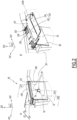
Fig 2] figure 2 represents respectively, in two inserts a) and b), a perspective of the side panel offigure 1 , with the armrest represented in a first configuration and in a second configuration; - [
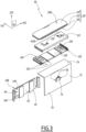
Fig 3] figure 3 is a partially exploded perspective of the armrest offigure 1 ; - [
Fig 4] figure 4 represents respectively, on three inserts a), b) and c), a transversal cross-section of the armrest offigure 2 a) observed along plan IVa onfigure 2 , a detail of a cross section along plan IVb onfigure 2 of the armrest in a third configuration and the detail of insert b) in the first configuration; - [
Fig 5] figure 5 is a perspective view of the armrest offigure 1 , observed from an opposite direction and shown in a fourth configuration, - [
Fig 6] figure 6 is a transversal cross section of the armrest offigure 1 along a plan VI onfigure 2 , and - [
Fig 7] figure 7 is a cross section of the armrest offigure 1 along plan VII onfigure 5 , and - [
Fig 8] figure 8 represents respectively, in two inserts a) and b), a partially exploded perspective of the armrest offigure 1 , with the armrest represented in the first configuration and in the second configuration. - A
vehicle 10 is shown onfigure 1 . Thevehicle 10 is here a road vehicle, in particular a truck. Alternatively, thevehicle 10 is a bus or a railroad vehicle, or even a ship or an aircraft. Thevehicle 10 comprises abody 12, which is usually made out of metal. Thebody 12 comprises afloor 13A, aceiling 13B and side walls, that link thefloor 13A to theceiling 13B. The side walls delimit an interior compartment V10 of thevehicle 10.Figure 1 is a section of thevehicle 10 along a longitudinal plane P10 of the vehicle, and therefore only oneside wall 14 is visible. - A
seat 16 is arranged within the compartment V10, where a user may take place. In the scope of the present description, a "user" is a person seated in aseat 16 of thevehicle 10, for example a driver or a passenger of thevehicle 10. In the illustrated example, the compartment V10 is a front cabin of a truck, and theseat 16 is a driving seat, whose outline is represented in mixed line and which is represented transparent. Theside wall 14 is therefore seen through theseat 16. In a not shown alternative, the interior compartment V10 is a passenger compartment, with one or more seats arranged within the compartment V10. - The
vehicle 10 comprises afront window 18 that is oriented toward a front direction X10 of thevehicle 10. By extension, a longitudinal axis of thevehicle 10 is also referenced X10. In the illustrated example, thevehicle 10 is supposed to rest on a horizontal ground. The longitudinal axis X10 is therefore supposed to be horizontal. The description is given in relation to the orientation of the various elements of thevehicle 10 as represented on the figures, knowing that in reality these various elements may be oriented differently. - The longitudinal plane P10 is a vertical plane. A height axis Z10 of the
vehicle 10 is an axis that is orthogonal to the longitudinal axis X10 and borne by the longitudinal plane P10. The height axis Z10 is here a vertical axis. A transverse axis Y10 of thevehicle 10 is an axis that is orthogonal to both the longitudinal axis X10 and to the height axis Z10, so that the longitudinal axis X10, transverse axis Y10 and height axis Z10 form together a direct coordinate system. The transverse axis Y10 is here horizontal. - When a user takes place on the
seat 16, theside wall 14 is arranged on the left side of the user, and by extension on the left side of theseat 16. The following description is done in relation to the orientation of theside wall 14 as illustrated, knowing that what is valid for theside wall 14 can be transposed to a side wall arranged on the right side of a seat. - Inside the compartment V10, the
side wall 14 is covered by aside panel 20, to provide comfort and safety to the user. Theside panel 20 is partially shown onfigure 2 . When attached to theside wall 14, theside panel 20 extends globally parallel to theside wall 14, i.e. parallel to the longitudinal plane P10. - The
side panel 20 comprises a protruding volume that provides an arm-restingarea 22 to a user of thevehicle 10. The arm-restingarea 22 is sensibly oriented upwards, i.e. orthogonal to the height axis Z10. - In the illustrated example, the arm-resting
area 22 comprises a fixedportion 24, which is immobile relative to theside wall 14, andmobile portion 26, which can be adjusted in height relative to the rest of theside panel 20, i.e. along the height axis Z10, by a user. Themobile portion 26 is part of anadjustable armrest 50, also simply calledarmrest 50. Alternatively, the arm-restingarea 22 does not comprise any fixed portion, and only the armrest 50 forms the arm-restingarea 22. - The
armrest 50 is described with reference tofigures 2 to 7 . Onfigure 2 , thearmrest 50 is represented in a raised configuration, where themobile portion 26 of the restingarea 22 is raised, along the height axis Z10, relative to the fixedportion 24. When themobile portion 26 is aligned with the fixedportion 24, thearmrest 50 is in a low configuration. - The
armrest 50 comprises abracket 60, which is configured to be fixed onto theside panel 20, and asupport portion 70, which is adjustable in height relative to thebracket 60. - The
bracket 60, which is more particularly visible onfigures 3 and4 , comprises amain wall 62, which extends parallel to theside panel 20 when thebracket 20 is attached to thisside panel 20, i.e. parallel to the longitudinal plane P10. Themain wall 62 comprises aninner side 63A, oriented toward the interior compartment V10, and anouter side 63B, opposite to theinner side 63A, i.e. oriented toward theside wall 14 when in use. - The
bracket 60 comprises asecondary wall 64, which extends parallel to themain wall 62 and faces theinner side 63A of themain wall 62. In the illustrated example, thesecondary wall 64 has a rectangular shape with a longer side extending along the height axis Z10. Thesecondary wall 64 and themain wall 62 are limiting, between themselves, an inner volume V60 of thebracket 60. - The
bracket 60 comprises a notchedportion 66, which is arranged on thesecondary wall 64 and which is oriented toward the inner volume V60 of thebracket 60. The notchedportion 66 comprisesseveral notches 68, which are stacked along the height axis Z10. The In the illustrated example, eachnotch 68 extend parallel to the longitudinal axis X10. - The
support portion 70 comprises anouter wall 72, which comprises anouter face 73A, configured to be oriented toward the interior compartment V10 of thevehicle 10, and aninner face 73B, opposite to theouter face 73A. When the armrest 50 is assembled, theouter wall 72 extends parallel to themain wall 62, with theinner face 73A of the outer wall 73 facing theinner side 63A of themain wall 62. Thesecondary wall 64 is arranged between themain wall 62 and theouter wall 72. - The
support portion 70 also comprises anupper wall 74. In the illustrated example, theouter wall 72 and theupper wall 74 are made in one piece, for example produced by hot injection of polymer material. Theupper wall 74 extends orthogonally to theouter wall 72, i.e. orthogonally to the height axis Z10. - The
support portion 70 comprises aflexible zone 76, which is arranged on theouter wall 72. Theflexible zone 76 is accessible by a user when seating in theseat 16. In the illustrated example, theflexible zone 76 has a rectangular shape and is delimited by three cut-outs that form three sides offlexible zone 76, including an upper cut-out 78A, that extends parallel to the longitudinal axis X10, and two side cut-outs 78B, that extends parallel to the height axis Z10. - When the
flexible zone 76 is subject to no external force, the flexible zone is in a relaxed configuration, as illustrated on the figures. Preferably, in the relaxed configuration theflexible zone 76 is flush with the rest of theouter wall 72. When a user exerts a force on theflexible zone 76 on theouter face 73A, in other words when a user pushes theflexible zone 76, theflexible zone 76 deforms elastically and passes to a deformed configuration. When the user stops pushing theflexible zone 76, theflexible zone 76 tends to elastically return to its relaxed configuration. - In the deformed configuration, the
flexible zone 76 is moved closer to themain wall 62 and the upper cut-out 78A provides agripping element 80 to a user. As explained hereinafter, the grippingelement 80 is configured for a user to lift thesupport portion 70 along the height axis Z10. - The
support portion 70 comprises a teethedportion 82, which is linked to theflexible zone 76 by linkingmembers 84, as illustrated onfigure 4 a) . The movements of the teethedportion 82 along the transverse axis Y10 are therefore controlled by the movements of theflexible zone 76. Theouter wall 72, the teethedportion 82 and thelinks 84 are preferably manufactured in one piece, for example by hot injection of synthetic polymer. - A part of the teethed
portion 82 extends along the longitudinal axis X10 and is received in the inner volume V60 of thebracket 60 The teethedportion 82 comprisesteeth 86, which extend along the longitudinal axis X10 and which are configured to cooperate, by shape complementarity, with thenotches 68 of the notchedportion 66, so that translation movements of thesupport portion 70 relative to thebracket 60 along the height axis Z10 are prevented. - When the
flexible zone 76 is in the relaxed configuration, the teethedportion 82 cooperates with the notchedportion 66. The teethedportion 82 is then said to be in an engaged configuration, visible on the inserts b) and c) offigure 4 . When theflexible zone 76 is in the deformed configuration, the teethedportion 82 does not cooperate with the notchedportion 66 and does not prevent translation movements of thesupport portion 70 relative to thebracket 60 along the height axis Z10. The teethedportion 82 is then said to be in a disengaged configuration. - The shape, number and arrangement of the
teeth 84 andnotches 68 is not limitative. In an alternative not shown, the teethedportion 82 comprises only one tooth. More generally, the teethedportion 82 forms a complementary organ configured to cooperate with the notchedportion 66. The complementary organ is configured to pass from the engaged configuration, where the complementary organ cooperates with the notchedportion 66 and prevents height adjustment movements of thesupport portion 70 relative to thebracket 60, to a disengaged configuration, where the complementary organ does not cooperates with the notchedportion 66 and does not prevent height adjustment movements of thesupport portion 70 relative to thebracket 60. - The teethed
portion 82, moved by theflexible zone 76, and thetoothed portion 66 form together amechanism 90, configured to adjust in position thesupport portion 70 relatively to thebracket 60 along the height axis Z10. To adjust the height of thesupport portion 70, a user has simply to push theflexible zone 76 in the deformed configuration, freeing theteeth 86 from thenotches 68. The teethedportion 82 is then in the disengaged configuration. - Then, the user may lift the
support portion 70 by exerting an upward force on thegripping element 80. Alternatively, the user by lower thesupport portion 70 by exerting a downward force on thegripping element 80 or on themobile portion 26 of the arm-restingarea 22. - Once the
support portion 70 reaches the desired height, the user stops his effort on theflexible zone 76, which returns elastically to its relaxed configuration. At the same time, the teethedportion 82 returns to its engaged configuration, locking the position of thesupport portion 70. Thismechanism 90 is very simple - and therefore cheap - to manufacture and easy to operate, since the user may push theflexible zone 76 by hand and without any tool. - According to another aspect of the invention, the
mobile portion 26 of the arm-restingarea 22 may also be adjusted in position along the transverse axis Y10. - To this end, the armrest 50 further comprises a guiding
board 100, which is borne by theupper wall 74 and which comprises lateral guides 102. The lateral guides 102 are arranged along the transverse axis Y10. In other words, the lateral guides 102 are borne by theupper wall 74. - The guiding
board 100 also comprisessecondary notches 104. Thesecondary notches 104 are facing upwards, eachsecondary notches 104 extending parallel to each other and orthogonally to the lateral axis Y10, thesecondary notches 104 being stacked along the transverse axis Y10. A section of thesecondary notches 104 is visible onfigure 6 . In the illustrated example, the guidingboard 100 comprises threesecondary notches 104. The shape and numbers of thesecondary notches 104 are not limitative. - The armrest 50 also comprises a sliding
board 110, which cooperates with the lateral guides 102 so that the only possible movements of the slidingboard 110 relative to the guidingboard 100 are translation movement along the transverse axis Y10. - The sliding
board 110 comprises a teethedorgan 112, configured to cooperate with thesecondary notches 104. In the illustrated example, the teethedorgan 112 comprises asecondary teeth 114 arranged at the extremity of aflexible tab 116. Thesecondary teeth 114 is oriented downwards and is configured to cooperate, by shape complementarity, with thesecondary notches 104. When no external force is exerted on the teethedorgan 112, the teethedorgan 112 is in a relaxed configuration, where thesecondary teeth 114 cooperate with thesecondary notches 104 and prevents translation movements of the slidingboard 110 relative to the guidingboard 100 along the transverse axis Y10. In other words, lateral adjustment of the slidingboard 110 is prevented. - When a user exerts an upward force on the
secondary teeth 114, the teethedorgan 112 is in a constrained configuration, where theflexible tab 116 deforms elastically and thesecondary teeth 114 do not cooperate with thesecondary notches 104. In other words, the translation movements of the slidingboard 110 relative to the guidingboard 100 along the transverse axis Y10 are allowed. The user may then move the lateral position of the slidingboard 110 relative to the guiding board to the position of his choice. - When the user stops exerting an upward force on the secondary teeth, the teethed
organ 112 returns elastically to its relaxed configuration. In other words, lateral adjustment movements of the sliding board are prevented. - The teethed
organ 112 and thesecondary notches 104 form together a secondary mechanism, configured to adjust in position the slidingboard 110 relative to the guiding portion 100 - and by extension to the upper wall 74 - along the transverse axis Y10. - The guiding
board 110 comprises anupper wall 118, which extends parallel to theflexible tab 116 and which comprises guidinggrooves 120. Each guidinggroove 120 extends along a path and has two extremities, with a startingextremity 122A and an endingextremity 122B. The guidinggrooves 120 have the same shape. - As illustrated on
figure 7 , the guidinggrooves 120 extend here along a path that is L-shaped, with a portion parallel to the transverse axis Y10 and a portion parallel to the longitudinal axis X10. Other shapes are possible for the guidinggrooves 120. - The armrest 50 also comprises a
tray 130. Thetray 130 comprises alower board 132, anupper board 134 and ahinge 136 that links theupper board 134 to thelower board 132. In other words. Thehinge 136 extends along a hinge axis A136, which is parallel to the longitudinal axis X10. In other words, theupper board 134 is hinged with thelower board 132 along the hinge axis A136, while thetray 130 is a foldable tray. - The
tray 130 is switchable, by a user, between a folded configuration, where theupper board 134 is folded onto thelower board 132 and forms themobile portion 26 of the arm-restingarea 22, and an unfolded configuration, where theupper board 134 extends next to and parallel to thelower board 132, the upper and lower boards forming together a tray for the user. - On
figure 5 , thetray 130 is represented in an intermediate configuration, between the folded and the unfolded configuration. Thelower board 132 has atop side 133A, which is oriented upwards when thearmrest 50 is assembled, and adown side 133B, which is opposed to thetop side 133A, i.e. oriented downwards. Theupper board 134 has atop side 135A, which is oriented upwards when thetray 130 is in the folded configuration, and adown side 135B, which is opposed to thetop side 135A of theupper board 134, i.e. oriented downwards when thetray 130 is in the folded configuration. - When the
tray 130 is in the unfolded configuration, the orientation of theupper board 134 is reversed, i.e. thetop side 135A is oriented downwards, while thedown side 135A of theupper board 134 is oriented upwards. Preferably, in the unfolded configuration of thetray 130 thetop side 133A of the underboard 132 and thedown side 135B of theupper board 134 are borne by a geometric plane that is orthogonal to the height axis Z10, so as to provide a flat tray surface to the user. - Preferably, the
upper board 134 comprises a layer made of soft material, for example a cushionedlayer 138, which covers theupper side 135A of theupper board 134. Advantageously, thetop surface 133A of thelower board 132 and thedown surface 135B of theupper board 134 compriseslots 140, which face each other in the folded configuration and which are configured to receive magnets, configured to maintain thetray 130 in the folded configuration. The magnets are not represented. - The
tray 130 also comprisespins 142, which are arranged on thedown side 133B of thelower tray 132 and which are configured to cooperate, by shape complementarity, with the guidinggrooves 120, so that thepins 142 are configured to travel, under the action of a user, within the guidinggrooves 120. In other words, movements of thetray 130 relative to the slidingboard 110 are determined by the shape of thegrooves 120, which receive thepins 142. Thepins 142 and thegroove 120 give the user an additional possibility of position adjustment, in addition to the position adjustments previously described, along the height axis Z10 or along the transverse axis Y10. - Advantageously,
protrusions 123 are arranged within each guidinggroove 120, theprotrusions 123 being configured to prevent movements of thepins 142 within thegrooves 120 when thepins 142 are in a starting position, where thepins 142 are in contact with the startingextremity 122A. When the user moves the tray along the guidinggrooves 120, theprotrusions 123 are deformed elastically to accommodate the passage of thepins 142. - The armrest 50 also comprises two
stabilizers 150, which are visible onfigures 5 ,7 and8 . Thestabilizers 150 are arranged on each side of thesupport portion 70 along the longitudinal axis X10. Thestabilizers 150 are configured to stabilizesupport portion 70 when thesupport portion 70 is adjusted in position relative to thebracket 60 along the height axis Z10. In particular, thestabilizers 150 are configured to prevent the translation movements of thesupport portion 70 relative to thebracket 60 along the longitudinal axis X10. - The two
stabilizers 150 are preferably identical to each other. Thestabilizer 150 shown onfigure 8 is now described. - The
stabilizer 150 comprises arail 152, which extends along the transverse axis Y10 and which has here an Omega-shaped section. When the armrest 50 is assembled to theside panel 20, therail 152 is fixed to theside panel 20. Anoblong hole 154 that extends along the transverse axis Y20 is arranged in a central portion of therail 152, while anaxis hole 156 is arranged at an extremity of the central portion of therail 152. - The stabilizer also comprises a
main rod 160, which comprises afirst end 162 with afirst stud 164 received in theaxis hole 156, so that themain rod 160 is able to rotate relative to therail 152 along a rotation axis parallel to the longitudinal axis X10. Themain rod 160 also comprises asecond end 166, which is opposite to thefirst end 162 and which comprises asecond stud 168, which extends parallel to thefirst stud 164 and which is arranged on an opposite side to thefirst stud 164 relative to themain rod 160. A slidingroller 170 is arranged on thesecond stud 168. The slidingroller 170 is received in aslide groove 172, which is arranged on thesupport portion 70 along the transverse axis Y20. In the illustrated example, theslide groove 172 has a rectangular section and is arranged on the slidingboard 100. - The
main rod 160 also comprises acentral hole 174, which is arranged in a middle portion of themain road 160 between thefirst end 162 and thesecond end 166, preferably in the middle of themain rod 160. Thecentral hole 174 is centered along an axis A176 parallel to the longitudinal axis X10. - The
stabilizer 150 also comprises asecond rod 180, with afirst extremity 182 comprising afirst stud 184 received in thecentral hole 174, so that thesecond rod 180 is mobile in rotation relative to themain rod 160 along the axis A176 of thecentral hole 174. Thesecond rod 180 comprises asecond extremity 184, which is opposite to thefirst extremity 182 and which comprises asecond stud 188 that is received slidingly in theoblong hole 154. Anut 190 is fitted to thesecond stud 188 so that thesecond stud 188 is captured in theoblong hole 154. - When the height of the bearing
portion 70 is adjusted relative to thebracket 60, the slidinggroove 172 drags the slidingroller 170, which slides within the slidinggroove 172. As themain rod 160 rotates relative to therail 152, themain rod 160 also drags thesecond rod 180 by itsfirst extremity 182, while thesecond stud 188 of thesecond extremity 186 of thesecond rod 180 slides along theoblong hole 154. - In the illustrated example, the lateral guides are arranged in the guiding board, which is distinct from and assembled to the upper wall, for example by using fixing elements such as screws or by welting or gluing. Alternatively, the guiding board and the upper wall are manufactured in one piece. In both case, the lateral guides are borne by the upper wall.
- In the illustrated example, the notched portion is arranged on the bracket, while the teethed portion is arranged on the support portion.
- In a not shown alternative, a mirror arrangement is selected, with the notched portion arranged on the support portion, while the teethed portion is arranged on the bracket. In any case, the flexible zone remains accessible to the user from the interior compartment V10.
- The respective features of the different embodiments and variants of the device considered in this description can be combined to create new embodiments, within the scope of the appended claims.
Claims (10)
- An armrest (50) for a side panel (20) of a vehicle (10), especially a road vehicle, the armrest (50) comprising:- a bracket (60), comprising a main wall (62) configured to be fixed onto the side panel (20),- a support portion (70) comprising:• an outer wall (72), which extends parallel to the main wall (62) and which comprises an outer face (73A), oriented toward an interior compartment (V10) of the vehicle (10), and• an upper wall (74), which extends orthogonally to a height axis (Z10) of the vehicle and which is configured to provide an arm-resting (26) area to a user of the vehicle,- a mechanism, configured to adjust in height the support portion (70) relatively to the bracket (60) along the height axis (Z10),characterized in that:- the mechanism comprises a notched portion (66), which is arranged on one element among the bracket (60) and the support portion (70) and which comprises notches (68), which are stacked along the height axis (Z10),- the notched portion (66) is configured to cooperate with a complementary organ (82), for example a teethed portion, which is arranged on the other element among the bracket (60) and the support portion (70),- the complementary organ (82) is configured to pass from an engaged configuration, where the complementary organ (82) cooperates with the notched portion (66) and prevents height adjustment movements of the support portion (70) relative to the bracket (60), to a disengaged configuration, where the complementary organ (82) does not cooperates with the notched portion (66) and does not prevent height adjustment movements of the support portion (70) relative to the bracket (60), and- the adjustment mechanism comprises a flexible zone (76), arranged either on the bracket (60) or on the support portion (70), the flexible zone (76) being configured to switch between a relaxed configuration, where the complementary organ (82) is in the engaged configuration, and a deformed configuration, where the complementary organ (82) is moved in the disengaged configuration, and- the flexible zone (76) is configured to pass from the relaxed configuration to the deformed configuration by elastic deformation under the action of an user, by hand and without any tool, whereas the flexible zone (76) tends to elastically return to its relaxed configuration.
- The armrest (50) according to claim 1, wherein:- the notched portion (66) is arranged on the bracket (60),- the complementary organ (82) is arranged on the support portion (70),- the flexible zone (76) is arranged on the outer wall (72) and is configured to provide a gripping element (80) when the flexible zone (76) is in the deformed configuration, the gripping element (80) being configured for a user to lift the support portion (70) along the height axis (Z10).
- The armrest (50) according to claim 2, wherein- the bracket (60) comprises a secondary wall (64), which extends parallel to the main wall (62) between the outer wall (72) and the main wall (62), the secondary wall (64) and the main wall (62) limiting between themselves an inner volume (V60) of the bracket (60),- the notched portion (66) is arranged on the secondary wall (64) and is oriented toward the inner volume (V60) of the bracket (60),- the complementary organ is a teethed portion (82), which is received in the inner volume (V60) of the bracket (60).
- The armrest (50) according to any one of claims 1 to 3, wherein the support portion (70) further comprises:- lateral guides (102), which are borne by the upper wall (74) and which arranged along a transverse axis orthogonal to the outer wall (72),- a sliding board (110), which cooperates with the lateral guides (102) and which is mobile in translation relatively to the support portion (70) along a transverse axis (Y10), which is orthogonal to the outer wall (72), and- a secondary mechanism, configured to adjust in position the sliding board (110) relative to the upper wall (74) along the transverse axis (Y10), in a lateral adjustment movement,wherein:- the secondary mechanism comprises:• secondary notches (104), which are borne by the upper wall (74) and which are facing upwards, each secondary notches (104) extending parallel to each other and orthogonally to the transverse axis (Y10), the secondary notches (104) being stacked along the transverse axis (Y10),• a teethed organ (112), which is arranged on the sliding board (110), the teethed organ (112) having a secondary teeth (114) being oriented downwards and being configured to cooperate with the secondary notches (104),- the teethed organ (112) is elastically deformable, by a user, between a relaxed configuration and a constrained configuration, the teethed organ (112) being configured to elastically return to its relaxed configuration,- when the teethed organ (112) is in the relaxed configuration; the teethed organ (112) cooperates with the secondary notches (104) so that lateral adjustment movements of the sliding board (110) are prevented,- when the teethed organ (112) is in the constrained configuration, the teethed organ (112) does not cooperate with the secondary notches (104) and lateral adjustment movements of the sliding board (110) are possible.
- The armrest (50) according to any one of claims 1 to 4, wherein:- the support portion (70) comprises a foldable tray (130), with a lower board (132) and an upper board (134), which is hinged with the lower board (132) along a hinge axis (A136) that is parallel to a longitudinal axis (X10) of the vehicle (10),- the lower board is borne by and parallel to the upper wall (74),- the tray (130) is switchable, by a user, between a folded configuration, where the upper board (134) is folded onto the lower board (132) and forms an arm-resting area (26) for the user, and an unfolded configuration, where the upper board (134) extends next to the lower board (132), the upper and lower boards forming together a tray for the user.
- The armrest (50) according to claim 5, wherein:- the foldable tray (130) comprises pins (142), which are arranged on an under side (133B) of the lower board (132),- the support portion (70) comprises guiding grooves (120), which receive the pins (142), the pins being configured to travel within the guiding grooves (120) under the action of a user.
- The armrest (50) according to claim 6, wherein the guiding grooves (120) are L-shaped, with a portion arranged parallel to the transverse axis (Y10) and a portion arranged parallel to the longitudinal axis (X10).
- The armrest (50) according to any one of claims 1 to 7, wherein the armrest also comprises two stabilizers (150), which are arranged on both sides of the armrest and which are configured to prevent translation movements of the bearing portion (70) relative to the bracket (60) along the longitudinal axis (X10).
- A side panel (20) of a vehicle (10), comprising an armrest (50) according to any one of claims 1 to 8.
- A vehicle (10), comprising a body (12) with side walls (14) that delimit an interior compartment (V10) of the vehicle, wherein at least one of the side walls (14) is covered by a side panel (20) according to claim 9.
Priority Applications (1)
| Application Number | Priority Date | Filing Date | Title |
|---|---|---|---|
| EP22179269.0A EP4292878B1 (en) | 2022-06-15 | 2022-06-15 | Armrest for a vehicle, associated side panel and vehicle |
Applications Claiming Priority (1)
| Application Number | Priority Date | Filing Date | Title |
|---|---|---|---|
| EP22179269.0A EP4292878B1 (en) | 2022-06-15 | 2022-06-15 | Armrest for a vehicle, associated side panel and vehicle |
Publications (2)
| Publication Number | Publication Date |
|---|---|
| EP4292878A1 true EP4292878A1 (en) | 2023-12-20 |
| EP4292878B1 EP4292878B1 (en) | 2025-12-03 |
Family
ID=82067435
Family Applications (1)
| Application Number | Title | Priority Date | Filing Date |
|---|---|---|---|
| EP22179269.0A Active EP4292878B1 (en) | 2022-06-15 | 2022-06-15 | Armrest for a vehicle, associated side panel and vehicle |
Country Status (1)
| Country | Link |
|---|---|
| EP (1) | EP4292878B1 (en) |
Citations (5)
| Publication number | Priority date | Publication date | Assignee | Title |
|---|---|---|---|---|
| DE4122188A1 (en) * | 1991-07-04 | 1993-01-14 | Kamei Gmbh & Co Kg | Folding table in chair arm rest with vertical holder frame - has two part fitment, with slot, stop-piece, locking-plate, protuberances, and spring |
| DE4135279A1 (en) | 1991-10-25 | 1993-04-29 | Bayerische Motoren Werke Ag | Adjustable armrest for door of vehicle - has drive and guides which allow width of armrest to be extended |
| ES2157738A1 (en) * | 1998-07-30 | 2001-08-16 | Antonio Flores Associats S L | Height regulation device for chair armrests. |
| US20160213153A1 (en) * | 2015-01-28 | 2016-07-28 | Theodore Aubrey Hasson | Portable seat organizer |
| DE102019130142A1 (en) * | 2019-11-08 | 2021-05-12 | Bayerische Motoren Werke Aktiengesellschaft | Center console for a motor vehicle and motor vehicle |
-
2022
- 2022-06-15 EP EP22179269.0A patent/EP4292878B1/en active Active
Patent Citations (5)
| Publication number | Priority date | Publication date | Assignee | Title |
|---|---|---|---|---|
| DE4122188A1 (en) * | 1991-07-04 | 1993-01-14 | Kamei Gmbh & Co Kg | Folding table in chair arm rest with vertical holder frame - has two part fitment, with slot, stop-piece, locking-plate, protuberances, and spring |
| DE4135279A1 (en) | 1991-10-25 | 1993-04-29 | Bayerische Motoren Werke Ag | Adjustable armrest for door of vehicle - has drive and guides which allow width of armrest to be extended |
| ES2157738A1 (en) * | 1998-07-30 | 2001-08-16 | Antonio Flores Associats S L | Height regulation device for chair armrests. |
| US20160213153A1 (en) * | 2015-01-28 | 2016-07-28 | Theodore Aubrey Hasson | Portable seat organizer |
| DE102019130142A1 (en) * | 2019-11-08 | 2021-05-12 | Bayerische Motoren Werke Aktiengesellschaft | Center console for a motor vehicle and motor vehicle |
Also Published As
| Publication number | Publication date |
|---|---|
| EP4292878B1 (en) | 2025-12-03 |
Similar Documents
| Publication | Publication Date | Title |
|---|---|---|
| US6003927A (en) | Center console having lengthwise, laterally and vertically moveable armrest for an automobile | |
| KR100442762B1 (en) | A vehicle seat provided with a f0ld-down back | |
| US9481276B2 (en) | Operable armrest assembly for vehicle door and center console | |
| KR20080091262A (en) | Sheet | |
| KR101861543B1 (en) | Adjustment mechanism for a head restraint | |
| CN105270215B (en) | Vertically adjustable vehicle seat back | |
| EP4292878B1 (en) | Armrest for a vehicle, associated side panel and vehicle | |
| GB2143124A (en) | Adjustable vehicle seat | |
| EP3626524A1 (en) | Armrest and seat arrangement for a vehicle | |
| KR100490585B1 (en) | Center console armrest device | |
| WO2008093918A1 (en) | Apparatus for locking seat track for vehicle | |
| KR102201315B1 (en) | Rear seat frame for SUV vehicle | |
| KR20030074365A (en) | Seat of vehicle equipped mechanical link | |
| CN118219994A (en) | Vehicle console assembly | |
| EP2862745B1 (en) | Mass transit passenger vehicle seat and mass transit passenger vehicle comprising such a seat | |
| JPH05301560A (en) | Through-guide structure for seat belt | |
| JP2006218882A (en) | Automobile seat position adjustment device | |
| DE102023002705B3 (en) | Seat for a rear area of a motor vehicle and method for operating a seat | |
| CN222891925U (en) | Rear seat headrest and vehicle | |
| KR100196165B1 (en) | Seat arm rest height adjustment | |
| KR101143788B1 (en) | A rumber support of vehicles seet | |
| KR20110004604A (en) | Shifter of car table | |
| EP3699024B1 (en) | Seat for a vehicle | |
| KR200199629Y1 (en) | Console box with the function of an armrest | |
| JPH0350780Y2 (en) |
Legal Events
| Date | Code | Title | Description |
|---|---|---|---|
| PUAI | Public reference made under article 153(3) epc to a published international application that has entered the european phase |
Free format text: ORIGINAL CODE: 0009012 |
|
| STAA | Information on the status of an ep patent application or granted ep patent |
Free format text: STATUS: THE APPLICATION HAS BEEN PUBLISHED |
|
| AK | Designated contracting states |
Kind code of ref document: A1 Designated state(s): AL AT BE BG CH CY CZ DE DK EE ES FI FR GB GR HR HU IE IS IT LI LT LU LV MC MK MT NL NO PL PT RO RS SE SI SK SM TR |
|
| STAA | Information on the status of an ep patent application or granted ep patent |
Free format text: STATUS: REQUEST FOR EXAMINATION WAS MADE |
|
| 17P | Request for examination filed |
Effective date: 20240603 |
|
| RBV | Designated contracting states (corrected) |
Designated state(s): AL AT BE BG CH CY CZ DE DK EE ES FI FR GB GR HR HU IE IS IT LI LT LU LV MC MK MT NL NO PL PT RO RS SE SI SK SM TR |
|
| GRAP | Despatch of communication of intention to grant a patent |
Free format text: ORIGINAL CODE: EPIDOSNIGR1 |
|
| STAA | Information on the status of an ep patent application or granted ep patent |
Free format text: STATUS: GRANT OF PATENT IS INTENDED |
|
| INTG | Intention to grant announced |
Effective date: 20250626 |
|
| GRAS | Grant fee paid |
Free format text: ORIGINAL CODE: EPIDOSNIGR3 |
|
| GRAA | (expected) grant |
Free format text: ORIGINAL CODE: 0009210 |
|
| STAA | Information on the status of an ep patent application or granted ep patent |
Free format text: STATUS: THE PATENT HAS BEEN GRANTED |
|
| AK | Designated contracting states |
Kind code of ref document: B1 Designated state(s): AL AT BE BG CH CY CZ DE DK EE ES FI FR GB GR HR HU IE IS IT LI LT LU LV MC MK MT NL NO PL PT RO RS SE SI SK SM TR |
|
| REG | Reference to a national code |
Ref country code: CH Ref legal event code: F10 Free format text: ST27 STATUS EVENT CODE: U-0-0-F10-F00 (AS PROVIDED BY THE NATIONAL OFFICE) Effective date: 20251203 Ref country code: GB Ref legal event code: FG4D |
|
| REG | Reference to a national code |
Ref country code: DE Ref legal event code: R096 Ref document number: 602022025982 Country of ref document: DE |
|
| REG | Reference to a national code |
Ref country code: IE Ref legal event code: FG4D |
|
| REG | Reference to a national code |
Ref country code: NL Ref legal event code: MP Effective date: 20251203 |
|
| PG25 | Lapsed in a contracting state [announced via postgrant information from national office to epo] |
Ref country code: ES Free format text: LAPSE BECAUSE OF FAILURE TO SUBMIT A TRANSLATION OF THE DESCRIPTION OR TO PAY THE FEE WITHIN THE PRESCRIBED TIME-LIMIT Effective date: 20251203 |
|
| REG | Reference to a national code |
Ref country code: LT Ref legal event code: MG9D |
|
| PG25 | Lapsed in a contracting state [announced via postgrant information from national office to epo] |
Ref country code: NO Free format text: LAPSE BECAUSE OF FAILURE TO SUBMIT A TRANSLATION OF THE DESCRIPTION OR TO PAY THE FEE WITHIN THE PRESCRIBED TIME-LIMIT Effective date: 20260303 |
|
| PG25 | Lapsed in a contracting state [announced via postgrant information from national office to epo] |
Ref country code: FI Free format text: LAPSE BECAUSE OF FAILURE TO SUBMIT A TRANSLATION OF THE DESCRIPTION OR TO PAY THE FEE WITHIN THE PRESCRIBED TIME-LIMIT Effective date: 20251203 Ref country code: HR Free format text: LAPSE BECAUSE OF FAILURE TO SUBMIT A TRANSLATION OF THE DESCRIPTION OR TO PAY THE FEE WITHIN THE PRESCRIBED TIME-LIMIT Effective date: 20251203 |
|
| PG25 | Lapsed in a contracting state [announced via postgrant information from national office to epo] |
Ref country code: RS Free format text: LAPSE BECAUSE OF FAILURE TO SUBMIT A TRANSLATION OF THE DESCRIPTION OR TO PAY THE FEE WITHIN THE PRESCRIBED TIME-LIMIT Effective date: 20260303 |
|
| PG25 | Lapsed in a contracting state [announced via postgrant information from national office to epo] |
Ref country code: PL Free format text: LAPSE BECAUSE OF FAILURE TO SUBMIT A TRANSLATION OF THE DESCRIPTION OR TO PAY THE FEE WITHIN THE PRESCRIBED TIME-LIMIT Effective date: 20251203 |
|
| PG25 | Lapsed in a contracting state [announced via postgrant information from national office to epo] |
Ref country code: LV Free format text: LAPSE BECAUSE OF FAILURE TO SUBMIT A TRANSLATION OF THE DESCRIPTION OR TO PAY THE FEE WITHIN THE PRESCRIBED TIME-LIMIT Effective date: 20251203 |
|
| PG25 | Lapsed in a contracting state [announced via postgrant information from national office to epo] |
Ref country code: BG Free format text: LAPSE BECAUSE OF FAILURE TO SUBMIT A TRANSLATION OF THE DESCRIPTION OR TO PAY THE FEE WITHIN THE PRESCRIBED TIME-LIMIT Effective date: 20251203 |