EP4292191B1 - Charger - Google Patents
Charger Download PDFInfo
- Publication number
- EP4292191B1 EP4292191B1 EP22704605.9A EP22704605A EP4292191B1 EP 4292191 B1 EP4292191 B1 EP 4292191B1 EP 22704605 A EP22704605 A EP 22704605A EP 4292191 B1 EP4292191 B1 EP 4292191B1
- Authority
- EP
- European Patent Office
- Prior art keywords
- charger
- fan
- compartment
- charging
- battery pack
- Prior art date
- Legal status (The legal status is an assumption and is not a legal conclusion. Google has not performed a legal analysis and makes no representation as to the accuracy of the status listed.)
- Active
Links
Images

Classifications
-
- H—ELECTRICITY
- H02—GENERATION; CONVERSION OR DISTRIBUTION OF ELECTRIC POWER
- H02J—ELECTRIC POWER NETWORKS; CIRCUIT ARRANGEMENTS OR SYSTEMS FOR SUPPLYING OR DISTRIBUTING ELECTRIC POWER; SYSTEMS FOR STORING ELECTRIC ENERGY
- H02J7/00—Circuit arrangements for charging or discharging batteries or for supplying loads from batteries
- H02J7/70—Circuit arrangements for charging or discharging batteries or for supplying loads from batteries characterised by the mechanical construction
-
- H—ELECTRICITY
- H02—GENERATION; CONVERSION OR DISTRIBUTION OF ELECTRIC POWER
- H02J—ELECTRIC POWER NETWORKS; CIRCUIT ARRANGEMENTS OR SYSTEMS FOR SUPPLYING OR DISTRIBUTING ELECTRIC POWER; SYSTEMS FOR STORING ELECTRIC ENERGY
- H02J7/00—Circuit arrangements for charging or discharging batteries or for supplying loads from batteries
- H02J7/70—Circuit arrangements for charging or discharging batteries or for supplying loads from batteries characterised by the mechanical construction
- H02J7/751—Circuit arrangements for charging or discharging batteries or for supplying loads from batteries characterised by the mechanical construction concerning the insertion or the connection of the batteries
-
- H—ELECTRICITY
- H05—ELECTRIC TECHNIQUES NOT OTHERWISE PROVIDED FOR
- H05K—PRINTED CIRCUITS; CASINGS OR CONSTRUCTIONAL DETAILS OF ELECTRIC APPARATUS; MANUFACTURE OF ASSEMBLAGES OF ELECTRICAL COMPONENTS
- H05K7/00—Constructional details common to different types of electric apparatus
- H05K7/20—Modifications to facilitate cooling, ventilating, or heating
- H05K7/2089—Modifications to facilitate cooling, ventilating, or heating for power electronics, e.g. for inverters for controlling motor
- H05K7/20909—Forced ventilation, e.g. on heat dissipaters coupled to components
-
- Y—GENERAL TAGGING OF NEW TECHNOLOGICAL DEVELOPMENTS; GENERAL TAGGING OF CROSS-SECTIONAL TECHNOLOGIES SPANNING OVER SEVERAL SECTIONS OF THE IPC; TECHNICAL SUBJECTS COVERED BY FORMER USPC CROSS-REFERENCE ART COLLECTIONS [XRACs] AND DIGESTS
- Y02—TECHNOLOGIES OR APPLICATIONS FOR MITIGATION OR ADAPTATION AGAINST CLIMATE CHANGE
- Y02E—REDUCTION OF GREENHOUSE GAS [GHG] EMISSIONS, RELATED TO ENERGY GENERATION, TRANSMISSION OR DISTRIBUTION
- Y02E60/00—Enabling technologies; Technologies with a potential or indirect contribution to GHG emissions mitigation
- Y02E60/10—Energy storage using batteries
Definitions
- the present disclosure relates to a charger for a battery-operated system, configured to charge a battery pack, the charger comprising a housing, a charging socket in the housing for receiving a battery pack, and charging electronics configured to provide a direct current to electric connectors associated with the charging socket for charging the battery pack, and a fan arrangement for force cooling the battery pack during charging.
- US 2015/244034 A1 proposes a battery charger with a fan positioned near an opening in a housing of the charger such that the fan may intake air from outside the charger and distribute the air to cool a battery attached to the charger.
- the housing comprises a fan compartment, enclosing the fan, and an electronics compartment, enclosing the charging electronics, wherein the fan compartment and the electronics compartment are separated at least by a wall.
- the fan arrangement is given its own space.
- moist may appear in the charging socket. For instance, if a battery pack has been used outdoors, perhaps in cool or freezing conditions, and is brough indoors for charging, water from the ambient air may form condensation on the battery that drips into the charging socket.
- the fan arrangement in order to be able to force cool the battery pack, needs to connect to the charging socket in some way or the other, but thanks to the wall or the like in between the fan compartment and the electronics department, the charging electronics is shielded from moist in an improved way. This provides better insulation and hence improved safety and reliability.
- the fan compartment comprises an air inlet and an air outlet, and typically the fan compartment air outlet is connected to the charging socket.
- the air inlet and air outlet may be substantially vertically oriented when the charger is placed on a horizontal surface. This protects the inlet and outlet to some extent from e.g. water droplets coming from above.
- the charger comprises a drain in the charging socket which is located lower than the fan compartment air outlet when the charger is placed on a horizontal surface. This prevents any moisture collected in the charging socket from entering the fan compartment.
- the drain may be located in the vicinity of the electric connectors.
- the electronics compartment may be enclosed by a set of walls, and one such wall may be made up of a cooling flange. This enables both a protected, sealed electronics compartment and efficient transfer of heat from that compartment.
- the cooling flange may be made of aluminum and the other walls at least partly of plastic. There may be provided a gasket in between the cooling flange and the other walls.
- the cooling flange may be located in a cooling channel which has its inlet and outlet located on the bottom side of the charger.
- the housing may comprise a fan compartment, enclosing a fan for cooling the battery pack, and the fan compartment and the electronics compartment may be separated at least by a wall.
- the present disclosure relates generally to a charger 1 in a battery-operated system, which charger is configured to charge a battery pack 21, as illustrated with an example in fig 1 .
- Such a system may typically employ two or more such battery packs 21 although this is not necessary.
- one battery pack is used in a tool (not shown), while the other is being charged.
- the present disclosure provides a charger 1 with improved reliability and safety.
- the charger 1 as shown in fig 1 , comprises a housing 3 and a charging socket 5 in the housing for receiving a battery pack 21.
- the charger comprises a power plug 23 adapted to be connected to an AC mains socket (not shown) and internal charging electronics, in an electronics compartment 13, typically a rectifier and various control- and communications circuitry, adapted to convert received AC power and provide a DC charging current to electric connectors 7 in the charging socket 5 for charging the battery pack 21.
- a fan arrangement 9 is provided for force cooling the battery pack 21 during charging.
- the fan arrangement 9 includes a motor and a fan driven by the motor.
- the battery pack 21 may comprise an air inlet and an air outlet as well as a channel extending therebetween in order to provide efficient cooling of cells therein, but it would also be conceivable to provide cooling by means of external cooling flange, with the cooling effect augmented by forced cooling, for instance.
- the present disclosure provides improved safety and reliability of such a charger.
- the charger 1 is normally but not exclusively intended to be used indoors in dry conditions, but this does not always mean that the charger can be kept dry. For instance, if a battery pack 21 has been used outdoors in cold or even freezing conditions, it may be very cold. Using the battery also means that it develops some heat and can be kept warm to some extent. However, a considerable time may have passed since the last use, and the battery pack 21 may be at a temperature even below 0°C when brought indoors for charging. This means that condensation may be formed on the battery before heating up from charging and that condensation may drip into the charging socket 5 of the charger 1. This implies a risk for malfunction of the charging electronics if water would enter in the charging electronics compartment 13.
- this problem is eliminated or reduced by providing the housing 3 with a fan compartment 11.
- This fan compartment 11, which encloses the fan 9, is to some extent separate from an electronics compartment 13 enclosing the charging electronics.
- the fan compartment 11 and the electronics compartment 13 are typically separated at least by a wall 15.
- the fan arrangement 9 typically needs to be in contact with the charging socket 5 to be able to cool the battery pack 21 during charging. This is not the case for the charging electronics, however.
- the fan arrangement 9 itself can have a higher rating with regard to moisture resistance and lead-throughs for driving the fan and connecting to the DC connectors 7 for the battery pack can be arranged in a watertight manner.
- the fan compartment comprises an air inlet 17 and an air outlet 19 to be able to create a flow through the fan compartment, but the fan compartment could also be open in different ways.
- the fan compartment has an air outlet 19 is connected to the charging socket 5, such that efficient feeding of air towards the battery pack is achieved.
- the air inlet 17 receives ambient air.
- the inlet 17 and outlet 19 may be vertically oriented, at least extending in planes deviating less than 10 degrees from vertical when the charger is placed on a horizontal surface such that a too large area is not presented to matter, such as rain or dust, coming from above. This protects the inlet and outlet to some extent from rain coming from above if located outdoors. They could also face slightly downwards.
- a drain 41 is provided in the charging socket 5 to lead away any water therefrom.
- This drain 41 is located lower than the fan compartment air outlet 19, when the charger is placed on a horizontal surface, to prevent any moisture collected in the charging socket from entering the fan compartment 11. It may be preferred to locate this drain 41 in the vicinity of, or even more preferred in between, electric connectors 7 of the charger. This also keeps the electric connectors drier.
- FIG. 1 A cooling arrangement for the charging electronics which is not in direct contact with the charging socket 5.
- FIG. 1 A cooling arrangement for the charging electronics which is not in direct contact with the charging socket 5.
- FIG. 1 A cooling arrangement for the charging electronics which is not in direct contact with the charging socket 5.
- FIG. 1 A cooling arrangement for the charging electronics which is not in direct contact with the charging socket 5.
- FIG. 1 A cooling arrangement for the charging electronics which is not in direct contact with the charging socket 5.
- FIG. 1 A cooling arrangement for the charging electronics which is shown in Fig 2A and 2B illustrating cross sections through the charger of fig 1 .
- This cooling arrangement comprises a fan 31 that feeds ambient air from an inlet 35 in the bottom side of the charger housing 3, via a cooling flange 33, and to an outlet 37 also in the bottom side thereof.
- the charger may rest on feet 39 that project from the bottom side of the housing to provide an open space under the charger housing 3 by elevating the latter to some extent when resting for instance on a tabletop or the like. It is advantageous to locate
- a cooling flange 33 in the air flow path, which may be closely connected with the charger electronics.
- the present disclosure considers providing the electronics compartment 13 as a space defined by a set of walls 33, 41, wherein one such wall is provided by the cooling flange 33.
- the cooling flange 33 is typically made from extruded aluminum while the remainder of the electronics compartment walls may be provided in one or more pieces by injection moulding plastics, for instance.
- a sealing device for instance comprising a silicone rubber gasket 43 may optionally be provided in between the cooling flange and the remainder of the electronics compartment walls, in order to provide a more watertight space.
- the cooling flange 33 is capable of serving the dual purposes of leading out generated heat from the electronics compartment 13 and to seal off the electronics compartment 13. This arrangement functions very well in combination with the separate fan compartment as described above, but the cooling flange serving this dual purpose could also be used in a charger where the battery pack is passively cooled or has its own internal cooling fan, for instance.
Landscapes
- Engineering & Computer Science (AREA)
- Microelectronics & Electronic Packaging (AREA)
- Power Engineering (AREA)
- Physics & Mathematics (AREA)
- Thermal Sciences (AREA)
- Charge And Discharge Circuits For Batteries Or The Like (AREA)
- Secondary Cells (AREA)
- Valve Device For Special Equipments (AREA)
- Eye Examination Apparatus (AREA)
- Steroid Compounds (AREA)
Description
- The present disclosure relates to a charger for a battery-operated system, configured to charge a battery pack, the charger comprising a housing, a charging socket in the housing for receiving a battery pack, and charging electronics configured to provide a direct current to electric connectors associated with the charging socket for charging the battery pack, and a fan arrangement for force cooling the battery pack during charging.
- Such chargers are widely used for instance for charging battery packs for battery-operated tools. For example,
US 2015/244034 A1 proposes a battery charger with a fan positioned near an opening in a housing of the charger such that the fan may intake air from outside the charger and distribute the air to cool a battery attached to the charger. - One problem with such chargers is how to improve their safety and reliability at a reasonable cost.
- One object of the present disclosure is therefore to provide a charger with improved safety or reliability. This object is achieved by a charger as defined in claim 1. More particularly, in a charger of the initially mentioned kind, the housing comprises a fan compartment, enclosing the fan, and an electronics compartment, enclosing the charging electronics, wherein the fan compartment and the electronics compartment are separated at least by a wall. Thereby, the fan arrangement is given its own space. Sometimes, moist may appear in the charging socket. For instance, if a battery pack has been used outdoors, perhaps in cool or freezing conditions, and is brough indoors for charging, water from the ambient air may form condensation on the battery that drips into the charging socket. The fan arrangement, in order to be able to force cool the battery pack, needs to connect to the charging socket in some way or the other, but thanks to the wall or the like in between the fan compartment and the electronics department, the charging electronics is shielded from moist in an improved way. This provides better insulation and hence improved safety and reliability.
- The fan compartment comprises an air inlet and an air outlet, and typically the fan compartment air outlet is connected to the charging socket.
- The air inlet and air outlet may be substantially vertically oriented when the charger is placed on a horizontal surface. This protects the inlet and outlet to some extent from e.g. water droplets coming from above.
- The charger comprises a drain in the charging socket which is located lower than the fan compartment air outlet when the charger is placed on a horizontal surface. This prevents any moisture collected in the charging socket from entering the fan compartment. The drain may be located in the vicinity of the electric connectors.
- The electronics compartment may be enclosed by a set of walls, and one such wall may be made up of a cooling flange. This enables both a protected, sealed electronics compartment and efficient transfer of heat from that compartment.
- Typically, the cooling flange may be made of aluminum and the other walls at least partly of plastic. There may be provided a gasket in between the cooling flange and the other walls.
- The cooling flange may be located in a cooling channel which has its inlet and outlet located on the bottom side of the charger. The housing may comprise a fan compartment, enclosing a fan for cooling the battery pack, and the fan compartment and the electronics compartment may be separated at least by a wall.
-
-
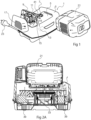
Fig 1 illustrates a charger and a battery pack to be charged. -
Figs 2A and2B show cross sections through the charger offig 1 with an inserted battery pack. - The present disclosure relates generally to a charger 1 in a battery-operated system, which charger is configured to charge a
battery pack 21, as illustrated with an example infig 1 . - Such a system may typically employ two or more
such battery packs 21 although this is not necessary. Usually, one battery pack is used in a tool (not shown), while the other is being charged. The present disclosure provides a charger 1 with improved reliability and safety. - The charger 1, as shown in
fig 1 , comprises a housing 3 and acharging socket 5 in the housing for receiving abattery pack 21. Typically, the charger comprises apower plug 23 adapted to be connected to an AC mains socket (not shown) and internal charging electronics, in anelectronics compartment 13, typically a rectifier and various control- and communications circuitry, adapted to convert received AC power and provide a DC charging current toelectric connectors 7 in thecharging socket 5 for charging thebattery pack 21. - Charging a
battery pack 21 in this way makes the cells in the battery pack develop heat, and the temperature of thebattery pack 21 should be kept down in order to provide efficient, fast charging, and to avoid damaging the cells in thebattery pack 21, for instance. To this end, a fan arrangement 9 is provided for force cooling thebattery pack 21 during charging. The fan arrangement 9 includes a motor and a fan driven by the motor. Thebattery pack 21 may comprise an air inlet and an air outlet as well as a channel extending therebetween in order to provide efficient cooling of cells therein, but it would also be conceivable to provide cooling by means of external cooling flange, with the cooling effect augmented by forced cooling, for instance. - The present disclosure provides improved safety and reliability of such a charger. The charger 1 is normally but not exclusively intended to be used indoors in dry conditions, but this does not always mean that the charger can be kept dry. For instance, if a
battery pack 21 has been used outdoors in cold or even freezing conditions, it may be very cold. Using the battery also means that it develops some heat and can be kept warm to some extent. However, a considerable time may have passed since the last use, and thebattery pack 21 may be at a temperature even below 0°C when brought indoors for charging. This means that condensation may be formed on the battery before heating up from charging and that condensation may drip into thecharging socket 5 of the charger 1. This implies a risk for malfunction of the charging electronics if water would enter in thecharging electronics compartment 13. - In the present disclosure, this problem is eliminated or reduced by providing the housing 3 with a
fan compartment 11. Thisfan compartment 11, which encloses the fan 9, is to some extent separate from anelectronics compartment 13 enclosing the charging electronics. Thefan compartment 11 and theelectronics compartment 13 are typically separated at least by awall 15. Thereby, the charging electronics can be protected from any moisture coming in contact with the fan arrangement 9. The fan arrangement 9 typically needs to be in contact with thecharging socket 5 to be able to cool thebattery pack 21 during charging. This is not the case for the charging electronics, however. Thus, by separating thefan compartment 11 from theelectronics compartment 13, the insulation of the latter and hence the safety and reliability of the charger can be improved in a cost-efficient manner. The fan arrangement 9 itself can have a higher rating with regard to moisture resistance and lead-throughs for driving the fan and connecting to theDC connectors 7 for the battery pack can be arranged in a watertight manner. - Typically, the fan compartment comprises an
air inlet 17 and anair outlet 19 to be able to create a flow through the fan compartment, but the fan compartment could also be open in different ways. Preferably however, the fan compartment has anair outlet 19 is connected to thecharging socket 5, such that efficient feeding of air towards the battery pack is achieved. Theair inlet 17 receives ambient air. - The
inlet 17 andoutlet 19 may be vertically oriented, at least extending in planes deviating less than 10 degrees from vertical when the charger is placed on a horizontal surface such that a too large area is not presented to matter, such as rain or dust, coming from above. This protects the inlet and outlet to some extent from rain coming from above if located outdoors. They could also face slightly downwards. - A
drain 41 is provided in thecharging socket 5 to lead away any water therefrom. Thisdrain 41 is located lower than the fancompartment air outlet 19, when the charger is placed on a horizontal surface, to prevent any moisture collected in the charging socket from entering thefan compartment 11. It may be preferred to locate thisdrain 41 in the vicinity of, or even more preferred in between,electric connectors 7 of the charger. This also keeps the electric connectors drier. - As the fan arrangement used to cool the battery pack is separated from the charging electronics, it may be preferred to arrange a separate cooling arrangement for the charging electronics which is not in direct contact with the charging
socket 5. One example of such a cooling arrangement is shown inFig 2A and2B illustrating cross sections through the charger offig 1 . This cooling arrangement comprises afan 31 that feeds ambient air from aninlet 35 in the bottom side of the charger housing 3, via a coolingflange 33, and to anoutlet 37 also in the bottom side thereof. The charger may rest onfeet 39 that project from the bottom side of the housing to provide an open space under the charger housing 3 by elevating the latter to some extent when resting for instance on a tabletop or the like. It is advantageous to locate theinlet 35 and theoutlet 37 in the bottom side of the housing where they are protected, although this is not necessary. One or both may also be located e.g. in the side walls of the housing, for instance. - As mentioned, there is provided a
cooling flange 33 in the air flow path, which may be closely connected with the charger electronics. The present disclosure considers providing theelectronics compartment 13 as a space defined by a set ofwalls flange 33. The coolingflange 33 is typically made from extruded aluminum while the remainder of the electronics compartment walls may be provided in one or more pieces by injection moulding plastics, for instance. A sealing device for instance comprising asilicone rubber gasket 43 may optionally be provided in between the cooling flange and the remainder of the electronics compartment walls, in order to provide a more watertight space. - With this configuration, the cooling
flange 33 is capable of serving the dual purposes of leading out generated heat from theelectronics compartment 13 and to seal off theelectronics compartment 13. This arrangement functions very well in combination with the separate fan compartment as described above, but the cooling flange serving this dual purpose could also be used in a charger where the battery pack is passively cooled or has its own internal cooling fan, for instance. - The present disclosure is not restricted to the above-described examples and may be varied and altered in different ways within the scope of the appended claims.
Claims (9)
- A charger (1) for a battery-operated system, configured to charge a battery pack, the charger comprising a housing (3) and a charging socket (5) in the housing for receiving a battery pack (21), charging electronics configured to provide a direct current to electric connectors (7) associated with the charging socket for charging the battery pack, and a fan arrangement (9) for force cooling the battery pack during charging, wherein the housing (3) comprises a fan compartment (11), enclosing the fan (9), and an electronics compartment (13), enclosing the charging electronics, wherein the fan compartment (11) and the electronics compartment (13) are separated at least by a wall (15), wherein the fan compartment (11) comprises an air inlet (17) and an air outlet (19), wherein the fan compartment air outlet (19) is connected to the charging socket (5), the charge being characterized in that it comprises a drain (41) in the charging socket (5), which is located lower than the fan compartment air outlet (19) when the charger is placed on a horizontal surface.
- Charger according to claim 1, wherein the air inlet (17) is connected to ambient air.
- Charger according to any of claims 1-2, wherein the air inlet (17) and air outlet (19) are substantially vertically oriented when the charger is placed on a horizontal surface.
- Charger according to any of the previous claims, wherein the drain is located in the vicinity of the electric connectors (7).
- Charger according to any of the previous claims, wherein the electronics compartment is enclosed by a set of walls, (41, 33), and wherein at least one such wall is made up from a cooling flange (33).
- Charger according to claim 5, wherein the cooling flange (33) is made of aluminum and the other walls (41) are made at least partly of plastic.
- Charger according to claim 5 or 6, wherein a gasket is provided in between the cooling flange (33) and the other walls (41).
- Charger according to any of claims 5-7, wherein the cooling flange (33) is located in a cooling channel which has its inlet (35) and outlet (37) located on the bottom side of the charger.
- Charger according to any of claims 5-8, wherein the housing (3) comprises a fan compartment (11), enclosing a fan (9) for cooling the battery pack, and wherein the fan compartment (11) and the electronics compartment (13) are separated at least by a wall (15).
Applications Claiming Priority (2)
| Application Number | Priority Date | Filing Date | Title |
|---|---|---|---|
| SE2150139 | 2021-02-09 | ||
| PCT/SE2022/050108 WO2022173344A1 (en) | 2021-02-09 | 2022-02-02 | Charger |
Publications (2)
| Publication Number | Publication Date |
|---|---|
| EP4292191A1 EP4292191A1 (en) | 2023-12-20 |
| EP4292191B1 true EP4292191B1 (en) | 2024-10-30 |
Family
ID=80787413
Family Applications (1)
| Application Number | Title | Priority Date | Filing Date |
|---|---|---|---|
| EP22704605.9A Active EP4292191B1 (en) | 2021-02-09 | 2022-02-02 | Charger |
Country Status (6)
| Country | Link |
|---|---|
| US (1) | US20240113539A1 (en) |
| EP (1) | EP4292191B1 (en) |
| JP (1) | JP7644249B2 (en) |
| CN (1) | CN116724474A (en) |
| AU (1) | AU2022219868A1 (en) |
| WO (1) | WO2022173344A1 (en) |
Family Cites Families (5)
| Publication number | Priority date | Publication date | Assignee | Title |
|---|---|---|---|---|
| JP3791214B2 (en) * | 1998-11-20 | 2006-06-28 | 日立工機株式会社 | Charger |
| JP2007265800A (en) * | 2006-03-28 | 2007-10-11 | Sanyo Electric Co Ltd | Charging cradle |
| TW200830662A (en) * | 2007-01-10 | 2008-07-16 | Mobiletron Electronics Co Ltd | Battery charger for power tool |
| JP6177709B2 (en) * | 2014-02-26 | 2017-08-09 | 株式会社マキタ | Charger |
| KR102813064B1 (en) * | 2019-12-03 | 2025-05-26 | 밀워키 일렉트릭 툴 코포레이션 | Battery pack and charger system |
-
2022
- 2022-02-02 EP EP22704605.9A patent/EP4292191B1/en active Active
- 2022-02-02 AU AU2022219868A patent/AU2022219868A1/en active Pending
- 2022-02-02 WO PCT/SE2022/050108 patent/WO2022173344A1/en not_active Ceased
- 2022-02-02 CN CN202280010840.9A patent/CN116724474A/en active Pending
- 2022-02-02 US US18/276,338 patent/US20240113539A1/en active Pending
- 2022-02-02 JP JP2023547843A patent/JP7644249B2/en active Active
Also Published As
| Publication number | Publication date |
|---|---|
| US20240113539A1 (en) | 2024-04-04 |
| JP7644249B2 (en) | 2025-03-11 |
| AU2022219868A1 (en) | 2023-07-06 |
| WO2022173344A1 (en) | 2022-08-18 |
| AU2022219868A9 (en) | 2024-02-08 |
| JP2024506620A (en) | 2024-02-14 |
| CN116724474A (en) | 2023-09-08 |
| EP4292191A1 (en) | 2023-12-20 |
Similar Documents
| Publication | Publication Date | Title |
|---|---|---|
| US11495908B2 (en) | Electrical connector assembly with liquid cooling features | |
| EP3793038B1 (en) | Electrical connector assembly | |
| US10630088B2 (en) | Battery charging device | |
| US7161803B1 (en) | Cooling system for an electronic display | |
| US7056616B2 (en) | Battery cooling system | |
| EP2824795B1 (en) | Battery charger capable of efficiently cooling secondary battery in battery pack and charging circuit unit in battery charger | |
| US10103558B2 (en) | Charger, charging system and power tool with battery pack | |
| US20150340746A1 (en) | Battery module provided with a peltier cell | |
| US10601236B2 (en) | Battery charging device | |
| CN113764774B (en) | Radiator box, battery pack system and electrical equipment | |
| WO2020170442A1 (en) | Charging/discharging device | |
| CN111029502A (en) | A battery box for railway tractor | |
| CN211575304U (en) | window air conditioner | |
| EP4292191B1 (en) | Charger | |
| CN219419272U (en) | Battery protection device of electric automobile | |
| CN220062200U (en) | Heating and ventilation equipment | |
| CN211575306U (en) | Electric Control Box and Window Air Conditioner | |
| CN211575303U (en) | Electric Control Box and Window Air Conditioner | |
| CN206195418U (en) | Charger | |
| JP4250785B2 (en) | Charger | |
| CN211575305U (en) | Electric Control Box and Window Air Conditioner | |
| CN218386903U (en) | Heat dissipation shell and charger of charger | |
| CN215578214U (en) | Explosion-proof capacitor | |
| CN206432856U (en) | A kind of permanent magnetic synchronous motor structure | |
| CN115696822A (en) | Vehicle-mounted power inverter with waterproof function |
Legal Events
| Date | Code | Title | Description |
|---|---|---|---|
| STAA | Information on the status of an ep patent application or granted ep patent |
Free format text: STATUS: UNKNOWN |
|
| STAA | Information on the status of an ep patent application or granted ep patent |
Free format text: STATUS: THE INTERNATIONAL PUBLICATION HAS BEEN MADE |
|
| PUAI | Public reference made under article 153(3) epc to a published international application that has entered the european phase |
Free format text: ORIGINAL CODE: 0009012 |
|
| STAA | Information on the status of an ep patent application or granted ep patent |
Free format text: STATUS: REQUEST FOR EXAMINATION WAS MADE |
|
| 17P | Request for examination filed |
Effective date: 20230626 |
|
| AK | Designated contracting states |
Kind code of ref document: A1 Designated state(s): AL AT BE BG CH CY CZ DE DK EE ES FI FR GB GR HR HU IE IS IT LI LT LU LV MC MK MT NL NO PL PT RO RS SE SI SK SM TR |
|
| DAV | Request for validation of the european patent (deleted) | ||
| DAX | Request for extension of the european patent (deleted) | ||
| GRAP | Despatch of communication of intention to grant a patent |
Free format text: ORIGINAL CODE: EPIDOSNIGR1 |
|
| STAA | Information on the status of an ep patent application or granted ep patent |
Free format text: STATUS: GRANT OF PATENT IS INTENDED |
|
| INTG | Intention to grant announced |
Effective date: 20240702 |
|
| GRAS | Grant fee paid |
Free format text: ORIGINAL CODE: EPIDOSNIGR3 |
|
| GRAA | (expected) grant |
Free format text: ORIGINAL CODE: 0009210 |
|
| STAA | Information on the status of an ep patent application or granted ep patent |
Free format text: STATUS: THE PATENT HAS BEEN GRANTED |
|
| P01 | Opt-out of the competence of the unified patent court (upc) registered |
Free format text: CASE NUMBER: APP_50535/2024 Effective date: 20240905 |
|
| AK | Designated contracting states |
Kind code of ref document: B1 Designated state(s): AL AT BE BG CH CY CZ DE DK EE ES FI FR GB GR HR HU IE IS IT LI LT LU LV MC MK MT NL NO PL PT RO RS SE SI SK SM TR |
|
| REG | Reference to a national code |
Ref country code: GB Ref legal event code: FG4D |
|
| REG | Reference to a national code |
Ref country code: CH Ref legal event code: EP |
|
| REG | Reference to a national code |
Ref country code: IE Ref legal event code: FG4D |
|
| REG | Reference to a national code |
Ref country code: DE Ref legal event code: R096 Ref document number: 602022007268 Country of ref document: DE |
|
| REG | Reference to a national code |
Ref country code: NL Ref legal event code: FP |
|
| REG | Reference to a national code |
Ref country code: LT Ref legal event code: MG9D |
|
| PG25 | Lapsed in a contracting state [announced via postgrant information from national office to epo] |
Ref country code: IS Free format text: LAPSE BECAUSE OF FAILURE TO SUBMIT A TRANSLATION OF THE DESCRIPTION OR TO PAY THE FEE WITHIN THE PRESCRIBED TIME-LIMIT Effective date: 20250228 Ref country code: PT Free format text: LAPSE BECAUSE OF FAILURE TO SUBMIT A TRANSLATION OF THE DESCRIPTION OR TO PAY THE FEE WITHIN THE PRESCRIBED TIME-LIMIT Effective date: 20250228 Ref country code: HR Free format text: LAPSE BECAUSE OF FAILURE TO SUBMIT A TRANSLATION OF THE DESCRIPTION OR TO PAY THE FEE WITHIN THE PRESCRIBED TIME-LIMIT Effective date: 20241030 |
|
| PG25 | Lapsed in a contracting state [announced via postgrant information from national office to epo] |
Ref country code: FI Free format text: LAPSE BECAUSE OF FAILURE TO SUBMIT A TRANSLATION OF THE DESCRIPTION OR TO PAY THE FEE WITHIN THE PRESCRIBED TIME-LIMIT Effective date: 20241030 |
|
| REG | Reference to a national code |
Ref country code: AT Ref legal event code: MK05 Ref document number: 1737887 Country of ref document: AT Kind code of ref document: T Effective date: 20241030 |
|
| PG25 | Lapsed in a contracting state [announced via postgrant information from national office to epo] |
Ref country code: BG Free format text: LAPSE BECAUSE OF FAILURE TO SUBMIT A TRANSLATION OF THE DESCRIPTION OR TO PAY THE FEE WITHIN THE PRESCRIBED TIME-LIMIT Effective date: 20241030 |
|
| PG25 | Lapsed in a contracting state [announced via postgrant information from national office to epo] |
Ref country code: ES Free format text: LAPSE BECAUSE OF FAILURE TO SUBMIT A TRANSLATION OF THE DESCRIPTION OR TO PAY THE FEE WITHIN THE PRESCRIBED TIME-LIMIT Effective date: 20241030 |
|
| PG25 | Lapsed in a contracting state [announced via postgrant information from national office to epo] |
Ref country code: NO Free format text: LAPSE BECAUSE OF FAILURE TO SUBMIT A TRANSLATION OF THE DESCRIPTION OR TO PAY THE FEE WITHIN THE PRESCRIBED TIME-LIMIT Effective date: 20250130 |
|
| PG25 | Lapsed in a contracting state [announced via postgrant information from national office to epo] |
Ref country code: AT Free format text: LAPSE BECAUSE OF FAILURE TO SUBMIT A TRANSLATION OF THE DESCRIPTION OR TO PAY THE FEE WITHIN THE PRESCRIBED TIME-LIMIT Effective date: 20241030 Ref country code: GR Free format text: LAPSE BECAUSE OF FAILURE TO SUBMIT A TRANSLATION OF THE DESCRIPTION OR TO PAY THE FEE WITHIN THE PRESCRIBED TIME-LIMIT Effective date: 20250131 Ref country code: LV Free format text: LAPSE BECAUSE OF FAILURE TO SUBMIT A TRANSLATION OF THE DESCRIPTION OR TO PAY THE FEE WITHIN THE PRESCRIBED TIME-LIMIT Effective date: 20241030 |
|
| PG25 | Lapsed in a contracting state [announced via postgrant information from national office to epo] |
Ref country code: PL Free format text: LAPSE BECAUSE OF FAILURE TO SUBMIT A TRANSLATION OF THE DESCRIPTION OR TO PAY THE FEE WITHIN THE PRESCRIBED TIME-LIMIT Effective date: 20241030 |
|
| PG25 | Lapsed in a contracting state [announced via postgrant information from national office to epo] |
Ref country code: RS Free format text: LAPSE BECAUSE OF FAILURE TO SUBMIT A TRANSLATION OF THE DESCRIPTION OR TO PAY THE FEE WITHIN THE PRESCRIBED TIME-LIMIT Effective date: 20250130 |
|
| PG25 | Lapsed in a contracting state [announced via postgrant information from national office to epo] |
Ref country code: SM Free format text: LAPSE BECAUSE OF FAILURE TO SUBMIT A TRANSLATION OF THE DESCRIPTION OR TO PAY THE FEE WITHIN THE PRESCRIBED TIME-LIMIT Effective date: 20241030 |
|
| PG25 | Lapsed in a contracting state [announced via postgrant information from national office to epo] |
Ref country code: DK Free format text: LAPSE BECAUSE OF FAILURE TO SUBMIT A TRANSLATION OF THE DESCRIPTION OR TO PAY THE FEE WITHIN THE PRESCRIBED TIME-LIMIT Effective date: 20241030 |
|
| PG25 | Lapsed in a contracting state [announced via postgrant information from national office to epo] |
Ref country code: EE Free format text: LAPSE BECAUSE OF FAILURE TO SUBMIT A TRANSLATION OF THE DESCRIPTION OR TO PAY THE FEE WITHIN THE PRESCRIBED TIME-LIMIT Effective date: 20241030 |
|
| PG25 | Lapsed in a contracting state [announced via postgrant information from national office to epo] |
Ref country code: RO Free format text: LAPSE BECAUSE OF FAILURE TO SUBMIT A TRANSLATION OF THE DESCRIPTION OR TO PAY THE FEE WITHIN THE PRESCRIBED TIME-LIMIT Effective date: 20241030 |
|
| PG25 | Lapsed in a contracting state [announced via postgrant information from national office to epo] |
Ref country code: SK Free format text: LAPSE BECAUSE OF FAILURE TO SUBMIT A TRANSLATION OF THE DESCRIPTION OR TO PAY THE FEE WITHIN THE PRESCRIBED TIME-LIMIT Effective date: 20241030 |
|
| PG25 | Lapsed in a contracting state [announced via postgrant information from national office to epo] |
Ref country code: CZ Free format text: LAPSE BECAUSE OF FAILURE TO SUBMIT A TRANSLATION OF THE DESCRIPTION OR TO PAY THE FEE WITHIN THE PRESCRIBED TIME-LIMIT Effective date: 20241030 |
|
| PG25 | Lapsed in a contracting state [announced via postgrant information from national office to epo] |
Ref country code: IT Free format text: LAPSE BECAUSE OF FAILURE TO SUBMIT A TRANSLATION OF THE DESCRIPTION OR TO PAY THE FEE WITHIN THE PRESCRIBED TIME-LIMIT Effective date: 20241030 |
|
| REG | Reference to a national code |
Ref country code: DE Ref legal event code: R097 Ref document number: 602022007268 Country of ref document: DE |
|
| PLBE | No opposition filed within time limit |
Free format text: ORIGINAL CODE: 0009261 |
|
| STAA | Information on the status of an ep patent application or granted ep patent |
Free format text: STATUS: NO OPPOSITION FILED WITHIN TIME LIMIT |
|
| PG25 | Lapsed in a contracting state [announced via postgrant information from national office to epo] |
Ref country code: SE Free format text: LAPSE BECAUSE OF FAILURE TO SUBMIT A TRANSLATION OF THE DESCRIPTION OR TO PAY THE FEE WITHIN THE PRESCRIBED TIME-LIMIT Effective date: 20241030 |
|
| PG25 | Lapsed in a contracting state [announced via postgrant information from national office to epo] |
Ref country code: MC Free format text: LAPSE BECAUSE OF FAILURE TO SUBMIT A TRANSLATION OF THE DESCRIPTION OR TO PAY THE FEE WITHIN THE PRESCRIBED TIME-LIMIT Effective date: 20241030 |
|
| REG | Reference to a national code |
Ref country code: CH Ref legal event code: PL |
|
| 26N | No opposition filed |
Effective date: 20250731 |
|
| PG25 | Lapsed in a contracting state [announced via postgrant information from national office to epo] |
Ref country code: LU Free format text: LAPSE BECAUSE OF NON-PAYMENT OF DUE FEES Effective date: 20250202 |
|
| PG25 | Lapsed in a contracting state [announced via postgrant information from national office to epo] |
Ref country code: CH Free format text: LAPSE BECAUSE OF NON-PAYMENT OF DUE FEES Effective date: 20250228 |
|
| REG | Reference to a national code |
Ref country code: BE Ref legal event code: MM Effective date: 20250228 |
|
| PG25 | Lapsed in a contracting state [announced via postgrant information from national office to epo] |
Ref country code: BE Free format text: LAPSE BECAUSE OF NON-PAYMENT OF DUE FEES Effective date: 20250228 |
|
| PG25 | Lapsed in a contracting state [announced via postgrant information from national office to epo] |
Ref country code: IE Free format text: LAPSE BECAUSE OF NON-PAYMENT OF DUE FEES Effective date: 20250202 |
|
| PGFP | Annual fee paid to national office [announced via postgrant information from national office to epo] |
Ref country code: NL Payment date: 20260113 Year of fee payment: 5 |
|
| PGFP | Annual fee paid to national office [announced via postgrant information from national office to epo] |
Ref country code: DE Payment date: 20260109 Year of fee payment: 5 |
|
| PGFP | Annual fee paid to national office [announced via postgrant information from national office to epo] |
Ref country code: FR Payment date: 20260113 Year of fee payment: 5 |