EP4291293B1 - Systeme zur programmierung von neuromodulationssequenzen - Google Patents
Systeme zur programmierung von neuromodulationssequenzen Download PDFInfo
- Publication number
- EP4291293B1 EP4291293B1 EP22707567.8A EP22707567A EP4291293B1 EP 4291293 B1 EP4291293 B1 EP 4291293B1 EP 22707567 A EP22707567 A EP 22707567A EP 4291293 B1 EP4291293 B1 EP 4291293B1
- Authority
- EP
- European Patent Office
- Prior art keywords
- blocks
- neuromodulation
- electrodes
- sequence
- block
- Prior art date
- Legal status (The legal status is an assumption and is not a legal conclusion. Google has not performed a legal analysis and makes no representation as to the accuracy of the status listed.)
- Active
Links
Images


Classifications
-
- A—HUMAN NECESSITIES
- A61—MEDICAL OR VETERINARY SCIENCE; HYGIENE
- A61N—ELECTROTHERAPY; MAGNETOTHERAPY; RADIATION THERAPY; ULTRASOUND THERAPY
- A61N1/00—Electrotherapy; Circuits therefor
- A61N1/18—Applying electric currents by contact electrodes
- A61N1/32—Applying electric currents by contact electrodes alternating or intermittent currents
- A61N1/36—Applying electric currents by contact electrodes alternating or intermittent currents for stimulation
- A61N1/3605—Implantable neurostimulators for stimulating central or peripheral nerve system
- A61N1/36125—Details of circuitry or electric components
-
- A—HUMAN NECESSITIES
- A61—MEDICAL OR VETERINARY SCIENCE; HYGIENE
- A61N—ELECTROTHERAPY; MAGNETOTHERAPY; RADIATION THERAPY; ULTRASOUND THERAPY
- A61N1/00—Electrotherapy; Circuits therefor
- A61N1/18—Applying electric currents by contact electrodes
- A61N1/32—Applying electric currents by contact electrodes alternating or intermittent currents
- A61N1/36—Applying electric currents by contact electrodes alternating or intermittent currents for stimulation
- A61N1/3605—Implantable neurostimulators for stimulating central or peripheral nerve system
- A61N1/36128—Control systems
- A61N1/36132—Control systems using patient feedback
-
- A—HUMAN NECESSITIES
- A61—MEDICAL OR VETERINARY SCIENCE; HYGIENE
- A61N—ELECTROTHERAPY; MAGNETOTHERAPY; RADIATION THERAPY; ULTRASOUND THERAPY
- A61N1/00—Electrotherapy; Circuits therefor
- A61N1/18—Applying electric currents by contact electrodes
- A61N1/32—Applying electric currents by contact electrodes alternating or intermittent currents
- A61N1/36—Applying electric currents by contact electrodes alternating or intermittent currents for stimulation
- A61N1/3605—Implantable neurostimulators for stimulating central or peripheral nerve system
- A61N1/36128—Control systems
- A61N1/36146—Control systems specified by the stimulation parameters
- A61N1/36182—Direction of the electrical field, e.g. with sleeve around stimulating electrode
- A61N1/36185—Selection of the electrode configuration
-
- A—HUMAN NECESSITIES
- A61—MEDICAL OR VETERINARY SCIENCE; HYGIENE
- A61N—ELECTROTHERAPY; MAGNETOTHERAPY; RADIATION THERAPY; ULTRASOUND THERAPY
- A61N1/00—Electrotherapy; Circuits therefor
- A61N1/18—Applying electric currents by contact electrodes
- A61N1/32—Applying electric currents by contact electrodes alternating or intermittent currents
- A61N1/36—Applying electric currents by contact electrodes alternating or intermittent currents for stimulation
- A61N1/372—Arrangements in connection with the implantation of stimulators
- A61N1/37211—Means for communicating with stimulators
- A61N1/37217—Means for communicating with stimulators characterised by the communication link, e.g. acoustic or tactile
-
- A—HUMAN NECESSITIES
- A61—MEDICAL OR VETERINARY SCIENCE; HYGIENE
- A61N—ELECTROTHERAPY; MAGNETOTHERAPY; RADIATION THERAPY; ULTRASOUND THERAPY
- A61N1/00—Electrotherapy; Circuits therefor
- A61N1/18—Applying electric currents by contact electrodes
- A61N1/32—Applying electric currents by contact electrodes alternating or intermittent currents
- A61N1/36—Applying electric currents by contact electrodes alternating or intermittent currents for stimulation
- A61N1/372—Arrangements in connection with the implantation of stimulators
- A61N1/37211—Means for communicating with stimulators
- A61N1/37235—Aspects of the external programmer
- A61N1/37247—User interfaces, e.g. input or presentation means
-
- A—HUMAN NECESSITIES
- A61—MEDICAL OR VETERINARY SCIENCE; HYGIENE
- A61N—ELECTROTHERAPY; MAGNETOTHERAPY; RADIATION THERAPY; ULTRASOUND THERAPY
- A61N1/00—Electrotherapy; Circuits therefor
- A61N1/18—Applying electric currents by contact electrodes
- A61N1/32—Applying electric currents by contact electrodes alternating or intermittent currents
- A61N1/36—Applying electric currents by contact electrodes alternating or intermittent currents for stimulation
- A61N1/372—Arrangements in connection with the implantation of stimulators
- A61N1/37211—Means for communicating with stimulators
- A61N1/37252—Details of algorithms or data aspects of communication system, e.g. handshaking, transmitting specific data or segmenting data
-
- G—PHYSICS
- G16—INFORMATION AND COMMUNICATION TECHNOLOGY [ICT] SPECIALLY ADAPTED FOR SPECIFIC APPLICATION FIELDS
- G16H—HEALTHCARE INFORMATICS, i.e. INFORMATION AND COMMUNICATION TECHNOLOGY [ICT] SPECIALLY ADAPTED FOR THE HANDLING OR PROCESSING OF MEDICAL OR HEALTHCARE DATA
- G16H40/00—ICT specially adapted for the management or administration of healthcare resources or facilities; ICT specially adapted for the management or operation of medical equipment or devices
- G16H40/60—ICT specially adapted for the management or administration of healthcare resources or facilities; ICT specially adapted for the management or operation of medical equipment or devices for the operation of medical equipment or devices
- G16H40/63—ICT specially adapted for the management or administration of healthcare resources or facilities; ICT specially adapted for the management or operation of medical equipment or devices for the operation of medical equipment or devices for local operation
-
- H—ELECTRICITY
- H04—ELECTRIC COMMUNICATION TECHNIQUE
- H04W—WIRELESS COMMUNICATION NETWORKS
- H04W4/00—Services specially adapted for wireless communication networks; Facilities therefor
- H04W4/20—Services signaling; Auxiliary data signalling, i.e. transmitting data via a non-traffic channel
Definitions
- This document relates generally to medical systems, and more particularly, but not by way of limitation, to systems, devices, and methods for programming neuromodulation therapy.
- Neuromodulation also referred to as neurostimulation
- neurostimulation has been proposed as a therapy for a number of conditions.
- Examples of neuromodulation include Spinal Cord Stimulation (SCS), Deep Brain Stimulation (DBS), Peripheral Nerve Stimulation (PNS), and Functional Electrical Stimulation (FES).
- SCS Spinal Cord Stimulation
- DBS Deep Brain Stimulation
- PNS Peripheral Nerve Stimulation
- FES Functional Electrical Stimulation
- Implantable neuromodulation systems have been applied to deliver a neuromodulation therapy.
- An implantable neuromodulation system may include an implantable neuromodulator, also referred to as an implantable wave generator or an implantable pulse generator (IPG), and one or more implantable leads each including one or more electrodes.
- IPG implantable pulse generator
- the implantable neuromodulator delivers neuromodulation energy through one or more electrodes placed on or near a target site in the nervous system.
- An external programming device may be used to program the implantable neuromodulator with modulation parameters controlling the delivery of the neuromodulation energy.
- the neuromodulation energy may be delivered using an electrical modulation waveform, which may be defined by a plurality of modulation parameters.
- electrical modulation waveform may be an electrical pulsed waveform.
- Other parameters that may be controlled or varied include the electrodes within the electrode array that are activated, the amplitude, pulse width, and rate (or frequency) of the electrical pulses provided to individual ones of the activated electrodes.
- US 2018/214699 A1 discloses a system for receiving a target neuromodulation field location within a patient for a neuromodulation field.
- US 10 456 583 B2 discloses a neuromodulation device configured with a set of testing program configuration instructions including therapeutic neuromodulation field-setting parameters. The device determines a custom priming program in response to the testing program configuration instructions.
- US 10 617 872 B2 discloses a system for programming a neuromodulation therapy to treat neurological or cardiovascular diseases.
- US 2009/326608 A1 discloses a method for assisting programming a pulse generator which comprises defining a set of unique electrode combinations in the controller device.
- the modulation waveform may comprise multiple pulses with distinct shapes or morphology, as characterized by distinct pulse amplitudes, pulse widths, pulse rates, or other pulse morphological parameters.
- the multitude of modulation parameters may also include an electrode configuration used to deliver electrical pulses to the targeted tissue.
- the electrodes may be capable of being selectively programmed to act as anodes (positive), cathodes (negative), or left off (zero).
- Other parameters that may be controlled or varied include the amplitude, pulse width, and rate (or frequency) of the electrical pulses provided to individual electrodes or groups of two or more electrodes within the electrode array.
- Each electrode configuration, along with the electrical pulse parameters, constitutes a modulation parameter set for use in an electrostimulation therapy.
- the present subject matter relates to constructs and optimizations that enable efficient storage and delivery of neuromodulation patterns within the neuromodulator hardware.
- These patterns may include a sequence of spatially-different neuromodulation fields. That is, one neuromodulation field and a subsequent neuromodulation field in the sequence may cover different tissue volumes using different neuromodulation field shapes and/or locations of the neuromodulation fields.
- these patterns may include two or more sequences of spatially-different neuromodulation fields, where the two or more sequences are generated using two or more neuromodulation channels and are delivered to two or more neural targets, respectively.
- such neuromodulation patterns may include but are not limited to patterns such as may be used in a coordinated reset (CR) therapy.
- CR coordinated reset
- CR therapy refers to a therapy that attempts to disrupt abnormal neuronal synchronization using patterns that include both spatial and temporal patterns to desynchronize the abnormal synchronous neuronal activity by delivering phase resetting stimuli at different times to different sub-populations involved with the abnormal neuronal synchronization.
- sequences are built of blocks with each block associated with a fixed field. Furthermore, the blocks have timing relationships with other block(s).
- each CR sequence may be associated with a list of fields; each CR sequence may be associated with a specified number of On and Off blocks; each CR sequence may be associated with a Duty Cycle; each CR field may be associated with a unique amplitude, pulse width and rate; and each block may be associated with a field order.
- a programmer system may take the sequence definition information as input and translate it to a series of neuromodulator instructions.
- the programmer system may optimize the instructions to update multiple Application Specific Integrated Circuit (ASIC) register settings at the same time and to minimize memory usage.
- ASIC Application Specific Integrated Circuit
- FIG. 1 illustrates, by way of example, an embodiment of a neuromodulation system.
- the illustrated neuromodulation system 100 includes electrodes 101, a modulation device 102, and a programming system such as a programming device 103.
- the programming system may include multiple devices.
- the electrodes 101 are configured to be placed on or near one or more neural targets in a patient.
- the modulation device 102 is configured to be electrically connected to electrodes 101 and deliver neuromodulation energy, such as in the form of electrical pulses, to the one or more neural targets though electrodes 101.
- the delivery of the neuromodulation is controlled using a plurality of modulation parameters that may specify the electrical waveform (e.g. pulses or pulse patterns or other waveform shapes) and a selection of electrodes through which the electrical waveform is delivered.
- the programming device 103 provides the user with accessibility to the user-programmable parameters.
- the programming device 103 is configured to be communicatively coupled to modulation device via a wired or wireless link.
- the programming device 103 includes a user interface 104 such as a graphical user interface (GUI) that allows the user to set and/or adjust values of the user-programmable modulation parameters.
- GUI graphical user interface
- FIG. 2 illustrates, by way of examples and not limitation, the neuromodulation system of FIG. 1 implemented in a spinal cord stimulation (SCS) system or a deep brain stimulation (DBS) system.
- the illustrated neuromodulation system 200 includes an external system 205 that may include at least one programming device, which is illustrated as an external time 205.
- the illustrated external system 205 may include a clinician programmer 206 configured for use by a clinician to communicate with and program the neuromodulator, and a remote control 207 configured for use by the patient to communicate with and program the neuromodulator.
- the remote control device may allow the patient to turn a therapy on and off and/or adjust certain patient-programmable parameters of the plurality of modulation parameters.
- FIG. 2 illustrates a modulation device as an ambulatory medical device 202. Examples of ambulatory devices include wearable or implantable neuromodulators.
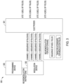
- FIG. 3 illustrates, by way of example and not limitation, an embodiment of the neuromodulation system of FIGS. 1-2 configured to program more than one channel of neuromodulation with block sequences for generating a sequence of spatially-different neuromodulation fields at more than one neuromodulation site.
- the illustrated system 300 includes electrodes 301, a modulation device 302, and a programming system such as a programming device 303.
- the illustrated modulation device 302 is configured to generate neuromodulation over more than one timing channel.
- the modulation device 302 may be configured with a capability to use four timing channels to generate the neuromodulation.
- a timing channel identifies which electrodes are selected to synchronously source or sink current to create an electric field in the tissue to be stimulated.
- Amplitudes and polarities of electrodes on a channel may vary.
- the electrodes can be selected to be positive (anode, sourcing current), negative (cathode, sinking current), or off (no current) polarity in any of the k timing channels.
- each timing channel may be assigned a modulation parameter set, which may include both an electrode configuration (e.g. electrodes selectively programmed to act as anodes (positive), cathodes (negative), or left off (zero)) and waveform parameters (e.g. pulse parameters such as pulse amplitude, pulse width, pulse frequency or variable pulse-to-pulse timing).
- each channel may correspond to its own neurostimulation site (e.g. a volume of tissue in which one or more neuromodulation fields are delivered). Subsequent blocks of time on the timing channel may have different parameter sets.
- a single timing channel may use a sequence of these parameter sets, also referred to herein as a sequence of blocks, to generate a sequence of modulation fields.
- each timing channel may be used to generate its own sequence of modulation fields as well as to control timing relationships between the fields.
- One or more of these channels may be used to deliver CR therapy to deliver spatial and temporal patterns to different neuronal sub-populations for desynchronizing abnormal synchronous neuronal activity.
- the programming device 303 is configured to receive user input related to the sequence of modulation fields and/or the timing relationship for the modulation field, and translate the user input into neuromodulation instructions to be communicated to the modulation device 302.
- the communicated neuromodulation instructions may be firmware instructions used by firmware within the modulation device to generate the programmed sequences and timing in each of the channels.
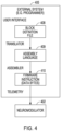
- FIG. 4 illustrates, by way of example and not limitation, a process for translating user-inputted block definition files into firmware instructions for wireless communication (e.g. telemetry) to program a modulation device.
- An external system (e.g. programmer) 405 may include a user interface configured for use to input sequence definition information and form a block definition file 408.
- the programmer may include a translator that is configured to translate the block definition file 408 into assembly language 409.
- the programmer may further include an assembler configured to assemble the assembly language 409 into firmware instructions (e.g. a series of neuromodulator instructions in data bytes for storage into registers of the neuromodulator) 410.
- the external system 405 may include telemetry to communicate the firmware instructions to the neuromodulator 402.
- sequences of spatially-different neuromodulation fields and the timing relationship(s) are transformed into instructions that the neuromodulator can understand in order to implement such sequences of neuromodulation patterns. These steps are efficiently performed for these complex patterns. Sequences are built of blocks with each block associated with a fixed field. Furthermore, the blocks have timing relationships with other block(s).
- the sequences may include CR sequences. Each CR sequence may be associated with a list of fields. Each CR sequence may be associated with a specified number of On and Off blocks. Each CR sequence may be associated with a Duty Cycle. Each CR field may be associated with a unique amplitude, pulse width and rate. Each block is associated with a field order. Unique features, such as these identified features for CR sequences, may be used to construct the neuromodulator instructions.
- the present subject matter is not limited to pulses, but may include other electrical waveforms (e.g. waveforms with different waveform shapes, and waveforms with various pulse patterns).
- the multi-channel neuromodulation output circuit 511 may include a plurality of independent sources 513 (e.g. independent voltage sources or independent current sources).
- the modulation control circuit 512 controls the delivery of the neuromodulation pulses using the plurality of modulation parameters.
- the modulation parameters include parameters for defining the sequence of blocks (e.g. modulation fields) 514 and parameters defining timing relationship(s) 515 for the blocks. These parameters provide firmware instructions for each timing channel of the neuromodulator, and may be stored in registers within the neuromodulator.
- circuitry that may be used to generate and deliver neuromodulation pulses are found in the following references, which are herein incorporated by reference in their entirety: U.S. Pat. No. 9,974,958 , entitled System and Method for Independently Operating Multiple Neurostimulation Channels; U.S. Pat. No. 9,446,231 , entitled Neurostimulation System and Method for Compounding Current to Minimize Current Sources; and U.S. Pat. No. 8,620,436 , entitled Current Generation Architecture for an Implantable Stimulator Device Having Course and Fine Current Control.
- the electrodes 501 may be on one or more leads that are configured to be electrically connected to modulation device 502.
- the electrodes 501 may include a plurality of electrodes 501-1 to 501-N distributed in an electrode arrangement.
- the neuromodulation pulses are each delivered from the modulation output circuit 502 through a set of electrodes selected from the N electrodes that are available for selection.
- the number of leads and the number of electrodes on each lead may depend on, for example, the distribution of target(s) of the neuromodulation and the need for controlling the distribution of electric field at each target.
- the lead system includes two leads where each lead has eight electrodes. Some embodiments may use a lead system that includes a paddle lead.
- Some embodiments may include a directional lead that includes at least some segmented electrodes circumferentially disposed about the directional lead. Two or more segmented electrodes may be distributed along a circumference of the lead. The type, number and shape of leads and electrodes may vary according to the intended application.
- the neuromodulation system may be configured to modulate brain tissue, configured to modulate spinal target tissue or configured to modulate other neural tissue.
- the configuration of electrodes used to deliver electrical pulses to the targeted tissue constitutes an electrode configuration, with the electrodes capable of being selectively programmed to act as anodes (positive), cathodes (negative), or left off (zero). In other words, an electrode configuration represents the polarity being positive, negative, or zero.
- An electrical waveform may be controlled or varied for delivery using electrode configuration(s).
- the electrical waveforms may be analog or digital signals.
- the electrical waveform includes pulses.
- the pulses may be delivered in a regular, repeating pattern, or may be delivered using complex patterns of pulses that appear to be irregular.
- Each electrode configuration, along with the electrical pulse parameters, can be referred to as a "modulation parameter set.”
- Each set of modulation parameters including fractionalized current distribution to the electrodes (as percentage cathodic current, percentage anodic current, or off), may be stored and combined into a modulation program that can then be used to modulate multiple regions within the patient.
- the number of electrodes available presents a huge selection of modulation parameter sets to the clinician or patient.
- the neuromodulation system to be programmed has sixteen electrodes, millions of modulation parameter sets may be available for programming into the neuromodulation system.
- some neuromodulation systems may have thirty-two electrodes which exponentially increases the number of modulation parameters sets available for programming.
- the programming device 503 in the illustrated system 500 may include a storage device 517, a programming control circuit 518, and a graphical user interface (GUI) 504.
- the programming control circuit 518 generates the plurality of modulation parameters that controls neuromodulation energy generated by the modulation device.
- the GUI 504 may include any type of presentation device, such as interactive or non-interactive screens, and any type of user input devices that allow the user to program the modulation parameters, such as touchscreen, keyboard, keypad, touchpad, trackball, joystick, and mouse.
- the storage device 517 may store, among other things, modulation parameters to be programmed into the modulation device. Telemetry may be used to communicate between the programming device 503 and the modulation device 502.
- the programming device 503 may transmit the plurality of modulation parameters to the modulation device 502. In some embodiments, the programming device 503 may transmit power to the modulation device 502.
- the programming control circuit 518 may generate the plurality of modulation parameters.
- a translator 519 may be used to translate the block definition file into assembly language, and an assembler 520 configured to assemble the assembly language into firmware instructions for transmission to the modulation device and storage in the registers 516.
- the programming control circuit 518 may check values of the plurality of modulation parameters against safety rules to limit these values within constraints of the safety rules.
- circuits of neuromodulation may be implemented using a combination of hardware, software and firmware.
- the circuit of GUI, modulation control circuit, and programming control circuit may be implemented using an application-specific circuit constructed to perform one or more particular functions or a general-purpose circuit programmed to perform such function(s).
- a general-purpose circuit includes, but is not limited to, a microprocessor or a portion thereof, a microcontroller or portions thereof, and a programmable logic circuit or a portion thereof.
- FIG. 6 illustrates, by way of example, some features of the neuromodulation leads 621 and a waveform generator 622.
- the waveform generator 622 may be an implantable device or may be an external device such as may be used to test the electrodes during an implantation procedure.
- one of the neuromodulation leads has eight electrodes (labeled E1-E8), and the other neuromodulation lead has eight electrodes (labeled E9-E16).
- the actual number and shape of leads and electrodes may vary for the intended application.
- An implantable waveform generator 622 may include an outer case for housing the electronic and other components.
- the outer case may be composed of an electrically conductive, biocompatible material, such as titanium, that forms a hermetically-sealed compartment wherein the internal electronics are protected from the body tissue and fluids.
- the outer case may serve as an electrode (e.g. case electrode).
- the waveform generator 622 may include electronic components, such as a controller/processor (e.g., a microcontroller), memory, a battery, telemetry circuitry, monitoring circuitry, modulation output circuitry, and other suitable components known to those skilled in the art.
- the microcontroller executes a suitable program stored in memory, for directing and controlling the neuromodulation performed by the waveform generator. Electrical modulation energy is provided to the electrodes in accordance with a set of modulation parameters programmed into the pulse generator.
- the electrical modulation energy may be in the form of a pulsed electrical waveform.
- modulation parameters may comprise electrode combinations, which define the electrodes that are activated as anodes (positive), cathodes (negative), and turned off (zero), percentage of modulation energy assigned to each electrode (which may also be referred to as allocated energy or fractionalized electrode configurations), and electrical pulse parameters, which define the pulse amplitude (measured in milliamps or volts depending on whether the pulse generator supplies constant current or constant voltage to the electrode array), pulse width (measured in microseconds), pulse rate (measured in pulses per second), and burst rate (measured as the modulation on duration X and modulation off duration Y). Electrodes that are selected to transmit or receive electrical energy are referred to herein as "activated,” while electrodes that are not selected to transmit or receive electrical energy are referred to herein as "non-activated.”
- Electrode modulation occurs between or among a plurality of activated electrodes, one of which may be the case of the waveform generator.
- the system may be capable of transmitting modulation energy to the tissue in a monopolar or multipolar (e.g., bipolar, tripolar, or more than three poles) fashion.
- Monopolar modulation occurs when a selected one of the lead electrodes is activated along with the case of the waveform generator, so that modulation energy is transmitted between the selected electrode and case.
- Any of the electrodes E1-E16 and the case electrode may be assigned to up to k possible groups or timing "channels.” In one embodiment, k may equal four.
- the timing channel identifies which electrodes are selected to synchronously source or sink current to create an electric field in the tissue to be stimulated.
- Amplitudes and polarities of electrodes on a channel may vary.
- the electrodes can be selected to be positive (anode, sourcing current), negative (cathode, sinking current), or off (no current) polarity in any of the k timing channels.
- the waveform generator 622 may be configured to individually control the magnitude of electrical current flowing through each of the electrodes.
- a current generator may be configured to selectively generate individual current-regulated amplitudes from independent current sources for each electrode.
- the pulse generator may have voltage regulated outputs. While individually programmable electrode amplitudes are desirable to achieve fine control, a single output source switched across electrodes may also be used, although with less fine control in programming.
- Neuromodulators may be designed with mixed current and voltage regulated devices. The energy may be allocated to electrodes to provide a desired modulation field.
- FIGS. 7A-7C illustrate, by way of a few examples and not limitation, fractionalized energy allocations.
- the total anodic current is 100% and the total cathodic current is 100%.
- FIG. 7A illustrates an example of a fractionalization for one channel where the anodic current is evenly split among electrodes E2 (25%), E10 (25%), E4 (25%) and E12 (25%), and the cathodic current is evenly split among electrodes E3 (-50%) and E11 (-50%).
- FIG. 7A illustrates an example of a fractionalization for one channel where the anodic current is evenly split among electrodes E2 (25%), E10 (25%), E4 (25%) and E12 (25%), and the cathodic current is evenly split among electrodes E3 (-50%) and E11 (-50%).
- FIG. 7B illustrates an example of a fractionalization for one channel where the anodic current is split among electrodes E1 (40%) and E9 (60%), and the cathodic current is split among electrodes E3 (-20%), E11 (-40%), E4 (-10%) and E12 (-30%).
- FIG. 7C illustrates an example of fractionalization for two channels similar to the fractionalization of the channels in FIG. 7A and 7B , respectively.
- the active electrodes for channel 1 are E1, E2, E3, E9, E10, and E11.
- the active electrodes for channel 2 are E5, E7, E8, E13, E15 and E16.
- the anodic current for the first channel is evenly split among electrodes E1 (25%), E9 (25%), E3 (25%) and E11 (25%), and the cathodic current for the first channel is evenly split among electrodes E2 (-50%) and E10 (-50%).
- the anodic current for the second channel is split among electrodes E5 (40%) and E13 (60%), and the cathodic current for the second channel is split among electrodes E7 (-20%), E8 (-10%), E15 (-40%) and E16 (-30%). Additional channels may be used. Further, the system may be designed with arbitration or mechanisms for handling situations when two or more channels are attempting to deliver electrical energy to the same electrode at the same time.
- a target pole or “target multipoles.” These target pole(s) or target may be referred to as “ideal” or “virtual” pole(s).
- Each target pole of a target multipole may correspond to one physical electrode, but may also correspond to a space that does not correspond to one electrode, and may be emulated using electrode fractionalization.
- U.S. Pat. Nos. 8,412,345 and 8,909,350 describe target multipoles.
- U.S. Pat. Nos. 8,412,345 and 8,909,350 describe target multipoles.
- Target multipoles are briefly described herein.
- a stimulation target in the form of a target poles may be defined and the stimulation parameters, including the allocated energy values (e.g. fractionalized current values) on each of the electrodes, may be computationally determined in a manner that emulates these target poles.
- the fractionalized current for each of the active electrodes contribute to the pole(s).
- a target cathodic pole may be created using one or more activated electrodes configured as cathodic electrodes, where a sum of the fractionalized current for each of the activated cathodic electrodes in the channel equal 100%.
- the anodic current may be placed on the can electrode.
- Two cathodic target poles may be created using activated electrodes configured as cathodic electrodes.
- a sum of the fractionalized current for each of a first number of the activated cathodic electrodes form one of the target cathodic poles and a sum of the fractionalized current for the remainder of the activated cathodic electrodes form the other of the target cathodic poles.
- a sum of the fractionalized current for each of the activated cathodic electrodes in the channel equal 100%.
- Target multipoles may include at least one cathodic target pole and at least one anodic target pole, more than one cathodic target pole, or more than one anodic pole.
- Current steering may be implemented by moving the target poles about the leads, such that the appropriate allocated energy values (e.g. fractionalized current values) for the electrodes are computed for each of the various positions of the target pole.
- FIG. 8 illustrates, by way of example and not limitation, block sequences for four timing channels.
- Each of the channels has a block sequence corresponding to the channel's row in the table.
- the first timing channel corresponds to Block 1-1, Block 1-2, Block 1-3 and Block 1-4.
- the second timing channel corresponds to Block 2-1, Block 2-2, Block 2-3 and Block 2-4.
- Each block represents its own modulation parameter set, including an electrode configuration for that modulation parameter set.
- different blocks may correspond to different modulation fields that have different target pole(s), as the electrode configurations may have different activated electrodes, and/or different fractionalized values.
- modulation fields may target completely different volumes of tissue, or may generally target the same volume of tissue but using different polarities and modulation field shapes to create different field orientations.
- the present subject matter is not limited to four channels as the number of channels may be more or less than four, and is not limited to four blocks per channel, as the number of blocks per channel may be more or less than four blocks.
- the timing of the blocks e.g. start time, stop time, duration, inter-block intervals, etc.
- FIG. 9 illustrates a specific example of the block sequences in FIG. 8 , where the block sequences are selected and ordered using spatially-different modulation field A-F.
- Each of the modulation fields represent different electrode configuration (e.g. different activated electrodes, fractionalized values for the electrodes). These modulation fields may be available for selection by the user interface to create the order of fields in each sequence.
- Modulation Field A may be selected for use in Timing Channel 1 as the first and third block in the sequence, and may be selected for use in Timing Channel 2 as the second and fourth block in the sequence.
- Modulation Field B may be selected for use in Timing Channel 1 as the second block in the sequence, and may be selected for use in Timing Channel 4 as the first and fourth blocks in the sequence.
- the user interface of the system may be configured to provide a list of the available fields for selection and may be further configured to allow drag-n-drop programming into channel's block sequence to thereby define the order of modulation of fields in the sequence.
- the user interface may be configured for the user to add a block into a sequence and then select the modulation field from the list of available fields.
- the user interface may be configured to create or modify the target pole(s) associated with each modulation field, and/or create or modify the modulation parameter sets corresponding to each block associated with the modulation field.
- FIG. 10 illustrates, by way of example and not limitation, the block sequences in FIG. 9 for channels 1-2 with illustrated timing relationships between the blocks in those sequences.
- These timing relationships may be programmed by the user so that the different fields will have different start time, stop time, duration, etc.
- the timing relationships may be based on an absolute time (system clock), or may be based on relative timing relationships between blocks in the same or different timing channels such as, by way of example and not limitation, a delay after another block starts or delay after another block ends.
- the timing relationships may include whether a sequence repeats and timing between repeats of the sequence.
- FIG. 11A is an illustration of a neuromodulator program 1130 that includes block sequences 1131, where the block sequences includes blocks 1132, and the blocks include neuromodulation instructions which may include fractionalization data 1133 (e.g. steering data) and timing relationship data 1134 (e.g. phases and timer). Both the fractionalization data and timing relationship data are communicated to the neuromodulator for storage in the hardware registers.
- the steering data 1138 may be stored hardware steering registers to control the allocated current for each active electrode and the timing relationship data 1134 may be stored in hardware timer registers.
- each electrode may have 8 bits of fractionalization data.
- a sixteen bit register may include fractionalization data for two electrodes (e.g. electrodes E0 and E1 ("E1E0 branch")). The fractionalization data stored in these registers for all of the electrodes are used to control the allocated current for each active electrode and thus generate the target poles for a modulation field.
- Each block 1132 may include pulses that are made up of phases.
- Each pulse of the block may have parameter data, and this parameter data for each pulse may include Phases, Steering List, Period, Duration and Field Order List.
- Each pulse in each block may include phases (e.g. Phase 1, Phase 2, Phase 3) and each phase may include an amplitude and pulse width.
- Each phase may include phase elements such as amplitude, pulse width, state and index.
- the amplitude may represent the amplitude of the phase.
- the pulse width may represent the duration of the phase.
- the state may represent whether the phase is an active phase, a passive phase or a delay phase.
- the index may represent a phase number for the phases within the pulse.
- Each block may include block elements such as a phase list, duration, field order, period and steering list.
- the phase list identifies the phases that make up a pulse.
- the steering list identifies the electrode settings including polarity and fractionalization.
- the period may identify the period of the pulse.
- the duration may identify the duration of the block.
- the field order may identify a listing that specifies the field order from fields defined in the block sequences field list.
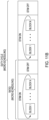
- the blocks may be arranged in sequences. Each sequence may include block sequence elements such as block list, ratio, duty cycle, fields list, frequency (such as CR frequency), and repeat count.
- the block list may be an array of blocks.
- the ratio may be a block on/off ratio. The ratio may be referred to as micro-scheduling.
- the duty cycle may be the duration of the block ratio in minutes.
- the duty cycle may also be referred to as macro-scheduling.
- the field list may list possible electrode settings including fractionalization data.
- the frequency may be the frequency to repeat the electrode field combinations.
- the repeat count may be the number of times to repeat the sequence.
- FIG. 11B illustrates, by way of example and not limitation, micro-scheduling of blocks (Ratio) and macro-scheduling of blocks (Duty Cycle).
- FIG. 11C illustrates, by way of example, phases (Phase0 - Phase6) of the pulse, and the electrodes settings for each pulse to create a field.
- the fields (generated by an electrode setting for a pulse) may be ordered using the CR Field Order. Also illustrated is the order of pulses (electrode field combinations) that may be repeated according to the CR Frequency.
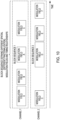
- FIG. 12 is an illustration of a translation from a user-inputted sequence definition 1235 into neuromodulation definition 1236.
- a user interface may be configured to receive user input in order to form the sequence definition.
- the user interface may be configured to enable the user to enter various data that generally correspond to the sequence of blocks and the timing relationships for the blocks.
- the user-inputted data forming the block sequence 1237 may contain user-inputted data for blocks 1238 which may include, by way of example: a list of phases, a duration of the block, a list steering tables (electrode configurations including fractionalized values for active electrodes), a period, a CR field order, and a repeat count for the number of blocks.
- the user-inputted data forming the block sequence 1237 may further include CR Ratio, CR Duty Cycle, CR fields, CR frequency and Repeat count.
- the neuromodulation definition 1236 contains information from the sequence definition 1235 after translation into assembly language.
- the neuromodulation definition 1236 may include program information 1239, firmware block of instructions 1240, firmware instruction information 1241 and a firmware instruction data table1242.
- the program information 1239 may provide: a list of firmware instructions or blocks of instructions; an initialization block, a list of function tables, a list of CR steering tables, a CR index table for use to index into the CR steering tables, and a repeat count.
- the firmware block of instructions may include: stimulator register settings for this block; begin instruction; list of instructions to set the corresponding register; list of optimized instructions which are instructions that optimize the list of instructions to minimize memory usage; and end instruction.
- the firmware instruction may include OpCode which specifies the operation to be performed such as setting a register, staring a stimulation, and looping.
- the firmware instruction may include a list of fields, an event time, and a function label.
- the firmware instruction table may include a label, a data segment type, a coefficient format type, a list of unsigned short data, and associated stimulator register information.
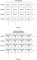
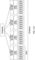
- FIG. 13 illustrates, by way of example and not limitation, tables containing spatially-different modulation fields where each row includes data for sequence of neuromodulation fields, and further includes an index table for use to identify a pointer to the tables.
- the program information may provide a list of CR steering tables, and a CR index table for use to index into the CR steering tables.
- the neuromodulator has a plurality of registers for storing neuromodulation parameter data. An individual one of these registers may be configured to store neuromodulation parameter data for at least one of the plurality of electrodes.
- the programming system may include a plurality of field order tables corresponding to the plurality of registers. Each of the plurality of tables may contain settings for a respective one of the plurality of registers.
- Each of the plurality of field order tables include a plurality of rows and a plurality of columns.
- the plurality of rows corresponds to a plurality of block sequences, respectively, to define field order settings.
- the illustrated table provides a row for the possible permutations for ordering four distinct fields (labeled Field 1, Field2, Field 3 and Field 4).
- each of the plurality of rows may correspond to the register data for a single register, which may contain register data for two of the plurality of electrodes.
- the CR index table 1344 (also referenced as LOAD AFT ABLEIND TABLE) may be populated to produce a sequence of desired field combinations, such as pseudo random field sequences.
- the translator may be configured to use the block sequence descriptions to determine one of the pointers for use to identify a row in the field order tables for use to load neuromodulation data from that row into one of the plurality of registers.
- a pointer may be selected for use to select a row in the steering table to provide the desired sequence of fields for a register.
- the register may be a 16 bit register, and may contain data for two electrodes (8 bits per electrode) in the electrode array.
- FIG. 13 illustrates an example where a sequence of data from the Index table 1344 (0x0078; 0x0090; 0x0040 ...) are used to index into Row 78 (0x978), Row 90 (0x990) and Row 40 (0x940) of the CR Steering tables 1343.
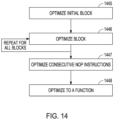
- FIG. 14 illustrates an example of a process to optimize the blocks for transmitting and storing register data.
- the programmer system may optimize the instructions to update multiple Application Specific Integrated Circuit (ASIC) register settings at the same time and to minimize memory usage. Optimization may be performed starting with an initial block 1445, and then performing a block-by-block optimization for all blocks in the sequence 1446. Once all blocks are optimized then it is determined if there are consecutive no operation blocks that can be combined to a single block (e.g. 1447) and determined if blocks can be optimized to a function 1448 (e.g. a function in the function tables within the program, as illustrated in FIG. 13 ).
- ASIC Application Specific Integrated Circuit
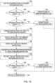
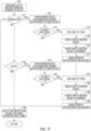
- FIG. 15 illustrates an example of a process for optimizing an instruction or block of instructions.
- the block or instructions are copied to optimized block/instructions. If at 1550 the optimized instruction count is 0, then the block is converted to a signal NOP instruction 1551. If at 1552 the optimized instruction count is 1, then the block is converted to a single instruction. If the optimized instruction count is not 0 and is not 1, then the process may continue at 1554 to combine instructions that write to the same register address. The process may continue at 1555 to create a block with the combined register address instructions. Any duplicate combined instructions may be removed at 1556.
- multiple Set Register instructions may be converted to a single SetMultiReg instruction. As illustrated at 1558, only the last instruction may be set to be a StimUpdate instruction. If at 1559, the Optimized instruction count is 1, then the block may be converted to a single instruction. Otherwise, the process may return the optimized block 1561.
- FIG. 16 illustrates an example of a process for optimizing consecutive NOP instructions.
- the process may initialize the instruction to delete list; and at 1663, the process may initialize multiple set Reg Data segment table.
- the instruction type is determined.
- the number of future consecutive NOP instructions and totalEvent is determined. If at 1666 the total number of consecutive NOP instructions is greater than 1, then the process may modify the NOP instruction event time to consecutive total event time 1667, and may add NOP instruction indices to the Instruction To Delete list 1668.
- the process steps 1664-1668 may be repeated for all instructions / blocks in the sequence.
- the instructions that were combined into one NOP instruction maybe deleted.
- FIG. 17 illustrates an example of a process for optimizing a series of instructions to a single Function instruction.
- the process may initialize a list of instructions / block numbers to delete. If instructions are to be deleted at 1771, the process proceeds to 1772 to look ahead from the current block and convert instructions to table of data. If at 1773 the table data count is greater than 3, then a label is added to the table 1774, an apply function block is created 1775, an apply function block is inserted into the program 1776, and converted instructions are marked to be deleted 1777. Similarly, if instructions are to be deleted at 1778, the process proceeds to 1779 to look ahead from the current block and convert instructions to table of data.
- Method examples described herein may be machine or computer-implemented at least in part. Some examples may include a computer-readable medium or machine-readable medium encoded with instructions operable to configure an electronic device to perform methods as described in the above examples.
- An implementation of such methods may include code, such as microcode, assembly language code, a higher-level language code, or the like. Such code may include computer readable instructions for performing various methods. The code may form portions of computer program products. Further, in an example, the code may be tangibly stored on one or more volatile, non-transitory, or non-volatile tangible computer-readable media, such as during execution or at other times.
- Examples of these tangible computer-readable media may include, but are not limited to, hard disks, removable magnetic disks, removable optical disks (e.g., compact disks and digital video disks), magnetic cassettes, memory cards or sticks, random access memories (RAMs), read only memories (ROMs), and the like.
Landscapes
- Health & Medical Sciences (AREA)
- Engineering & Computer Science (AREA)
- Biomedical Technology (AREA)
- General Health & Medical Sciences (AREA)
- Public Health (AREA)
- Life Sciences & Earth Sciences (AREA)
- Veterinary Medicine (AREA)
- Animal Behavior & Ethology (AREA)
- Radiology & Medical Imaging (AREA)
- Nuclear Medicine, Radiotherapy & Molecular Imaging (AREA)
- Neurology (AREA)
- Neurosurgery (AREA)
- Human Computer Interaction (AREA)
- Physics & Mathematics (AREA)
- Computer Networks & Wireless Communication (AREA)
- Signal Processing (AREA)
- Acoustics & Sound (AREA)
- Epidemiology (AREA)
- Medical Informatics (AREA)
- Business, Economics & Management (AREA)
- General Business, Economics & Management (AREA)
- Primary Health Care (AREA)
- Electrotherapy Devices (AREA)
- Micro-Organisms Or Cultivation Processes Thereof (AREA)
- Saccharide Compounds (AREA)
Claims (15)
- System (100; 300; 500), aufweisend:einen Neuromodulator (102; 302; 502), wobei der Neuromodulator einen Neuromodulationsgenerator und mehrere Elektroden (101; 301; 501) aufweist, die dazu eingerichtet sind, mindestens zwei Neuromodulationsorten Neuromodulation unter Verwendung von mindestens zwei Zeitkanälen zuzuführen; undein Programmierungssystem (103; 303; 503), das dazu eingerichtet ist, mit dem Neuromodulator drahtlos zu kommunizieren, wobei das Programmierungssystem eine Nutzerschnittstelle aufweist, wobei das Programmierungssystem dazu eingerichtet ist, über die Nutzerschnittstelle eine Nutzereingabe zu empfangen zur Verwendung bei der Programmierung von mindestens zwei Zeitkanälen, um Sequenzen von räumlich unterschiedlichen Neuromodulationsfeldern für jeweils die mindestens zwei Neuromodulation zu erzeugen,wobei für jeden der mindestens zwei Zeitkanäle die Programmierung das Erzeugen von Blocksequenzbeschreibungen umfasst, um für den entsprechenden der mindestens zwei Zeitkanäle sowohl eine Sequenz von Blöcken als auch Zeitbeziehungen zwischen den Blöcken zu definieren,wobei jeder der Blöcke einem Neuromodulationsparametersatz einer entsprechenden Elektrodenkonfiguration entspricht, um ein entsprechendes der räumlich unterschiedlichen Neuromodulationsfelder zu erzeugen, undwobei das Programmierungssystem (103; 303; 503) dazu eingerichtet ist, die Blocksequenzbeschreibungen in Neuromodulator-Befehle zu übersetzen und die Neuromodulator-Befehle an den Neuromodulator drahtlos zu kommunizieren, damit sie von dem Neuromodulator verwendet werden, um jedem der mindestens zwei Neuromodulationsorte die Neuromodulation unter Verwendung des entsprechenden Zeitkanals gemäß der entsprechenden Blocksequenzbeschreibung zuzuführen.
- System nach Anspruch 1, wobei das Programmierungssystem (103; 303; 503) ferner einen Übersetzer (519) und einen Assembler (520) aufweist, wobei der Übersetzer dazu eingerichtet ist, die Blocksequenzbeschreibung in Assemblersprache zu übersetzen und der Assembler dazu eingerichtet ist, die Assemblersprache in Neuromodulator-Befehle zu übersetzen.
- System nach Anspruch 2, wobei der Übersetzer (519) dazu eingerichtet ist, gleichzeitig die Blöcke zur Aktualisierung von Registereinstellungen zu optimieren und Speichernutzung zu minimieren, und dann zu bestimmen, ob es aufeinanderfolgende Keine-Aktion-Blöcke gibt, die zu einem einzigen Block zusammengefasst werden können, und/oder ob Blöcke zu einer Funktion optimiert werden können.
- System nach einem der Ansprüche 1 bis 3, wobei die drahtlos kommunizierten Neuromodulator-Befehle Bytes aufweisen, die Energiefraktionen, die einzelnen der mehreren Elektroden (101; 301; 501) zugewiesen sind, entsprechen, und die Bytes in Registern des Neuromodulators gespeichert sind, um von dem Neuromodulator verwendet zu werden, um den einzelnen der mehreren Elektroden (101; 301; 501) Energie zuzuweisen.
- System nach Anspruch 4, wobei der Neuromodulationsgenerator mehrere unabhängige Stromquellen für jeweils die mehreren Elektroden (101; 301; 501) aufweist, und die Bytes, die den Energiefraktionen, die einzelnen der mehreren Elektroden (101; 301; 501) zugewiesen sind, entsprechen, von den unabhängigen Stromquellen verwendet werden, um Stromamplituden für die einzelnen der mehreren Elektroden (101; 301; 501) zu erzeugen.
- System nach einem der Ansprüche 1 bis 5, wobei die Blöcke in der Blocksequenz unterschiedlichen Elektrodenkonfigurationen entsprechen, um eine Sequenz von räumlich unterschiedlichen Modulationsfeldern zu erzeugen.
- System nach einem der Ansprüche 1 bis 6, wobei die Nutzereingabe, die die Blocksequenz definiert, eine Nutzereingabe aufweist, um Blöcke für die Blocksequenz auszuwählen und zu ordnen.
- System nach einem der Ansprüche 1 bis 7, wobei die Blocksequenz OFF-Blöcke aufweist, für die keine Neuromodulation vorgesehen ist.
- System nach einem der Ansprüche 1 bis 8, wobei jedem der Blöcke eine Amplitude, Pulsbreite und -rate zugordnet sind.
- System nach einem der Ansprüche 1 bis 9, wobei Nutzereingaben, die die Zeitbeziehungen definieren, aufweisen:Interblock-Zeiten zwischen Blöcken in der Blocksequenz; und/odereine Dauer, einen Startzeitpunkt oder einen Stoppzeitpunkt für Blöcke in der Blocksequenz.
- System nach einem der Ansprüche 1 bis 10, wobei die Blocksequenz wiederholt wird und mit einem ON-OFF-Arbeitszyklus verknüpft ist, der eine ON-Zeit zum Wiederholen der Blocksequenz und eine OFF-Zeit aufweist.
- System nach einem der Ansprüche 1 bis 11, wobei:der Neuromodulator mehrere Register zum Speichern von Neuromodulationsparameterdaten aufweist, wobei ein einzelnes der mehreren Register dazu eingerichtet ist, Neuromodulationsparameterdaten für mindestens eine der mehreren Elektroden (101; 301; 501) zu speichern;das Programmierungssystem (103; 303; 503) mehrere Feldordnungstabellen aufweist, die den mehreren Registern entsprechen; undjede der mehreren Tabellen Einstellungen für ein jeweiliges der mehreren Register enthält.
- System nach Anspruch 12, wobei:jede der mehreren Feldordnungstabellen mehrere Reihen und mehrere Spalten aufweist; unddie mehreren Reihen jeweils mehreren Blocksequenzen entsprechen, um Feldordnung-Einstellungen zu definieren.
- System nach Anspruch 13, wobei jede der mehreren Reihen den Registerdaten für zwei der mehreren Elektroden (101; 301; 501) entspricht.
- System nach einem der Ansprüche 12 bis 14, wobei das System dazu eingerichtet ist, die Blocksequenzbeschreibung in Assemblersprache und eine Indextabelle zu übersetzen, die Zeiger zu den mehreren Reihen in der Feldordnungstabelle enthält, wobei das System dazu eingerichtet ist, die Blocksequenzbeschreibungen zu verwenden, um einen der Zeiger zu bestimmen, der zur Bestimmung der Einstellungen für das jeweilige eine der mehreren Register zu verwenden ist.
Applications Claiming Priority (2)
| Application Number | Priority Date | Filing Date | Title |
|---|---|---|---|
| US202163149570P | 2021-02-15 | 2021-02-15 | |
| PCT/US2022/016325 WO2022174149A1 (en) | 2021-02-15 | 2022-02-14 | Systems and methods for programming neuromodulation sequences |
Publications (2)
| Publication Number | Publication Date |
|---|---|
| EP4291293A1 EP4291293A1 (de) | 2023-12-20 |
| EP4291293B1 true EP4291293B1 (de) | 2024-12-25 |
Family
ID=80625399
Family Applications (1)
| Application Number | Title | Priority Date | Filing Date |
|---|---|---|---|
| EP22707567.8A Active EP4291293B1 (de) | 2021-02-15 | 2022-02-14 | Systeme zur programmierung von neuromodulationssequenzen |
Country Status (4)
| Country | Link |
|---|---|
| US (1) | US12533521B2 (de) |
| EP (1) | EP4291293B1 (de) |
| AU (1) | AU2022220342B2 (de) |
| WO (1) | WO2022174149A1 (de) |
Cited By (1)
| Publication number | Priority date | Publication date | Assignee | Title |
|---|---|---|---|---|
| US12533521B2 (en) | 2021-02-15 | 2026-01-27 | Boston Scientific Neuromodulation Corporation | Systems and methods for programming neuromodulation sequences |
Families Citing this family (5)
| Publication number | Priority date | Publication date | Assignee | Title |
|---|---|---|---|---|
| US11925805B2 (en) | 2017-01-18 | 2024-03-12 | Soin Neuroscience, LLC | Tunable electrical noise signal technologies |
| US11793443B2 (en) | 2022-02-01 | 2023-10-24 | Soin Neuroscience, LLC | Adjustable random electrical stimulation technologies |
| US12279871B2 (en) * | 2022-11-09 | 2025-04-22 | Soin Neuroscience, LLC | Electrode array for spatially random electrical stimulation |
| US11964155B1 (en) | 2023-07-14 | 2024-04-23 | Soin Neuroscience, LLC | Rapid frequency cycling during electrical stimulation |
| US20260041918A1 (en) * | 2024-08-09 | 2026-02-12 | Boston Scientific Neuromodulation Corporation | Neuromodulation programming using combined modulation configurations |
Family Cites Families (16)
| Publication number | Priority date | Publication date | Assignee | Title |
|---|---|---|---|---|
| US8620436B2 (en) | 2005-07-08 | 2013-12-31 | Boston Scientific Neuromodulation Corporation | Current generation architecture for an implantable stimulator device having coarse and fine current control |
| GB2473163B (en) | 2008-06-25 | 2012-07-18 | Advanced Neuromodulation Sys | A system for electrically stimulating tissue of a patient by shifting a locus of stimulaton |
| US8412345B2 (en) | 2009-11-03 | 2013-04-02 | Boston Scientific Neuromodulation Corporation | System and method for mapping arbitrary electric fields to pre-existing lead electrodes |
| US9446231B2 (en) | 2009-11-23 | 2016-09-20 | Boston Scientific Neuromodulation Corporation | Neurostimulation system and method for compounding current to minimize current sources |
| AU2010336976B2 (en) | 2009-12-30 | 2015-08-27 | Boston Scientific Neuromodulation Corporation | System for independently operating multiple neurostimulation channels |
| US8909350B2 (en) | 2011-03-15 | 2014-12-09 | Boston Scientific Neuromodulation Corporation | Neurostimulation system for defining a generalized ideal multipole configuration |
| US9021454B2 (en) * | 2012-11-08 | 2015-04-28 | Unisys Corpoation | Operand and limits optimization for binary translation system |
| EP3148639A4 (de) * | 2014-05-17 | 2018-04-18 | Cerevast Medical Inc. | Verfahren und vorrichtungen zur anwendung von gesamtwellenformen mit transdermaler neurostimulation |
| US10456583B2 (en) * | 2016-06-02 | 2019-10-29 | Boston Scientific Neuromodulation Corporation | Customized priming by neuromodulation device |
| US10632300B2 (en) * | 2016-09-10 | 2020-04-28 | Boston Scientific Neuromodulation Corporation | Measurement circuitry for measuring analog values in an implantable pulse generator |
| US10617872B2 (en) | 2016-11-23 | 2020-04-14 | Boston Scientific Neuromodulation Corporation | Systems and methods for programming neuromodulation therapy |
| EP3565462B1 (de) * | 2017-01-05 | 2021-05-12 | California Institute of Technology | Dueling-bandits-algorithmus für die neuromodulationstherapie |
| US20180214699A1 (en) * | 2017-02-01 | 2018-08-02 | Boston Scientific Neuromodulation Corporation | Stimulation field templates to be applied across patient populations |
| US11911620B2 (en) * | 2019-07-22 | 2024-02-27 | Ismail Mohammed Yousif Musallam | Neuromodulation for treatment of brain and eye strokes and/or acute dysregulated reduced cerebral or ocular blood flow |
| EP3827875B1 (de) * | 2019-11-27 | 2023-07-05 | ONWARD Medical N.V. | Neuromodulationssystem |
| EP4291293B1 (de) | 2021-02-15 | 2024-12-25 | Boston Scientific Neuromodulation Corporation | Systeme zur programmierung von neuromodulationssequenzen |
-
2022
- 2022-02-14 EP EP22707567.8A patent/EP4291293B1/de active Active
- 2022-02-14 US US17/671,267 patent/US12533521B2/en active Active
- 2022-02-14 AU AU2022220342A patent/AU2022220342B2/en active Active
- 2022-02-14 WO PCT/US2022/016325 patent/WO2022174149A1/en not_active Ceased
Cited By (1)
| Publication number | Priority date | Publication date | Assignee | Title |
|---|---|---|---|---|
| US12533521B2 (en) | 2021-02-15 | 2026-01-27 | Boston Scientific Neuromodulation Corporation | Systems and methods for programming neuromodulation sequences |
Also Published As
| Publication number | Publication date |
|---|---|
| US12533521B2 (en) | 2026-01-27 |
| AU2022220342A1 (en) | 2023-09-28 |
| EP4291293A1 (de) | 2023-12-20 |
| WO2022174149A1 (en) | 2022-08-18 |
| US20220257957A1 (en) | 2022-08-18 |
| AU2022220342B2 (en) | 2025-05-01 |
Similar Documents
| Publication | Publication Date | Title |
|---|---|---|
| EP4291293B1 (de) | Systeme zur programmierung von neuromodulationssequenzen | |
| AU2020289746B2 (en) | Neuromodulation using stochastically-modulated stimulation parameters | |
| EP3256206B1 (de) | System zur bestimmung der neurologischen position epiduraler elektroden | |
| CN107073269B (zh) | 用于编程复杂神经刺激模式的方法和装置 | |
| EP3528890B1 (de) | Neuromodulationssystem zur erzeugung von mehrphasigen feldern | |
| EP2686063B1 (de) | Nervenstimulationssystem zur definition einer verallgemeinerten idealen mehrpoligen konfiguration | |
| US10617871B2 (en) | Spinal cord stimulation accounting for different entry angles of root fibers | |
| EP3389772B1 (de) | Programmiertechniken zur elektrischen stimulation | |
| US20150088228A1 (en) | Neurostimulation system for selectively estimating volume of activation and providing therapy | |
| US11590350B2 (en) | Systems and methods for delivering spinal cord stimulation therapy | |
| US20240408397A1 (en) | Systems and methods for spectrally banded neuromodulation | |
| US20250262440A1 (en) | Systems and methods for providing dynamic neurostimulation | |
| US20250025699A1 (en) | Systems and methods with activating recharge stimulation | |
| US20250256110A1 (en) | Systems and methods for electrical spatial field for lead implant |
Legal Events
| Date | Code | Title | Description |
|---|---|---|---|
| STAA | Information on the status of an ep patent application or granted ep patent |
Free format text: STATUS: UNKNOWN |
|
| STAA | Information on the status of an ep patent application or granted ep patent |
Free format text: STATUS: THE INTERNATIONAL PUBLICATION HAS BEEN MADE |
|
| PUAI | Public reference made under article 153(3) epc to a published international application that has entered the european phase |
Free format text: ORIGINAL CODE: 0009012 |
|
| STAA | Information on the status of an ep patent application or granted ep patent |
Free format text: STATUS: REQUEST FOR EXAMINATION WAS MADE |
|
| 17P | Request for examination filed |
Effective date: 20230914 |
|
| AK | Designated contracting states |
Kind code of ref document: A1 Designated state(s): AL AT BE BG CH CY CZ DE DK EE ES FI FR GB GR HR HU IE IS IT LI LT LU LV MC MK MT NL NO PL PT RO RS SE SI SK SM TR |
|
| DAV | Request for validation of the european patent (deleted) | ||
| DAX | Request for extension of the european patent (deleted) | ||
| GRAP | Despatch of communication of intention to grant a patent |
Free format text: ORIGINAL CODE: EPIDOSNIGR1 |
|
| STAA | Information on the status of an ep patent application or granted ep patent |
Free format text: STATUS: GRANT OF PATENT IS INTENDED |
|
| INTG | Intention to grant announced |
Effective date: 20240718 |
|
| GRAS | Grant fee paid |
Free format text: ORIGINAL CODE: EPIDOSNIGR3 |
|
| GRAF | Information related to payment of grant fee modified |
Free format text: ORIGINAL CODE: EPIDOSCIGR3 |
|
| GRAA | (expected) grant |
Free format text: ORIGINAL CODE: 0009210 |
|
| STAA | Information on the status of an ep patent application or granted ep patent |
Free format text: STATUS: THE PATENT HAS BEEN GRANTED |
|
| AK | Designated contracting states |
Kind code of ref document: B1 Designated state(s): AL AT BE BG CH CY CZ DE DK EE ES FI FR GB GR HR HU IE IS IT LI LT LU LV MC MK MT NL NO PL PT RO RS SE SI SK SM TR |
|
| REG | Reference to a national code |
Ref country code: GB Ref legal event code: FG4D |
|
| REG | Reference to a national code |
Ref country code: CH Ref legal event code: EP |
|
| REG | Reference to a national code |
Ref country code: DE Ref legal event code: R096 Ref document number: 602022009110 Country of ref document: DE |
|
| REG | Reference to a national code |
Ref country code: IE Ref legal event code: FG4D |
|
| REG | Reference to a national code |
Ref country code: NL Ref legal event code: FP |
|
| REG | Reference to a national code |
Ref country code: LT Ref legal event code: MG9D |
|
| PG25 | Lapsed in a contracting state [announced via postgrant information from national office to epo] |
Ref country code: HR Free format text: LAPSE BECAUSE OF FAILURE TO SUBMIT A TRANSLATION OF THE DESCRIPTION OR TO PAY THE FEE WITHIN THE PRESCRIBED TIME-LIMIT Effective date: 20241225 |
|
| PG25 | Lapsed in a contracting state [announced via postgrant information from national office to epo] |
Ref country code: FI Free format text: LAPSE BECAUSE OF FAILURE TO SUBMIT A TRANSLATION OF THE DESCRIPTION OR TO PAY THE FEE WITHIN THE PRESCRIBED TIME-LIMIT Effective date: 20241225 |
|
| PG25 | Lapsed in a contracting state [announced via postgrant information from national office to epo] |
Ref country code: BG Free format text: LAPSE BECAUSE OF FAILURE TO SUBMIT A TRANSLATION OF THE DESCRIPTION OR TO PAY THE FEE WITHIN THE PRESCRIBED TIME-LIMIT Effective date: 20241225 |
|
| PG25 | Lapsed in a contracting state [announced via postgrant information from national office to epo] |
Ref country code: NO Free format text: LAPSE BECAUSE OF FAILURE TO SUBMIT A TRANSLATION OF THE DESCRIPTION OR TO PAY THE FEE WITHIN THE PRESCRIBED TIME-LIMIT Effective date: 20250325 |
|
| PG25 | Lapsed in a contracting state [announced via postgrant information from national office to epo] |
Ref country code: LV Free format text: LAPSE BECAUSE OF FAILURE TO SUBMIT A TRANSLATION OF THE DESCRIPTION OR TO PAY THE FEE WITHIN THE PRESCRIBED TIME-LIMIT Effective date: 20241225 Ref country code: GR Free format text: LAPSE BECAUSE OF FAILURE TO SUBMIT A TRANSLATION OF THE DESCRIPTION OR TO PAY THE FEE WITHIN THE PRESCRIBED TIME-LIMIT Effective date: 20250326 |
|
| PGFP | Annual fee paid to national office [announced via postgrant information from national office to epo] |
Ref country code: AT Payment date: 20250417 Year of fee payment: 4 |
|
| PG25 | Lapsed in a contracting state [announced via postgrant information from national office to epo] |
Ref country code: RS Free format text: LAPSE BECAUSE OF FAILURE TO SUBMIT A TRANSLATION OF THE DESCRIPTION OR TO PAY THE FEE WITHIN THE PRESCRIBED TIME-LIMIT Effective date: 20250325 |
|
| REG | Reference to a national code |
Ref country code: AT Ref legal event code: MK05 Ref document number: 1753685 Country of ref document: AT Kind code of ref document: T Effective date: 20241225 |
|
| PG25 | Lapsed in a contracting state [announced via postgrant information from national office to epo] |
Ref country code: SM Free format text: LAPSE BECAUSE OF FAILURE TO SUBMIT A TRANSLATION OF THE DESCRIPTION OR TO PAY THE FEE WITHIN THE PRESCRIBED TIME-LIMIT Effective date: 20241225 |
|
| PG25 | Lapsed in a contracting state [announced via postgrant information from national office to epo] |
Ref country code: PL Free format text: LAPSE BECAUSE OF FAILURE TO SUBMIT A TRANSLATION OF THE DESCRIPTION OR TO PAY THE FEE WITHIN THE PRESCRIBED TIME-LIMIT Effective date: 20241225 |
|
| PG25 | Lapsed in a contracting state [announced via postgrant information from national office to epo] |
Ref country code: ES Free format text: LAPSE BECAUSE OF FAILURE TO SUBMIT A TRANSLATION OF THE DESCRIPTION OR TO PAY THE FEE WITHIN THE PRESCRIBED TIME-LIMIT Effective date: 20241225 |
|
| PG25 | Lapsed in a contracting state [announced via postgrant information from national office to epo] |
Ref country code: IS Free format text: LAPSE BECAUSE OF FAILURE TO SUBMIT A TRANSLATION OF THE DESCRIPTION OR TO PAY THE FEE WITHIN THE PRESCRIBED TIME-LIMIT Effective date: 20250425 |
|
| PG25 | Lapsed in a contracting state [announced via postgrant information from national office to epo] |
Ref country code: PT Free format text: LAPSE BECAUSE OF FAILURE TO SUBMIT A TRANSLATION OF THE DESCRIPTION OR TO PAY THE FEE WITHIN THE PRESCRIBED TIME-LIMIT Effective date: 20250428 |
|
| PG25 | Lapsed in a contracting state [announced via postgrant information from national office to epo] |
Ref country code: EE Free format text: LAPSE BECAUSE OF FAILURE TO SUBMIT A TRANSLATION OF THE DESCRIPTION OR TO PAY THE FEE WITHIN THE PRESCRIBED TIME-LIMIT Effective date: 20241225 |
|
| PG25 | Lapsed in a contracting state [announced via postgrant information from national office to epo] |
Ref country code: AT Free format text: LAPSE BECAUSE OF FAILURE TO SUBMIT A TRANSLATION OF THE DESCRIPTION OR TO PAY THE FEE WITHIN THE PRESCRIBED TIME-LIMIT Effective date: 20241225 Ref country code: RO Free format text: LAPSE BECAUSE OF FAILURE TO SUBMIT A TRANSLATION OF THE DESCRIPTION OR TO PAY THE FEE WITHIN THE PRESCRIBED TIME-LIMIT Effective date: 20241225 |
|
| PG25 | Lapsed in a contracting state [announced via postgrant information from national office to epo] |
Ref country code: SK Free format text: LAPSE BECAUSE OF FAILURE TO SUBMIT A TRANSLATION OF THE DESCRIPTION OR TO PAY THE FEE WITHIN THE PRESCRIBED TIME-LIMIT Effective date: 20241225 |
|
| PG25 | Lapsed in a contracting state [announced via postgrant information from national office to epo] |
Ref country code: CZ Free format text: LAPSE BECAUSE OF FAILURE TO SUBMIT A TRANSLATION OF THE DESCRIPTION OR TO PAY THE FEE WITHIN THE PRESCRIBED TIME-LIMIT Effective date: 20241225 |
|
| PG25 | Lapsed in a contracting state [announced via postgrant information from national office to epo] |
Ref country code: IT Free format text: LAPSE BECAUSE OF FAILURE TO SUBMIT A TRANSLATION OF THE DESCRIPTION OR TO PAY THE FEE WITHIN THE PRESCRIBED TIME-LIMIT Effective date: 20241225 |
|
| PG25 | Lapsed in a contracting state [announced via postgrant information from national office to epo] |
Ref country code: SE Free format text: LAPSE BECAUSE OF FAILURE TO SUBMIT A TRANSLATION OF THE DESCRIPTION OR TO PAY THE FEE WITHIN THE PRESCRIBED TIME-LIMIT Effective date: 20241225 |
|
| PG25 | Lapsed in a contracting state [announced via postgrant information from national office to epo] |
Ref country code: MC Free format text: LAPSE BECAUSE OF FAILURE TO SUBMIT A TRANSLATION OF THE DESCRIPTION OR TO PAY THE FEE WITHIN THE PRESCRIBED TIME-LIMIT Effective date: 20241225 |
|
| REG | Reference to a national code |
Ref country code: DE Ref legal event code: R097 Ref document number: 602022009110 Country of ref document: DE |
|
| REG | Reference to a national code |
Ref country code: CH Ref legal event code: PL |
|
| PG25 | Lapsed in a contracting state [announced via postgrant information from national office to epo] |
Ref country code: DK Free format text: LAPSE BECAUSE OF FAILURE TO SUBMIT A TRANSLATION OF THE DESCRIPTION OR TO PAY THE FEE WITHIN THE PRESCRIBED TIME-LIMIT Effective date: 20241225 |
|
| PG25 | Lapsed in a contracting state [announced via postgrant information from national office to epo] |
Ref country code: LU Free format text: LAPSE BECAUSE OF NON-PAYMENT OF DUE FEES Effective date: 20250214 |
|
| PG25 | Lapsed in a contracting state [announced via postgrant information from national office to epo] |
Ref country code: CH Free format text: LAPSE BECAUSE OF NON-PAYMENT OF DUE FEES Effective date: 20250228 |
|
| PLBE | No opposition filed within time limit |
Free format text: ORIGINAL CODE: 0009261 |
|
| STAA | Information on the status of an ep patent application or granted ep patent |
Free format text: STATUS: NO OPPOSITION FILED WITHIN TIME LIMIT |
|
| 26N | No opposition filed |
Effective date: 20250926 |
|
| REG | Reference to a national code |
Ref country code: BE Ref legal event code: MM Effective date: 20250228 |
|
| PG25 | Lapsed in a contracting state [announced via postgrant information from national office to epo] |
Ref country code: BE Free format text: LAPSE BECAUSE OF NON-PAYMENT OF DUE FEES Effective date: 20250228 |
|
| PGFP | Annual fee paid to national office [announced via postgrant information from national office to epo] |
Ref country code: NL Payment date: 20260121 Year of fee payment: 5 |
|
| PGFP | Annual fee paid to national office [announced via postgrant information from national office to epo] |
Ref country code: GB Payment date: 20260122 Year of fee payment: 5 |
|
| PGFP | Annual fee paid to national office [announced via postgrant information from national office to epo] |
Ref country code: IE Payment date: 20260123 Year of fee payment: 5 Ref country code: DE Payment date: 20260121 Year of fee payment: 5 |
|
| PGFP | Annual fee paid to national office [announced via postgrant information from national office to epo] |
Ref country code: FR Payment date: 20260121 Year of fee payment: 5 |