EP4290796A2 - Kontrollsignalisierung für lotungsreferenzsignal (srb ) - Google Patents
Kontrollsignalisierung für lotungsreferenzsignal (srb ) Download PDFInfo
- Publication number
- EP4290796A2 EP4290796A2 EP23199448.4A EP23199448A EP4290796A2 EP 4290796 A2 EP4290796 A2 EP 4290796A2 EP 23199448 A EP23199448 A EP 23199448A EP 4290796 A2 EP4290796 A2 EP 4290796A2
- Authority
- EP
- European Patent Office
- Prior art keywords
- srs
- type indicator
- transmission
- srs resource
- resource set
- Prior art date
- Legal status (The legal status is an assumption and is not a legal conclusion. Google has not performed a legal analysis and makes no representation as to the accuracy of the status listed.)
- Pending
Links
Images








Classifications
-
- H—ELECTRICITY
- H04—ELECTRIC COMMUNICATION TECHNIQUE
- H04L—TRANSMISSION OF DIGITAL INFORMATION, e.g. TELEGRAPHIC COMMUNICATION
- H04L5/00—Arrangements affording multiple use of the transmission path
- H04L5/003—Arrangements for allocating sub-channels of the transmission path
- H04L5/0048—Allocation of pilot signals, i.e. of signals known to the receiver
- H04L5/0051—Allocation of pilot signals, i.e. of signals known to the receiver of dedicated pilots, i.e. pilots destined for a single user or terminal
-
- H—ELECTRICITY
- H04—ELECTRIC COMMUNICATION TECHNIQUE
- H04B—TRANSMISSION
- H04B7/00—Radio transmission systems, i.e. using radiation field
- H04B7/02—Diversity systems; Multi-antenna system, i.e. transmission or reception using multiple antennas
- H04B7/04—Diversity systems; Multi-antenna system, i.e. transmission or reception using multiple antennas using two or more spaced independent antennas
- H04B7/0413—MIMO systems
- H04B7/0456—Selection of precoding matrices or codebooks, e.g. using matrices antenna weighting
-
- H—ELECTRICITY
- H04—ELECTRIC COMMUNICATION TECHNIQUE
- H04L—TRANSMISSION OF DIGITAL INFORMATION, e.g. TELEGRAPHIC COMMUNICATION
- H04L5/00—Arrangements affording multiple use of the transmission path
- H04L5/0001—Arrangements for dividing the transmission path
- H04L5/0014—Three-dimensional division
- H04L5/0023—Time-frequency-space
-
- H—ELECTRICITY
- H04—ELECTRIC COMMUNICATION TECHNIQUE
- H04L—TRANSMISSION OF DIGITAL INFORMATION, e.g. TELEGRAPHIC COMMUNICATION
- H04L5/00—Arrangements affording multiple use of the transmission path
- H04L5/0091—Signalling for the administration of the divided path, e.g. signalling of configuration information
- H04L5/0094—Indication of how sub-channels of the path are allocated
-
- H—ELECTRICITY
- H04—ELECTRIC COMMUNICATION TECHNIQUE
- H04B—TRANSMISSION
- H04B7/00—Radio transmission systems, i.e. using radiation field
- H04B7/02—Diversity systems; Multi-antenna system, i.e. transmission or reception using multiple antennas
- H04B7/04—Diversity systems; Multi-antenna system, i.e. transmission or reception using multiple antennas using two or more spaced independent antennas
- H04B7/06—Diversity systems; Multi-antenna system, i.e. transmission or reception using multiple antennas using two or more spaced independent antennas at the transmitting station
- H04B7/0686—Hybrid systems, i.e. switching and simultaneous transmission
- H04B7/0695—Hybrid systems, i.e. switching and simultaneous transmission using beam selection
- H04B7/06952—Selecting one or more beams from a plurality of beams, e.g. beam training, management or sweeping
-
- H—ELECTRICITY
- H04—ELECTRIC COMMUNICATION TECHNIQUE
- H04L—TRANSMISSION OF DIGITAL INFORMATION, e.g. TELEGRAPHIC COMMUNICATION
- H04L25/00—Baseband systems
- H04L25/02—Details ; arrangements for supplying electrical power along data transmission lines
- H04L25/0202—Channel estimation
- H04L25/0224—Channel estimation using sounding signals
- H04L25/0226—Channel estimation using sounding signals sounding signals per se
-
- H—ELECTRICITY
- H04—ELECTRIC COMMUNICATION TECHNIQUE
- H04L—TRANSMISSION OF DIGITAL INFORMATION, e.g. TELEGRAPHIC COMMUNICATION
- H04L5/00—Arrangements affording multiple use of the transmission path
- H04L5/0001—Arrangements for dividing the transmission path
- H04L5/0003—Two-dimensional division
- H04L5/0005—Time-frequency
- H04L5/0007—Time-frequency the frequencies being orthogonal, e.g. OFDM(A) or DMT
- H04L5/001—Time-frequency the frequencies being orthogonal, e.g. OFDM(A) or DMT the frequencies being arranged in component carriers
-
- H—ELECTRICITY
- H04—ELECTRIC COMMUNICATION TECHNIQUE
- H04L—TRANSMISSION OF DIGITAL INFORMATION, e.g. TELEGRAPHIC COMMUNICATION
- H04L5/00—Arrangements affording multiple use of the transmission path
- H04L5/0001—Arrangements for dividing the transmission path
- H04L5/0003—Two-dimensional division
- H04L5/0005—Time-frequency
- H04L5/0007—Time-frequency the frequencies being orthogonal, e.g. OFDM(A) or DMT
- H04L5/0012—Hopping in multicarrier systems
Definitions
- wireless cellular communication systems A variety of wireless cellular communication systems have been implemented, including a 3rd Generation Partnership Project (3GPP) Universal Mobile Telecommunications Systems (UMTS) system, a 3GPP Long-Term Evolution (ETE) system, and a 3GPP ETE-Advanced (LTE-A) system.
- 3GPP 3rd Generation Partnership Project
- UMTS Universal Mobile Telecommunications Systems
- ETE 3GPP Long-Term Evolution
- LTE-A 3GPP ETE-Advanced
- Next-generation wireless cellular communication systems based upon ETE and LTE-A systems are being developed, such as a Fifth Generation (5G) wireless system / 5G mobile networks system.
- Next-generation wireless cellular communication systems may provide support for higher bandwidths.
- SRS Sounding Reference Signals
- UE Uplink
- a communication system e.g., a 5G system
- larger bandwidth may be used to increase user data rates and system data rates.
- the mmWave band may be used to provide such wide bandwidth.
- a larger subcarrier spacing may be used in this wideband system. For example, each subcarrier may take 750 kilohertz (kHz).
- Cyclic Prefix (CP) Orthogonal frequency-division multiplexing (OFDM) based waveform may be used for uplink, e.g., if a User Equipment (UE) is not in a coverage limited scenario.
- CP Cyclic Prefix
- OFDM Orthogonal frequency-division multiplexing
- uplink e.g., if a User Equipment (UE) is not in a coverage limited scenario.
- spatial multiplexing may be used for uplink transmission.
- the UE may be able to calculate the precoder based on some downlink reference signal, such as Channel State Information-Reference Signals (CSI-RS), which is also referred to as non-codebook based transmission.
- CSI-RS Channel State Information-Reference Signals
- precoded Sounding Reference Signal may be used, where precoders with different ranks may be used in different SRS resources.
- a gNB may indicate an SRS Resource Indicator (SRI) in the uplink grant.
- SRI SRS Resource Indicator
- the UE may use the same precoder (e.g., the precoder in corresponding precoded SRS) to transmit Physical Uplink Shared Channel (PUSCH) signals.
- PUSCH Physical Uplink Shared Channel
- control signaling enhancement for SRS e.g., to support non-codebook based transmission.
- various embodiments and examples of this disclosure discuss SRS resource grouping, control signaling for precoded SRS, control signaling for non-precoded SRS, etc.
- the UE may transmit multiple one-port precoded SRS resources, where different columns of V may be applied. Then for rank one transmission, the gNB may identify one SRS resource. For transmission involving higher than one rank, the gNB may identify more than one SRS resources. In an example, as the rank may dynamically change, it may be useful for the control signaling to support the indication of different ranks.
- the UE may be able to change the precoder for an SRS resource. Then both the UE and gNB may have the same understanding as to which SRS is identified for a SRI, e.g., to avoid potential Modulation Coding Scheme (MCS) mismatch.
- MCS Modulation Coding Scheme
- phrases “A and/or B” and “A or B” mean (A), (B), or (A and B).
- phrase “A, B, and/or C” means (A), (B), (C), (A and B), (A and C), (B and C), or (A, B and C).
- Processing a transmission may comprise moving the transmission through one or more layers of a protocol stack (which may be implemented in, e.g., hardware and/or software-configured elements), such as by moving a transmission that has been received by an eNB or a UE through one or more layers of a protocol stack.
- a protocol stack which may be implemented in, e.g., hardware and/or software-configured elements
- eNBs and/or UEs discussed below may also generate one or more transmissions of various types. Some generating of a transmission may comprise modulating, encoding, formatting, assembling, and/or otherwise handling a transmission that is to be transmitted. In some embodiments, an eNB or UE generating a transmission may establish the transmission's type and/or a condition associated with the transmission. For some embodiments, an eNB or UE generating a transmission may act in accordance with the transmission's type, and/or may act conditionally based upon the transmission's type. An eNB or UE generating a transmission may also determine one or more values or fields of data carried by the transmission.
- multiple SRS resources may be used for precoded SRS.
- the rank is very high, the number of SRS resources may be large. For example, if the maximum rank is assumed to be N, a total of N precoded SRS resources may be needed.
- BPLs Beam Pair Links
- Fig. 1 illustrates an example timing diagram associated with determination of an Uplink (UL) precoder, based on exchange of various types of SRS resource sets between a gNB 110 and a UE 120, according to some embodiments.
- the gNB 110 may issue a trigger for SRS for Beam Management (BM).
- the trigger for SRS for BM may be issued through higher level signaling, such as a Radio Resource Control (RRC) message, or through Downlink Control Information (DCI).
- RRC Radio Resource Control
- DCI Downlink Control Information
- the UE 120 may transmit an SRS for BM.
- the SRS for BM may be used (e.g., by the gNB 110) to find out possible BPL(s) (e.g., an optimal, near optimal, or best BPL(s)), illustrated as operation 134 in Fig. 1 .
- BPL(s) e.g., an optimal, near optimal, or best BPL(s)
- the gNB 110 may issue a trigger for non-precoded SRS.
- the trigger for non-precoded SRS may be issued through higher level signaling, such as an RRC message, or DCI.
- the UE 120 may transmit a non-precoded SRS.
- the non-precoded SRS may be used (e.g., by the gNB 110) to find out the possible maximum rank of precoder (e.g., determine possible maximum Rank Indicator (RI)), illustrated as operation 140 in Fig. 1 .
- the possible maximum rank of precoder e.g., determine possible maximum Rank Indicator (RI)
- the gNB 110 may update SRS resource setting for pre-coded SRS, and may issue a trigger for precoded SRS at 142.
- the trigger for precoded SRS may be issued through higher level signaling, such as an RRC message, or DCI.
- the UE 120 may determine the precoder, based at least in part on the maximum possible RI and measurements of CSI-RS.
- the UE 120 may transmit a precoded SRS to the gNB 110.
- the gNB may determine MCS and RI, and at 150 the gNB 110 may transmit a UL grant along with SRI and the MCS.
- the UE 120 may transmit PUSCH signals, based on the UL grant.
- joint non-precoded and precoded SRS resources may be used.
- the possible BPLs may be selected from the SRS for beam management (e.g., at 134); in a second operation, the maximum possible rank of the precoder may be determined based on the non-precoded SRS (e.g., at 140); and in a third operation, the precoded SRS may be used to determine MCS (e.g., at 148).
- MCS e.g., at 148
- three SRS resource groups may be used: (i) SRS resource group 1: SRS for BM (e.g., which may be used to find out possible BPL(s)), (ii) SRS resource group 2: non-precoded SRS (e.g., which may be used to determine the maximum possible rank), and (iii) SRS resource group 3: precoded SRS (e.g., which is used to determine the precoder, MCS, RI).
- a maximum number of SRS resource may be equal to (N beam ⁇ N panel ), where N beam may indicate a number of transmit (Tx) beams and N panel may denote a number of panels.
- SRS resource group 2 e.g., non-precoded SRS
- a number of SRS resources may be equal to N BPL , where N BPL may refer to the number of BPLs (e.g., as determined at 134 of Fig. 1 ).
- a number of SRS resources may be equal to (N RI ⁇ N BPL ), where N RI may be the maximum possible rank of precoder.
- the number of SRS resources in the SRS resource group 3 may be used to determine a payload size of SRI in an uplink grant (e.g., the size of SRI in the UL grant at 150).
- an SRS type indicator (e.g., which may indicate the group number) may be configured by the gNB 110 using higher layer signaling (e.g., RRC message).
- the SRS type indicator may comprise two bits. Table 1 below illustrates example values for the SRS type indicator (the values of the SRS type indicator and the corresponding indication in Table 1 are mere examples, and do not limit the scope of this disclosure).
- an active SRS group index may be used to indicate whether a current transmission scheme is codebook based transmission, or non-codebook based transmission scheme. For example, if the active SRS group index is for non-precoded SRS, then the codebook based transmission scheme may be assumed. If the active SRS group index is for precoded SRS, then non-codebook based transmission scheme may be assumed. In an example, the active SRS group index may be configured by higher layer signaling or DCI. The active SRS group index may be panel specific (e.g., individual panel may have a corresponding active SRS group index), or may be common for more than one panel (e.g., common for all panels). In an example, the payload size of SRI may be determined by the active SRS group index.
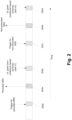
- Fig. 2 illustrates a transmission scheme switching between various SRS resource groups, according to some embodiments.
- Fig. 2 illustrates various transmission slots, such as UL transmission slots 204a, 204b, and Downlink (DL) transmission slots 202a, 202b, 202c, and 202d.
- the transmission slots progress from 202a, 204a, 202b, and so on, with time, as illustrated in the figure.
- the SRS group index (e.g., which may be the SRS type indicator of Table 1 in an example) may be indicated by the higher layer signaling or DCI.
- the UE e.g., UE 120
- the UE may select corresponding types of SRS to transmit.
- the transmission scheme for the UL grant at 202b may be based on SRS group index of the latest successfully transmitted SRS.
- the latest successfully transmitted SRS is at 204a, and the corresponding group index (which was included in the trigger at 202a) indicates that the latest successfully transmitted SRS is for precoded SRS.
- the UL grant may indicate a non-codebook based transmission scheme.
- the transmission scheme indicated in a UL grant may be determined by SRS group index of the latest successfully transmitted SRS, as discussed with respect to Fig. 2 .
- the UL grants at 202b and 202d may include corresponding SRIs. Assume that the UL grant at 202b be at slot n1, and the UL grant at 202d be at slot n2. Thus, at slot n1, the corresponding SRI is associated with the most recent transmission of the SRS resource identified by the SRI (e.g., SRS resource of 204a). Similarly, at slot n2, the corresponding SRI is associated with the most recent transmission of the SRS resource identified by the SRI (e.g., SRS resource of 204b).
- a UE may apply different rank 1 precoders in different SRS resources (e.g., apply a first rank 1 precoder for first SRS resource, apply a first rank 2 precoder for second SRS resource, etc.).
- some rank 1 precoders may not be idle or appropriate for high rank transmission.
- Fig. 3A illustrates an example UE 320 and examples of precoded SRS resources, where SRS resources 302a and 302b are orthogonal, and SRS resource 304a and 304b are orthogonal, according to some embodiments. In an example, there may be some restrictions for high rank transmission.
- SRS transmissions on the associated set of SRS resource subsets or sets or groups and/or component carriers (CCs) are triggered subject to the detected value.
- a value of 00 for the aperiodic SRS triggering field may indicate that no SRS transmission is triggered.
- a value of 01 for the aperiodic SRS triggering field may indicate that SRS is triggered for a first set of SRS resource subset, SRS resource set, SRS resource group, and/or ⁇ SRS resource subset, CCs set ⁇ and is configured by higher layers, and so on.
- a UE may apply different precoders in different Precoding Resource Block Group (PRG), e.g., to achieve some frequency selective precoding gain (e.g., a first precoder may be used for a first PRG, a second precoder may be used for a second PRG, and so on).
- PRG Precoding Resource Block Group
- the subband SRI(s) may increase the signaling overhead of DCI.
- the subband SRI(s) and wideband SRI(s) may be jointly encoded, e.g., to support dynamic wideband and subband precoding switching. For example, if the SRI(s) for each of multiple subbands are the same, the wideband precoding may be assumed to be similar to the subband SRI(s).
- the number of subbands may be pre-defined, or may be configured by higher layer signaling, or may depend on capabilities of the UE. Table 5 illustrates an example of multiple subband SRI(s) indications, e.g., when a maximum rank is 2 and/or when a number of subband size is 2 (although such a specific number of maximum rank and/or a specific number of subband sizes are merely examples).
- Table 5 is an example for subband SRI(s) indication when maximum rank is 2.
- Table 5 SRI(s) in DCI SRI(s) for subband 1 SRI(s) for subband 2 0 SRS resource 1 SRS resource 1 1 SRS resource 2 SRS resource 2 2 SRS resource 1 SRS resource 2 3 SRS resource 2 SRS resource 1 4 SRS resource 1 and 2 SRS resource 1 and 2 5 SRS resource 3 and 4 SRS resource 3 and 4 6 SRS resource 1 and 2 SRS resource 3 and 4 7 SRS resource 3 and 4 SRS resource 1 and 2
- the uplink grant and subband SRI(s) may be indicated in a two-stage DCI mode.
- the UE may decode the uplink grant first, and may determine the size of another DCI with subband SRI(s). Then the indication of subband SRI(s) may rely on the rank from wideband SRI(s). If the DCI for subband SRI(s) fails, the UE may fallback to wideband transmission with wideband SRI(s).
- the subband SRI(s) may be transmitted by MAC Control Element (CE).
- CE MAC Control Element
- k is the slot for MAC CE transmission or the ACK of MAC CE transmission
- x is the offset slot with regard to some decoding latency (e.g., where the offset slot may be predefined or configured by higher layer signaling). Then, the UE may use (k+x) slots for the subband SRI(s) for uplink transmission.
- one SRS resource may be transmitted in multiple consecutive or non-consecutive symbols (e.g., along with frequency hopping).
- different precoders may be applied in different PRGs.
- the gNB may apply some SRS resource sub-set restriction, as shown in Table 6.
- Table 6 shows possible SRS resource sub-set for a scenario where the maximum rank is 4.
- Table 6 SRS resource sub-set index Transmission operation Indication 0 Wideband precoding SRS resource 1 1 Wideband precoding SRS resource 1 and 2 2 Wideband precoding SRS resource 1, 2, and 3 3 Wideband precoding SRS resource 1, 2, 3 and 4 4
- Subband precoding SRS resource 5 and 6 6 Subband precoding SRS resource 5, 6, and 7 7 Subband preceding SRS resource 5, 6, 7 and 8
- table 6 defines an SRS resource sub-set index.
- a value of 0 for the index may indicate wideband precoding transmission scheme, as indicated by SRS resource 1; a value of 7 for the index may indicate subband precoding transmission scheme, as indicated by SRS resources 5, 6, 7, and 8; and so on.
- the resource sub-set index may be changed to cause the switching.
- the SRS resource may be configured with multiple symbols, and frequency hopping may be applied to each symbol.
- different precoders may be applied to different symbols. Whether different precoders can be applied to different symbols with the same or different bandwidth may be (i) predefined, (ii) configured by higher layer signaling, and/or (iii) determined by the bandwidth, precoder resource block group (PRG) size, and/or a number of antenna ports.
- PRG precoder resource block group
- different precoders for different symbols may be applied when a number of antenna ports is equal to or more than 4, and/or the bandwidth for different symbols belong to different PRGs.
- the same precoder may be applied for the multiple symbols.
- different precoders may be applied in different symbols if, for example, the bandwidth belongs to different PRGs and if subband precoding is enabled. If the bandwidth includes multiple PRGs, one precoder may be applied for one specific PRG.
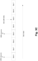
- the UE may apply different precoders for an SRS resource in different timing instance. Then different MCS may be derived from different timing instance. To avoid such the potential MCS mismatch due to precoder change, the timing of SRS and SRI may be identified (e.g., an SRI has to match or be associated with a specific corresponding SRS, and not in random SRS), as discussed with respect to Fig. 3C .
- Fig. 3C illustrates a timing relationship between SRS resources and SRI that is received over higher level signaling (e.g., DCI), according to some embodiments.
- Fig. 3C illustrates UL and DL transmission during various transmission slots 0, ..., 7.
- SRS resource x1 is transmitted from the UE to the gNB; and during slot 3, SRS resource x2 is transmitted from the UE to the gNB.
- the UE receives an UL grant, which includes DCI, where the DCI includes an SRI 505 (the slot numbers are merely examples). Without any pre-defined arrangement, the UE may not know whether the SRI 505 corresponds to the SRS resource x1 or SRS resource x2.
- the SRI in slot k may be used to indicate the latest SRS in corresponding resource before slot (k-k1), where k1 may be pre-defined, may be configured by higher layer signaling or DCI, and/or may be determined by the slot index of next PUSCH transmission.
- the SRI 505 may be associated with SRS resource x1 transmitted in slot 0. If k1 is 0, 1, or 2, the SRI 505 may be associated with SRS resource x2 transmitted in slot 3.
- SRS resources e.g., a sequence of SRS resources
- the UE and the gNB may support bandwidth parts (BWPs).
- a BWP may be UE specific, and may be equal to or smaller than a maximal bandwidth capability supported by a UE.
- a BWP may span at least part of a bandwidth of a wireless communication channel between a UE and a gNB.
- BWP cross carrier or cross bandwidth part
- QCL Quasi-Co-Location
- the SRS resource may be indicated by cross carrier or cross BWP.
- a carrier index and/or BWP index may be configured (e.g., by the gNB).
- the SRS resource in different BWP or carrier may be configured within different SRS resource groups.
- the corresponding SRS resource group index may be indicated by the carrier or BWP index in the DCI.
- Fig. 4 illustrates an eNB and a UE, according to some embodiments.
- Fig. 4 includes block diagrams of an eNB 410 and a UE 430 which are operable to co-exist with each other and other elements of an LTE network. High-level, simplified architectures of eNB 410 and UE 430 are described so as not to obscure the embodiments. It should be noted that in some embodiments, eNB 410 may be a stationary non-mobile device.
- eNB 410 is coupled to one or more antennas 405, and UE 430 is similarly coupled to one or more antennas 425.
- eNB 410 may incorporate or comprise antennas 405, and UE 430 in various embodiments may incorporate or comprise antennas 425.
- eNB 410 and UE 430 are operable to communicate with each other on a network, such as a wireless network.
- eNB 410 and UE 430 may be in communication with each other over a wireless communication channel 450, which has both a downlink path from eNB 410 to UE 430 and an uplink path from UE 430 to eNB 410.
- eNB 410 may include a physical layer circuitry 412, a MAC (media access control) circuitry 414, a processor 416, a memory 418, and a hardware processing circuitry 420.
- MAC media access control
- physical layer circuitry 412 includes a transceiver 413 for providing signals to and from UE 430.
- Transceiver 413 provides signals to and from UEs or other devices using one or more antennas 405.
- MAC circuitry 414 controls access to the wireless medium.
- Memory 418 may be, or may include, a storage media/medium such as a magnetic storage media (e.g., magnetic tapes or magnetic disks), an optical storage media (e.g., optical discs), an electronic storage media (e.g., conventional hard disk drives, solid-state disk drives, or flash-memory-based storage media), or any tangible storage media or non-transitory storage media.
- Hardware processing circuitry 420 may comprise logic devices or circuitry to perform various operations.
- processor 416 and memory 418 are arranged to perform the operations of hardware processing circuitry 420, such as operations described herein with reference to logic devices and circuitry within eNB 410 and/or hardware processing circuitry 420.
- eNB 410 may be a device comprising an application processor, a memory, one or more antenna ports, and an interface for allowing the application processor to communicate with another device.
- UE 430 may include a physical layer circuitry 432, a MAC circuitry 434, a processor 436, a memory 438, a hardware processing circuitry 440, a wireless interface 442, and a display 444.
- a physical layer circuitry 432 may include a physical layer circuitry 432, a MAC circuitry 434, a processor 436, a memory 438, a hardware processing circuitry 440, a wireless interface 442, and a display 444.
- a person skilled in the art would appreciate that other components not shown may be used in addition to the components shown to form a complete UE.
- physical layer circuitry 432 includes a transceiver 433 for providing signals to and from eNB 410 (as well as other eNBs). Transceiver 433 provides signals to and from eNBs or other devices using one or more antennas 425.
- MAC circuitry 434 controls access to the wireless medium.
- Memory 438 may be, or may include, a storage media/medium such as a magnetic storage media (e.g., magnetic tapes or magnetic disks), an optical storage media (e.g., optical discs), an electronic storage media (e.g., conventional hard disk drives, solid-state disk drives, or flash-memory-based storage media), or any tangible storage media or non-transitory storage media.
- Wireless interface 442 may be arranged to allow the processor to communicate with another device.
- Display 444 may provide a visual and/or tactile display for a user to interact with UE 430, such as a touch-screen display.
- Hardware processing circuitry 440 may comprise logic devices or circuitry to perform various operations.
- processor 436 and memory 438 may be arranged to perform the operations of hardware processing circuitry 440, such as operations described herein with reference to logic devices and circuitry within UE 430 and/or hardware processing circuitry 440.
- UE 430 may be a device comprising an application processor, a memory, one or more antennas, a wireless interface for allowing the application processor to communicate with another device, and a touch-screen display.
- FIG. 4 Elements of Fig. 4 , and elements of other figures having the same names or reference numbers, can operate or function in the manner described herein with respect to any such figures (although the operation and function of such elements is not limited to such descriptions).
- Figs. 5-6 and 9-10 also depict embodiments of eNBs, hardware processing circuitry of eNBs, UEs, and/or hardware processing circuitry of UEs, and the embodiments described with respect to Fig. 4 and Figs. 5 -6 and 9-10 can operate or function in the manner described herein with respect to any of the figures.
- eNB 410 and UE 430 are each described as having several separate functional elements, one or more of the functional elements may be combined and may be implemented by combinations of software-configured elements and/or other hardware elements.
- the functional elements can refer to one or more processes operating on one or more processing elements. Examples of software and/or hardware configured elements include Digital Signal Processors (DSPs), one or more microprocessors, DSPs, Field-Programmable Gate Arrays (FPGAs), Application Specific Integrated Circuits (ASICs), Radio-Frequency Integrated Circuits (RFICs), and so on.
- DSPs Digital Signal Processors
- FPGAs Field-Programmable Gate Arrays
- ASICs Application Specific Integrated Circuits
- RFICs Radio-Frequency Integrated Circuits
- one or more devices or circuitries within these hardware processing circuitries may be implemented by combinations of software-configured elements and/or other hardware elements.
- processor 416 and/or one or more other processors which eNB 410 may comprise
- memory 418 and/or other elements or components of eNB 410 (which may include hardware processing circuitry 420) may be arranged to perform the operations of these hardware processing circuitries, such as operations described herein with reference to devices and circuitry within these hardware processing circuitries.
- processor 416 (and/or one or more other processors which eNB 410 may comprise) may be a baseband processor.
- an apparatus of eNB 410 may comprise hardware processing circuitry 500.
- hardware processing circuitry 500 may comprise one or more antenna ports 505 operable to provide various transmissions over a wireless communication channel (such as wireless communication channel 450).
- Antenna ports 505 may be coupled to one or more antennas 507 (which may be antennas 405).
- hardware processing circuitry 500 may incorporate antennas 507, while in other embodiments, hardware processing circuitry 500 may merely be coupled to antennas 507.
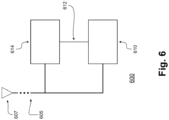
- Fig. 6 illustrates hardware processing circuitries for a UE for generating SRS transmission, based on processing an indicator that indicates an SRS resource type, according to some embodiments.
- a UE may include various hardware processing circuitries discussed herein (such as hardware processing circuitry 600 of Fig. 6 ), which may in turn comprise logic devices and/or circuitry operable to perform various operations.
- UE 430 (or various elements or components therein, such as hardware processing circuitry 440, or combinations of elements or components therein) may include part of, or all of, these hardware processing circuitries.
- an apparatus of UE 430 may comprise hardware processing circuitry 600.
- hardware processing circuitry 600 may comprise one or more antenna ports 605 operable to provide various transmissions over a wireless communication channel (such as wireless communication channel 450).
- Antenna ports 605 may be coupled to one or more antennas 607 (which may be antennas 425).
- hardware processing circuitry 600 may incorporate antennas 607, while in other embodiments, hardware processing circuitry 600 may merely be coupled to antennas 607.
- Hardware processing circuitry 600 may comprise various circuitries operable in accordance with the various embodiments discussed herein. With reference to Fig. 6 , hardware processing circuitry 600 may comprise a first circuitry 610 and/or a second circuitry 620.
- First circuitry 610 may be operable to process a message that includes an indicator of SRS resource set type, e.g., as discussed with respect to Tables 1, 3, 4, and/or 6).
- Second circuitry 620 may be operable to generate an SRS transmission, based on the indicator of the SRS resource set type.
- the message is a first message
- the first circuitry 610 may be operable to process a second message that includes the indicator of SRS resource set type, wherein the indicator of the second message is to indicate that no SRS resource set transmission is to be triggered.
- the first circuitry 610 may be operable to refrain from generating any SRS transmission, in response to processing the second message.
- first circuitry 610 and/or second circuitry 620 may be implemented as separate circuitries. In other embodiments, first circuitry 610 and/or second circuitry 620 may be combined and implemented together in a circuitry without altering the essence of the embodiments.
- Fig. 7 illustrates a method 700 for an eNB for establishing an indicator to indicate a type of SRS resource set to be transmitted by the UE (e.g., as discussed with respect to Tables 1, 3, 4, and/or 6), and transmitting the indicator to the UE, according to some embodiments.
- various methods that may relate to eNB 410 and hardware processing circuitry 420 are discussed herein.
- the actions in method 700 of Fig. 7 are shown in a particular order, the order of the actions can be modified. Thus, the illustrated embodiments can be performed in a different order, and some actions may be performed in parallel.
- Some of the actions and/or operations listed in Fig. 7 are optional in accordance with certain embodiments. The numbering of the actions presented is for the sake of clarity and is not intended to prescribe an order of operations in which the various actions must occur. Additionally, operations from the various flows may be utilized in a variety of combinations.
- the method 700 may be in accordance with the various embodiments discussed herein.
- the method 700 comprises, at 710, establishing an indicator to indicate a selection of a Sounding Reference Signal (SRS) resource set to be transmitted by the UE to the gNB (e.g., as discussed with respect to Tables 1, 3, 4, and/or 6).
- a message e.g., higher level signaling, DCI, etc.
- an interface may send the message to a transmission circuitry, for transmission to a UE.
- the indicator has one of: a first value indicating a selection of a first SRS resource set, a second value indicating a selection of a second SRS resource set, or a third value indicating a selection of a third SRS resource set.
- at least one of the first, second, or third SRS resource sets is associated with one of: SRS for non-codebook based transmission, SRS for codebook based transmission, or SRS for Beam Management.
- the indicator is a first indicator; the one or more circuitries are to generate a sequence of indicators including the first indicator, a second indicator, and a third indicator; the first indicator is to indicate a selection of a first SRS resource set for Beam Management; the second indicator is to indicate a selection of a second SRS resource set for codebook based transmission; and the third indicator is to indicate a selection of a third SRS resource set for non-codebook based transmission.
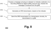
- Fig. 8 illustrates a method 800 for a UE for generating SRS transmission, based on processing an indicator that indicates an SRS resource type, according to some embodiments.
- the method 800 that may relate to UE 430 and hardware processing circuitry 440 are discussed herein.
- the actions in method 800 of Fig. 8 are shown in a particular order, the order of the actions can be modified. Thus, the illustrated embodiments can be performed in a different order, and some actions may be performed in parallel. Some of the actions and/or operations listed in Fig. 8 are optional in accordance with certain embodiments.
- the numbering of the actions presented is for the sake of clarity and is not intended to prescribe an order of operations in which the various actions must occur. Additionally, operations from the various flows may be utilized in a variety of combinations.
- machine readable storage media may have executable instructions that, when executed, cause UE 430 and/or hardware processing circuitry 440 to perform an operation comprising the methods of Fig. 8 .
- Such machine readable storage media may include any of a variety of storage media, like magnetic storage media (e.g., magnetic tapes or magnetic disks), optical storage media (e.g., optical discs), electronic storage media (e.g., conventional hard disk drives, solid-state disk drives, or flash-memory-based storage media), or any other tangible storage media or non-transitory storage media.
- an apparatus may comprise means for performing various actions and/or operations of the methods of Fig. 8 .
- the method 800 may be in accordance with the various embodiments discussed herein.
- the method 800 may comprise, at 810, a processing of a message carrying an indicator to indicate a selection of a Sounding Reference Signal (SRS) resource set (e.g., as discussed with respect to Table 4), where the message is received from the gNB.
- SRS Sounding Reference Signal
- an SRS transmission may be generated, based on the indicator of the SRS resource set.
- the SRS transmission may be sent to a transmission circuitry, e.g., for transmission to a gNB.
- the indicator is a 2-bit indicator. In some embodiments, the indicator has one of: a first value indicating a selection of a first SRS resource set, a second value indicating a selection of a second SRS resource set, or a third value indicating a selection of a third SRS resource set. In some embodiments, one or more of the first, second, or third SRS resource sets are configured with higher layer parameters. In some embodiments, the first SRS resource set is associated with one of: SRS for non-codebook based transmission, SRS for codebook based transmission, or SRS for Beam Management.
- the message is a first message
- the method comprises processing a second message carrying an indicator to indicate that no SRS resource set transmission is to be triggered, wherein the second message is received from the gNB.
- the method comprises refraining from generating a SRS transmission, in response to the second message.
- the SRS transmission is a first SRS transmission; and the method comprises generating a sequence of SRS transmissions including the first SRS transmission; sending the sequence of SRS transmissions to the transmission circuitry; and processing an Uplink (UL) grant that includes an SRS Resource Indicator (SRI), wherein the SRI is associated with a most recent SRS transmission of the sequence of SRS transmissions prior to receiving the SRI.
- SRI SRS Resource Indicator
- the SRS transmission is a first SRS transmission; and the method comprises generating a sequence of SRS transmissions including the first SRS transmission; sending the sequence of SRS transmissions to the transmission circuitry; and processing an Uplink (UL) grant that includes an SRS Resource indicator (SRI), wherein the SRI is received at the UE at a slot n, and wherein the SRI at the slot n is associated with a most recent SRS transmission of the sequence of SRS transmissions that is transmitted prior to the slot n.
- SRI SRS Resource indicator
- the message includes an indicator of a Bandwidth Part (BWP) spanning at least part of a bandwidth of a wireless communication channel between the UE and the gNB, wherein the indicator indicating the selection of the SRS resource set is for the BWP.
- BWP Bandwidth Part
- Fig. 9 illustrates example components of a device, in accordance with some embodiments of the disclosure.
- the device 900 may include application circuitry 902, baseband circuitry 904, Radio Frequency (RF) circuitry 906, front-end module (FEM) circuitry 908, one or more antennas 910, and power management circuitry (PMC) 912 coupled together at least as shown.
- the components of the illustrated device 900 may be included in a UE or a RAN node.
- the device 900 may include less elements (e.g., a RAN node may not utilize application circuitry 902, and instead include a processor/controller to process IP data received from an EPC).
- the device 900 may include additional elements such as, for example, memory/storage, display, camera, sensor, or input/output (I/O) interface.
- additional elements such as, for example, memory/storage, display, camera, sensor, or input/output (I/O) interface.
- the components described below may be included in more than one device (e.g., said circuitries may be separately included in more than one device for Cloud-RAN (C-RAN) implementations).
- C-RAN Cloud-RAN
- the application circuitry 902 may include one or more application processors.
- the application circuitry 902 may include circuitry such as, but not limited to, one or more single-core or multi-core processors.
- the processor(s) may include any combination of general-purpose processors and dedicated processors (e.g., graphics processors, application processors, and so on).
- the processors may be coupled with or may include memory/storage and may be configured to execute instructions stored in the memory/storage to enable various applications or operating systems to run on the device 900.
- processors of application circuitry 902 may process IP data packets received from an EPC.
- the baseband circuitry 904 may include circuitry such as, but not limited to, one or more single-core or multi-core processors.
- the baseband circuitry 904 may include one or more baseband processors or control logic to process baseband signals received from a receive signal path of the RF circuitry 906 and to generate baseband signals for a transmit signal path of the RF circuitry 906.
- Baseband processing circuity 904 may interface with the application circuitry 902 for generation and processing of the baseband signals and for controlling operations of the RF circuitry 906.
- baseband processors 904A-D may be included in modules stored in the memory 904G and executed via a Central Processing Unit (CPU) 904E.
- the radio control functions may include, but are not limited to, signal modulation/demodulation, encoding/decoding, radio frequency shifting, and so on.
- modulation/demodulation circuitry of the baseband circuitry 904 may include Fast-Fourier Transform (FFT), precoding, or constellation mapping/demapping functionality.
- encoding/decoding circuitry of the baseband circuitry 904 may include convolution, tail-biting convolution, turbo, Viterbi, or Low Density Parity Check (LDPC) encoder/decoder functionality.
- LDPC Low Density Parity Check
- the baseband circuitry 904 may provide for communication compatible with one or more radio technologies.
- the baseband circuitry 904 may support communication with an evolved universal terrestrial radio access network (EUTRAN) or other wireless metropolitan area networks (WMAN), a wireless local area network (WLAN), a wireless personal area network (WPAN).
- EUTRAN evolved universal terrestrial radio access network
- WMAN wireless metropolitan area networks
- WLAN wireless local area network
- WPAN wireless personal area network
- multi-mode baseband circuitry Embodiments in which the baseband circuitry 904 is configured to support radio communications of more than one wireless protocol.
- RF circuitry 906 may enable communication with wireless networks using modulated electromagnetic radiation through a non-solid medium.
- the RF circuitry 906 may include switches, filters, amplifiers, and so on to facilitate the communication with the wireless network.
- RF circuitry 906 may include a receive signal path which may include circuitry to down-convert RF signals received from the FEM circuitry 908 and provide baseband signals to the baseband circuitry 904.
- RF circuitry 906 may also include a transmit signal path which may include circuitry to up-convert baseband signals provided by the baseband circuitry 904 and provide RF output signals to the FEM circuitry 908 for transmission.
- the output baseband signals and the input baseband signals may be analog baseband signals, although the scope of the embodiments is not limited in this respect.
- the output baseband signals and the input baseband signals may be digital baseband signals.
- the RF circuitry 906 may include analog-to-digital converter (ADC) and digital-to-analog converter (DAC) circuitry and the baseband circuitry 904 may include a digital baseband interface to communicate with the RF circuitry 906.
- ADC analog-to-digital converter
- DAC digital-to-analog converter
- a separate radio IC circuitry may be provided for processing signals for each spectrum, although the scope of the embodiments is not limited in this respect.
- the synthesizer circuitry 906D may be a fractional-N synthesizer or a fractional N/N+1 synthesizer, although the scope of the embodiments is not limited in this respect as other types of frequency synthesizers may be suitable.
- synthesizer circuitry 906D may be a delta-sigma synthesizer, a frequency multiplier, or a synthesizer comprising a phase-locked loop with a frequency divider.
- the synthesizer circuitry 906D may be configured to synthesize an output frequency for use by the mixer circuitry 906A of the RF circuitry 906 based on a frequency input and a divider control input. In some embodiments, the synthesizer circuitry 906D may be a fractional N/N+1 synthesizer.
- frequency input may be provided by a voltage controlled oscillator (VCO), although that is not a requirement.
- VCO voltage controlled oscillator
- Divider control input may be provided by either the baseband circuitry 904 or the applications processor 902 depending on the desired output frequency.
- a divider control input (e.g., N) may be determined from a look-up table based on a channel indicated by the applications processor 902.
- Synthesizer circuitry 906D of the RF circuitry 906 may include a divider, a delay-locked loop (DLL), a multiplexer and a phase accumulator.
- the divider may be a dual modulus divider (DMD) and the phase accumulator may be a digital phase accumulator (DPA).
- the DMD may be configured to divide the input signal by either N or N+1 (e.g., based on a carry out) to provide a fractional division ratio.
- the DLL may include a set of cascaded, tunable, delay elements, a phase detector, a charge pump and a D-type flip-flop.
- the delay elements may be configured to break a VCO period up into Nd equal packets of phase, where Nd is the number of delay elements in the delay line.
- Nd is the number of delay elements in the delay line.
- synthesizer circuitry 906D may be configured to generate a carrier frequency as the output frequency, while in other embodiments, the output frequency may be a multiple of the carrier frequency (e.g., twice the carrier frequency, four times the carrier frequency) and used in conjunction with quadrature generator and divider circuitry to generate multiple signals at the carrier frequency with multiple different phases with respect to each other.
- the output frequency may be a LO frequency (fLO).
- the RF circuitry 906 may include an IQ/polar converter.
- FEM circuitry 908 may include a receive signal path which may include circuitry configured to operate on RF signals received from one or more antennas 910, amplify the received signals and provide the amplified versions of the received signals to the RF circuitry 906 for further processing.
- FEM circuitry 908 may also include a transmit signal path which may include circuitry configured to amplify signals for transmission provided by the RF circuitry 906 for transmission by one or more of the one or more antennas 910.
- the amplification through the transmit or receive signal paths may be done solely in the RF circuitry 906, solely in the FEM 908, or in both the RF circuitry 906 and the FEM 908.
- the FEM circuitry 908 may include a TX/RX switch to switch between transmit mode and receive mode operation.
- the FEM circuitry may include a receive signal path and a transmit signal path.
- the receive signal path of the FEM circuitry may include an LNA to amplify received RF signals and provide the amplified received RF signals as an output (e.g., to the RF circuitry 906).
- the transmit signal path of the FEM circuitry 908 may include a power amplifier (PA) to amplify input RF signals (e.g., provided by RF circuitry 906), and one or more filters to generate RF signals for subsequent transmission (e.g., by one or more of the one or more antennas 910).
- PA power amplifier
- Fig. 9 shows the PMC 912 coupled only with the baseband circuitry 904.
- the PMC 912 may be additionally or alternatively coupled with, and perform similar power management operations for, other components such as, but not limited to, application circuitry 902, RF circuitry 906, or FEM 908.
- the PMC 912 may control, or otherwise be part of, various power saving mechanisms of the device 900. For example, if the device 900 is in an RRC_Connected state, where it is still connected to the RAN node as it expects to receive traffic shortly, then it may enter a state known as Discontinuous Reception Mode (DRX) after a period of inactivity. During this state, the device 900 may power down for brief intervals of time and thus save power.
- DRX Discontinuous Reception Mode
- the device 900 may transition off to an RRC_Idle state, where it disconnects from the network and does not perform operations such as channel quality feedback, handover, and so on.
- the device 900 goes into a very low power state and it performs paging where again it periodically wakes up to listen to the network and then powers down again.
- the device 900 may not receive data in this state, in order to receive data, it must transition back to RRC_Connected state.
- An additional power saving mode may allow a device to be unavailable to the network for periods longer than a paging interval (ranging from seconds to a few hours). During this time, the device is totally unreachable to the network and may power down completely. Any data sent during this time incurs a large delay and it is assumed the delay is acceptable.
- Processors of the application circuitry 902 and processors of the baseband circuitry 904 may be used to execute elements of one or more instances of a protocol stack.
- processors of the baseband circuitry 904 alone or in combination, may be used execute Layer 3, Layer 2, or Layer 1 functionality, while processors of the application circuitry 904 may utilize data (e.g., packet data) received from these layers and further execute Layer 4 functionality (e.g., transmission communication protocol (TCP) and user datagram protocol (UDP) layers).
- Layer 3 may comprise a radio resource control (RRC) layer, described in further detail below.
- RRC radio resource control
- first embodiment may be combined with a second embodiment anywhere the particular features, structures, functions, or characteristics associated with the two embodiments are not mutually exclusive.
- DRAM Dynamic RAM
- Example 1 An apparatus of a User Equipment (UE) operable to communicate with a fifth-generation Evolved Node B (gNB) on a wireless network, comprising: one or more circuitries to: process a message carrying an indicator to indicate a selection of a Sounding Reference Signal (SRS) resource set, wherein the message is received from the gNB, and generate an SRS transmission based on the indicator; and an interface to send the SRS transmission to a transmission circuitry.
- UE User Equipment
- gNB Evolved Node B
- SRS Sounding Reference Signal
- Example 2 The apparatus of example 1 or any other examples herein, wherein: the indicator is a 2-bit indicator.
- Example 3 The apparatus of example 1 or any other examples herein, wherein: the indicator has one of: a first value indicating a selection of a first SRS resource set, a second value indicating a selection of a second SRS resource set, or a third value indicating a selection of a third SRS resource set.
- Example 4 The apparatus of example 3 or any other examples herein, wherein: one or more of the first, second, or third SRS resource sets are configured with higher layer parameters.
- Example 7 The apparatus of example 6 or any other examples herein, wherein the one or more circuitries are to: refrain from generating a SRS transmission, in response to the second message.
- Example 10 The apparatus of any of examples 1-5 or any other examples herein, wherein: the message includes an indicator of a Bandwidth Part (BWP) spanning at least part of a bandwidth of a wireless communication channel between the UE and the gNB, wherein the indicator indicating the selection of the SRS resource set is for the BWP.
- BWP Bandwidth Part
- Example 11 A User Equipment (UE) device comprising an application processor, a memory, one or more antennas, a wireless interface for allowing the application processor to communicate with another device, and a touch-screen display, the UE device including the apparatus of any of examples 1-6 or any other examples herein.
- UE User Equipment
- Example 14 The machine readable storage media of example 12 or any other examples herein, wherein: the indicator has one of: a first value indicating a selection of a first SRS resource set, a second value indicating a selection of a second SRS resource set, or a third value indicating a selection of a third SRS resource set.
- Example 21 The machine readable storage media of any of examples 12-16 or any other examples herein, wherein: the message includes an indicator of a Bandwidth Part (BWP) spanning at least part of a bandwidth of a wireless communication channel between the UE and the gNB, wherein the indicator indicating the selection of the SRS resource set is for the BWP.
- BWP Bandwidth Part
Landscapes
- Engineering & Computer Science (AREA)
- Signal Processing (AREA)
- Computer Networks & Wireless Communication (AREA)
- Mobile Radio Communication Systems (AREA)
Applications Claiming Priority (5)
| Application Number | Priority Date | Filing Date | Title |
|---|---|---|---|
| CN2017097167 | 2017-08-11 | ||
| CN2017010523 | 2017-10-03 | ||
| US201862620178P | 2018-01-22 | 2018-01-22 | |
| PCT/US2018/046053 WO2019032855A1 (en) | 2017-08-11 | 2018-08-09 | CONTROL SIGNALING FOR SURFACE REFERENCE SIGNAL (SRS) |
| EP18762957.1A EP3665848A1 (de) | 2017-08-11 | 2018-08-09 | Kontrollsignalisierung für lotungsreferenzsignal (srb ) |
Related Parent Applications (1)
| Application Number | Title | Priority Date | Filing Date |
|---|---|---|---|
| EP18762957.1A Division EP3665848A1 (de) | 2017-08-11 | 2018-08-09 | Kontrollsignalisierung für lotungsreferenzsignal (srb ) |
Publications (2)
| Publication Number | Publication Date |
|---|---|
| EP4290796A2 true EP4290796A2 (de) | 2023-12-13 |
| EP4290796A3 EP4290796A3 (de) | 2024-01-24 |
Family
ID=70611701
Family Applications (2)
| Application Number | Title | Priority Date | Filing Date |
|---|---|---|---|
| EP18762957.1A Pending EP3665848A1 (de) | 2017-08-11 | 2018-08-09 | Kontrollsignalisierung für lotungsreferenzsignal (srb ) |
| EP23199448.4A Pending EP4290796A3 (de) | 2017-08-11 | 2018-08-09 | Kontrollsignalisierung für lotungsreferenzsignal (srb ) |
Family Applications Before (1)
| Application Number | Title | Priority Date | Filing Date |
|---|---|---|---|
| EP18762957.1A Pending EP3665848A1 (de) | 2017-08-11 | 2018-08-09 | Kontrollsignalisierung für lotungsreferenzsignal (srb ) |
Country Status (1)
| Country | Link |
|---|---|
| EP (2) | EP3665848A1 (de) |
Cited By (1)
| Publication number | Priority date | Publication date | Assignee | Title |
|---|---|---|---|---|
| US20240155634A1 (en) * | 2021-04-30 | 2024-05-09 | Qualcomm Incorporated | Frequency selective precoder indication in wireless communications |
-
2018
- 2018-08-09 EP EP18762957.1A patent/EP3665848A1/de active Pending
- 2018-08-09 EP EP23199448.4A patent/EP4290796A3/de active Pending
Cited By (1)
| Publication number | Priority date | Publication date | Assignee | Title |
|---|---|---|---|---|
| US20240155634A1 (en) * | 2021-04-30 | 2024-05-09 | Qualcomm Incorporated | Frequency selective precoder indication in wireless communications |
Also Published As
| Publication number | Publication date |
|---|---|
| EP3665848A1 (de) | 2020-06-17 |
| EP4290796A3 (de) | 2024-01-24 |
Similar Documents
| Publication | Publication Date | Title |
|---|---|---|
| US11804990B2 (en) | Control signaling for sounding reference signal (SRS) | |
| US12156169B2 (en) | System and method for multiplexing of tracking reference signal and synchronization signal block | |
| US11757512B2 (en) | Channel state information report for phase tracking reference signal port selection | |
| EP3536101B1 (de) | Strahlreziprozitätsanzeige und gemeinsames uplink-downlink-strahlmanagement | |
| US12207148B2 (en) | Beamforming for dynamic cell switching | |
| US20210144038A1 (en) | Control signaling for demodulation reference signal antenna port indication | |
| US11903093B2 (en) | Physical downlink shared channel transmission for multi-point | |
| EP3596871B1 (de) | Phasenverfolgungsreferenzsignalanzeige bei mehrbenutzerüberpositionsübertragung | |
| WO2018031825A1 (en) | System and method for enhanced csi feedback | |
| WO2018064608A1 (en) | Demodulation reference signal design and multiplexing using different numerologies | |
| US11224023B2 (en) | Timing advance for grantless uplink transmission | |
| EP4290796A2 (de) | Kontrollsignalisierung für lotungsreferenzsignal (srb ) | |
| WO2018094175A1 (en) | Orthogonal resource slicing for autonomous transmission |
Legal Events
| Date | Code | Title | Description |
|---|---|---|---|
| PUAI | Public reference made under article 153(3) epc to a published international application that has entered the european phase |
Free format text: ORIGINAL CODE: 0009012 |
|
| STAA | Information on the status of an ep patent application or granted ep patent |
Free format text: STATUS: REQUEST FOR EXAMINATION WAS MADE |
|
| 17P | Request for examination filed |
Effective date: 20230925 |
|
| AC | Divisional application: reference to earlier application |
Ref document number: 3665848 Country of ref document: EP Kind code of ref document: P |
|
| AK | Designated contracting states |
Kind code of ref document: A2 Designated state(s): AL AT BE BG CH CY CZ DE DK EE ES FI FR GB GR HR HU IE IS IT LI LT LU LV MC MK MT NL NO PL PT RO RS SE SI SK SM TR |
|
| PUAL | Search report despatched |
Free format text: ORIGINAL CODE: 0009013 |
|
| AK | Designated contracting states |
Kind code of ref document: A3 Designated state(s): AL AT BE BG CH CY CZ DE DK EE ES FI FR GB GR HR HU IE IS IT LI LT LU LV MC MK MT NL NO PL PT RO RS SE SI SK SM TR |
|
| RIC1 | Information provided on ipc code assigned before grant |
Ipc: H04L 25/02 20060101ALI20231215BHEP Ipc: H04W 72/04 20230101ALI20231215BHEP Ipc: H04B 7/0408 20170101ALI20231215BHEP Ipc: H04L 5/00 20060101AFI20231215BHEP |
|
| GRAP | Despatch of communication of intention to grant a patent |
Free format text: ORIGINAL CODE: EPIDOSNIGR1 |
|
| STAA | Information on the status of an ep patent application or granted ep patent |
Free format text: STATUS: GRANT OF PATENT IS INTENDED |
|
| INTG | Intention to grant announced |
Effective date: 20260220 |