EP4290766A1 - A modulator and a method for modulating the phase of a radiofrequency signal - Google Patents
A modulator and a method for modulating the phase of a radiofrequency signal Download PDFInfo
- Publication number
- EP4290766A1 EP4290766A1 EP22305818.1A EP22305818A EP4290766A1 EP 4290766 A1 EP4290766 A1 EP 4290766A1 EP 22305818 A EP22305818 A EP 22305818A EP 4290766 A1 EP4290766 A1 EP 4290766A1
- Authority
- EP
- European Patent Office
- Prior art keywords
- signal
- phase
- modulator
- individual
- signals
- Prior art date
- Legal status (The legal status is an assumption and is not a legal conclusion. Google has not performed a legal analysis and makes no representation as to the accuracy of the status listed.)
- Pending
Links
Images

Classifications
-
- H—ELECTRICITY
- H03—ELECTRONIC CIRCUITRY
- H03C—MODULATION
- H03C5/00—Amplitude modulation and angle modulation produced simultaneously or at will by the same modulating signal
-
- H—ELECTRICITY
- H03—ELECTRONIC CIRCUITRY
- H03C—MODULATION
- H03C1/00—Amplitude modulation
- H03C1/08—Amplitude modulation by means of variable impedance element
-
- H—ELECTRICITY
- H03—ELECTRONIC CIRCUITRY
- H03C—MODULATION
- H03C3/00—Angle modulation
- H03C3/38—Angle modulation by converting amplitude modulation to angle modulation
- H03C3/40—Angle modulation by converting amplitude modulation to angle modulation using two signal paths the outputs of which have a predetermined phase difference and at least one output being amplitude-modulated
Definitions
- the present invention relates to a phase modulator for modulating the phase of a radiofrequency signal, and in particular of a microwave signal.
- the invention also relates to a method for modulating the phase of a radiofrequency signal, with such a modulator, and the use of a such a modulator for simulating the direction of arrival of a received signal, or the direction of emission of an emitted signal.
- the field of the invention is the field of phase modulator for radiofrequency signals.
- the direction of arrival, or the direction of emission, of a radiofrequency, RF, signal may be simulated by phase modulation of said signal.
- phase modulation of a RF signal consists in using a system combining a phase shifter and a variable attenuator.
- a system has the advantage of being cheaper compared to a vector modulator, in particular for wide bandwidth applications.
- the phase and the gain are tied so that the change of the phase modifies the gain, vice versa. This amounts to a time consuming and complicated calibration of the system.
- a purpose of the present invention is to overcome at least one of these drawbacks.
- Another purpose of the invention is to provide a solution for phase modulating a RF signal that is cheaper and easier to calibrate compared to the solutions of the prior art, especially for wide bandwidth applications.
- the invention makes it possible to achieve at least one of these aims by a modulator for modulating the phase and the amplitude of a radiofrequency signal, called input signal, said modulator comprising:
- the present invention proposes a modulator that may be developed with conventional components that are more affordable compared to a vector modulator, such as phase shifter(s), attenuator(s), splitter(s) and combiner(s).
- the modulator of the present invention is less expensive compared to vectors modulators, especially for wide bandwidth applications, for example of an octave.
- the modulators of the prior art combining a phase shifter and an attenuator, it is necessary to calibrate the modulator for many points, each corresponding to a combination of a phase shift and amplitude shift for the input signal, which is very time consuming.
- the modulator according to the invention requires a less time consuming calibration.
- the input signal is split into two signals that are processed independently in order to get in phase quadrature first and second signals: there is a phase shift of 90° between the first signal and the second signal.
- the modulator according to the invention allows individual control of the amplitude of the first signal and/or individual control of the amplitude if the second signal.
- phase and the amplitude of the combined signal may be adjusted easily by adjusting the amplitude of the first and the second signals, making the calibration of the modulator easier and faster.
- the global phase shifter may be an adjustable, or controllable, phase shifter.
- phase shift of the output signal it is possible to adjust the phase shift of the output signal to a desired value.
- the desired phase shift is applied to the combined signal, which is much more easy to calibrate compared to phase shifts applied to each way of the systems of the prior art.
- the global phase shifter may be a 0-360° phase shifter.
- the modulator according to the invention makes it possible to modulate the phase of the input signal to a desired value that is between 0° and 360°, i.e. to cover the whole range of phase values for a RF signal.
- the assembly may comprise a first path dedicated to the first signal and a second path dedicated to the second signal.
- first signal and the second signal are processed individually.
- the assembly may comprise:
- At least one, and in particular each of, the individual phase shifter is an adjustable, or controllable, phase shifter.
- it is possible to adjust the phase shift applied to at least one of the first and second signals individually in order to get the first signal and the second signal in phase quadrature.
- At least one of the individual phase shifters may be a 0-360° phase shifter.
- Such individual attenuators make it possible to intervene on the amplitude of each of the first and second signals individually.
- the gain of the signal is modified by said phase shifter because the phase shifter is not a perfect phase shifter.
- the individual attenuator may thus be used to balance the modification of the gain induced by the phase shifter.
- At least one component of the modulator according to the invention i.e. at least one of the splitter, the combiner, the common phase shifter, the individual phase shifter(s) and the attenuator(s), may be a software component.
- At least one component of the modulator according to the invention i.e. at least one of the splitter, the combiner, the common phase shifter, the individual phase shifter(s) and the attenuator(s), may be an individual component.
- the modulator according to the invention may also comprise a controller for adjusting or controlling:
- the controller may be configured to control/adjust:
- the controller may be any electronic or computerized unit such as a processor, a calculator, an electronic chip, a computer, etc.
- the computer program may be in any programming language such as C, C++, JAVA, Python, etc.
- the computer program may be in machine language.
- the computer program may be stored, in a non-transient memory, such as a USB stick, a flash memory, a hard-disc, a processor, a programmable electronic chop, etc.
- a non-transient memory such as a USB stick, a flash memory, a hard-disc, a processor, a programmable electronic chop, etc.
- the computer program may be stored in a computerized device such as a Smartphone, a tablet, a computer, a server, etc.
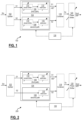
- FIGURE 1 is a diagrammatic representation of a non-limitative example of a modulator according to the present invention.
- the modulator 100 shown in FIGURE 1 , may be used to modulate the phase of a RF signal, and in particular of a microwave signal, Sin, in order to obtain an output signal, Sout, on the FIGURE 1 , the phase of which is shifted.
- the modulator 100 comprises a splitter 102 for splitting the input signal Sin into a first signal S1 and a second signal S2 having the same amplitude.
- the splitter 102 may be a conventional splitter. In theory, an ideal splitter should not introduce a phase shift between the first signal S1 and S2, but in fact the splitter 102 introduces a small phase shift and a small amplitude gap, between the first signal S1 and the second signal S2.
- the first signal S1 and the second signal S2 are then processed in an assembly 104 for introducing a 90° phase difference between said first signal S1 and said second signal S2, and delivering in phase quadrature first and second signals S1, S2.
- the phase shifting assembly 104 may be realized with conventional components and may be any phase shifting assembly.
- the phase shifting assembly 104 comprises a first path 106, dedicated to the first signal S1, for processing the first signal S1 individually and independently of the second signal S2.
- the phase shifting assembly 104 also comprises a second path 108, dedicated to the second signal S2, for processing the second signal S2 individually and independently of the first signal S1.
- the amplitude of the combined signal Sc output by the combiner 118 may also be adjusted by adjusting:
- the modulator 100 also comprises a global phase shifter 120, and in particular a 0-360° adjustable and controllable phase shifter 120, applying a desired phase shift, PP, to the combined signal Sc and provide an output signal Sout corresponding to the input signal Sin with the desired phase shift PP, and optionally a desired amplitude shift.
- a global phase shifter 120 and in particular a 0-360° adjustable and controllable phase shifter 120, applying a desired phase shift, PP, to the combined signal Sc and provide an output signal Sout corresponding to the input signal Sin with the desired phase shift PP, and optionally a desired amplitude shift.
- the modulator 100 there is only needed a unique phase difference of 90° between the two ways, i.e. between the first signal S1 and the second signal S2, to obtain in phase quadrature signals.
- a desired phase shift may be applied to the combined signal by adjusting the amplitude of the first and the second signals.
- the calibration of the modulator 100 is much easier and much less time consuming, compared to the systems of the prior art combining a phase shifter and an attenuator, the systems requiring calibration for different values of phase shift between the two ways.
- the individual phase shifter 110 applies a phase change to the first signal S1, in order to obtain a 90° phase difference with respect to second signal S2.
- the individual phase shifter 110 should not introduce an amplitude change to first signal S1.
- the phase shifter 110 introduces a small amplitude change to the first signal S1.
- the attenuator 112 may be used to make up the amplitude change introduced by the individual phase shifter 110.
- a perfect attenuator should not introduce a phase shift to the first signal. But in real conditions, the individual attenuator 112 introduces a small phase change.
- the individual phase shifter 110 may then be used to make up the small phase change introduced in the first signal by the individual attenuator 112. This process may be repeated several times, for example 2 or 3 times, to calibrate the first path 106 of the assembly 104.
- the calibration process is carried out until the first and the second paths are balanced so that, when the combination of the first and the second signals provides a combined signal with a phase of 45° +/- x°. This reduces the phase shift induced by the individual attenuators, and thus the overall calibration process of the modulator 100.
- a perfect global phase shifter should not modify the amplitude of the combined signal Sc. But, the global phase shifter 120 will introduce a small amplitude change into the combined signal Sc. The small amplitude change may be made up with the individual attenuators 112 and 116 of the assembly 104.
- the modulator 100 of the FIGURE 1 may also comprise a controller for adjusting or controlling:
- controller 130 may be configured to control/adjust:
- the controller 130 may be configured to control the global phase shifter 120, each individual phase shifter 110 and 114, and each individual attenuator 112 and 116.
- the assembly 104 comprises an individual phase sifter and an individual attenuator for each of the first and second signals.
- the assembly may not comprise individual phase shifter and/or an individual attenuator of the first signal, or for the second signal.
- FIGURE 2 is a diagrammatic representation of another non-limitative example of a modulator according to the present invention.
- the modulator 200 shown in FIGURE 2 , may be used to modulate the phase of a RF signal, and in particular of a microwave signal, Sin, in order to obtain an output signal, Sout, the phase of which is shifted.
- the modulator 200 comprises all the components of the modulator of the FIGURE 1 , except the individual phase shifter 114.
- the phase shift of 90° between the first and the second signals S1 and S2 are obtained only through a phase shift applied to the first signal S1 by the individual phase shifter 110.
- FIGURE 3 is a diagrammatic representation of a non-limitative example of a method according to the present invention.
- the method 300 may be used to modulate the phase of a RF signal, and in particular of a microwave signal, with a modulator according to the invention, and in particular with the modulator 100 of FIGURE 1 or the modulator 200 of FIGURE 2 .
- a phase shift is applied to at least one of the signals S1 and S2 in order to obtain a 90° phase difference between said first and second signals and delivering in phase quadrature first and second signals S1 and S2.
- the phase shift may be applied with an assembly comprising respective individual paths dedicated to each of the first signal S1 and second signal S2, as shown in FIGURE 2 .
- the step 304 provides in phase quadrature signals S1 and S2.
- the modulator according to the invention may need to be calibrated.
Landscapes
- Waveguide Switches, Polarizers, And Phase Shifters (AREA)
Abstract
- a splitter (102) for splitting the input signal (Sin) into a first signal (S1) and a second signal (S2);
- an assembly (104) comprising:
▪ at least one individual phase shifter (110;114) for individually shifting the phase of at least one of the first and second signals (S1,S2) in order to obtain in phase quadrature first and second signals, and
▪ at least one individual attenuator (112,116) for individually adjusting the amplitude of at least one of the first and second signals (S1,S2);
- a combiner (118) for combining said in phase quadrature first and second signals (S1,S2) output by said assembly (104), and delivering a combined signal (Sc); and
- a global phase shifter (120) for applying a phase shift to said combined signal (Sc) and delivering an output signal (Sout).
The invention further relates to a method and a computer program for modulating the phase of a radiofrequency signal (Sin).
Description
- The present invention relates to a phase modulator for modulating the phase of a radiofrequency signal, and in particular of a microwave signal. The invention also relates to a method for modulating the phase of a radiofrequency signal, with such a modulator, and the use of a such a modulator for simulating the direction of arrival of a received signal, or the direction of emission of an emitted signal.
- The field of the invention is the field of phase modulator for radiofrequency signals.
- It is well known that the direction of arrival, or the direction of emission, of a radiofrequency, RF, signal may be simulated by phase modulation of said signal.
- Such a phase modulation of a signal may be done with a vector modulator. The signal is input in the vector modulator, which, in turn, outputs an output signal with a phase shift that is chosen in the vector modulator. A vector modulator allows independent adjustment of the phase and of the amplitude, so that the phase and the amplitude may also be controlled independently. But, a standard vector modulator has a low bandwidth. A wide bandwidth requires specific vector modulator, or and assembly of several vector modulators, which is very expensive.
- Another solution for phase modulation of a RF signal consists in using a system combining a phase shifter and a variable attenuator. Such a system has the advantage of being cheaper compared to a vector modulator, in particular for wide bandwidth applications. But, in a such a system the phase and the gain are tied so that the change of the phase modifies the gain, vice versa. This amounts to a time consuming and complicated calibration of the system.
- A purpose of the present invention is to overcome at least one of these drawbacks.
- Another purpose of the invention is to provide a solution for phase modulating a RF signal that is cheaper and easier to calibrate compared to the solutions of the prior art, especially for wide bandwidth applications.
- The invention makes it possible to achieve at least one of these aims by a modulator for modulating the phase and the amplitude of a radiofrequency signal, called input signal, said modulator comprising:
- a splitter for splitting the input signal into a first signal and a second signal;
- an assembly comprising:
- ▪ at least one individual phase shifter for individually shifting the phase of at least one of the first and second signals in order to obtain in phase quadrature first and second signals, and
- ▪ at least one individual attenuator for individually adjusting the amplitude of at least one of the first and second signals;
- a combiner for combining said in phase quadrature first and second signals output by said assembly, and delivering a combined signal; and
- a global phase shifter for applying a phase shift to said combined signal and delivering an output signal.
- The present invention proposes a modulator that may be developed with conventional components that are more affordable compared to a vector modulator, such as phase shifter(s), attenuator(s), splitter(s) and combiner(s). Thus, the modulator of the present invention is less expensive compared to vectors modulators, especially for wide bandwidth applications, for example of an octave.
- Plus, in the modulators of the prior art combining a phase shifter and an attenuator, it is necessary to calibrate the modulator for many points, each corresponding to a combination of a phase shift and amplitude shift for the input signal, which is very time consuming. The modulator according to the invention requires a less time consuming calibration.
- Indeed, in the modulator according to the invention, the input signal is split into two signals that are processed independently in order to get in phase quadrature first and second signals: there is a phase shift of 90° between the first signal and the second signal. Plus, the modulator according to the invention allows individual control of the amplitude of the first signal and/or individual control of the amplitude if the second signal. Thus, the phase and the amplitude of the combined signal, provided by the combiner, are given by the following relations:


- Thus, the phase and the amplitude of the combined signal may be adjusted easily by adjusting the amplitude of the first and the second signals, making the calibration of the modulator easier and faster.
- According to some embodiments, the global phase shifter may be an adjustable, or controllable, phase shifter.
- Thus, it is possible to adjust the phase shift of the output signal to a desired value. The desired phase shift is applied to the combined signal, which is much more easy to calibrate compared to phase shifts applied to each way of the systems of the prior art.
- In some embodiments, the global phase shifter may be a 0-360° phase shifter.
- Thus, the modulator according to the invention makes it possible to modulate the phase of the input signal to a desired value that is between 0° and 360°, i.e. to cover the whole range of phase values for a RF signal.
- In some embodiments, the assembly may comprise a first path dedicated to the first signal and a second path dedicated to the second signal.
- Thus the first signal and the second signal are processed individually.
- Plus, with dedicated paths to the first signal and to the second signal it is possible to process the first and the signals in parallel.
- In some embodiments, the assembly may comprise:
- an individual phase shifter for the first signal, and
- an individual phase shifter for the second signal.
- Thus, it possible to intervene on the phase shift applied to each of the the first and second signals individually without interfering on the other signal.
- In some embodiments, at least one, and in particular each of, the individual phase shifter is an adjustable, or controllable, phase shifter. Thus, it is possible to adjust the phase shift applied to at least one of the first and second signals individually in order to get the first signal and the second signal in phase quadrature.
- In some embodiments, at least one of the individual phase shifters may be a 0-360° phase shifter.
- Thus it is possible to apply a desired phase shift to at least one, and in particular each, of the first and the second signals in order the get these signals in phase quadrature. In other words, it is possible to apply a desired phase shift to the first and/or the second signal, as long as the phase difference between the two signal is equal to 90°.
- In some embodiments, the assembly may comprise:
- an individual attenuator for the first signal, and
- an individual attenuator for the second signal;
- Such individual attenuators make it possible to intervene on the amplitude of each of the first and second signals individually.
- On the one hand, when applying a phase shift on a signal, i.e. the first or the second signal, with the individual phase shifter, the gain of the signal is modified by said phase shifter because the phase shifter is not a perfect phase shifter. The individual attenuator may thus be used to balance the modification of the gain induced by the phase shifter.
- On the other hand, and above all the phase of the combined signal issued by the combiner is directly related to the amplitude of the first and to the amplitude of the second signal, as indicated above (see Relation 1). Thus, the individual attenuators used to individually adjust the amplitude of the first signal and the amplitude of the second signal make it possible to adjust the phase of the combined signal issued by the combiner, and thus the phase of the output signal output by the modulator according to the invention.
- In some embodiments, at least one, and in particular each of, the individual attenuators is an adjustable, or controllable, attenuator. Thus, it is possible order to get the first signal and the second signal in phase quadrature.
- At least one component of the modulator according to the invention, i.e. at least one of the splitter, the combiner, the common phase shifter, the individual phase shifter(s) and the attenuator(s), may be a hardware component.
- At least one component of the modulator according to the invention, i.e. at least one of the splitter, the combiner, the common phase shifter, the individual phase shifter(s) and the attenuator(s), may be a software component.
- At least one component of the modulator according to the invention, i.e. at least one of the splitter, the combiner, the common phase shifter, the individual phase shifter(s) and the attenuator(s), may be an individual component.
- At least two components of the modulator according to the invention, i.e. at least two of the splitter, the combiner, the common phase shifter, the individual phase shifter(s) and the attenuator(s), may be integrated or combined in a single component.
- The modulator according to the invention may also comprise a controller for adjusting or controlling:
- the phase shift applied to the input signal, and
- optionally, the amplitude of the output signal Sout.
- To do this, the controller may be configured to control/adjust:
- the phase shift applied by the global phase shifter, and
- the relative amplitude of the first and the second signal. For example, the controller may adjust/control the gain of at least one, and in particular each, of the individual attenuators.
- In some embodiments, the controller may be configured to control the global phase shifter, each individual phase shifter and each individual attenuator.
- The controller may be any electronic or computerized unit such as a processor, a calculator, an electronic chip, a computer, etc.
- According to another aspect of the same invention, it is proposed a use of a modulator for simulating:
- a direction of arrival of a received RF signal, or
- a direction of emission of an emitted RF signal;
- According to another aspect of the same invention, it is proposed a method for modulating the phase and the amplitude of a radiofrequency, RF, signal, called input signal, with a modulator according to the invention, said method comprising the following steps:
- splitting the input signal into a first signal and a second signal;
- phase shifting for applying a 90° phase difference between said first and second signals, and delivering in phase quadrature first and second signals;
- adjusting relative amplitudes of said first and second signals,
- combining said in phase quadrature first and second signals and delivering a combined signal; and
- applying a phase shift to said combined signal and delivering an output signal.
- The method according to the invention may further comprise at least one of the optional features, or any combination of said optional features, indicated above with respect to the modulator according to the invention, that are not repeated here for sake of brevity.
- Moreover, in some embodiments, the method according of the invention may further comprise a calibration phase of the modulator for at least one desired phase shift value.
- The calibration phase may comprise the following steps:
- the individual phase shifter(s) and the individual attenuator(s) of the assembly are adjusted to obtain in phase quadrature first and second signals;
- the individual attenuator(s) of the assembly is(are) adjusted independently, and the amplitude and the added phase shifting from 90° is recorded for each path;
- the individual phase shifter(s) are adjusted independently over a short range and the added amplitude is recorded;
- the range of the individual attenuator(s) and individual phase shifter(s) which could be used are determined by the added phase shifting and added amplitude depending on the required precision. The phase and the amplitude are controlled according to the following relations:


- the global phase shifter is adjusted, in particular over 360°, and the induced amplitude change is compensated by the individual phase shifter(s) and the individual attenuator(s).
- According to another aspect of the same invention, it is proposed a computer program comprising instructions, which when executed by a computer, cause the computer to carry out:
- the steps of the method according to the invention, or
- the functions carried out by the modulator according to the invention.
- The computer program may be in any programming language such as C, C++, JAVA, Python, etc.
- The computer program may be in machine language.
- The computer program may be stored, in a non-transient memory, such as a USB stick, a flash memory, a hard-disc, a processor, a programmable electronic chop, etc.
- The computer program may be stored in a computerized device such as a Smartphone, a tablet, a computer, a server, etc.
- Other advantages and characteristics will become apparent on examination of the detailed description of an embodiment which is in no way limitative, and the attached figures, where:
-
Figure 1 is a diagrammatic representation of a non-limitative example of a modulator according to the invention; -
Figure 2 is a diagrammatic representation of another non-limitative example of a modulator according to the invention; and -
Figure 3 is a diagrammatic representation of a non-limitative example of a method according to the present invention. - It is well understood that the embodiments that will be described below are in no way limitative. In particular, it is possible to imagine variants of the invention comprising only a selection of the characteristics described hereinafter, in isolation from the other characteristics described, if this selection of characteristics is sufficient to confer a technical advantage or to differentiate the invention with respect to the state of the prior art. Such a selection comprises at least one, preferably functional, characteristic without structural details, or with only a part of the structural details if this part alone is sufficient to confer a technical advantage or to differentiate the invention with respect to the prior art.
- In the FIGURES, elements common to several figures retain the same reference.
-
FIGURE 1 is a diagrammatic representation of a non-limitative example of a modulator according to the present invention. - The
modulator 100, shown inFIGURE 1 , may be used to modulate the phase of a RF signal, and in particular of a microwave signal, Sin, in order to obtain an output signal, Sout, on theFIGURE 1 , the phase of which is shifted. - The
modulator 100 comprises asplitter 102 for splitting the input signal Sin into a first signal S1 and a second signal S2 having the same amplitude. Thesplitter 102 may be a conventional splitter. In theory, an ideal splitter should not introduce a phase shift between the first signal S1 and S2, but in fact thesplitter 102 introduces a small phase shift and a small amplitude gap, between the first signal S1 and the second signal S2. - The first signal S1 and the second signal S2 are then processed in an
assembly 104 for introducing a 90° phase difference between said first signal S1 and said second signal S2, and delivering in phase quadrature first and second signals S1, S2. Thephase shifting assembly 104 may be realized with conventional components and may be any phase shifting assembly. - In the example shown in
FIGURE 1 , thephase shifting assembly 104 comprises afirst path 106, dedicated to the first signal S1, for processing the first signal S1 individually and independently of the second signal S2. Thephase shifting assembly 104 also comprises asecond path 108, dedicated to the second signal S2, for processing the second signal S2 individually and independently of the first signal S1. - The
assembly 104 comprises, for the first signal S1: - an
individual phase shifter 110, and in particular a 0-360° adjustable and controllable phase shifter 110: thisphase shifter 110 is used to modify the phase of the first signal S1; and - an
individual attenuator 112, and in particular an adjustable and controllable attenuator 112: thisattenuator 112 is used to modify the amplitude of the first signal S1. - In a similar way, the
assembly 104 comprises, for the second signal S2: - an
individual phase shifter 114, and in particular a 0-360° adjustable and controllable phase shifter 114: thisphase shifter 110 is used to modify the phase of the second signal S2; and - an
individual attenuator 116, and in particular an adjustable and controllable attenuator 116: thisattenuator 116 is used to modify the amplitude of the second signal S1. - Thus, in the assembly the phase and the amplitude of the first signal are adjusted independently from the phase and the amplitude of the second signal S2.
- The in phase quadrature signals S1 and S2 are combined in a
combiner 118. If the signals S1 and S2 have a phase difference of 90°, the combiner will provide a combined signal Sc, whose phase and amplitude are given by the following relations: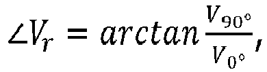

- It is easily understood that, the phase of the combined signal Sc output by the
combiner 118 may be adjusted by adjusting: - the amplitude of the first signal S1, noted V90° in the relation above, and/or
- the amplitude of the second signal S2, noted V0° in the relation above.
- The amplitude of the combined signal Sc output by the
combiner 118 may also be adjusted by adjusting: - the amplitude of the first signal S1, noted V90° in the relation above, and/or
- the amplitude of the second signal S2, noted V0° in the relation above.
- The
modulator 100 also comprises aglobal phase shifter 120, and in particular a 0-360° adjustable andcontrollable phase shifter 120, applying a desired phase shift, PP, to the combined signal Sc and provide an output signal Sout corresponding to the input signal Sin with the desired phase shift PP, and optionally a desired amplitude shift. - Thus, in the
modulator 100, there is only needed a unique phase difference of 90° between the two ways, i.e. between the first signal S1 and the second signal S2, to obtain in phase quadrature signals. When the in phase quadrature signals are obtained a desired phase shift may be applied to the combined signal by adjusting the amplitude of the first and the second signals. Thus, the calibration of themodulator 100 is much easier and much less time consuming, compared to the systems of the prior art combining a phase shifter and an attenuator, the systems requiring calibration for different values of phase shift between the two ways. - It is noted that, in the
modulator 100, for the first signal S1, theindividual phase shifter 110 applies a phase change to the first signal S1, in order to obtain a 90° phase difference with respect to second signal S2. With a perfect phase shifter, theindividual phase shifter 110 should not introduce an amplitude change to first signal S1. In fact, thephase shifter 110 introduces a small amplitude change to the first signal S1. Theattenuator 112 may be used to make up the amplitude change introduced by theindividual phase shifter 110. Also, a perfect attenuator should not introduce a phase shift to the first signal. But in real conditions, theindividual attenuator 112 introduces a small phase change. Theindividual phase shifter 110 may then be used to make up the small phase change introduced in the first signal by theindividual attenuator 112. This process may be repeated several times, for example 2 or 3 times, to calibrate thefirst path 106 of theassembly 104. - The same applies to the
second path 108 with theindividual phase shifter 114 and theindividual attenuator 116. - The calibration process is carried out until the first and the second paths are balanced so that, when the combination of the first and the second signals provides a combined signal with a phase of 45° +/- x°. This reduces the phase shift induced by the individual attenuators, and thus the overall calibration process of the
modulator 100. - Consequently, even if there is a need for calibrating the
individual phase shifters individual attenuators - Moreover, a perfect combiner should not introduce a phase change into the combined signal. Here again, with real combiners there is always a small phase change introduced in the combined signal. It is possible to make up the small phase change introduced by the
combiner 118 with theglobal phase shifter 120, during a calibrating phase. - Furthermore, a perfect global phase shifter should not modify the amplitude of the combined signal Sc. But, the
global phase shifter 120 will introduce a small amplitude change into the combined signal Sc. The small amplitude change may be made up with theindividual attenuators assembly 104. - An example of a calibration process that allows quick and easy calibration of the
modulator 200 will described further below. - The
modulator 100 of theFIGURE 1 may also comprise a controller for adjusting or controlling: - the phase shift PP applied to the input signal Sin, and
- optionally, the amplitude of the output signal Sout.
- To do this, the
controller 130 may be configured to control/adjust: - the phase shift applied by the
global phase shifter 120, and - the relative amplitude of the first and the second signal. For example, the controller may adjust/control the gain of at least one, and in particular each, of the
individual attenuators - In some embodiments, the
controller 130 may be configured to control theglobal phase shifter 120, eachindividual phase shifter individual attenuator - In the example shown in
FIGURE 1 theassembly 104 comprises an individual phase sifter and an individual attenuator for each of the first and second signals. - In other embodiments, the assembly may not comprise individual phase shifter and/or an individual attenuator of the first signal, or for the second signal.
-
FIGURE 2 is a diagrammatic representation of another non-limitative example of a modulator according to the present invention. - The
modulator 200, shown inFIGURE 2 , may be used to modulate the phase of a RF signal, and in particular of a microwave signal, Sin, in order to obtain an output signal, Sout, the phase of which is shifted. - The
modulator 200 comprises all the components of the modulator of theFIGURE 1 , except theindividual phase shifter 114. Thus, in the example ofFIGURE 2 , the phase shift of 90° between the first and the second signals S1 and S2 are obtained only through a phase shift applied to the first signal S1 by theindividual phase shifter 110. -
FIGURE 3 is a diagrammatic representation of a non-limitative example of a method according to the present invention. - The
method 300, shown inFIGURE 3 , may be used to modulate the phase of a RF signal, and in particular of a microwave signal, with a modulator according to the invention, and in particular with themodulator 100 ofFIGURE 1 or themodulator 200 ofFIGURE 2 . - The method comprises a
step 302 for splitting an input signal Sin into two signals: a first signal S1 and a second signal S2, with a splitter. - During a step 304 a phase shift is applied to at least one of the signals S1 and S2 in order to obtain a 90° phase difference between said first and second signals and delivering in phase quadrature first and second signals S1 and S2. The phase shift may be applied with an assembly comprising respective individual paths dedicated to each of the first signal S1 and second signal S2, as shown in
FIGURE 2 . Thestep 304 provides in phase quadrature signals S1 and S2. - At a
step 305, the amplitude of at least one, and in particular each, of the first and second signals S1 and S2 are adjusted, for example with at least one attenuator. - At a
step 306, the in phase quadrature signals S1 and S2 are combined with a combiner. - Finally, a phase shift is applied to the combined signals with a phase shifter at
step 308, in order to obtain the output signal. - As indicated above, the modulator according to the invention may need to be calibrated.
- The calibration phase described below, as a non-limitative example, may be used to calibrate the
modulator 200 ofFIGURE 2 . - The calibration phase may comprise the following steps:
- the individual phase shifters 202 and 206, and the individual attenuators 204 and 208, of the
first path 106 and thesecond path 108 are adjusted to obtain in phase quadrature first and second signals; - the two individual attenuators 204 and 208 of the first and the second paths are adjusted independently and the amplitude and the added phase shifting for a 90° phase difference is recorded for each
path - the individual phase shifters 202 and 206 are adjusted independently over a short range and the added amplitude is recorded;
- the range of the individual attenuators 204 and 208, and the range of the individual phase shifters 202 and 206 which could be used are determined by the added phase shifting and added amplitude depending on the required precision. The phase and the amplitude are controlled according to the following relations:


with ∠Vr the phase of the combined signal issued by the combiner and |Vr | the amplitude of the combined signal issued by the combiner; - the
global phase shifter 112 is adjusted, in particular over 0°-360° range, and the induced amplitude change is compensated by the individual phase shifters 202 and 206, and the individual attenuators 204 and 208. - Of course, the invention is not limited to the examples detailed above. The modulator, respectively the method, according to the invention may comprise other components, respectively features, than those indicated above.
Claims (13)
- A modulator (100;200) for modulating the phase and the amplitude of a radiofrequency signal (Sin), called input signal, said modulator (100;200) comprising:- a splitter (102) for splitting the input signal (Sin) into a first signal (S1) and a second signal (S2);- an assembly (104) comprising:▪ at least one individual phase shifter (110;114) for individually shifting the phase of at least one of the first and second signals (S1,S2) in order to obtain in phase quadrature first and second signals, and▪ at least one individual attenuator (112,116) for individually adjusting the amplitude of at least one of the first and second signals (S1,S2);- a combiner (118) for combining said in phase quadrature first and second signals (S1,S2) output by said assembly (104), and delivering a combined signal (Sc); and- a global phase shifter (120) for applying a phase shift to said combined signal (Sc) and delivering an output signal (Sout).
- The modulator (100;200) according to the preceding claim, characterized in that the global phase shifter (120) is an adjustable phase shifter.
- The modulator (100;200) according to any one of the preceding claims, characterized in that the global phase shifter (120) is a 0-360° phase shifter.
- The modulator (100;200) according to any one of the preceding claims, characterized in that the assembly (104) comprises a first path (106) dedicated to the first signal (S1) and a second path (S2) dedicated to the second signal (S2).
- The modulator (100;200) according to any one the preceding claims, characterized in that the assembly (104) comprises:- an individual phase shifter (110) for the first signal (S1), and- an individual phase shifter (114) for the second signal (S2).
- The modulator (100;200) according to the preceding claim, characterized in that at least one of the individual phase shifters (110,114) is an adjustable 0-360° phase shifter.
- The modulator (200) according to any one the preceding claims, characterized in that the assembly (104) comprises:- an individual attenuator (112) for the first signal (S1), and- an individual attenuator (116) for the second signal (S2);
- The modulator (100;200) according to the preceding claim, characterized in that at least one of the individual attenuators (112,116) is a controllable attenuator.
- The modulator (100;200) according to the preceding claim, characterized in that it also comprises a controller (130) for adjusting or controlling:- the phase shift applied to the input signal (Sin), and- optionally, the amplitude of the output signal (Sout).
- Use of a modulator (100;200) for simulating:- a direction of arrival of a received RF signal, or- a direction of emission of an emitted RF signal;by modulating the phase, and optionally the amplitude, of said RF signal.
- A method (300) for modulating the phase and the amplitude of a radiofrequency, RF, signal (Sin), called input signal, with a modulator (100;200) according to any one of the claims 1 to 9, said method (300) comprising the following steps:- splitting (302) the input signal (Sin) into a first signal (S1) and a second signal (S2);- phase shifting (304) for applying a 90° phase difference between said first and second signals (S1,S2) and delivering in phase quadrature first and second signals;- adjusting (305) amplitudes of said first and second signals (S1,S2),- combining (306) said in phase quadrature first and second signals and delivering a combined signal (Sc); and- applying (308) a phase shift to said combined signal (Sc) and delivering an output signal (Sout).
- The method (300) according to the preceding claim, further comprising a calibration phase of the modulator (100;200) for at least one desired phase shift value.
- A computer program comprising instructions, which when executed by a computer, cause the computer to carry out:- the steps of the method (300) according to any one of the claims 11 or 12; or- the functions carried out by the modulator (100;200) according to any one of the claims 1 to 9.
Priority Applications (1)
| Application Number | Priority Date | Filing Date | Title |
|---|---|---|---|
| EP22305818.1A EP4290766A1 (en) | 2022-06-06 | 2022-06-06 | A modulator and a method for modulating the phase of a radiofrequency signal |
Applications Claiming Priority (1)
| Application Number | Priority Date | Filing Date | Title |
|---|---|---|---|
| EP22305818.1A EP4290766A1 (en) | 2022-06-06 | 2022-06-06 | A modulator and a method for modulating the phase of a radiofrequency signal |
Publications (1)
| Publication Number | Publication Date |
|---|---|
| EP4290766A1 true EP4290766A1 (en) | 2023-12-13 |
Family
ID=82748698
Family Applications (1)
| Application Number | Title | Priority Date | Filing Date |
|---|---|---|---|
| EP22305818.1A Pending EP4290766A1 (en) | 2022-06-06 | 2022-06-06 | A modulator and a method for modulating the phase of a radiofrequency signal |
Country Status (1)
| Country | Link |
|---|---|
| EP (1) | EP4290766A1 (en) |
Citations (4)
| Publication number | Priority date | Publication date | Assignee | Title |
|---|---|---|---|---|
| WO1989012364A1 (en) * | 1988-06-10 | 1989-12-14 | Martin Communications Pty. Ltd. | Improvements relating to fading simulators |
| US5172394A (en) * | 1987-08-22 | 1992-12-15 | Spectrospin Ag | Method for reducing the content of spurious signals in the output signals of a mixer, and mixer for carrying out the method |
| US5504465A (en) * | 1992-11-18 | 1996-04-02 | Space Systems/Loral, Inc. | Microwave modulator having adjustable couplers |
| US9774299B2 (en) * | 2014-09-29 | 2017-09-26 | Nxp Usa, Inc. | Modifiable signal adjustment devices for power amplifiers and corresponding methods and apparatus |
-
2022
- 2022-06-06 EP EP22305818.1A patent/EP4290766A1/en active Pending
Patent Citations (4)
| Publication number | Priority date | Publication date | Assignee | Title |
|---|---|---|---|---|
| US5172394A (en) * | 1987-08-22 | 1992-12-15 | Spectrospin Ag | Method for reducing the content of spurious signals in the output signals of a mixer, and mixer for carrying out the method |
| WO1989012364A1 (en) * | 1988-06-10 | 1989-12-14 | Martin Communications Pty. Ltd. | Improvements relating to fading simulators |
| US5504465A (en) * | 1992-11-18 | 1996-04-02 | Space Systems/Loral, Inc. | Microwave modulator having adjustable couplers |
| US9774299B2 (en) * | 2014-09-29 | 2017-09-26 | Nxp Usa, Inc. | Modifiable signal adjustment devices for power amplifiers and corresponding methods and apparatus |
Similar Documents
| Publication | Publication Date | Title |
|---|---|---|
| US5862455A (en) | Fading simulator | |
| JPS63119339A (en) | Vector modulator calibrating method | |
| US11460542B2 (en) | Phase rotator calibration of a multichannel radar transmitter | |
| CN113079007A (en) | Intensity modulation method and intensity modulator for stable decoy state pulse | |
| US20210013602A1 (en) | Minimal phase matched test target injection for parallel receiver phase and amplitude alignment | |
| US4341999A (en) | High accuracy phase shift control system | |
| KR100564676B1 (en) | Feed forward amplifier improvement incorporating an automatic gain and phase controller | |
| KR100390073B1 (en) | Ultra-linear feedforward rf power amplifier | |
| CA3111011C (en) | Millimeter wave active load pull using low frequency phase and amplitude tuning | |
| US3480867A (en) | Adaptive receiver system for minimizing path intermodulation noise | |
| US6768390B1 (en) | System and method for generating balanced modulated signals with arbitrary amplitude and phase control using modulation | |
| JP3400736B2 (en) | Transmitter with training function | |
| US11812391B2 (en) | Systems, methods, and apparatus for combined power control of multiple transmit paths | |
| US6051996A (en) | Phase detector | |
| US11372084B2 (en) | Target signal generation | |
| CN116886257B (en) | Local oscillation adjusting method, equipment and medium of multichannel coherent signal source | |
| JP2004309472A (en) | System and method for calibrating a balanced signal | |
| US3568084A (en) | Circuit for controlling the frequency of a high frequency generator | |
| US3736530A (en) | Adjustable equalizer control apparatus | |
| DE112020006337B4 (en) | Phase shifter and antenna device | |
| JPH0583070A (en) | Phase control circuit | |
| SU205946A1 (en) | ||
| WO2026033227A1 (en) | Method and system for optical computing | |
| SU262211A1 (en) | METHOD OF ANIMATING STABLE CORRECTION FOR AUTOMATIC CONTROL SYSTEMS | |
| JPH0136072B2 (en) |
Legal Events
| Date | Code | Title | Description |
|---|---|---|---|
| PUAI | Public reference made under article 153(3) epc to a published international application that has entered the european phase |
Free format text: ORIGINAL CODE: 0009012 |
|
| STAA | Information on the status of an ep patent application or granted ep patent |
Free format text: STATUS: THE APPLICATION HAS BEEN PUBLISHED |
|
| AK | Designated contracting states |
Kind code of ref document: A1 Designated state(s): AL AT BE BG CH CY CZ DE DK EE ES FI FR GB GR HR HU IE IS IT LI LT LU LV MC MK MT NL NO PL PT RO RS SE SI SK SM TR |
|
| STAA | Information on the status of an ep patent application or granted ep patent |
Free format text: STATUS: REQUEST FOR EXAMINATION WAS MADE |
|
| P01 | Opt-out of the competence of the unified patent court (upc) registered |
Effective date: 20240227 |
|
| 17P | Request for examination filed |
Effective date: 20240321 |
|
| RBV | Designated contracting states (corrected) |
Designated state(s): AL AT BE BG CH CY CZ DE DK EE ES FI FR GB GR HR HU IE IS IT LI LT LU LV MC MK MT NL NO PL PT RO RS SE SI SK SM TR |