EP4290758A1 - Motor driving apparatus - Google Patents
Motor driving apparatus Download PDFInfo
- Publication number
- EP4290758A1 EP4290758A1 EP22208206.7A EP22208206A EP4290758A1 EP 4290758 A1 EP4290758 A1 EP 4290758A1 EP 22208206 A EP22208206 A EP 22208206A EP 4290758 A1 EP4290758 A1 EP 4290758A1
- Authority
- EP
- European Patent Office
- Prior art keywords
- motor driving
- switch
- windings
- changeover
- driving apparatus
- Prior art date
- Legal status (The legal status is an assumption and is not a legal conclusion. Google has not performed a legal analysis and makes no representation as to the accuracy of the status listed.)
- Pending
Links
Images




Classifications
-
- H—ELECTRICITY
- H02—GENERATION; CONVERSION OR DISTRIBUTION OF ELECTRIC POWER
- H02P—CONTROL OR REGULATION OF ELECTRIC MOTORS, ELECTRIC GENERATORS OR DYNAMO-ELECTRIC CONVERTERS; CONTROLLING TRANSFORMERS, REACTORS OR CHOKE COILS
- H02P25/00—Arrangements or methods for the control of AC motors characterised by the kind of AC motor or by structural details
- H02P25/16—Arrangements or methods for the control of AC motors characterised by the kind of AC motor or by structural details characterised by the circuit arrangement or by the kind of wiring
- H02P25/22—Multiple windings; Windings for more than three phases
-
- H—ELECTRICITY
- H02—GENERATION; CONVERSION OR DISTRIBUTION OF ELECTRIC POWER
- H02P—CONTROL OR REGULATION OF ELECTRIC MOTORS, ELECTRIC GENERATORS OR DYNAMO-ELECTRIC CONVERTERS; CONTROLLING TRANSFORMERS, REACTORS OR CHOKE COILS
- H02P25/00—Arrangements or methods for the control of AC motors characterised by the kind of AC motor or by structural details
- H02P25/16—Arrangements or methods for the control of AC motors characterised by the kind of AC motor or by structural details characterised by the circuit arrangement or by the kind of wiring
- H02P25/18—Arrangements or methods for the control of AC motors characterised by the kind of AC motor or by structural details characterised by the circuit arrangement or by the kind of wiring with arrangements for switching the windings, e.g. with mechanical switches or relays
-
- H—ELECTRICITY
- H02—GENERATION; CONVERSION OR DISTRIBUTION OF ELECTRIC POWER
- H02J—ELECTRIC POWER NETWORKS; CIRCUIT ARRANGEMENTS OR SYSTEMS FOR SUPPLYING OR DISTRIBUTING ELECTRIC POWER; SYSTEMS FOR STORING ELECTRIC ENERGY
- H02J9/00—Circuit arrangements for emergency or stand-by power supply, e.g. for emergency lighting
- H02J9/04—Circuit arrangements for emergency or stand-by power supply, e.g. for emergency lighting in which the distribution system is disconnected from the normal source and connected to a standby source
- H02J9/06—Circuit arrangements for emergency or stand-by power supply, e.g. for emergency lighting in which the distribution system is disconnected from the normal source and connected to a standby source with automatic change-over, e.g. UPS systems
-
- H—ELECTRICITY
- H02—GENERATION; CONVERSION OR DISTRIBUTION OF ELECTRIC POWER
- H02K—DYNAMO-ELECTRIC MACHINES
- H02K5/00—Casings; Enclosures; Supports
- H02K5/04—Casings or enclosures characterised by the shape, form or construction thereof
- H02K5/22—Auxiliary parts of casings not covered by groups H02K5/06-H02K5/20, e.g. shaped to form connection boxes or terminal boxes
- H02K5/225—Terminal boxes or connection arrangements
-
- H—ELECTRICITY
- H02—GENERATION; CONVERSION OR DISTRIBUTION OF ELECTRIC POWER
- H02M—APPARATUS FOR CONVERSION BETWEEN AC AND AC, BETWEEN AC AND DC, OR BETWEEN DC AND DC, AND FOR USE WITH MAINS OR SIMILAR POWER SUPPLY SYSTEMS; CONVERSION OF DC OR AC INPUT POWER INTO SURGE OUTPUT POWER; CONTROL OR REGULATION THEREOF
- H02M7/00—Conversion of AC power input into DC power output; Conversion of DC power input into AC power output
- H02M7/42—Conversion of DC power input into AC power output without possibility of reversal
- H02M7/44—Conversion of DC power input into AC power output without possibility of reversal by static converters
- H02M7/48—Conversion of DC power input into AC power output without possibility of reversal by static converters using discharge tubes with control electrode or semiconductor devices with control electrode
- H02M7/493—Conversion of DC power input into AC power output without possibility of reversal by static converters using discharge tubes with control electrode or semiconductor devices with control electrode the static converters being arranged for operation in parallel
-
- H—ELECTRICITY
- H02—GENERATION; CONVERSION OR DISTRIBUTION OF ELECTRIC POWER
- H02M—APPARATUS FOR CONVERSION BETWEEN AC AND AC, BETWEEN AC AND DC, OR BETWEEN DC AND DC, AND FOR USE WITH MAINS OR SIMILAR POWER SUPPLY SYSTEMS; CONVERSION OF DC OR AC INPUT POWER INTO SURGE OUTPUT POWER; CONTROL OR REGULATION THEREOF
- H02M7/00—Conversion of AC power input into DC power output; Conversion of DC power input into AC power output
- H02M7/42—Conversion of DC power input into AC power output without possibility of reversal
- H02M7/44—Conversion of DC power input into AC power output without possibility of reversal by static converters
- H02M7/48—Conversion of DC power input into AC power output without possibility of reversal by static converters using discharge tubes with control electrode or semiconductor devices with control electrode
- H02M7/53—Conversion of DC power input into AC power output without possibility of reversal by static converters using discharge tubes with control electrode or semiconductor devices with control electrode using devices of a triode or transistor type requiring continuous application of a control signal
- H02M7/537—Conversion of DC power input into AC power output without possibility of reversal by static converters using discharge tubes with control electrode or semiconductor devices with control electrode using devices of a triode or transistor type requiring continuous application of a control signal using semiconductor devices only, e.g. single switched pulse inverters
-
- H—ELECTRICITY
- H02—GENERATION; CONVERSION OR DISTRIBUTION OF ELECTRIC POWER
- H02P—CONTROL OR REGULATION OF ELECTRIC MOTORS, ELECTRIC GENERATORS OR DYNAMO-ELECTRIC CONVERTERS; CONTROLLING TRANSFORMERS, REACTORS OR CHOKE COILS
- H02P21/00—Arrangements or methods for the control of electric machines by vector control, e.g. by control of field orientation
- H02P21/22—Current control, e.g. using a current control loop
-
- H—ELECTRICITY
- H02—GENERATION; CONVERSION OR DISTRIBUTION OF ELECTRIC POWER
- H02P—CONTROL OR REGULATION OF ELECTRIC MOTORS, ELECTRIC GENERATORS OR DYNAMO-ELECTRIC CONVERTERS; CONTROLLING TRANSFORMERS, REACTORS OR CHOKE COILS
- H02P23/00—Arrangements or methods for the control of AC motors characterised by a control method other than vector control
- H02P23/0004—Control strategies in general, e.g. linear type, e.g. P, PI, PID, using robust control
- H02P23/0027—Control strategies in general, e.g. linear type, e.g. P, PI, PID, using robust control using different modes of control depending on a parameter, e.g. the speed
-
- H—ELECTRICITY
- H02—GENERATION; CONVERSION OR DISTRIBUTION OF ELECTRIC POWER
- H02P—CONTROL OR REGULATION OF ELECTRIC MOTORS, ELECTRIC GENERATORS OR DYNAMO-ELECTRIC CONVERTERS; CONTROLLING TRANSFORMERS, REACTORS OR CHOKE COILS
- H02P27/00—Arrangements or methods for the control of AC motors characterised by the kind of supply voltage
- H02P27/04—Arrangements or methods for the control of AC motors characterised by the kind of supply voltage using variable-frequency supply voltage, e.g. inverter or converter supply voltage
- H02P27/06—Arrangements or methods for the control of AC motors characterised by the kind of supply voltage using variable-frequency supply voltage, e.g. inverter or converter supply voltage using DC to AC converters or inverters
-
- H—ELECTRICITY
- H02—GENERATION; CONVERSION OR DISTRIBUTION OF ELECTRIC POWER
- H02P—CONTROL OR REGULATION OF ELECTRIC MOTORS, ELECTRIC GENERATORS OR DYNAMO-ELECTRIC CONVERTERS; CONTROLLING TRANSFORMERS, REACTORS OR CHOKE COILS
- H02P27/00—Arrangements or methods for the control of AC motors characterised by the kind of supply voltage
- H02P27/04—Arrangements or methods for the control of AC motors characterised by the kind of supply voltage using variable-frequency supply voltage, e.g. inverter or converter supply voltage
- H02P27/06—Arrangements or methods for the control of AC motors characterised by the kind of supply voltage using variable-frequency supply voltage, e.g. inverter or converter supply voltage using DC to AC converters or inverters
- H02P27/08—Arrangements or methods for the control of AC motors characterised by the kind of supply voltage using variable-frequency supply voltage, e.g. inverter or converter supply voltage using DC to AC converters or inverters with pulse width modulation
-
- H—ELECTRICITY
- H02—GENERATION; CONVERSION OR DISTRIBUTION OF ELECTRIC POWER
- H02P—CONTROL OR REGULATION OF ELECTRIC MOTORS, ELECTRIC GENERATORS OR DYNAMO-ELECTRIC CONVERTERS; CONTROLLING TRANSFORMERS, REACTORS OR CHOKE COILS
- H02P2207/00—Indexing scheme relating to controlling arrangements characterised by the type of motor
- H02P2207/07—Doubly fed machines receiving two supplies both on the stator only wherein the power supply is fed to different sets of stator windings or to rotor and stator windings
-
- H—ELECTRICITY
- H02—GENERATION; CONVERSION OR DISTRIBUTION OF ELECTRIC POWER
- H02P—CONTROL OR REGULATION OF ELECTRIC MOTORS, ELECTRIC GENERATORS OR DYNAMO-ELECTRIC CONVERTERS; CONTROLLING TRANSFORMERS, REACTORS OR CHOKE COILS
- H02P2209/00—Indexing scheme relating to controlling arrangements characterised by the waveform of the supplied voltage or current
- H02P2209/13—Different type of waveforms depending on the mode of operation
Definitions
- the present disclosure relates to a motor driving apparatus, and more specifically, to a motor driving apparatus including an inverter power module integrated with a switch which is switched according to a motor driving mode.
- windings of respective phases included in a motor have first ends electrically connected to a single inverter and have second ends electrically connected to each other, forming a Y-connection.
- a switch inside the inverter is turned ON/OFF by pulse width modulation control and applies a line voltage to the Y-connected motor windings such that, by generating an AC current, a torque is generated.
- An eco-friendly vehicle for example, electric car powered by such a torque from a motor has fuel efficiency (or electric efficiency) determined by inverter-motor power conversion efficiency, and it is important to maximize the inverter power conversion efficiency and the motor efficiency to improve the fuel efficiency.
- the efficiency of the inverter-motor system is mainly determined by the voltage usage ratio of the inverter, and the vehicle fuel efficiency may be improved when a vehicle driving point determined by the relation between the motor speed and torque is formed in a range having a high voltage usage ratio.
- the range having a high voltage usage ratio becomes far from the lowtorque area, which is a major vehicle driving point. This may degrade the fuel efficiency.
- a major driving point is designed to be included in the range having a high voltage usage ratio from the viewpoint of fuel efficiency, the maximum motor torque may be limited, degrading the accelerating/starting performance of the vehicle.
- Various aspects of the present disclosure are directed to providing a motor driving apparatus including an inverter power module integrated with a switch which is switched according to a motor driving mode.
- a motor driving apparatus may include: a motor including a plurality of windings respectively corresponding to a plurality of phases; a first inverter including at least one first power module and to provide an AC voltage corresponding to each of the phases to a first end of the plurality of windings; a second inverter including a plurality of second power modules each including a changeover switch and to provide the AC voltage corresponding to each of the phases to a second end of the plurality of windings based on information indicating whether the changeover switch is turned on; and a controller connected to the changeover switch and configured to control whether the changeover switch is turned on according to a motor driving mode, wherein each of the second power modules has a changeover terminal to which a first end of the changeover switch is connected, and the changeover terminals of the plurality of second power modules are short-circuited to each other.
- the present disclosure is advantageous in that an inverter power module is integrated with a switch which is switched according to a motor driving mode so that no separate module is necessary in connection with the switch which is switched according to a motor driving mode, reducing the area and cost required for a motor driving apparatus.
- the word "predetermined" as used herein means that a value for a parameter is determined when the parameter is used in a process or algorithm.
- the value for the parameter is determined before the process or algorithm begins or while the process or algorithm is performed.
- first and second used to distinguish various elements are not limited by the elements.
- a first component may be referred to as a second component, and conversely, a second component may be referred to as a first component.
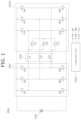
- FIG. 1 is a circuit diagram illustrating a motor driving apparatus 10a according to an exemplary embodiment of the present disclosure.
- the motor driving apparatus 10a may include a battery 100, a motor 200, a first inverter 300, a second inverter 400a, and a controller 500.
- the motor 200 may have a plurality of windings L1, L2, and L3 corresponding to each of a plurality of phases.
- the first inverter 300 may be implemented as at least one first power module 310, 320, and 330 in FIG. 4 including first top switches T1 to T3 and first bottom switches B1 to B3.
- the first inverter 300 may convert a DC voltage of the battery 100 into an AC voltage including a plurality of phases as the first top switches T1 to T3 and the first bottom switches B1 to B3 are switched. Furthermore, the first inverter 300 may drive the motor 200 by providing an AC voltage corresponding to each of the plurality of phases to one end of the plurality of windings L1, L2, and L3.
- the first top switches T1 to T3 and the first bottom switches B1 to B3 may be implemented as metal oxide semiconductor field effect transistors (MOSFETs).
- the second inverter 400a may be implemented as a plurality of second power modules 410a, 420a, and 430a of FIG. 4 including second top switches T4 to T6, second bottom switches B4 to B6, and changeover switches C1 to C3.
- the second inverter 400a may convert a DC voltage of the battery 100 into an AC voltage including a plurality of phases.
- the second inverter 400a may convert the DC voltage of the battery 100 into an AC voltage including a plurality of phases.
- the second inverter 400a may drive the motor 200 by providing the AC voltage corresponding to each of the plurality of phases to the other end of the plurality of windings L1, L2, and L3.
- the second top switches T4 to T6 and the second bottom switches B4 to B6 may be implemented as transistors including the same voltage/current capacity and material.
- the second top switches T4 to T6 and the second bottom switches B4 to B6 are implemented as insulated gate bipolar transistors (IGBTs), but according to the exemplary embodiment of the present disclosure, the second top switches T4 to T6 and the second bottom switches B4 to B6 may be implemented as metal oxide semiconductor field effect transistors (MOSFETs).
- Each of the changeover switches C1 to C3 may be equally implemented as any one of MOSFETs and IGBTs.
- the controller 500 may control the first inverter 300 and the second inverter 400a to drive the motor by switching the first top switches T1 to T3, the first bottom switches B1 to B3, the second top switches T4 to T6, and the second bottom switches B4 to B6.
- the controller 500 may control whether the changeover switches C1 to C3 provided in the second inverter 400a are turned on according to a motor driving mode.
- the motor driving mode may include a closed-end winding mode (CEW) and an open-end winding mode (OEW).
- CEW refers to a mode in which the other end of the plurality of windings L1, L2, and L3 included in the motor 200 form a neutral point, efficiently driving the motor only through the first inverter 300.
- the OEW refers to a mode in which the other end of the plurality of windings L1, L2, and L3 included in the motor 200 does not form the neutral point, increasing the driving force of the motor through not only the first inverter 300 but also the second inverter 400a.
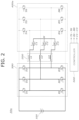
- FIG. 2 is a diagram illustrating a closed-end winding mode (CEW) performed in the motor driving apparatus 10a illustrated in FIG. 1 .
- CEW closed-end winding mode
- the controller 500 may turn on the changeover switches C1 to C3 so that the other end of the plurality of windings L1 to L3 form a neutral point (N).
- controller 500 may control the first inverter 300 to provide an AC voltage corresponding to a plurality of phases to one end of the plurality of windings L1, L2, and L3 by complementarily switching the first top switches T1 to T3 and the first bottom switches B1 to B3.
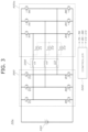
- FIG. 3 is a diagram illustrating an open-end winding mode (OEW) performed in the motor driving apparatus 10a illustrated in FIG. 1 .
- OEW open-end winding mode
- the controller 500 may turn off the changeover switches C1 to C3 so that the other end of the plurality of windings L1 to L3 does not form the neutral point.
- controller 500 may control the first inverter 300 and the second inverter 400a to provide the AC voltage corresponding to the plurality of phases to one end or the other end of the plurality of windings L1, L2, and L3 by complementarily switching the second top switches T4 to T6 and the second bottom switches B4 to B6 as well as the first top switches T1 to T3 and the first bottom switches B1 to B3.
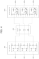
- FIG. 4 is a diagram illustrating a configuration of a power module included in the first inverter 300 and the second inverter 400a illustrated in FIG. 1 according to an exemplary embodiment of the present disclosure.
- the first inverter 300 may include a plurality of first power modules 310, 320, and 330
- the second inverter 400a may include a plurality of second power modules 410a, 420a, and 430a.
- the configuration and operation method of each of the plurality of first power modules 310, 320, and 330 are implemented in the same manner, and the configuration and operation method of each of the plurality of second power modules 410a, 420a, and 430a are implemented in the same manner.
- the first inverter 300 and the second inverter 400a may be respectively disposed on one side surface of a link capacitor used in the inverter and the other side surface thereof opposite to the one side thereof.
- Each of the plurality of first power modules 310, 320, 330 may include first top switches T1 to T3, first bottom switches B1 to B3, a positive terminal P electrically connected to the positive terminal (+) of the battery 100 of FIG. 1 , a negative terminal N electrically connected to the negative terminal (-) of the battery 100, and an output terminal O electrically connected to one end of any one of the plurality of windings L1 to L3.
- Each of the first top switches T1, T2, and T3 may be connected between the positive terminal P and the output terminal O
- each of the first bottom switches B1, B2, and B3 may be connected between the negative terminal N and the output terminal O.
- Each of the second power modules 410a, 420a, and 430a may include second top switches T4 to T6, second bottom switches B4 to B6, and changeover switches C1 to C3, and may have a positive terminal P electrically connected to the positive terminal (+) of the battery 100, a negative terminal N electrically connected to the negative terminal (-) of the battery 100, an output terminal O electrically connected to the other end of any one of the plurality of windings L1 to L3, and a changeover terminal C electrically connected to one end of the changeover switches C1 to C3.
- Each of the second top switches T4 to T6 may be connected between the positive terminal P and the output terminal O. Drain terminals (collector terminals) of the second top switches T4 to T6 may be respectively electrically connected to the positive terminal P, and source terminals (emitter terminals) of the second top switches T4 to T6 may be respectively electrically connected to the output terminal O.
- Each of the second bottom switches B4 to B6 may be connected between the negative terminal N and the output terminal O.
- the drain terminals (collector terminals) of the second bottom switches B4 to B6 may be respectively electrically connected to the output terminals O, and the source terminals (emitter terminals) of the second bottom switches B4 to B6 may be respectively electrically connected to the negative terminal (N).
- the source terminals (emitter terminals) of the changeover switches C1 to C3 may be respectively electrically connected to the output terminal O and located at the same node as the source terminals (emitter terminals) of the second top switches T4 to T6.
- the drain terminals (collector terminals) of the changeover switches C1 to C3 may be respectively electrically connected to the changeover terminal C.
- the changeover terminal C may be short-circuited to each other so that the other ends of the plurality of windings L1, L2, and L3 included in the motor form a neutral point.
- FIG. 5 is a diagram illustrating a configuration of the second power module 410a illustrated in FIG. 4 according to an exemplary embodiment of the present disclosure.
- the second power module 410a may include the second top switch T4, the second bottom switch B4, and the changeover switch C1.
- An output terminal O, a changeover terminal C, a negative terminal N, and a positive terminal P may be disposed on one side of the second power module 410a, and control pins PIN_B, PIN_C, and PIN_T may be disposed on the other side opposite to the one side of the second power module 410a.
- the second power module 410a may receive a signal for controlling a ON state or the like of the second top switch T4, the changeover switch C1, and the second bottom switch B4 through each of the control pin PIN_B, the control pin PIN_C, and the control pin PIN_T.
- control pin PIN_C for controlling the ON state of the changeover switch C1 and the control pin PIN_T for controlling the ON state of the second top switch T4 may be disposed adjacent to each other because they do not need to have an insulating distance therebetween, reducing the area of the second power module 410a.
- FIG. 6 is a circuit diagram illustrating a motor driving apparatus 10b according to another exemplary embodiment of the present disclosure.
- the motor driving apparatus 10b may include a battery 100, a motor 200, a first inverter 300, a second inverter 400b, and a controller 500.
- the second inverter 400b may be implemented as a plurality of second power modules 410b, 420b, and 430b of FIG. 8 including second top switches T4 to T6, second bottom switches B4 to B6, and changeover switches C1 to C3.
- the second inverter 400b may convert a DC voltage of the battery 100 into an AC voltage including a plurality of phases. Furthermore, the second inverter 400b may drive the motor 200 by providing the AC voltage corresponding to each of the plurality of phases to the other end of the plurality of windings L1, L2, and L3.
- FIG. 7 is a diagram illustrating a closed-end winding mode (CEW) performed in the motor driving apparatus 10b illustrated in FIG. 6 .
- CEW closed-end winding mode
- the controller 500 may turn off the changeover switches C1 to C3 and the second bottom switches B4 to B6 and turn on the second top switch T4 to T6, so that the other end of the plurality of windings L1 to L3 form a neutral point N.
- controller 500 may control the first inverter 300 to provide the AC voltage corresponding to the plurality of phases to one end of the plurality of windings L1, L2, and L3 by complementarily switching the first top switches T1 to T3 and the first bottom switches B1 to B3.
- FIG. 8 is a diagram illustrating an open-end winding mode (OEW) performed in the motor driving apparatus 10b illustrated in FIG. 6 .
- OEW open-end winding mode
- the controller 500 may turn on the changeover switches C1 to C3 so that the other end of the plurality of windings L1 to L3 does not form the neutral point.
- controller 500 may control the first inverter 300 and the second inverter 400b to provide the AC voltage corresponding to the plurality of phases to one end or the other end of the plurality of windings L1, L2, and L3 by complementarily switching the second top switches T4 to T6 and the second bottom switches B4 to B6 as well as the first top switches T1 to T3 and the first bottom switches B1 to B3.
- FIG. 9 is a diagram illustrating a configuration of the power module included in the first inverter 300 and the second inverter 400b illustrated in FIG. 6 according to an exemplary embodiment of the present disclosure.
- the second inverter 400b may include a plurality of second power modules 410b, 420b, and 430b.
- Each of the plurality of second power modules 410b, 420b, and 430b may include second top switches T4 to T6, second bottom switches B4 to B6, changeover switches C1 to C3, a positive terminal P electrically connected to the positive terminal (+) of the battery 100 of FIG. 6 , a negative terminal N electrically connected to the negative terminal (-) of the battery 100, an output terminal O electrically connected to the other end of any one of the plurality of windings L1 to L3, and a changeover terminal C electrically connected to one end of the changeover switches C1 to C3.
- each of the changeover switches C1 to C3 may be connected between the second top switches T4 to T6 and the positive terminal P while each of the second top switches T4 to T6 is connected between the positive terminal P and the output terminal O.
- drain terminals (collector terminals) of the changeover switches C1 to C3 may be respectively electrically connected to the positive terminal P
- source terminals (emitter terminals) of the changeover switches C1 to C3 may be respectively electrically connected to the changeover terminal C.
- the drain terminals (collector terminals) of the second top switches T4 to T6 may be located at the same node as the source terminals (emitter terminals) of the changeover switches C1 to C3, and the source terminals (emitter terminals) of the second top switches T4 to T6 may be electrically connected to the output terminal O.
- Each of the second bottom switches B4 to B6 may be connected between the negative terminal N and the output terminal O.
- the drain terminals (collector terminals) of the second bottom switches B4 to B6 may be respectively electrically connected to the output terminal O, and the source terminals (emitter terminals) of the second bottom switches B4 to B6 may be electrically connected to the negative terminal N.
- the changeover terminal C of each of the plurality of second power modules 410b, 420b, and 430b may be short-circuited to each other so that the other ends of the plurality of windings L1, L2, and L3 included in the motor form a neutral point.
- the changeover switches C1 to C3 that are switched according to the motor driving mode are integrated into each of the plurality of second power modules 410b, 420b, and 430b, there is no need to separately provide a module for the changeover switches C1 to C3, reducing the area and cost consumed in the motor driving apparatus 10b in FIG. 6 .
- FIG. 10 is a circuit diagram illustrating a motor driving apparatus 10c according to various exemplary embodiments of the present disclosure.
- the motor driving device 10c may include a battery 100, a motor 200, a first inverter 300, a second inverter 400c, and a controller 500.
- the second inverter 400c may be implemented as a plurality of second power modules (410c, 420c, and 430c of FIG. 13 ) including second top switches T4 to T6, second bottom switches B4 to B6, and changeover switches C1 to C3.
- the second inverter 400c may convert a DC voltage of the battery 100 into an AC voltage including a plurality of phases. Furthermore, the second inverter 400b may drive the motor 200 by providing the AC voltage corresponding to each of the plurality of phases to the other end of the plurality of windings L1, L2, and L3.
- FIG. 11 is a diagram illustrating a closed-end winding mode (CEW) performed in the motor driving apparatus 10c illustrated in FIG. 10 .
- CEW closed-end winding mode
- the controller 500 may turn off the changeover switches C1 to C3 and the second top switches T4 to T6 and turn on the second bottom switches B4 to B6, so that the other end of the plurality of windings L1 to L3 form a neutral point N.
- controller 500 may control the first inverter 300 to provide the AC voltage corresponding to the plurality of phases to one end of the plurality of windings L1, L2, and L3 by complementarily switching the first top switches T1 to T3 and the first bottom switches B1 to B3.
- FIG. 12 is a diagram illustrating an open-end winding mode (OEW) performed in the motor driving apparatus 10c illustrated in FIG. 10 .
- OEW open-end winding mode
- the controller 500 may turn on the changeover switches C1 to C3, so that the other end of the plurality of windings L1 to L3 does not form the neutral point.
- controller 500 may control the first inverter 300 and the second inverter 400c to provide the AC voltage corresponding to the plurality of phases to one end and the other end of the plurality of windings L1, L2, and L3 by complementarily switching the second top switches T4 to T6 and the second bottom switches B4 to B6 as well as the first top switches T1 to T3 and the first bottom switches B1 to B3.
- FIG. 13 is a diagram illustrating configurations of the inverters illustrated in FIG. 10 according to an exemplary embodiment of the present disclosure.
- the configuration and operation method of the first inverter 300 illustrated in FIG. 13 are implemented in the same manner as the first inverter 300 illustrated in FIG. 5 .
- the second inverter 400c may include a plurality of second power modules 410c, 420c, and 430c.
- Each of the plurality of second power modules 410c, 420c, and 430c may include second top switches T4 to T6, second bottom switches B4 to B6, changeover switches C1 to C3, a positive terminal P electrically connected to the positive terminal (+) of the battery 100 of FIG. 10 , a negative terminal N electrically connected to the negative terminal (-) of the battery 100, an output terminal O electrically connected to the other end of any one of the plurality of windings L1 to L3, and a changeover terminal C electrically connected to one end of the changeover switches C1 to C3.
- each of the changeover switches C1 to C3 may be connected between the second bottom switches B4 to B6 and the negative terminal N while each of the second bottom switches B4 to B6 is connected between the negative terminal N and the output terminal O.
- source terminals (emitter terminals) of the changeover switches C1 to C3 may be respectively electrically connected to the negative terminal N
- drain terminals (collector terminals) of the changeover switches C1 to C3 may be respectively electrically connected to the changeover terminal C.
- the source terminals (emitter terminals) of the second bottom switches B4 to B6 may be located at the same node as the drain terminals (collector terminals) of the changeover switches C1 to C3, and the drain terminals (collector terminals) of the second bottom switches B4 to B6 may be electrically connected to the output terminal O.
- Each of the second top switches T4 to T6 may be connected between the positive terminal P and the output terminal O.
- the drain terminals (collector terminals) of the second top switches T4 to T6 may be respectively electrically connected to the positive terminal P, and the source terminals (emitter terminals) of the second top switches T4 to T6 may be respectively electrically connected to the output terminal O.
- the respective changeover terminals C of the plurality of second power modules 410c, 420c, and 430c may be short-circuited to each other so that the other ends of the plurality of windings L1, L2, and L3 included in the motor form a neutral point.
- the changeover switches C1 to C3 that are switched according to the motor driving mode are integrated into each of the plurality of second power modules 410c, 420c, 430c, there is no need to separately provide a module for the changeover switches C1 to C3, reducing the area and cost consumed in the motor driving apparatus 10c in FIG. 10 .
- control device such as “controller”, “control apparatus”, “control unit”, “control device”, “control module”, or “server”, etc refers to a hardware device including a memory and a processor configured to execute one or more steps interpreted as an algorithm structure.
- the memory stores algorithm steps
- the processor executes the algorithm steps to perform one or more processes of a method in accordance with various exemplary embodiments of the present disclosure.
- the control device according to exemplary embodiments of the present disclosure may be implemented through a nonvolatile memory configured to store algorithms for controlling operation of various components of a vehicle or data about software commands for executing the algorithms, and a processor configured to perform operation to be described above using the data stored in the memory.
- the memory and the processor may be individual chips.
- the memory and the processor may be integrated in a single chip.
- the processor may be implemented as one or more processors.
- the processor may include various logic circuits and operation circuits, may process data according to a program provided from the memory, and may generate a control signal according to the processing result.
- the control device may be at least one microprocessor operated by a predetermined program which may include a series of commands for carrying out the method included in the aforementioned various exemplary embodiments of the present disclosure.
- the aforementioned invention can also be embodied as computer readable codes on a computer readable recording medium.
- the computer readable recording medium is any data storage device that can store data which may be thereafter read by a computer system and store and execute program instructions which may be thereafter read by a computer system.
- Examples of the computer readable recording medium include Hard Disk Drive (HDD), solid state disk (SSD), silicon disk drive (SDD), read-only memory (ROM), random-access memory (RAM), CD-ROMs, magnetic tapes, floppy discs, optical data storage devices, etc and implementation as carrier waves (e.g., transmission over the Internet).
- Examples of the program instruction include machine language code such as those generated by a compiler, as well as high-level language code which may be executed by a computer using an interpreter or the like.
- each operation described above may be performed by a control device, and the control device may be configured by a plurality of control devices, or an integrated single control device.
- control device may be implemented in a form of hardware or software, or may be implemented in a combination of hardware and software.
- unit for processing at least one function or operation, which may be implemented by hardware, software, or a combination thereof.
Landscapes
- Engineering & Computer Science (AREA)
- Power Engineering (AREA)
- Business, Economics & Management (AREA)
- Emergency Management (AREA)
- Control Of Ac Motors In General (AREA)
Abstract
Description
- The present disclosure relates to a motor driving apparatus, and more specifically, to a motor driving apparatus including an inverter power module integrated with a switch which is switched according to a motor driving mode.
- In general, windings of respective phases included in a motor have first ends electrically connected to a single inverter and have second ends electrically connected to each other, forming a Y-connection.
- When the motor is driven, a switch inside the inverter is turned ON/OFF by pulse width modulation control and applies a line voltage to the Y-connected motor windings such that, by generating an AC current, a torque is generated.
- An eco-friendly vehicle (for example, electric car) powered by such a torque from a motor has fuel efficiency (or electric efficiency) determined by inverter-motor power conversion efficiency, and it is important to maximize the inverter power conversion efficiency and the motor efficiency to improve the fuel efficiency.
- The efficiency of the inverter-motor system is mainly determined by the voltage usage ratio of the inverter, and the vehicle fuel efficiency may be improved when a vehicle driving point determined by the relation between the motor speed and torque is formed in a range having a high voltage usage ratio.
- However, if the motor winding number is increased to increase the motor maximum torque, the range having a high voltage usage ratio becomes far from the lowtorque area, which is a major vehicle driving point. This may degrade the fuel efficiency. In addition, if a major driving point is designed to be included in the range having a high voltage usage ratio from the viewpoint of fuel efficiency, the maximum motor torque may be limited, degrading the accelerating/starting performance of the vehicle.
- In the pertinent technical field, there is a demand for a motor driving technology capable of improving the system efficiency while covering both low-output and highoutput ranges with a single motor. As a result, a technology for driving a single motor in two different modes by use of two inserters and a mode-switching switch has been introduced.
- The information included in this Background of the present disclosure is only for enhancement of understanding of the general background of the present disclosure and may not be taken as an acknowledgement or any form of suggestion that this information forms the prior art already known to a person skilled in the art.
- Various aspects of the present disclosure are directed to providing a motor driving apparatus including an inverter power module integrated with a switch which is switched according to a motor driving mode.
- To solve the above-mentioned technical problem, a motor driving apparatus according to an exemplary embodiment of the present disclosure may include: a motor including a plurality of windings respectively corresponding to a plurality of phases; a first inverter including at least one first power module and to provide an AC voltage corresponding to each of the phases to a first end of the plurality of windings; a second inverter including a plurality of second power modules each including a changeover switch and to provide the AC voltage corresponding to each of the phases to a second end of the plurality of windings based on information indicating whether the changeover switch is turned on; and a controller connected to the changeover switch and configured to control whether the changeover switch is turned on according to a motor driving mode, wherein each of the second power modules has a changeover terminal to which a first end of the changeover switch is connected, and the changeover terminals of the plurality of second power modules are short-circuited to each other.
- The present disclosure is advantageous in that an inverter power module is integrated with a switch which is switched according to a motor driving mode so that no separate module is necessary in connection with the switch which is switched according to a motor driving mode, reducing the area and cost required for a motor driving apparatus.
- The methods and apparatuses of the present disclosure have other features and advantages which will be apparent from or are set forth in more detail in the accompanying drawings, which are incorporated herein, and the following Detailed Description, which together serve to explain certain principles of the present disclosure.
-
-
FIG. 1 is a circuit diagram illustrating a motor driving apparatus according to an exemplary embodiment of the present disclosure. -
FIG. 2 is a diagram illustrating a closed-end winding mode performed in the motor driving apparatus illustrated inFIG. 1 . -
FIG. 3 is a diagram illustrating an open-end winding mode performed in the motor driving apparatus illustrated inFIG. 1 . -
FIG. 4 is a diagram illustrating a configuration of a power module included in an inverter illustrated inFIG. 1 according to an exemplary embodiment of the present disclosure. -
FIG. 5 is a diagram illustrating a configuration of a second power module illustrated inFIG. 4 according to an exemplary embodiment of the present disclosure. -
FIG. 6 is a circuit diagram illustrating a motor driving apparatus according to another exemplary embodiment of the present disclosure. -
FIG. 7 is a diagram illustrating a closed-end winding mode performed in the motor driving apparatus illustrated inFIG. 6 . -
FIG. 8 is a diagram illustrating an open-end winding mode performed in the motor driving apparatus illustrated inFIG. 6 . -
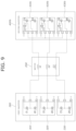
FIG. 9 is a diagram illustrating a configuration of a power module included in an inverter illustrated inFIG. 6 according to an exemplary embodiment of the present disclosure. -
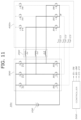
FIG. 10 is a circuit diagram illustrating a motor driving apparatus according to various exemplary embodiments of the present disclosure. -
FIG. 11 is a diagram illustrating a closed-end winding mode performed in the motor driving apparatus illustrated inFIG. 10 . -
FIG. 12 is a diagram illustrating an open-end winding mode performed in the motor driving apparatus illustrated inFIG. 10 . -
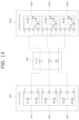
FIG. 13 is a diagram illustrating a configuration of a power module included in an inverter illustrated inFIG. 10 according to an exemplary embodiment of the present disclosure. - It may be understood that the appended drawings are not necessarily to scale, presenting a somewhat simplified representation of various features illustrative of the basic principles of the present disclosure. The specific design features of the present disclosure as included herein, including, for example, specific dimensions, orientations, locations, and shapes will be determined in part by the particularly intended application and use environment.
- In the figures, reference numbers refer to the same or equivalent portions of the present disclosure throughout the several figures of the drawing.
- Reference will now be made in detail to various embodiments of the present disclosure(s), examples of which are illustrated in the accompanying drawings and described below. While the present disclosure(s) will be described in conjunction with exemplary embodiments of the present disclosure, it will be understood that the present description is not intended to limit the present disclosure(s) to those exemplary embodiments of the present disclosure. On the other hand, the present disclosure(s) is/are intended to cover not only the exemplary embodiments of the present disclosure, but also various alternatives, modifications, equivalents and other embodiments, which may be included within the spirit and scope of the present disclosure as defined by the appended claims.
- In the description of the following embodiments, the word "predetermined" as used herein means that a value for a parameter is determined when the parameter is used in a process or algorithm. For various exemplary embodiments of the present disclosure, the value for the parameter is determined before the process or algorithm begins or while the process or algorithm is performed.
- Terms such as "first" and "second" used to distinguish various elements are not limited by the elements. For example, a first component may be referred to as a second component, and conversely, a second component may be referred to as a first component.
- It will be understood that when an element is referred to as being "connected" or "coupled" to another element, it may be directly connected or coupled to the other element or intervening elements may be present. In contrast, when an element is referred to as being "directly connected" or "directly coupled" to another element, there are no intervening elements present.
- Hereinafter, the present disclosure will be described in more detail through examples. These examples are only for illustrating the present disclosure, and the scope of protection of the rights of the present disclosure is not limited by these examples.
-
FIG. 1 is a circuit diagram illustrating amotor driving apparatus 10a according to an exemplary embodiment of the present disclosure. - As illustrated in
FIG. 1 , themotor driving apparatus 10a may include abattery 100, amotor 200, afirst inverter 300, asecond inverter 400a, and acontroller 500. - The
motor 200 may have a plurality of windings L1, L2, and L3 corresponding to each of a plurality of phases. - The
first inverter 300 may be implemented as at least onefirst power module FIG. 4 including first top switches T1 to T3 and first bottom switches B1 to B3. - The
first inverter 300 may convert a DC voltage of thebattery 100 into an AC voltage including a plurality of phases as the first top switches T1 to T3 and the first bottom switches B1 to B3 are switched. Furthermore, thefirst inverter 300 may drive themotor 200 by providing an AC voltage corresponding to each of the plurality of phases to one end of the plurality of windings L1, L2, and L3. The first top switches T1 to T3 and the first bottom switches B1 to B3 may be implemented as metal oxide semiconductor field effect transistors (MOSFETs). - The
second inverter 400a may be implemented as a plurality ofsecond power modules FIG. 4 including second top switches T4 to T6, second bottom switches B4 to B6, and changeover switches C1 to C3. - Based on whether the changeover switches C1 to C3 are turned on, as the second top switches T4 to T6 and the second bottom switches B4 to B6 are switched, the
second inverter 400a may convert a DC voltage of thebattery 100 into an AC voltage including a plurality of phases. In an exemplary embodiment of the present disclosure, when the changeover switches C1 to C3 are turned off, as the second top switches T4 to T6 and the second bottom switches B4 to B6 are switched, thesecond inverter 400a may convert the DC voltage of thebattery 100 into an AC voltage including a plurality of phases. Furthermore, thesecond inverter 400a may drive themotor 200 by providing the AC voltage corresponding to each of the plurality of phases to the other end of the plurality of windings L1, L2, and L3. - The second top switches T4 to T6 and the second bottom switches B4 to B6 may be implemented as transistors including the same voltage/current capacity and material. In an exemplary embodiment of the present disclosure, the second top switches T4 to T6 and the second bottom switches B4 to B6 are implemented as insulated gate bipolar transistors (IGBTs), but according to the exemplary embodiment of the present disclosure, the second top switches T4 to T6 and the second bottom switches B4 to B6 may be implemented as metal oxide semiconductor field effect transistors (MOSFETs).
- Each of the changeover switches C1 to C3 may be equally implemented as any one of MOSFETs and IGBTs.
- A detailed description of the configuration and operation method of the power module implementing the
first inverter 300 and thesecond inverter 400a will be described later with reference toFIG. 4 . - The
controller 500 may control thefirst inverter 300 and thesecond inverter 400a to drive the motor by switching the first top switches T1 to T3, the first bottom switches B1 to B3, the second top switches T4 to T6, and the second bottom switches B4 to B6. - Furthermore, the
controller 500 may control whether the changeover switches C1 to C3 provided in thesecond inverter 400a are turned on according to a motor driving mode. The motor driving mode may include a closed-end winding mode (CEW) and an open-end winding mode (OEW). The CEW refers to a mode in which the other end of the plurality of windings L1, L2, and L3 included in themotor 200 form a neutral point, efficiently driving the motor only through thefirst inverter 300. Conversely, the OEW refers to a mode in which the other end of the plurality of windings L1, L2, and L3 included in themotor 200 does not form the neutral point, increasing the driving force of the motor through not only thefirst inverter 300 but also thesecond inverter 400a. -
FIG. 2 is a diagram illustrating a closed-end winding mode (CEW) performed in themotor driving apparatus 10a illustrated inFIG. 1 . - As illustrated in
FIG. 2 , when the motor driving mode is set to the CEW, thecontroller 500 may turn on the changeover switches C1 to C3 so that the other end of the plurality of windings L1 to L3 form a neutral point (N). - Furthermore, the
controller 500 may control thefirst inverter 300 to provide an AC voltage corresponding to a plurality of phases to one end of the plurality of windings L1, L2, and L3 by complementarily switching the first top switches T1 to T3 and the first bottom switches B1 to B3. -
FIG. 3 is a diagram illustrating an open-end winding mode (OEW) performed in themotor driving apparatus 10a illustrated inFIG. 1 . - As illustrated in
FIG. 3 , when a motor driving mode is set to the OEW, thecontroller 500 may turn off the changeover switches C1 to C3 so that the other end of the plurality of windings L1 to L3 does not form the neutral point. - Furthermore, the
controller 500 may control thefirst inverter 300 and thesecond inverter 400a to provide the AC voltage corresponding to the plurality of phases to one end or the other end of the plurality of windings L1, L2, and L3 by complementarily switching the second top switches T4 to T6 and the second bottom switches B4 to B6 as well as the first top switches T1 to T3 and the first bottom switches B1 to B3. -
FIG. 4 is a diagram illustrating a configuration of a power module included in thefirst inverter 300 and thesecond inverter 400a illustrated inFIG. 1 according to an exemplary embodiment of the present disclosure. As illustrated inFIG. 4 , thefirst inverter 300 may include a plurality offirst power modules second inverter 400a may include a plurality ofsecond power modules first power modules second power modules first inverter 300 and thesecond inverter 400a may be respectively disposed on one side surface of a link capacitor used in the inverter and the other side surface thereof opposite to the one side thereof. - Each of the plurality of
first power modules battery 100 ofFIG. 1 , a negative terminal N electrically connected to the negative terminal (-) of thebattery 100, and an output terminal O electrically connected to one end of any one of the plurality of windings L1 to L3. Each of the first top switches T1, T2, and T3 may be connected between the positive terminal P and the output terminal O, each of the first bottom switches B1, B2, and B3 may be connected between the negative terminal N and the output terminal O. - Each of the
second power modules battery 100, a negative terminal N electrically connected to the negative terminal (-) of thebattery 100, an output terminal O electrically connected to the other end of any one of the plurality of windings L1 to L3, and a changeover terminal C electrically connected to one end of the changeover switches C1 to C3. - Each of the second top switches T4 to T6 may be connected between the positive terminal P and the output terminal O. Drain terminals (collector terminals) of the second top switches T4 to T6 may be respectively electrically connected to the positive terminal P, and source terminals (emitter terminals) of the second top switches T4 to T6 may be respectively electrically connected to the output terminal O.
- Each of the second bottom switches B4 to B6 may be connected between the negative terminal N and the output terminal O. The drain terminals (collector terminals) of the second bottom switches B4 to B6 may be respectively electrically connected to the output terminals O, and the source terminals (emitter terminals) of the second bottom switches B4 to B6 may be respectively electrically connected to the negative terminal (N).
- In an exemplary embodiment of the present disclosure, the source terminals (emitter terminals) of the changeover switches C1 to C3 may be respectively electrically connected to the output terminal O and located at the same node as the source terminals (emitter terminals) of the second top switches T4 to T6. The drain terminals (collector terminals) of the changeover switches C1 to C3 may be respectively electrically connected to the changeover terminal C. The changeover terminal C may be short-circuited to each other so that the other ends of the plurality of windings L1, L2, and L3 included in the motor form a neutral point. As the changeover switches C1 to C3 that are switched according to the motor driving mode are integrated into each of the plurality of
second power modules motor driving apparatus 10a inFIG. 1 . - Because the configurations of the
second power modules second power module 410a will be described below with reference toFIG. 5 . -
FIG. 5 is a diagram illustrating a configuration of thesecond power module 410a illustrated inFIG. 4 according to an exemplary embodiment of the present disclosure. As illustrated inFIG. 5 , thesecond power module 410a may include the second top switch T4, the second bottom switch B4, and the changeover switch C1. - An output terminal O, a changeover terminal C, a negative terminal N, and a positive terminal P may be disposed on one side of the
second power module 410a, and control pins PIN_B, PIN_C, and PIN_T may be disposed on the other side opposite to the one side of thesecond power module 410a. Thesecond power module 410a may receive a signal for controlling a ON state or the like of the second top switch T4, the changeover switch C1, and the second bottom switch B4 through each of the control pin PIN_B, the control pin PIN_C, and the control pin PIN_T. At the instant time, the control pin PIN_C for controlling the ON state of the changeover switch C1 and the control pin PIN_T for controlling the ON state of the second top switch T4 may be disposed adjacent to each other because they do not need to have an insulating distance therebetween, reducing the area of thesecond power module 410a. -
FIG. 6 is a circuit diagram illustrating amotor driving apparatus 10b according to another exemplary embodiment of the present disclosure. As illustrated inFIG. 6 , themotor driving apparatus 10b may include abattery 100, amotor 200, afirst inverter 300, asecond inverter 400b, and acontroller 500. - The
second inverter 400b may be implemented as a plurality ofsecond power modules FIG. 8 including second top switches T4 to T6, second bottom switches B4 to B6, and changeover switches C1 to C3. - In an exemplary embodiment of the present disclosure, when the changeover switches C1 to C3 are turned on, as the second top switches T4 to T6 and the second bottom switches B4 to B6 are switched, the
second inverter 400b may convert a DC voltage of thebattery 100 into an AC voltage including a plurality of phases. Furthermore, thesecond inverter 400b may drive themotor 200 by providing the AC voltage corresponding to each of the plurality of phases to the other end of the plurality of windings L1, L2, and L3. - A detailed description of the configuration and operation method of the power module implementing the
first inverter 300 and thesecond inverter 400b will be described later with reference toFIG. 9 . -
FIG. 7 is a diagram illustrating a closed-end winding mode (CEW) performed in themotor driving apparatus 10b illustrated inFIG. 6 . - As illustrated in
FIG. 7 , when the motor driving mode is set to the CEW, thecontroller 500 may turn off the changeover switches C1 to C3 and the second bottom switches B4 to B6 and turn on the second top switch T4 to T6, so that the other end of the plurality of windings L1 to L3 form a neutral point N. - Furthermore, the
controller 500 may control thefirst inverter 300 to provide the AC voltage corresponding to the plurality of phases to one end of the plurality of windings L1, L2, and L3 by complementarily switching the first top switches T1 to T3 and the first bottom switches B1 to B3. -
FIG. 8 is a diagram illustrating an open-end winding mode (OEW) performed in themotor driving apparatus 10b illustrated inFIG. 6 . - As illustrated in
FIG. 8 , when the motor driving mode is set to the OEW, thecontroller 500 may turn on the changeover switches C1 to C3 so that the other end of the plurality of windings L1 to L3 does not form the neutral point. - Furthermore, the
controller 500 may control thefirst inverter 300 and thesecond inverter 400b to provide the AC voltage corresponding to the plurality of phases to one end or the other end of the plurality of windings L1, L2, and L3 by complementarily switching the second top switches T4 to T6 and the second bottom switches B4 to B6 as well as the first top switches T1 to T3 and the first bottom switches B1 to B3. -
FIG. 9 is a diagram illustrating a configuration of the power module included in thefirst inverter 300 and thesecond inverter 400b illustrated inFIG. 6 according to an exemplary embodiment of the present disclosure. - Because the configuration and operation method of the
first inverter 300 illustrated inFIG. 9 are implemented in the same manner as thefirst inverter 300 illustrated inFIG. 4 , a detailed description thereof will be omitted. - The
second inverter 400b may include a plurality ofsecond power modules - Each of the plurality of
second power modules battery 100 ofFIG. 6 , a negative terminal N electrically connected to the negative terminal (-) of thebattery 100, an output terminal O electrically connected to the other end of any one of the plurality of windings L1 to L3, and a changeover terminal C electrically connected to one end of the changeover switches C1 to C3. - In an exemplary embodiment of the present disclosure, each of the changeover switches C1 to C3 may be connected between the second top switches T4 to T6 and the positive terminal P while each of the second top switches T4 to T6 is connected between the positive terminal P and the output terminal O. drain terminals (collector terminals) of the changeover switches C1 to C3 may be respectively electrically connected to the positive terminal P, and source terminals (emitter terminals) of the changeover switches C1 to C3 may be respectively electrically connected to the changeover terminal C. The drain terminals (collector terminals) of the second top switches T4 to T6 may be located at the same node as the source terminals (emitter terminals) of the changeover switches C1 to C3, and the source terminals (emitter terminals) of the second top switches T4 to T6 may be electrically connected to the output terminal O.
- Each of the second bottom switches B4 to B6 may be connected between the negative terminal N and the output terminal O. The drain terminals (collector terminals) of the second bottom switches B4 to B6 may be respectively electrically connected to the output terminal O, and the source terminals (emitter terminals) of the second bottom switches B4 to B6 may be electrically connected to the negative terminal N.
- The changeover terminal C of each of the plurality of
second power modules second power modules motor driving apparatus 10b inFIG. 6 . -
FIG. 10 is a circuit diagram illustrating amotor driving apparatus 10c according to various exemplary embodiments of the present disclosure. As illustrated inFIG. 10 , themotor driving device 10c may include abattery 100, amotor 200, afirst inverter 300, asecond inverter 400c, and acontroller 500. - The
second inverter 400c may be implemented as a plurality of second power modules (410c, 420c, and 430c ofFIG. 13 ) including second top switches T4 to T6, second bottom switches B4 to B6, and changeover switches C1 to C3. - In the present exemplary embodiment of the present disclosure, similarly to the
second inverter 400b illustrated inFIG. 6 , when the changeover switches C1 to C3 are turned on, as the second top switches T4 to T6 and the second bottom switches B4 to B6 are switched, thesecond inverter 400c may convert a DC voltage of thebattery 100 into an AC voltage including a plurality of phases. Furthermore, thesecond inverter 400b may drive themotor 200 by providing the AC voltage corresponding to each of the plurality of phases to the other end of the plurality of windings L1, L2, and L3. - A detailed description of the configuration and operation method of the power module implementing the
first inverter 300 and thesecond inverter 400c will be described later with reference toFIG. 13 . -
FIG. 11 is a diagram illustrating a closed-end winding mode (CEW) performed in themotor driving apparatus 10c illustrated inFIG. 10 . - As illustrated in
FIG. 11 , when the motor driving mode is set to the CEW, thecontroller 500 may turn off the changeover switches C1 to C3 and the second top switches T4 to T6 and turn on the second bottom switches B4 to B6, so that the other end of the plurality of windings L1 to L3 form a neutral point N. - Furthermore, the
controller 500 may control thefirst inverter 300 to provide the AC voltage corresponding to the plurality of phases to one end of the plurality of windings L1, L2, and L3 by complementarily switching the first top switches T1 to T3 and the first bottom switches B1 to B3. -
FIG. 12 is a diagram illustrating an open-end winding mode (OEW) performed in themotor driving apparatus 10c illustrated inFIG. 10 . - As illustrated in
FIG. 12 , when the motor driving mode is set to the OEW, thecontroller 500 may turn on the changeover switches C1 to C3, so that the other end of the plurality of windings L1 to L3 does not form the neutral point. - Furthermore, the
controller 500 may control thefirst inverter 300 and thesecond inverter 400c to provide the AC voltage corresponding to the plurality of phases to one end and the other end of the plurality of windings L1, L2, and L3 by complementarily switching the second top switches T4 to T6 and the second bottom switches B4 to B6 as well as the first top switches T1 to T3 and the first bottom switches B1 to B3. -
FIG. 13 is a diagram illustrating configurations of the inverters illustrated inFIG. 10 according to an exemplary embodiment of the present disclosure. - The configuration and operation method of the
first inverter 300 illustrated inFIG. 13 are implemented in the same manner as thefirst inverter 300 illustrated inFIG. 5 . - The
second inverter 400c may include a plurality ofsecond power modules - Each of the plurality of
second power modules battery 100 ofFIG. 10 , a negative terminal N electrically connected to the negative terminal (-) of thebattery 100, an output terminal O electrically connected to the other end of any one of the plurality of windings L1 to L3, and a changeover terminal C electrically connected to one end of the changeover switches C1 to C3. - In the present exemplary embodiment of the present disclosure, each of the changeover switches C1 to C3 may be connected between the second bottom switches B4 to B6 and the negative terminal N while each of the second bottom switches B4 to B6 is connected between the negative terminal N and the output terminal O. source terminals (emitter terminals) of the changeover switches C1 to C3 may be respectively electrically connected to the negative terminal N, and drain terminals (collector terminals) of the changeover switches C1 to C3 may be respectively electrically connected to the changeover terminal C. The source terminals (emitter terminals) of the second bottom switches B4 to B6 may be located at the same node as the drain terminals (collector terminals) of the changeover switches C1 to C3, and the drain terminals (collector terminals) of the second bottom switches B4 to B6 may be electrically connected to the output terminal O.
- Each of the second top switches T4 to T6 may be connected between the positive terminal P and the output terminal O. The drain terminals (collector terminals) of the second top switches T4 to T6 may be respectively electrically connected to the positive terminal P, and the source terminals (emitter terminals) of the second top switches T4 to T6 may be respectively electrically connected to the output terminal O.
- The respective changeover terminals C of the plurality of
second power modules second power modules motor driving apparatus 10c inFIG. 10 . - Furthermore, the term related to a control device such as "controller", "control apparatus", "control unit", "control device", "control module", or "server", etc refers to a hardware device including a memory and a processor configured to execute one or more steps interpreted as an algorithm structure. The memory stores algorithm steps, and the processor executes the algorithm steps to perform one or more processes of a method in accordance with various exemplary embodiments of the present disclosure. The control device according to exemplary embodiments of the present disclosure may be implemented through a nonvolatile memory configured to store algorithms for controlling operation of various components of a vehicle or data about software commands for executing the algorithms, and a processor configured to perform operation to be described above using the data stored in the memory. The memory and the processor may be individual chips. Alternatively, the memory and the processor may be integrated in a single chip. The processor may be implemented as one or more processors. The processor may include various logic circuits and operation circuits, may process data according to a program provided from the memory, and may generate a control signal according to the processing result.
- The control device may be at least one microprocessor operated by a predetermined program which may include a series of commands for carrying out the method included in the aforementioned various exemplary embodiments of the present disclosure.
- The aforementioned invention can also be embodied as computer readable codes on a computer readable recording medium. The computer readable recording medium is any data storage device that can store data which may be thereafter read by a computer system and store and execute program instructions which may be thereafter read by a computer system. Examples of the computer readable recording medium include Hard Disk Drive (HDD), solid state disk (SSD), silicon disk drive (SDD), read-only memory (ROM), random-access memory (RAM), CD-ROMs, magnetic tapes, floppy discs, optical data storage devices, etc and implementation as carrier waves (e.g., transmission over the Internet). Examples of the program instruction include machine language code such as those generated by a compiler, as well as high-level language code which may be executed by a computer using an interpreter or the like.
- In various exemplary embodiments of the present disclosure, each operation described above may be performed by a control device, and the control device may be configured by a plurality of control devices, or an integrated single control device.
- In various exemplary embodiments of the present disclosure, the control device may be implemented in a form of hardware or software, or may be implemented in a combination of hardware and software.
- Furthermore, the terms such as "unit", "module", etc. included in the specification mean units for processing at least one function or operation, which may be implemented by hardware, software, or a combination thereof.
- For convenience in explanation and accurate definition in the appended claims, the terms "upper", "lower", "inner", "outer", "up", "down", "upwards", "downwards", "front", "rear", "back", "inside", "outside", "inwardly", "outwardly", "interior", "exterior", "internal", "external", "forwards", and "backwards" are used to describe features of the exemplary embodiments with reference to the positions of such features as displayed in the figures. It will be further understood that the term "connect" or its derivatives refer both to direct and indirect connection.
- The foregoing descriptions of specific exemplary embodiments of the present disclosure have been presented for purposes of illustration and description. They are not intended to be exhaustive or to limit the present disclosure to the precise forms disclosed, and obviously many modifications and variations are possible in light of the above teachings. The exemplary embodiments were chosen and described in order to explain certain principles of the invention and their practical application, to enable others skilled in the art to make and utilize various exemplary embodiments of the present disclosure, as well as various alternatives and modifications thereof. It is intended that the scope of the present disclosure be defined by the Claims appended hereto and their equivalents.
Claims (14)
- A motor driving apparatus comprising:a motor including a plurality of windings respectively corresponding to a plurality of phases;a first inverter including at least one first power module and configured to provide an alternating current (AC) voltage corresponding to each of the phases to a first end of the plurality of windings;a second inverter including a plurality of second power modules each including a changeover switch and configured to provide the AC voltage corresponding to each of the phases to a second end of the plurality of windings based on information indicating whether the changeover switch is turned on; anda controller connected to the changeover switch and configured to control whether the changeover switch is turned on according to a motor driving mode,wherein each of the second power modules has a changeover terminal to which a first end of the changeover switch is connected, andwherein the changeover terminals of the plurality of second power modules are short-circuited to each other.
- The motor driving apparatus of claim 1, wherein the controller is configured to:control whether the changeover switch is turned on so that the second end of the plurality of windings form a neutral point when the motor driving mode is set to a closed-end winding mode, andcontrol whether the changeover switch is turned on so that the second end of the plurality of windings does not form the neutral point when the motor driving mode is set to an open-end winding mode.
- The motor driving apparatus of claim 1, wherein the at least one first power mode includes:a first top switch;a first bottom switch;a positive terminal electrically connected to a positive terminal of a battery;a negative terminal electrically connected to a negative terminal of the battery; andan output terminal electrically connected to a first end of one of the plurality of windings,wherein the first top switch is connected between the positive terminal and the output terminal, andwherein the first bottom switch is connected between the negative terminal and the output terminal.
- The motor driving apparatus of claim 3, wherein the controller is configured to complementarily switch the first top switch and the first bottom switch.
- The motor driving apparatus of claim 3, wherein the first top switch and the first bottom switch are implemented as metal oxide semiconductor field effect transistors (MOSFETs).
- The motor driving apparatus of claim 1, wherein each of the second power modules includes:a second top switch;a second bottom switch;a positive terminal electrically connected to a positive terminal of a battery;a negative terminal electrically connected to a negative terminal of the battery; andan output terminal electrically connected to a second end of one of the plurality of windings,wherein the second top switch is connected between the positive terminal and the output terminal, andwherein the second bottom switch is connected between the negative terminal and the output terminal.
- The motor driving apparatus of claim 6, wherein the second top switch and the second bottom switch are identically implemented as one of a metal oxide semiconductor field effect transistor (MOSFET) and an insulated gate bipolar transistor (IGBT).
- The motor driving apparatus of claim 6, wherein the respective changeover switches are identically implemented as one of an MOSFET and an IGBT.
- The motor driving apparatus of claim 6, wherein a second end of the changeover switch is electrically connected to the output terminals of the plurality of second power modules, respectively.
- The motor driving apparatus of claim 9, wherein the controller is configured to:turn on the changeover switch so that the second end of the plurality of windings form a neutral point when the motor driving mode is set to a closed-end winding mode, andturn off the changeover switch so that the second end of the plurality of windings does not form the neutral point when the motor driving mode is set to an open-end winding mode.
- The motor driving apparatus of claim 6,wherein a second end of the changeover switch is electrically connected to the positive terminals of the plurality of second power modules, respectively, andwherein the second top switch is connected between the first end of the changeover switch and the output terminal.
- The motor driving apparatus of claim 11, wherein the controller is configured to:turn on the second top switch and turn off the second bottom switch and the changeover switch so that the second end of the plurality of windings form a neutral point when the motor driving mode is set to a closed-end winding mode, andturn on the changeover switch so that the second end of the plurality of windings does not the neutral point when the motor driving mode is set to an open-end winding mode.
- The motor driving apparatus of claim 6,wherein each of the changeover switches is electrically connected to the negative terminal of the plurality of second power modes, andwherein the second bottom switch is connected between the first end of the changeover switch and the output terminal.
- The motor driving apparatus of claim 13, wherein the controller is configured to:turn on the second bottom switch and turn off the second top switch and the changeover switch so that the second end of the plurality of windings forms a neutral point when the motor driving mode is set to a closed-end winding mode, andturn on the changeover switch so that the second end of the plurality of windings does not the neutral point when the motor driving mode is set to an open-end winding mode.
Applications Claiming Priority (1)
| Application Number | Priority Date | Filing Date | Title |
|---|---|---|---|
| KR1020220070039A KR20230169643A (en) | 2022-06-09 | 2022-06-09 | Motor driving apparatus |
Publications (1)
| Publication Number | Publication Date |
|---|---|
| EP4290758A1 true EP4290758A1 (en) | 2023-12-13 |
Family
ID=84360465
Family Applications (1)
| Application Number | Title | Priority Date | Filing Date |
|---|---|---|---|
| EP22208206.7A Pending EP4290758A1 (en) | 2022-06-09 | 2022-11-18 | Motor driving apparatus |
Country Status (4)
| Country | Link |
|---|---|
| US (1) | US12381504B2 (en) |
| EP (1) | EP4290758A1 (en) |
| KR (1) | KR20230169643A (en) |
| CN (1) | CN117220540A (en) |
Families Citing this family (1)
| Publication number | Priority date | Publication date | Assignee | Title |
|---|---|---|---|---|
| KR20240018936A (en) | 2022-08-03 | 2024-02-14 | 현대자동차주식회사 | Power module |
Citations (4)
| Publication number | Priority date | Publication date | Assignee | Title |
|---|---|---|---|---|
| US20050162875A1 (en) * | 2003-12-17 | 2005-07-28 | Pablo Rodriguez | Architecture for power modules such as power inverters |
| US20190372501A1 (en) * | 2016-12-26 | 2019-12-05 | Nidec Corporation | Power conversion device, motor drive unit, and electric power steering device |
| CN111355420A (en) * | 2020-04-16 | 2020-06-30 | 广东美的制冷设备有限公司 | Motor drive control circuit, drive method, circuit board and air conditioner |
| US20220173687A1 (en) * | 2020-11-27 | 2022-06-02 | Hyundai Motor Company | Motor driving apparatus and method |
Family Cites Families (19)
| Publication number | Priority date | Publication date | Assignee | Title |
|---|---|---|---|---|
| KR20050003732A (en) * | 2003-07-04 | 2005-01-12 | 현대자동차주식회사 | A vector-controlled dual inverter system for an induction motor |
| JP2005318690A (en) | 2004-04-27 | 2005-11-10 | Sanyo Electric Co Ltd | Inverter module |
| JP2005328675A (en) | 2004-05-17 | 2005-11-24 | Sanyo Electric Co Ltd | Inverter module |
| JP4876661B2 (en) * | 2006-03-24 | 2012-02-15 | 株式会社デンソー | Electric generator for vehicle |
| EP2008853B1 (en) * | 2007-06-25 | 2010-09-15 | Mazda Motor Corporation | Hybrid vehicle |
| US8002056B2 (en) * | 2007-07-30 | 2011-08-23 | GM Global Technology Operations LLC | Double-ended inverter system with isolated neutral topology |
| FR2936380B1 (en) * | 2008-09-24 | 2010-10-29 | Messier Bugatti | ELECTRIC ACTUATOR WHICH INCLUDES TWO CURRENT VOLTAGE INVERTERS SUPPLYING AN ELECTRICAL MACHINE AND WHICH IS RECONFIGURABLE IN THE PRESENCE OF A FAULT |
| JP5150570B2 (en) | 2009-06-30 | 2013-02-20 | 株式会社日立製作所 | Three-phase power converter |
| DE102010060380B3 (en) * | 2010-11-05 | 2012-02-02 | Lti Drives Gmbh | Emergency-operated pitch motor drive circuit |
| DE102012203528A1 (en) * | 2012-03-06 | 2013-09-12 | Bayerische Motoren Werke Aktiengesellschaft | Vehicle with electric machine and method of operating this |
| ITMI20122053A1 (en) * | 2012-11-30 | 2014-05-31 | Mavel Srl | ELECTRIC MACHINE INCLUDING AN ALTERNATING CURRENT ELECTRIC MOTOR AND AN INVERTER |
| WO2015087553A1 (en) * | 2013-12-13 | 2015-06-18 | 日本精工株式会社 | Electronic control unit, electric power steering device, and vehicle |
| KR20140022933A (en) | 2014-01-17 | 2014-02-25 | 페어차일드코리아반도체 주식회사 | Three-phase inverter package |
| JP2016048997A (en) | 2014-08-28 | 2016-04-07 | 株式会社明電舎 | Control method and device for power conversion system |
| US10355581B2 (en) * | 2015-09-22 | 2019-07-16 | Schlumberger Technology Corporation | Fault tolerant inverter or controlled rectifier system |
| US9852859B2 (en) * | 2015-12-28 | 2017-12-26 | Qualcomm Incorporated | Adjustable power rail multiplexing |
| KR102489298B1 (en) | 2016-01-28 | 2023-01-17 | 엘지이노텍 주식회사 | Inverter package |
| KR101956991B1 (en) | 2016-11-25 | 2019-03-12 | 현대자동차주식회사 | Method for controlling dual inverter |
| US10581361B2 (en) | 2017-01-17 | 2020-03-03 | Ford Global Technologies, Llc | Multiple inverter system for an electric machine |
-
2022
- 2022-06-09 KR KR1020220070039A patent/KR20230169643A/en active Pending
- 2022-11-11 US US17/985,354 patent/US12381504B2/en active Active
- 2022-11-18 EP EP22208206.7A patent/EP4290758A1/en active Pending
- 2022-12-02 CN CN202211539615.2A patent/CN117220540A/en active Pending
Patent Citations (4)
| Publication number | Priority date | Publication date | Assignee | Title |
|---|---|---|---|---|
| US20050162875A1 (en) * | 2003-12-17 | 2005-07-28 | Pablo Rodriguez | Architecture for power modules such as power inverters |
| US20190372501A1 (en) * | 2016-12-26 | 2019-12-05 | Nidec Corporation | Power conversion device, motor drive unit, and electric power steering device |
| CN111355420A (en) * | 2020-04-16 | 2020-06-30 | 广东美的制冷设备有限公司 | Motor drive control circuit, drive method, circuit board and air conditioner |
| US20220173687A1 (en) * | 2020-11-27 | 2022-06-02 | Hyundai Motor Company | Motor driving apparatus and method |
Also Published As
| Publication number | Publication date |
|---|---|
| CN117220540A (en) | 2023-12-12 |
| KR20230169643A (en) | 2023-12-18 |
| US20230402951A1 (en) | 2023-12-14 |
| US12381504B2 (en) | 2025-08-05 |
Similar Documents
| Publication | Publication Date | Title |
|---|---|---|
| US12403784B2 (en) | Vehicle battery charging system using motor driving system | |
| US11722088B2 (en) | Motor driving system | |
| US12034392B2 (en) | Apparatus and method for driving motor | |
| US11394210B2 (en) | Charging system | |
| US12176768B2 (en) | Motor driving apparatus | |
| US11545923B2 (en) | Motor driving apparatus and method | |
| US12199540B2 (en) | Motor driving apparatus | |
| US12199544B2 (en) | Motor driving apparatus and method | |
| US20230253907A1 (en) | Motor driving apparatus | |
| US20230253909A1 (en) | Motor driving apparatus | |
| US12381504B2 (en) | Motor driving apparatus | |
| US12479331B2 (en) | Electrified vehicle and method for controlling the same | |
| JP5303295B2 (en) | Power converter for vehicle and electric vehicle | |
| US12101046B2 (en) | Motor driving apparatus | |
| US12227080B2 (en) | Motor driving system and method of controlling same | |
| JP2022118417A (en) | Power supply system | |
| US12470163B2 (en) | Power module | |
| US12337701B2 (en) | Electrified vehicle and method of controlling same | |
| JP4655056B2 (en) | Driving device for switching element | |
| JP7063179B2 (en) | Control circuit | |
| US20240305183A1 (en) | Gate driving device and method of controlling electrified vehicle including same | |
| US11876469B2 (en) | Single motor with dual inverters using voltage vector | |
| JP6327063B2 (en) | Power supply | |
| JP2025167406A (en) | Power conversion device, drive system, control device, and control program |
Legal Events
| Date | Code | Title | Description |
|---|---|---|---|
| PUAI | Public reference made under article 153(3) epc to a published international application that has entered the european phase |
Free format text: ORIGINAL CODE: 0009012 |
|
| STAA | Information on the status of an ep patent application or granted ep patent |
Free format text: STATUS: THE APPLICATION HAS BEEN PUBLISHED |
|
| AK | Designated contracting states |
Kind code of ref document: A1 Designated state(s): AL AT BE BG CH CY CZ DE DK EE ES FI FR GB GR HR HU IE IS IT LI LT LU LV MC ME MK MT NL NO PL PT RO RS SE SI SK SM TR |
|
| P01 | Opt-out of the competence of the unified patent court (upc) registered |
Effective date: 20231221 |
|
| STAA | Information on the status of an ep patent application or granted ep patent |
Free format text: STATUS: REQUEST FOR EXAMINATION WAS MADE |
|
| 17P | Request for examination filed |
Effective date: 20240516 |
|
| RBV | Designated contracting states (corrected) |
Designated state(s): AL AT BE BG CH CY CZ DE DK EE ES FI FR GB GR HR HU IE IS IT LI LT LU LV MC ME MK MT NL NO PL PT RO RS SE SI SK SM TR |
|
| STAA | Information on the status of an ep patent application or granted ep patent |
Free format text: STATUS: EXAMINATION IS IN PROGRESS |
|
| 17Q | First examination report despatched |
Effective date: 20250617 |