EP4290698A1 - Antenna arrangement - Google Patents
Antenna arrangement Download PDFInfo
- Publication number
- EP4290698A1 EP4290698A1 EP22382543.1A EP22382543A EP4290698A1 EP 4290698 A1 EP4290698 A1 EP 4290698A1 EP 22382543 A EP22382543 A EP 22382543A EP 4290698 A1 EP4290698 A1 EP 4290698A1
- Authority
- EP
- European Patent Office
- Prior art keywords
- reflector
- antenna
- frequency range
- conductive element
- reflective surface
- Prior art date
- Legal status (The legal status is an assumption and is not a legal conclusion. Google has not performed a legal analysis and makes no representation as to the accuracy of the status listed.)
- Pending
Links
- 238000000034 method Methods 0.000 description 8
- 239000003989 dielectric material Substances 0.000 description 3
- 238000004519 manufacturing process Methods 0.000 description 3
- 229920000747 poly(lactic acid) Polymers 0.000 description 3
- 239000004626 polylactic acid Substances 0.000 description 3
- 230000009471 action Effects 0.000 description 2
- 239000000654 additive Substances 0.000 description 2
- 230000000996 additive effect Effects 0.000 description 2
- 230000001413 cellular effect Effects 0.000 description 2
- 238000004891 communication Methods 0.000 description 2
- 230000007774 longterm Effects 0.000 description 2
- 239000000463 material Substances 0.000 description 2
- 238000010295 mobile communication Methods 0.000 description 2
- 230000010287 polarization Effects 0.000 description 2
- 230000009467 reduction Effects 0.000 description 2
- 230000000007 visual effect Effects 0.000 description 2
- 230000003190 augmentative effect Effects 0.000 description 1
- 230000001808 coupling effect Effects 0.000 description 1
- 230000009977 dual effect Effects 0.000 description 1
- 230000000694 effects Effects 0.000 description 1
- 230000036541 health Effects 0.000 description 1
- 230000001404 mediated effect Effects 0.000 description 1
- 230000004048 modification Effects 0.000 description 1
- 238000012986 modification Methods 0.000 description 1
- 230000003287 optical effect Effects 0.000 description 1
- 238000009877 rendering Methods 0.000 description 1
- 239000000758 substrate Substances 0.000 description 1
- 230000001360 synchronised effect Effects 0.000 description 1
Images


Classifications
-
- H—ELECTRICITY
- H01—ELECTRIC ELEMENTS
- H01Q—ANTENNAS, i.e. RADIO AERIALS
- H01Q19/00—Combinations of primary active antenna elements and units with secondary devices, e.g. with quasi-optical devices, for giving the antenna a desired directional characteristic
- H01Q19/10—Combinations of primary active antenna elements and units with secondary devices, e.g. with quasi-optical devices, for giving the antenna a desired directional characteristic using reflecting surfaces
- H01Q19/12—Combinations of primary active antenna elements and units with secondary devices, e.g. with quasi-optical devices, for giving the antenna a desired directional characteristic using reflecting surfaces wherein the surfaces are concave
- H01Q19/17—Combinations of primary active antenna elements and units with secondary devices, e.g. with quasi-optical devices, for giving the antenna a desired directional characteristic using reflecting surfaces wherein the surfaces are concave the primary radiating source comprising two or more radiating elements
-
- H—ELECTRICITY
- H01—ELECTRIC ELEMENTS
- H01Q—ANTENNAS, i.e. RADIO AERIALS
- H01Q21/00—Antenna arrays or systems
- H01Q21/06—Arrays of individually energised antenna units similarly polarised and spaced apart
- H01Q21/08—Arrays of individually energised antenna units similarly polarised and spaced apart the units being spaced along or adjacent to a rectilinear path
-
- H—ELECTRICITY
- H01—ELECTRIC ELEMENTS
- H01Q—ANTENNAS, i.e. RADIO AERIALS
- H01Q21/00—Antenna arrays or systems
- H01Q21/06—Arrays of individually energised antenna units similarly polarised and spaced apart
- H01Q21/20—Arrays of individually energised antenna units similarly polarised and spaced apart the units being spaced along or adjacent to a curvilinear path
-
- H—ELECTRICITY
- H01—ELECTRIC ELEMENTS
- H01Q—ANTENNAS, i.e. RADIO AERIALS
- H01Q21/00—Antenna arrays or systems
- H01Q21/24—Combinations of antenna units polarised in different directions for transmitting or receiving circularly and elliptically polarised waves or waves linearly polarised in any direction
-
- H—ELECTRICITY
- H01—ELECTRIC ELEMENTS
- H01Q—ANTENNAS, i.e. RADIO AERIALS
- H01Q21/00—Antenna arrays or systems
- H01Q21/28—Combinations of substantially independent non-interacting antenna units or systems
-
- H—ELECTRICITY
- H01—ELECTRIC ELEMENTS
- H01Q—ANTENNAS, i.e. RADIO AERIALS
- H01Q25/00—Antennas or antenna systems providing at least two radiating patterns
-
- H—ELECTRICITY
- H01—ELECTRIC ELEMENTS
- H01Q—ANTENNAS, i.e. RADIO AERIALS
- H01Q5/00—Arrangements for simultaneous operation of antennas on two or more different wavebands, e.g. dual-band or multi-band arrangements
- H01Q5/40—Imbricated or interleaved structures; Combined or electromagnetically coupled arrangements, e.g. comprising two or more non-connected fed radiating elements
-
- H—ELECTRICITY
- H01—ELECTRIC ELEMENTS
- H01Q—ANTENNAS, i.e. RADIO AERIALS
- H01Q9/00—Electrically-short antennas having dimensions not more than twice the operating wavelength and consisting of conductive active radiating elements
- H01Q9/04—Resonant antennas
- H01Q9/0407—Substantially flat resonant element parallel to ground plane, e.g. patch antenna
Definitions
- Embodiments of the present disclosure relate to an antenna arrangement.
- an antenna arrangement comprising:
- the at least one conductive element is positioned between the reflector and at least one receiving and/or radiating element of the first antenna.
- the at least one conductive element is supported by the reflector.
- At least a plurality of points of a perimeter of the at least one conductive element is substantially at a fixed distance from the reflector.
- the fixed distance is substantially n times ⁇ /2, wherein n is a positive integer and A is a wavelength that corresponds to a frequency of the first frequency range.
- the at least one conductive element is configured to receive and/or radiate in a plurality of frequencies within the second frequency range and/or in a plurality of polarisations.
- the first frequency range is located at frequencies that are substantially higher than the respective frequencies of the second frequency range.
- the first frequency range does not overlap with the second frequency range.
- At least one of the at least one conductive element has a shape that is conforming to the reflective surface of the reflector.
- the at least one conductive element comprises a plurality of conductive elements, and one or more of the conductive elements of the plurality of conductive elements has or have a shape that is substantially conforming to the reflective surface of the reflector.
- the reflective surface is substantially parabolic in shape and the plurality of conductive elements is configured in a substantially parabolic shape.
- the antenna arrangement is configured to allow different pointing directions for the first and second antennas.
- one or more feed lines to the at least one conductive element pass through at least one opening in the reflector.
- one or more feed lines to the at least one conductive element run across the reflective surface of the reflector.
- an apparatus comprising an antenna arrangement as described herein.
- an antenna arrangement comprising:
- the figures illustrate examples of an antenna arrangement 10 for operation in a first and a second frequency range.
- the antenna arrangement 10 comprises:
- conductive is used to refer to electrical conductivity, that is, capable of transferring a direct electrical current.
- the frequency range of an antenna is the range over which it is considered to provide a satisfactory performance, such as a useful level of signal strength or sufficiently high antenna efficiency or gain.
- a frequency range can in turn be divided into smaller sub-ranges, for example, into frequency bands that represent definitive intervals in the frequency domain and that are official intervals defined by standardization bodies.
- FIG. 1 schematically illustrates an example of an antenna arrangement 10.
- FIG. 1 Various features referenced in the discussion of FIG. 1 can be found in the other FIGs. Furthermore, during the discussion of FIG. 1 , reference will be made to other FIGs. By way of example.
- the antenna arrangement 10 comprises a first antenna 12 configured to operate in a first frequency range and a second antenna 14 configured to operate in a second frequency range.
- the first frequency range can be considered higher relative to the second frequency range and, similarly, the second frequency range can be considered lower relative to the first frequency range.
- the first antenna 12 is configured to operate in at least one higher frequency band and the second antenna 14 is configured to operate in at least one lower frequency band.
- the first antenna 12 is configured to operate in at least one first frequency band and the second antenna 14 is configured to operate in at least one second frequency band, the first frequency band being of higher frequencies than the second frequency band.
- the first frequency range and the second frequency range can at least partially overlap.
- the at least one higher frequency band and the at least one lower frequency band can at least partially overlap.
- the first frequency range is located at frequencies that are substantially higher that the respective frequencies of the second frequency range. Accordingly, in examples, the upper frequency of the first frequency range is substantially higher than the upper frequency of the second frequency range and the lower frequency of the first frequency range is substantially higher than the lower frequency of the second frequency range.
- the first frequency range does not overlap with the second frequency range. In examples, it can be considered that the first frequency range does not have and/or does not exhibit an overlap with the second frequency range.
- the first antenna 12 can be configured to operate in any suitable higher frequency band or bands and/or the second antenna 14 can be configured to operate in any suitable lower frequency band or bands.
- the first antenna 12 can be configured to operate in at least one higher frequency band in the range 25GHz to 30GHz and/or the second antenna 14 can be configured to operate in at least one lower frequency band in the range 2.1GHz to 4GHz.
- the first antenna 12 and/or second antenna 14 can have any suitable configuration and/or form.
- the first antenna 12 can have any suitable configuration and/or form to operate in the range 25GHz to 30GHz and/or the second antenna 14 can have any suitable configuration and/or form to operate in the range 2.1GHz to 4GHz.
- the first antenna 12 can, in some examples, be considered a millimeter wave antenna.
- the first antenna 12 comprises a reflector 16 configured to provide a reflective surface 18 at, at least, the first frequency range.
- the reflector 16 can be considered an antenna reflector.
- the reflector 16 can have any suitable size, and/or shape, and/or form, and/or configuration to provide a reflective surface 18 at, at least, the first frequency range.
- the reflective surface 18 can comprise any suitable surface or surfaces of the reflector 16.
- the reflective surface 18 can be considered a portion of the reflector 16.
- the reflector 16 can have any suitable size, and/or shape, and/or form, and/or configuration to provide a reflective surface 18 configured to direct and/or reflect electromagnetic waves at, at least, the first frequency range, to and/or from at least one receiving and/or radiating element 22 of the first antenna 12.
- the at least one receiving and/or radiating element 22 can be considered an antenna feed.
- the reflector 16 is configured to direct and/or reflect electromagnetic waves at, at least, the first frequency range, to and/or from at least one receiving and/or radiating element 22 of the first antenna 12.
- the reflector 16 can have any suitable size, and/or shape, and/or form, and/or configuration to provide a reflective surface 18 to add gain to the first frequency range.
- reflector 16 and/or the reflective surface 18 is substantially parabolic in shape.
- the reflective surface 18 of the reflector 16 can be considered a surface from which electromagnetic waves are reflected to/from at least one receiving and/or radiating element 22 of the first antenna 12.
- FIG. 4 schematically illustrates an antenna arrangement 10 comprising a first antenna 12 and a second antenna 14.
- the reflector 16 is substantially parabolic in shape and is configured to provide a reflective surface 18 that is substantially parabolic in shape.
- the reflective surface 18, of the reflector 16 is configured to direct electromagnetic waves to/from the receiving and/or radiating element 22 of the first antenna 12.
- the second antenna 14 comprises at least one conductive element 20 configured to receive and/or radiate in the second frequency range, wherein at least a portion of the at least one conductive element 20 is configured to act as at least a portion of the reflective surface 18 of the reflector 16.
- FIG. 1 illustrates an antenna arrangement 10 comprising,
- the at least one conductive element 20 can have any suitable shape, and/or size, and/or form and/or configuration to receive and/or radiate in the second frequency range and to act as at least a portion of the reflective surface 18 of the reflector 16.
- the at least one conductive element can comprise one or more patch antennas and/or, in some examples, can comprise one or more slots and so on.
- the at least one conductive element can be rectangular, square, circular, cross shaped and so on.
- different ones of the at least one conductive element 20 can have different shapes, and/or sizes, and/or forms, and/or configurations and so on.
- the at least one conductive element 20 is configured to resonate in the second frequency range.
- the reflector 16 can act as a ground plane for the at least one conductive element 20.
- the at least one conductive element 20 is configured to receive and/or radiate in the second frequency range and also to function as at least a portion of the reflective surface 18 of the reflector 16.
- the at least one conductive element 20 is configured to substantially replace at least a portion of the reflective surface 18 of the reflector 16.
- At least a portion of the at least one conductive element 20 is configured to reflect electromagnetic waves to and/or from at least one receiving and/or radiating element 22 of the first antenna 12.
- At least one conductive element 20 is configured to reflect electromagnetic waves to a point substantially corresponding to a focus of the reflector 16.
- the at least one conductive element 20 is configured to not substantially affect the performance of the first antenna 12 in the first frequency range.
- the at least one conductive element 20 is configured to allow electromagnetic waves reflected from the conductive element 20 and from the reflective surface 18 of the reflector 16 to be in phase.
- the at least one conductive element 20 can be configured and/or arranged in any suitable way.
- the at least one conductive element 20 is positioned between the reflector 16 and at least one receiving and/or radiating element 22 of the first antenna 12.
- the antenna arrangement 10 comprises a conductive element 20 positioned between the reflector 16 and receiving and/or radiating element 22 of the first antenna 12.
- the at least one conductive element 20 can be supported and/or held in any suitable way.
- the at least one conductive element 20 is supported by the reflector 16.
- the at least one conductive element 20 can be supported using dielectric material(s) between the at least one conductive element 20 and the reflector 16. See, for example, FIG. 6A .
- Air can be used as a dielectric between the at least one conductive element 20 and the reflector 16.
- the at least one conductive element 20 can, for example, be supported by one or more columns of dielectric material.
- one or more feed lines of the at least one conductive element 20 can be used to support the at least one conductive element 20.
- the at least one conductive element 20 can be fed from behind the reflector 16 and the feed line(s) used to support the at least one conductive element 20.
- the size of the at least one conductive element 20 can be configured based, at least in part, on the permittivity of the dielectric(s) used, to allow the at least one conductive element to receive and/or radiate in the second frequency range.
- At least a plurality of points of a perimeter of the at least one conductive element 20 is at a fixed distance 24 from the reflector 16.
- At least a plurality of points of a perimeter of the at least one conductive element 20 is at a fixed distance 24 from the reflector 16 to allow the at least one conductive element 20 to act as at least a portion of the reflective surface 18 of the reflector 16.
- At least a plurality of points of a perimeter of the at least one conductive element 20 is substantially at a fixed distance 24 from the reflector 16 in a direction towards at least one receiving and/or radiating element 22 of the first antenna 12.
- FIG. 3A schematically illustrates an example of a cross section through a conductive element 20 and a reflector 16 configured to provide a reflective surface 18.
- the conductive element 20 is at a fixed distance 24 from the reflector 16.
- the support(s) for the conductive element 20 are not shown.
- a receiving and/or radiating element 22 of the first antenna 12 is generally to the left of the figure and therefore the conductive element 20 is at a fixed distance 24 from the reflector 16 in a direction generally towards the receiving and/or radiating element 22 of the first antenna 12.
- the conductive element 20 has a shape that is conforming to the shape of the reflective surface 18 of the reflector 16. Accordingly, in the example of FIG. 3A , the perimeter of the conductive element 20 is at a fixed distance 24 from the reflector 16 as the shape of the conductive element 20 is conforming to the shape of the reflective surface 18 of the reflector 16.
- any suitable selected points of the perimeter of the at least one conductive element 20 can be at a fixed distance 24 from the reflector 16.
- the centers of the at least one conductive element's edges can be at a fixed distance 24 from the reflector 16.
- the fixed distance 24 is substantially n times ⁇ /2, wherein n is a positive integer and A is a wavelength that corresponds to a frequency of the first frequency range.
- A is a wavelength that corresponds to a resonant frequency of the first frequency range.
- A is a wavelength that corresponds to a center frequency of the first frequency range.
- the conductive element 20 is at a fixed distance 24 from the reflector 16 and is configured to act as a portion of the reflective surface 18 of the reflector 16.
- the conductive element 20 has a shape that is conforming to reflective surface 18 of the reflector 16 and is therefore also parabolic in shape.
- the perimeter of the conductive element 20 is substantially at a fixed distance 24 from the reflector 16.
- the conductive element 20 is located at 5mm ( ⁇ /2 of a frequency of the first frequency range) distance from the reflector 16. This allows for an integer number of A round trips so that the waves reflected by the reflector 16 and the waves reflected by the conductive element 20 are in phase.
- the at least one conductive element 20 is configured to receive and/or radiate in a plurality of frequencies within the second frequency range and/or in a plurality of polarisations.
- the at least one conductive element 20 is configured to resonate in a plurality of frequencies within the second frequency range.
- the at least one conductive element 20 can have any suitable form and/or shape and/or size and/or configuration to receive and/or radiate in a plurality of frequencies within the second frequency range and/or in a plurality of polarisations.
- the at least one conductive element 20 can comprise one or more slots. See, for example, FIG. 7 .
- At least one of the at least one conductive element 20 has a shape that is conforming to the reflective surface 18 of the reflector 16.
- a conductive element 20 has a shape that is conforming to the reflective surface 18 of the reflector 16 if the shape of the conductive element 20 matches, and/or follows, and/or is in line with, and/or mirrors the shape of the reflective surface 18 of the reflector 16.
- a conductive element 20 has a shape that is conforming to the reflective surface 18 of the reflector 16 if the perimeter of the conductive element 20 is at a substantially fixed distance 24 from the reflective surface 18 of the reflector 16.
- the conductive element 20 has a substantially parabolic shape and the reflector 16, and reflective surface 18, also has a substantially parabolic shape such that the conductive element 20 has a shape that is conforming to the reflective surface 18 of the reflector 16 and the perimeter of the conductive element 20 is at a fixed distance 24 from the reflector 16.
- An element or elements that has/have a shape that is conforming to the shape of another element can be considered to have a shape that conforms to the shape of the other element.
- the conductive element 20 in the example of FIG. 4 can be considered to have a shape that conforms to the reflective surface 18 of the reflector 16.
- the at least one conductive element 20 comprises a plurality of conductive elements 20, and the plurality of conductive elements 20 is configured in a shape that is substantially conforming to the reflective surface 18 of the reflector 16.
- the plurality of conductive elements 20 can be considered a group of conductive elements 20.
- a group of conductive elements 20 is configured/arranged in a shape that is substantially conforming to the reflective surface 18 of the reflector 16.
- the group of conductive elements 20 can be configured/arranged in a mosaic having a shape that is substantially conforming to the reflective surface 18 of the reflector 16.
- One or more of the conductive elements 20 of the plurality of conductive elements 20 can have a shape that is substantially conforming to the reflective surface 18 of the reflector 16 and/or one or more of the conductive elements 20 of the plurality of conductive elements 20 can have a shape that is substantially non-conforming to the reflective surface 18 of the reflector 16.
- one or more of the conductive elements 20 of the plurality of conductive elements 20 has a shape that is substantially non-conforming to the reflective surface 18 of the reflector 16.
- the reflective surface 18 of the reflector 16 can have a curved shape but one or more of the conductive elements 20 of the plurality of conductive elements can be substantially flat and arranged in a shape that is substantially conforming to the curved shape of the reflective surface 27 of the reflector 16.
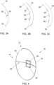
- FIG. 3B By way of example, reference is made to FIG. 3B .
- FIG. 3B is similar to the example of FIG. 3A , and similarly schematically illustrates a cross-section of a reflector 16 having a reflective surface 18 and associated conductive elements 20.
- a dashed line 28 is present indicating a curve that is conforming to the shape of the reflective surface 18 of the reflector 16.
- the plurality of conductive elements 20 are substantially flat and are therefore non-conforming to the shape of the reflective surface 18. However, the conductive elements 20 are arranged in a shape that is substantially conforming to the shape of the reflective surface 18.
- a plurality of conductive elements 20, that are substantially non-conforming to the reflective surface 18 of the reflector 16 are arranged in a shape that is substantially conforming to the reflective surface 18 of the reflector 16 if a plurality of points of the individual conductive elements 20 lie on a surface that has a shape that is conforming to the shape of the reflective surface 18 of the reflector 16.
- a plurality of conductive elements 20, that are substantially non-conforming to the reflective surface 18 of the reflector 16 are arranged in a shape that is substantially conforming to the reflective surface 18 of the reflector 16 if at least a plurality of points of a perimeter of the conductive elements 20 lie on a surface having a shape that is conforming to the shape of the reflective surface 18 of the reflector 16.
- a plurality of points of the perimeter of the individual conductive elements 20, but not all of the perimeter, are substantially at a fixed distance from the reflector 16.
- the plurality of conductive elements 20 is configured in a shape that is substantially conforming to the reflective surface 18 of the reflector 16 and one or more of the conductive elements 20 of the plurality of conductive elements 20 has a shape that is substantially conforming to the reflective surface 18 of the reflector 16.
- FIG. 3C By way of example, reference is made to FIG. 3C .
- FIG. 3C is similar to the example of FIG. 3B .
- the group of conductive elements 20 is configured in a shape that is substantially conforming to the reflective surface 18 of the reflector 16 and the individual conductive elements 20 are also substantially conforming to the reflective surface 18 of the reflector 16.
- the perimeter of the individual conductive elements 20 is substantially at a fixed distance from the reflector 16.
- the reflective surface 18 is substantially parabolic in shape and the plurality of conductive elements is configured in a substantially parabolic shape.
- the antenna arrangement 10 is configured to allow different pointing directions for the first and second antennas 12, 14.
- the antenna arrangement 10 is configured to allow different boresights for the first and second antennas 12, 14.
- the antenna arrangement 10 can be configured in any suitable way to allow different pointing directions for the first and second antennas 12, 14.
- the antenna arrangement 10 can be configured to allow different combinations of phases to be applied to feeds of at least one conductive element 20 to point the beam at the second frequency range to an arbitrary direction independently to the pointing of the first antenna 12 at the first frequency range.
- the at least one receiving and/or radiating element 22 of the first antenna 12, in combination with a shape in the reflector 16/reflecting surface 18, can point to an arbitrary direction independently of the second antenna 14.
- the pointing direction of the first antenna 12 in the first frequency range can be kept fixed at zero degrees and simultaneously the beam of the second antenna 14 in the second frequency range can point to other directions.
- the at least one conductive element 20 can be fed in any suitable way using any suitable method.
- one or more feed lines can be provided to the conductive element 20.
- one or more feed lines to the at least one conductive element 20 pass through at least one opening in the reflector 16.
- one or more feed lines to the at least one conductive element 20 run across the reflective surface 27 of the reflector 16.
- feed lines to at least once conductive element 20 that run across the reflective surface 18 of the reflector 16 can be configured to act as at least a portion of the reflective surface 18 of the reflector 16 as described in relation to the one or more conductive elements 20.
- FIG. 2 schematically illustrates an example of an apparatus 26.
- the apparatus 26 can be considered an electronic device.
- the apparatus 26 comprises an antenna arrangement 10 as described herein.
- FIG. 2 illustrates in the example of an apparatus comprising an antenna arrangement 10 as described herein.
- the apparatus 26 can comprise a customer premises equipment (CPE).
- CPE customer premises equipment
- FIG. 5 illustrates an example of an antenna arrangement 10.
- the example of FIG. 5 is similar to the example of FIG. 4 .
- the second antenna 14 comprises a plurality of conductive elements 20 configured to receive and/or radiate in the second frequency range.
- the plurality of conductive elements has a shape that is substantially conforming to the reflective surface 18 of the reflector 10 and the individual conductive elements 20 also have shapes that are conforming to the reflective surface 18 of the reflector 16.
- FIG. 6A illustrates an example of an antenna arrangement 10.
- the antenna arrangement 10 comprises a first antenna 12 comprising a reflector 16 configured to provide a reflective surface 18, and a plurality of receiving and/or radiating elements 22.
- the reflector 16 in the example of FIG. 6A , has a parabolic shape and focal shift.
- the first antenna 12 is configured to operate in frequency bands n257, n261 (28 GHz), and n258 (26 GHz).
- the reflector 16 is configured to provide a reflective surface 18 at, at least, these bands.
- the first antenna 12 is configured to provide a gain of 19 dBi and vertical steerability of +/- 15 °
- the antenna arrangement 10 of FIG. 6A also comprises a second antenna 14 comprising a plurality of conductive elements 20 configured to act as a portion of the reflective surface 18 of the reflector 16.
- the conductive elements 20 are patches, comprising slots 34 to resonate in several frequency bands.
- the thickness of the dielectric material is 4.5 mm to keep the A roundtrip at 28 GHz.
- the second antenna 14 is configured to operate in frequency bands B40 (2.3 GHz) and B42 (3.5 GHz).
- the second antenna 14 is configured to provide a gain of 5 dBi in both bands and polarization rejection of at least 19 dBi.
- the size of the reflector 16 is approximately 11 ⁇ at 28 GHz in both planes which is a size big enough to provide a good directivity and still fit in typical CPE modules.
- the two sub-6 GHz conforming patches are fed at the center by an SMA connector and the U-type slot makes them dual band and reduces their size below the classical 0.5 ⁇ ⁇ r .
- the dimensions and position of the U-slot (described in relation to FIG. 7 ) are used together with the size of the patch to obtain a good matching in the two considered sub-6 GHz bands.
- the U-shape slot patch is a dual-band antenna where the two resonances correspond respectively to the one of the U-slot (upper band) and the one of the patch (lower band) that is also including the presence of the slot.
- the two conforming patches are rotated 90 ° with respect to each other to provide polarization diversity.
- the reflector 16 is fed by a linear array of 4 patches operating at 28 GHz.
- the position of this array at the focus of the reflector 16 is implemented by an arm that is manufactured by conventional additive manufacturing with PLA material.
- FIG. 6B and FIG. 6C illustrate side view and top views respectively of the antenna system 10 of FIG. 6A .
- Table 1 indicates dimensions of the various aspects of the example illustrated in FIGs 6B and 6C .
- FIG. 7 illustrates the conductive elements 20 of the example of FIG. 6A .
- Table 2 indicates dimensions of the various aspects of the example illustrated in FIG. 7 .
- FIG. 8 illustrates the receiving and/or radiating elements of the first antenna 12 of the example of FIG. 6A .
- FIG. 8 can be considered to illustrate the feed system of the first antenna 12.
- Table 3 indicates dimensions of the various aspects of the example illustrated in FIG. 8 .
- FIG. 9 illustrates an example of a method 900.
- Method 900 can be performed in any suitable way using any suitable method or methods.
- method 900 comprises providing a first antenna 12 configured to operate in a first frequency range.
- method 900 comprises providing a second antenna 14 configured to operate in a second frequency range.
- the first antenna 12 comprises a reflector 16 configured to provide a reflective surface 18 at, at least, the first frequency range
- the second antenna 14 comprises at least one conductive element 20 configured to receive and/or radiate in the second frequency range, wherein at least a portion of the at least one conductive element 20 is configure to act as at least a portion of the reflective surface 18 of the reflector 16.
- Method 900 can be considered a method of manufacturing an antenna arrangement 10 as described herein.
- examples of the disclosure provide for a saving in space for an antenna arrangement having different frequency bands sharing the same space and the same antenna assembly.
- examples of the disclosure provide for an integrated antenna assembly in which the first and second antennas can operate independently of each other.
- examples of the disclosure provide for an integrated antenna assembly in which it is possible to achieve different pointing directions for higher and lower frequency bands.
- examples of the disclosure provide for adding other frequency bands to an existing reflector antenna by adding one or more conductive elements as described herein.
- examples of the disclosure provide for a reduction in the total size which reduces the torque.
- examples of the disclosure provide for a reduction in the total size which reduces the wind load.
- band or bandwidth is used for the first antenna 12, the second antenna 14 and/or the antenna arrangement 10, it refers to an 'operational bandwidth'.
- An operational resonant mode is a frequency range over which an antenna can efficiently operate.
- An operational resonant mode may be defined as where the return loss S11 of the antenna is greater than (more negative than) an operational threshold T and where the a radiated efficiency (er) is greater than an operational threshold in an efficiency plot.
- the first antenna 12 and/or second antenna 14 and/or antenna arrangement 10 can be configured to operate in a plurality of operational resonant frequency bands.
- the operational frequency bands may include (but are not limited to) Long Term Evolution (LTE) (US) (734 to 746 MHz and 869 to 894 MHz), Long Term Evolution (LTE) (rest of the world) (791 to 821 MHz and 925 to 960 MHz), amplitude modulation (AM) radio (0.535-1.705 MHz); frequency modulation (FM) radio (76-108 MHz); Bluetooth (2400-2483.5 MHz); wireless local area network (WLAN) (2400-2483.5 MHz); hiper local area network (HiperLAN) (5150-5850 MHz); global positioning system (GPS) (1570.42-1580.42 MHz); US - Global system for mobile communications (US-GSM) 850 (824-894 MHz) and 1900 (1850 - 1990 MHz); global system for mobile communications (GSM) 900 (880-960 MHz) and 1800 (1710
- the first antenna 12 and/or second antenna 14 and/or antenna arrangement 10 can be configured to operate in a plurality of operational resonant frequency bands.
- the operational frequency bands may include (but are not limited to) FDD TDD A 555-806 A 2010-2025 B 694-960 B 1930-1990 C 806-894 C 1910-1930 D 694-862 D 2570-2620 E 790-960 E 2300-2400 F 694-894 F 1880-1920 G 870-960 G 2545-2650 H 694-906 H 2500-2690 I 824-960 L 1880-2025 J 1400-2200 M 1880-2690 K 824-894 Y 3300-3800 L 1695-2690 U 3400-3600 M 2300-2690 Z 3400-4200 N 790-862 P 1850-1995 Q 1710-1880 R 1695-2200 S 806-870 U 1920-2170 W 1695-2400 Y 1400-1520 Z 23002400
- the radio frequency circuitry and the antenna may be configured to operate in a plurality of operational resonant frequency bands.
- the operational frequency bands may include (but are not limited to) the bands specified in the current release of 3GPP TS 36.101.
- module' refers to a unit or apparatus that excludes certain parts/components that would be added by an end manufacturer or a user.
- the antenna arrangement 10 can be a module.
- the above described examples find application as enabling components of: automotive systems; telecommunication systems; electronic systems including consumer electronic products; distributed computing systems; media systems for generating or rendering media content including audio, visual and audio visual content and mixed, mediated, virtual and/or augmented reality; personal systems including personal health systems or personal fitness systems; navigation systems; user interfaces also known as human machine interfaces; networks including cellular, non-cellular, and optical networks; ad-hoc networks; the internet; the internet of things; virtualized networks; and related software and services.
- a property of the instance can be a property of only that instance or a property of the class or a property of a sub-class of the class that includes some but not all of the instances in the class. It is therefore implicitly disclosed that a feature described with reference to one example but not with reference to another example, can where possible be used in that other example as part of a working combination but does not necessarily have to be used in that other example.
- 'a' or 'the' is used in this document with an inclusive not an exclusive meaning. That is any reference to X comprising a/the Y indicates that X may comprise only one Y or may comprise more than one Y unless the context clearly indicates the contrary. If it is intended to use 'a' or 'the' with an exclusive meaning then it will be made clear in the context. In some circumstances the use of 'at least one' or 'one or more' may be used to emphasis an inclusive meaning but the absence of these terms should not be taken to infer any exclusive meaning.
- the presence of a feature (or combination of features) in a claim is a reference to that feature or (combination of features) itself and also to features that achieve substantially the same technical effect (equivalent features).
- the equivalent features include, for example, features that are variants and achieve substantially the same result in substantially the same way.
- the equivalent features include, for example, features that perform substantially the same function, in substantially the same way to achieve substantially the same result.
Abstract
An antenna arrangement comprising: a first antenna configured to operate a first frequency range; and a second antenna configured to operate in a second frequency range; wherein the first antenna comprises a reflector configured to provide a reflective surface at, at least, the first frequency range, and the second antenna comprises at least one conductive element configured to receive and/or radiate in the second frequency range, wherein at least a portion of the at least one conductive element is configured to act as at least a portion of the reflective surface of the reflector.
Description
- Embodiments of the present disclosure relate to an antenna arrangement.
- It is desirable to have an antenna arrangement that operates in a plurality of frequency ranges.
- However, such antenna arrangements can be complicated and/or large.
- According to various, but not necessarily all, embodiments there is provided an antenna arrangement comprising:
- a first antenna configured to operate in a first frequency range; and
- a second antenna configured to operate in a second frequency range;
- wherein the first antenna comprises a reflector configured to provide a reflective surface at, at least, the first frequency range, and
- the second antenna comprises at least one conductive element configured to receive and/or radiate in the second frequency range, wherein at least a portion of the at least one conductive element is configured to act as at least a portion of the reflective surface of the reflector.
- In some examples, the at least one conductive element is positioned between the reflector and at least one receiving and/or radiating element of the first antenna.
- In some examples, the at least one conductive element is supported by the reflector.
- In some examples, at least a plurality of points of a perimeter of the at least one conductive element is substantially at a fixed distance from the reflector.
- In some examples, the fixed distance is substantially n times λ/2, wherein n is a positive integer and A is a wavelength that corresponds to a frequency of the first frequency range.
- In some examples, the at least one conductive element is configured to receive and/or radiate in a plurality of frequencies within the second frequency range and/or in a plurality of polarisations.
- In some examples, the first frequency range is located at frequencies that are substantially higher than the respective frequencies of the second frequency range.
- In some examples, the first frequency range does not overlap with the second frequency range.
- In some examples, at least one of the at least one conductive element has a shape that is conforming to the reflective surface of the reflector.
- In some examples, the at least one conductive element comprises a plurality of conductive elements, and one or more of the conductive elements of the plurality of conductive elements has or have a shape that is substantially conforming to the reflective surface of the reflector.
- In some examples, the reflective surface is substantially parabolic in shape and the plurality of conductive elements is configured in a substantially parabolic shape.
- In some examples, the antenna arrangement is configured to allow different pointing directions for the first and second antennas.
- In some examples, one or more feed lines to the at least one conductive element pass through at least one opening in the reflector.
- In some examples, one or more feed lines to the at least one conductive element run across the reflective surface of the reflector.
- According to various, but not necessarily all, embodiments there is provided an apparatus comprising an antenna arrangement as described herein.
- According to various, but not necessarily all, embodiments there is provided an antenna arrangement comprising:
- a first antenna configured to operate in a first frequency range; and
- a second antenna configured to operate in a second frequency range;
- wherein the first antenna comprises a reflector configured to provide a reflective surface at, at least, the first frequency range, and
- the second antenna comprises at least one conductive element configured to receive and/or radiate in the second frequency range, wherein the at least one conductive element is positioned between the reflector and at least one receiving and/or radiating element of the first antenna.
- According to various, but not necessarily all, embodiments there is provided examples as claimed in the appended claims.
- The description of a function and/or action should additionally be considered to also disclose any means suitable for performing and/or configured to perform that function and/or action.
- Some examples will now be described with reference to the accompanying drawings in which:
-
FIG. 1 shows an example of the subject-matter described herein; -
FIG. 2 shows another example of the subject-matter described herein; -
FIG. 3A shows another example of the subject-matter described herein; -
FIG. 3B shows another example of the subject-matter described herein; -
FIG. 3C shows another example of the subject-matter described herein; -
FIG. 4 shows another example of the subject-matter described herein; -
FIG. 5 shows another example of the subject-matter described herein; -
FIG. 6A shows another example of the subject-matter described herein; -
FIG. 6B shows another example of the subject-matter described herein; -
FIG. 6C shows another example of the subject-matter described herein; -
FIG. 7 shows another example of the subject-matter described herein; -
FIG. 8 shows another example of the subject-matter described herein; and -
FIG. 9 shows another example of the subject-matter described herein. - The figures illustrate examples of an
antenna arrangement 10 for operation in a first and a second frequency range. - In examples, the
antenna arrangement 10 comprises: - a
first antenna 12 configured to operate in a first frequency range; and - a
second antenna 14 configured to operate in a second frequency range; - wherein the
first antenna 12 comprises areflector 16 configured to provide areflective surface 18 at, at least, the first frequency range, and - the
second antenna 14 comprises at least oneconductive element 20 configured to receive and/or radiate in the second frequency range, wherein at least a portion of the at least oneconductive element 20 is configured to act as at least a portion of thereflective surface 18 of thereflector 16. - The term "conductive" is used to refer to electrical conductivity, that is, capable of transferring a direct electrical current.
- The frequency range of an antenna is the range over which it is considered to provide a satisfactory performance, such as a useful level of signal strength or sufficiently high antenna efficiency or gain. A frequency range can in turn be divided into smaller sub-ranges, for example, into frequency bands that represent definitive intervals in the frequency domain and that are official intervals defined by standardization bodies.
-
FIG. 1 schematically illustrates an example of anantenna arrangement 10. - Various features referenced in the discussion of
FIG. 1 can be found in the other FIGs. Furthermore, during the discussion ofFIG. 1 , reference will be made to other FIGs. By way of example. - The
antenna arrangement 10 comprises afirst antenna 12 configured to operate in a first frequency range and asecond antenna 14 configured to operate in a second frequency range. - In examples, the first frequency range can be considered higher relative to the second frequency range and, similarly, the second frequency range can be considered lower relative to the first frequency range.
- In examples, it can be considered that the
first antenna 12 is configured to operate in at least one higher frequency band and thesecond antenna 14 is configured to operate in at least one lower frequency band. - That is, in examples, the
first antenna 12 is configured to operate in at least one first frequency band and thesecond antenna 14 is configured to operate in at least one second frequency band, the first frequency band being of higher frequencies than the second frequency band. - In some examples, the first frequency range and the second frequency range can at least partially overlap.
- In some examples, the at least one higher frequency band and the at least one lower frequency band can at least partially overlap.
- In examples, the first frequency range is located at frequencies that are substantially higher that the respective frequencies of the second frequency range. Accordingly, in examples, the upper frequency of the first frequency range is substantially higher than the upper frequency of the second frequency range and the lower frequency of the first frequency range is substantially higher than the lower frequency of the second frequency range.
- In examples, the first frequency range does not overlap with the second frequency range. In examples, it can be considered that the first frequency range does not have and/or does not exhibit an overlap with the second frequency range.
- In examples, the
first antenna 12 can be configured to operate in any suitable higher frequency band or bands and/or thesecond antenna 14 can be configured to operate in any suitable lower frequency band or bands. - For example, the
first antenna 12 can be configured to operate in at least one higher frequency band in the range 25GHz to 30GHz and/or thesecond antenna 14 can be configured to operate in at least one lower frequency band in the range 2.1GHz to 4GHz. - The
first antenna 12 and/orsecond antenna 14 can have any suitable configuration and/or form. For example, thefirst antenna 12 can have any suitable configuration and/or form to operate in the range 25GHz to 30GHz and/or thesecond antenna 14 can have any suitable configuration and/or form to operate in the range 2.1GHz to 4GHz. - The
first antenna 12 can, in some examples, be considered a millimeter wave antenna. - In examples, the
first antenna 12 comprises areflector 16 configured to provide areflective surface 18 at, at least, the first frequency range. Thereflector 16 can be considered an antenna reflector. - The
reflector 16 can have any suitable size, and/or shape, and/or form, and/or configuration to provide areflective surface 18 at, at least, the first frequency range. - The
reflective surface 18 can comprise any suitable surface or surfaces of thereflector 16. Thereflective surface 18 can be considered a portion of thereflector 16. - In examples, the
reflector 16 can have any suitable size, and/or shape, and/or form, and/or configuration to provide areflective surface 18 configured to direct and/or reflect electromagnetic waves at, at least, the first frequency range, to and/or from at least one receiving and/or radiatingelement 22 of thefirst antenna 12. The at least one receiving and/or radiatingelement 22 can be considered an antenna feed. - It can be considered that the
reflector 16 is configured to direct and/or reflect electromagnetic waves at, at least, the first frequency range, to and/or from at least one receiving and/or radiatingelement 22 of thefirst antenna 12. - In examples, the
reflector 16 can have any suitable size, and/or shape, and/or form, and/or configuration to provide areflective surface 18 to add gain to the first frequency range. - In some examples,
reflector 16 and/or thereflective surface 18 is substantially parabolic in shape. - The
reflective surface 18 of thereflector 16 can be considered a surface from which electromagnetic waves are reflected to/from at least one receiving and/or radiatingelement 22 of thefirst antenna 12. - By way of example, reference is made to the example of
FIG. 4 . - The example of
FIG. 4 schematically illustrates anantenna arrangement 10 comprising afirst antenna 12 and asecond antenna 14. - In the example of
FIG. 4 , thereflector 16 is substantially parabolic in shape and is configured to provide areflective surface 18 that is substantially parabolic in shape. - In the illustrated example, the
reflective surface 18, of thereflector 16, is configured to direct electromagnetic waves to/from the receiving and/or radiatingelement 22 of thefirst antenna 12. - Returning to
FIG. 1 , in the example ofFIG. 1 , thesecond antenna 14 comprises at least oneconductive element 20 configured to receive and/or radiate in the second frequency range, wherein at least a portion of the at least oneconductive element 20 is configured to act as at least a portion of thereflective surface 18 of thereflector 16. - Consequently,
FIG. 1 illustrates anantenna arrangement 10 comprising, - a
first antenna 12 configured to operate in a first frequency range; and - a
second antenna 14 configured to operate in a second frequency range; - wherein the
first antenna 12 comprises areflector 16 configured to provide areflective surface 18 at, at least, the first frequency range and, - the
second antenna 14 comprises at least oneconductive element 20 configured to receive and/or radiate in the second frequency range, wherein at least a portion of the at least oneconductive element 20 is configured to act as at least a portion of thereflective surface 18 of thereflector 16. - The at least one
conductive element 20 can have any suitable shape, and/or size, and/or form and/or configuration to receive and/or radiate in the second frequency range and to act as at least a portion of thereflective surface 18 of thereflector 16. - For example, the at least one conductive element can comprise one or more patch antennas and/or, in some examples, can comprise one or more slots and so on.
- For example, the at least one conductive element can be rectangular, square, circular, cross shaped and so on. In examples, different ones of the at least one
conductive element 20 can have different shapes, and/or sizes, and/or forms, and/or configurations and so on. - In examples, the at least one
conductive element 20 is configured to resonate in the second frequency range. Thereflector 16 can act as a ground plane for the at least oneconductive element 20. - In examples, the at least one
conductive element 20 is configured to receive and/or radiate in the second frequency range and also to function as at least a portion of thereflective surface 18 of thereflector 16. - In examples, it can be considered that the at least one
conductive element 20 is configured to substantially replace at least a portion of thereflective surface 18 of thereflector 16. - In examples, it can be considered that at least a portion of the at least one
conductive element 20 is configured to reflect electromagnetic waves to and/or from at least one receiving and/or radiatingelement 22 of thefirst antenna 12. - In examples, it can be considered that at least one
conductive element 20 is configured to reflect electromagnetic waves to a point substantially corresponding to a focus of thereflector 16. - In examples, it can be considered that the at least one
conductive element 20 is configured to not substantially affect the performance of thefirst antenna 12 in the first frequency range. - In examples, it can be considered that the at least one
conductive element 20 is configured to allow electromagnetic waves reflected from theconductive element 20 and from thereflective surface 18 of thereflector 16 to be in phase. - The at least one
conductive element 20 can be configured and/or arranged in any suitable way. In examples, the at least oneconductive element 20 is positioned between thereflector 16 and at least one receiving and/or radiatingelement 22 of thefirst antenna 12. - Referring to the example of
FIG. 4 , in the illustrated example theantenna arrangement 10 comprises aconductive element 20 positioned between thereflector 16 and receiving and/or radiatingelement 22 of thefirst antenna 12. - Referring again to the example of
FIG. 1 , the at least oneconductive element 20 can be supported and/or held in any suitable way. - In some examples, the at least one
conductive element 20 is supported by thereflector 16. For example, the at least oneconductive element 20 can be supported using dielectric material(s) between the at least oneconductive element 20 and thereflector 16. See, for example,FIG. 6A . - Air can be used as a dielectric between the at least one
conductive element 20 and thereflector 16. In such examples, the at least oneconductive element 20 can, for example, be supported by one or more columns of dielectric material. - In some examples, one or more feed lines of the at least one
conductive element 20 can be used to support the at least oneconductive element 20. For example, the at least oneconductive element 20 can be fed from behind thereflector 16 and the feed line(s) used to support the at least oneconductive element 20. - The size of the at least one
conductive element 20 can be configured based, at least in part, on the permittivity of the dielectric(s) used, to allow the at least one conductive element to receive and/or radiate in the second frequency range. - In some examples, at least a plurality of points of a perimeter of the at least one
conductive element 20 is at a fixeddistance 24 from thereflector 16. - It can be considered that at least a plurality of points of a perimeter of the at least one
conductive element 20 is at a fixeddistance 24 from thereflector 16 to allow the at least oneconductive element 20 to act as at least a portion of thereflective surface 18 of thereflector 16. - In examples, at least a plurality of points of a perimeter of the at least one
conductive element 20 is substantially at a fixeddistance 24 from thereflector 16 in a direction towards at least one receiving and/or radiatingelement 22 of thefirst antenna 12. - By way of example, reference is made to the example of
FIG. 3A . -
FIG. 3A schematically illustrates an example of a cross section through aconductive element 20 and areflector 16 configured to provide areflective surface 18. - It can be seen from the example of
FIG. 3A that theconductive element 20 is at a fixeddistance 24 from thereflector 16. In the example ofFIG. 3A , the support(s) for theconductive element 20 are not shown. - In the illustrated example, a receiving and/or radiating
element 22 of thefirst antenna 12 is generally to the left of the figure and therefore theconductive element 20 is at a fixeddistance 24 from thereflector 16 in a direction generally towards the receiving and/or radiatingelement 22 of thefirst antenna 12. - In the example of
FIG. 3A , theconductive element 20 has a shape that is conforming to the shape of thereflective surface 18 of thereflector 16. Accordingly, in the example ofFIG. 3A , the perimeter of theconductive element 20 is at a fixeddistance 24 from thereflector 16 as the shape of theconductive element 20 is conforming to the shape of thereflective surface 18 of thereflector 16. - Returning to
FIG. 1 , in examples any suitable selected points of the perimeter of the at least oneconductive element 20 can be at a fixeddistance 24 from thereflector 16. For example, the centers of the at least one conductive element's edges can be at a fixeddistance 24 from thereflector 16. - In examples, the fixed
distance 24 is substantially n times λ/2, wherein n is a positive integer and A is a wavelength that corresponds to a frequency of the first frequency range. - In examples, A is a wavelength that corresponds to a resonant frequency of the first frequency range.
- In examples, A is a wavelength that corresponds to a center frequency of the first frequency range.
- Reference is again made to the example of
FIG. 4 . - In the example of
FIG. 4 , theconductive element 20 is at a fixeddistance 24 from thereflector 16 and is configured to act as a portion of thereflective surface 18 of thereflector 16. - In the illustrated example, the
conductive element 20 has a shape that is conforming toreflective surface 18 of thereflector 16 and is therefore also parabolic in shape. - Accordingly, in the example of
FIG. 4 , the perimeter of theconductive element 20 is substantially at a fixeddistance 24 from thereflector 16. - In the example of
FIG. 4 , theconductive element 20 is located at 5mm (λ/2 of a frequency of the first frequency range) distance from thereflector 16. This allows for an integer number of A round trips so that the waves reflected by thereflector 16 and the waves reflected by theconductive element 20 are in phase. - Referring again to
FIG. 1 , in examples, the at least oneconductive element 20 is configured to receive and/or radiate in a plurality of frequencies within the second frequency range and/or in a plurality of polarisations. - In some examples, the at least one
conductive element 20 is configured to resonate in a plurality of frequencies within the second frequency range. - The at least one
conductive element 20 can have any suitable form and/or shape and/or size and/or configuration to receive and/or radiate in a plurality of frequencies within the second frequency range and/or in a plurality of polarisations. - For example, the at least one
conductive element 20 can comprise one or more slots. See, for example,FIG. 7 . - In some examples, at least one of the at least one
conductive element 20 has a shape that is conforming to thereflective surface 18 of thereflector 16. - In examples, it can be considered that a
conductive element 20 has a shape that is conforming to thereflective surface 18 of thereflector 16 if the shape of theconductive element 20 matches, and/or follows, and/or is in line with, and/or mirrors the shape of thereflective surface 18 of thereflector 16. - In examples, it can be considered that a
conductive element 20 has a shape that is conforming to thereflective surface 18 of thereflector 16 if the perimeter of theconductive element 20 is at a substantially fixeddistance 24 from thereflective surface 18 of thereflector 16. - See, for example,
FIG. 4 in which theconductive element 20 has a substantially parabolic shape and thereflector 16, andreflective surface 18, also has a substantially parabolic shape such that theconductive element 20 has a shape that is conforming to thereflective surface 18 of thereflector 16 and the perimeter of theconductive element 20 is at a fixeddistance 24 from thereflector 16. - An element or elements that has/have a shape that is conforming to the shape of another element can be considered to have a shape that conforms to the shape of the other element. For example, the
conductive element 20 in the example ofFIG. 4 can be considered to have a shape that conforms to thereflective surface 18 of thereflector 16. - In examples, the at least one
conductive element 20 comprises a plurality ofconductive elements 20, and the plurality ofconductive elements 20 is configured in a shape that is substantially conforming to thereflective surface 18 of thereflector 16. - In examples, the plurality of
conductive elements 20 can be considered a group ofconductive elements 20. - Accordingly, in examples, a group of
conductive elements 20 is configured/arranged in a shape that is substantially conforming to thereflective surface 18 of thereflector 16. For example, the group ofconductive elements 20 can be configured/arranged in a mosaic having a shape that is substantially conforming to thereflective surface 18 of thereflector 16. - One or more of the
conductive elements 20 of the plurality ofconductive elements 20 can have a shape that is substantially conforming to thereflective surface 18 of thereflector 16 and/or one or more of theconductive elements 20 of the plurality ofconductive elements 20 can have a shape that is substantially non-conforming to thereflective surface 18 of thereflector 16. - Accordingly, in examples, one or more of the
conductive elements 20 of the plurality ofconductive elements 20 has a shape that is substantially non-conforming to thereflective surface 18 of thereflector 16. - For example, the
reflective surface 18 of thereflector 16 can have a curved shape but one or more of theconductive elements 20 of the plurality of conductive elements can be substantially flat and arranged in a shape that is substantially conforming to the curved shape of the reflective surface 27 of thereflector 16. - By way of example, reference is made to
FIG. 3B . - The example of
FIG. 3B is similar to the example ofFIG. 3A , and similarly schematically illustrates a cross-section of areflector 16 having areflective surface 18 and associatedconductive elements 20. - In the example of
FIG. 3B , a dashedline 28 is present indicating a curve that is conforming to the shape of thereflective surface 18 of thereflector 16. - In the example of
FIG. 3B , the plurality ofconductive elements 20 are substantially flat and are therefore non-conforming to the shape of thereflective surface 18. However, theconductive elements 20 are arranged in a shape that is substantially conforming to the shape of thereflective surface 18. - This can be seen in the example of
FIG. 3B as the configuration of the plurality ofconductive elements 20 are arranged to substantially follow the dashedline 28, although the individualconductive elements 20 are substantially flat. - In examples, it can be considered that a plurality of
conductive elements 20, that are substantially non-conforming to thereflective surface 18 of thereflector 16, are arranged in a shape that is substantially conforming to thereflective surface 18 of thereflector 16 if a plurality of points of the individualconductive elements 20 lie on a surface that has a shape that is conforming to the shape of thereflective surface 18 of thereflector 16. - For example, it can be considered that a plurality of
conductive elements 20, that are substantially non-conforming to thereflective surface 18 of thereflector 16, are arranged in a shape that is substantially conforming to thereflective surface 18 of thereflector 16 if at least a plurality of points of a perimeter of theconductive elements 20 lie on a surface having a shape that is conforming to the shape of thereflective surface 18 of thereflector 16. - Accordingly, in some examples, a plurality of points of the perimeter of the individual
conductive elements 20, but not all of the perimeter, are substantially at a fixed distance from thereflector 16. - In some examples, the plurality of
conductive elements 20 is configured in a shape that is substantially conforming to thereflective surface 18 of thereflector 16 and one or more of theconductive elements 20 of the plurality ofconductive elements 20 has a shape that is substantially conforming to thereflective surface 18 of thereflector 16. - By way of example, reference is made to
FIG. 3C . - The example of
FIG. 3C is similar to the example ofFIG. 3B . However, in the example ofFIG. 3C , the group ofconductive elements 20 is configured in a shape that is substantially conforming to thereflective surface 18 of thereflector 16 and the individualconductive elements 20 are also substantially conforming to thereflective surface 18 of thereflector 16. - This can be seen in the example of
FIG. 3C as the individualconductive elements 20 follow the dashedline 28 representing a line that is conforming to the shape of thereflective surface 18 of thereflector 16. - Accordingly, in the example of
FIG. 3C , the perimeter of the individualconductive elements 20 is substantially at a fixed distance from thereflector 16. - Returning to the discussion of
FIG. 1 , in examples, thereflective surface 18 is substantially parabolic in shape and the plurality of conductive elements is configured in a substantially parabolic shape. - In examples, the
antenna arrangement 10 is configured to allow different pointing directions for the first andsecond antennas - In examples, it can be considered that the
antenna arrangement 10 is configured to allow different boresights for the first andsecond antennas - The
antenna arrangement 10 can be configured in any suitable way to allow different pointing directions for the first andsecond antennas - For example, the
antenna arrangement 10 can be configured to allow different combinations of phases to be applied to feeds of at least oneconductive element 20 to point the beam at the second frequency range to an arbitrary direction independently to the pointing of thefirst antenna 12 at the first frequency range. - In examples, the at least one receiving and/or radiating
element 22 of thefirst antenna 12, in combination with a shape in thereflector 16/reflectingsurface 18, can point to an arbitrary direction independently of thesecond antenna 14. - For example, the pointing direction of the
first antenna 12 in the first frequency range can be kept fixed at zero degrees and simultaneously the beam of thesecond antenna 14 in the second frequency range can point to other directions. - In examples, the at least one
conductive element 20 can be fed in any suitable way using any suitable method. For example, one or more feed lines can be provided to theconductive element 20. - In some examples, one or more feed lines to the at least one
conductive element 20 pass through at least one opening in thereflector 16. - In some examples, one or more feed lines to the at least one
conductive element 20 run across the reflective surface 27 of thereflector 16. - In examples, feed lines to at least once
conductive element 20 that run across thereflective surface 18 of thereflector 16 can be configured to act as at least a portion of thereflective surface 18 of thereflector 16 as described in relation to the one or moreconductive elements 20. -
FIG. 2 schematically illustrates an example of anapparatus 26. In examples, theapparatus 26 can be considered an electronic device. - In the example of
FIG. 2 , theapparatus 26 comprises anantenna arrangement 10 as described herein. - Accordingly,
FIG. 2 illustrates in the example of an apparatus comprising anantenna arrangement 10 as described herein. - In examples, the
apparatus 26 can comprise a customer premises equipment (CPE). -
FIG. 5 illustrates an example of anantenna arrangement 10. - The example of
FIG. 5 is similar to the example ofFIG. 4 . However, in the example ofFIG. 5 thesecond antenna 14 comprises a plurality ofconductive elements 20 configured to receive and/or radiate in the second frequency range. - In the example of
FIG. 5 , the plurality of conductive elements has a shape that is substantially conforming to thereflective surface 18 of thereflector 10 and the individualconductive elements 20 also have shapes that are conforming to thereflective surface 18 of thereflector 16. -
FIG. 6A illustrates an example of anantenna arrangement 10. - The
antenna arrangement 10 comprises afirst antenna 12 comprising areflector 16 configured to provide areflective surface 18, and a plurality of receiving and/or radiatingelements 22. - The
reflector 16, in the example ofFIG. 6A , has a parabolic shape and focal shift. - The
first antenna 12 is configured to operate in frequency bands n257, n261 (28 GHz), and n258 (26 GHz). Thereflector 16 is configured to provide areflective surface 18 at, at least, these bands. - The
first antenna 12 is configured to provide a gain of 19 dBi and vertical steerability of +/- 15 ° - The
antenna arrangement 10 ofFIG. 6A also comprises asecond antenna 14 comprising a plurality ofconductive elements 20 configured to act as a portion of thereflective surface 18 of thereflector 16. In the example ofFIG. 6A , theconductive elements 20 are patches, comprisingslots 34 to resonate in several frequency bands. - In the illustrated example, the
conductive elements 20 are conforming to thereflective surface 18 of thereflector 16 and at a fixeddistance 24 from the reflector supported on adielectric substrate 32 with εr = 1.8. The size of theconductive elements 20 has been reduced to resonate appropriately. - In
FIG. 6A , the thickness of the dielectric material is 4.5 mm to keep the A roundtrip at 28 GHz. In the illustrated example, the εr = 1.8 has been achieved by means of vertical additive manufacturing with PLA (Polylactic Acid) material using a rectilinear infill of 25% in mass. - The
second antenna 14 is configured to operate in frequency bands B40 (2.3 GHz) and B42 (3.5 GHz). - The
second antenna 14 is configured to provide a gain of 5 dBi in both bands and polarization rejection of at least 19 dBi. - Dimensions of this example are detailed in relation to
FIGs 6B, 6C and 7 . The size of thereflector 16 is approximately 11 λ at 28 GHz in both planes which is a size big enough to provide a good directivity and still fit in typical CPE modules. - In the illustrated example, the two sub-6 GHz conforming patches are fed at the center by an SMA connector and the U-type slot makes them dual band and reduces their size below the classical 0.5 λ εr.
- The dimensions and position of the U-slot (described in relation to
FIG. 7 ) are used together with the size of the patch to obtain a good matching in the two considered sub-6 GHz bands. - The U-shape slot patch is a dual-band antenna where the two resonances correspond respectively to the one of the U-slot (upper band) and the one of the patch (lower band) that is also including the presence of the slot.
- The two conforming patches are rotated 90 ° with respect to each other to provide polarization diversity. The distance between the two patches is DU = 8.2 mm (
FIG. 7 ) in this example which avoids strong coupling effects. - In the illustrated example, the
reflector 16 is fed by a linear array of 4 patches operating at 28 GHz. The position of this array at the focus of thereflector 16 is implemented by an arm that is manufactured by conventional additive manufacturing with PLA material. - The details of the feed system and dimensions are described in relation to
FIG. 8 . -
FIG. 6B and FIG. 6C illustrate side view and top views respectively of theantenna system 10 ofFIG. 6A . - Table 1 indicates dimensions of the various aspects of the example illustrated in
FIGs 6B and 6C .Table 1 Parameter Value [mm] Wref 120 Lref 117.4 Href 31.5 Tref 4 Hfeed 60 Xarm 54.7 Yarm 46.5 -
FIG. 7 illustrates theconductive elements 20 of the example ofFIG. 6A . - Table 2 indicates dimensions of the various aspects of the example illustrated in
FIG. 7 .Table 2 Parameter Value [mm] Wpat 33 Lpat 71.7 Tpat 5 U 1 21.3 U 2 14.1 U 3 16.6 U 4 14.1 D 1 4.6 U 5 21.9 U 6 13.6 U 7 17.3 U 8 13.4 D 2 4 DU 8.2 -
FIG. 8 illustrates the receiving and/or radiating elements of thefirst antenna 12 of the example ofFIG. 6A . -
FIG. 8 can be considered to illustrate the feed system of thefirst antenna 12. - Table 3 indicates dimensions of the various aspects of the example illustrated in
FIG. 8 .Table 2 Parameter Value [mm] Wp 23.2 lp 19.8 p 1 2.7 p2 2.7 p 3 2.66 -
FIG. 9 illustrates an example of amethod 900. -
Method 900 can be performed in any suitable way using any suitable method or methods. - At
block 902,method 900 comprises providing afirst antenna 12 configured to operate in a first frequency range. - At
block 904,method 900 comprises providing asecond antenna 14 configured to operate in a second frequency range. - The
first antenna 12 comprises areflector 16 configured to provide areflective surface 18 at, at least, the first frequency range, and thesecond antenna 14 comprises at least oneconductive element 20 configured to receive and/or radiate in the second frequency range, wherein at least a portion of the at least oneconductive element 20 is configure to act as at least a portion of thereflective surface 18 of thereflector 16. -
Method 900 can be considered a method of manufacturing anantenna arrangement 10 as described herein. - Examples of the disclosure are advantageous and/or provide technical benefits.
- For example, examples of the disclosure provide for a saving in space for an antenna arrangement having different frequency bands sharing the same space and the same antenna assembly.
- For example, examples of the disclosure provide for an integrated antenna assembly in which the first and second antennas can operate independently of each other.
- For example, examples of the disclosure provide for an integrated antenna assembly in which it is possible to achieve different pointing directions for higher and lower frequency bands.
- For example, examples of the disclosure provide for adding other frequency bands to an existing reflector antenna by adding one or more conductive elements as described herein.
- For example, in examples involving a rotating antenna, examples of the disclosure provide for a reduction in the total size which reduces the torque.
- For example, in examples involving an outdoor antenna, examples of the disclosure provide for a reduction in the total size which reduces the wind load.
- Where a structural feature has been described, it may be replaced by means for performing one or more of the functions of the structural feature whether that function or those functions are explicitly or implicitly described.
- Where the term band or bandwidth is used for the
first antenna 12, thesecond antenna 14 and/or theantenna arrangement 10, it refers to an 'operational bandwidth'. - An operational resonant mode (operational bandwidth) is a frequency range over which an antenna can efficiently operate. An operational resonant mode (operational bandwidth) may be defined as where the return loss S11 of the antenna is greater than (more negative than) an operational threshold T and where the a radiated efficiency (er) is greater than an operational threshold in an efficiency plot.
- The
first antenna 12 and/orsecond antenna 14 and/orantenna arrangement 10 can be configured to operate in a plurality of operational resonant frequency bands. For example, the operational frequency bands may include (but are not limited to) Long Term Evolution (LTE) (US) (734 to 746 MHz and 869 to 894 MHz), Long Term Evolution (LTE) (rest of the world) (791 to 821 MHz and 925 to 960 MHz), amplitude modulation (AM) radio (0.535-1.705 MHz); frequency modulation (FM) radio (76-108 MHz); Bluetooth (2400-2483.5 MHz); wireless local area network (WLAN) (2400-2483.5 MHz); hiper local area network (HiperLAN) (5150-5850 MHz); global positioning system (GPS) (1570.42-1580.42 MHz); US - Global system for mobile communications (US-GSM) 850 (824-894 MHz) and 1900 (1850 - 1990 MHz); global system for mobile communications (GSM) 900 (880-960 MHz) and 1800 (1710 - 1880 MHz); European wideband code division multiple access (EU-WCDMA) 900 (880-960 MHz); personal communications network (PCN/DCS) 1800 (1710-1880 MHz); US wideband code division multiple access (US-WCDMA) 1700 (transmit: 1710 to 1755 MHz , receive: 2110 to 2155 MHz) and 1900 (1850-1990 MHz); wideband code division multiple access (WCDMA) 2100 (transmit: 1920-1980 MHz, receive: 2110-2180 MHz); personal communications service (PCS) 1900 (1850-1990 MHz); time division synchronous code division multiple access (TD-SCDMA) (1900 MHz to 1920 MHz, 2010 MHz to 2025 MHz), ultra wideband (UWB) Lower (3100-4900 MHz); UWB Upper (6000-10600 MHz); digital video broadcasting - handheld (DVB-H) (470-702 MHz); DVB-H US (1670-1675 MHz); digital radio mondiale (DRM) (0.15-30 MHz); worldwide interoperability for microwave access (WiMax) (2300-2400 MHz, 2305-2360 MHz, 2496-2690 MHz, 3300-3400 MHz, 3400-3800 MHz, 5250-5875 MHz); digital audio broadcasting (DAB) (174.928-239.2 MHz, 1452.96- 1490.62 MHz); radio frequency identification low frequency (RFID LF) (0.125-0.134 MHz); radio frequency identification high frequency (RFID HF) (13.56-13.56 MHz); radio frequency identification ultra high frequency (RFID UHF) (433 MHz, 865-956 MHz, 2450 MHz), frequency allocations for 5G may include e.g. 700MHz, 410 MHz - 7125 MHz (FR1), 24250 MHz - 52600 MHz (FR2), 3.6-3.8GHz, 24.25-27.5GHz, 31.8-33.4GHz, 37.45-43.5, 66-71GHz, mmWave, and > 24GHz). - The
first antenna 12 and/orsecond antenna 14 and/orantenna arrangement 10 can be configured to operate in a plurality of operational resonant frequency bands. For example, the operational frequency bands may include (but are not limited to)FDD TDD A 555-806 A 2010-2025 B 694-960 B 1930-1990 C 806-894 C 1910-1930 D 694-862 D 2570-2620 E 790-960 E 2300-2400 F 694-894 F 1880-1920 G 870-960 G 2545-2650 H 694-906 H 2500-2690 I 824-960 L 1880-2025 J 1400-2200 M 1880-2690 K 824-894 Y 3300-3800 L 1695-2690 U 3400-3600 M 2300-2690 Z 3400-4200 N 790-862 P 1850-1995 Q 1710-1880 R 1695-2200 S 806-870 U 1920-2170 W 1695-2400 Y 1400-1520 Z 23002400 - The radio frequency circuitry and the antenna may be configured to operate in a plurality of operational resonant frequency bands. For example, the operational frequency bands may include (but are not limited to) the bands specified in the current release of 3GPP TS 36.101.
- As used here 'module' refers to a unit or apparatus that excludes certain parts/components that would be added by an end manufacturer or a user. The
antenna arrangement 10 can be a module. - The above described examples find application as enabling components of: automotive systems; telecommunication systems; electronic systems including consumer electronic products; distributed computing systems; media systems for generating or rendering media content including audio, visual and audio visual content and mixed, mediated, virtual and/or augmented reality; personal systems including personal health systems or personal fitness systems; navigation systems; user interfaces also known as human machine interfaces; networks including cellular, non-cellular, and optical networks; ad-hoc networks; the internet; the internet of things; virtualized networks; and related software and services.
- The term 'comprise' is used in this document with an inclusive not an exclusive meaning. That is any reference to X comprising Y indicates that X may comprise only one Y or may comprise more than one Y. If it is intended to use 'comprise' with an exclusive meaning then it will be made clear in the context by referring to "comprising only one.." or by using "consisting".
- In this description, reference has been made to various examples. The description of features or functions in relation to an example indicates that those features or functions are present in that example. The use of the term 'example' or 'for example' or 'can' or 'may' in the text denotes, whether explicitly stated or not, that such features or functions are present in at least the described example, whether described as an example or not, and that they can be, but are not necessarily, present in some of or all other examples. Thus 'example', 'for example', 'can' or 'may' refers to a particular instance in a class of examples. A property of the instance can be a property of only that instance or a property of the class or a property of a sub-class of the class that includes some but not all of the instances in the class. It is therefore implicitly disclosed that a feature described with reference to one example but not with reference to another example, can where possible be used in that other example as part of a working combination but does not necessarily have to be used in that other example.
- Although examples have been described in the preceding paragraphs with reference to various examples, it should be appreciated that modifications to the examples given can be made without departing from the scope of the claims.
- Features described in the preceding description may be used in combinations other than the combinations explicitly described above.
- Although functions have been described with reference to certain features, those functions may be performable by other features whether described or not.
- Although features have been described with reference to certain examples, those features may also be present in other examples whether described or not.
- The term 'a' or 'the' is used in this document with an inclusive not an exclusive meaning. That is any reference to X comprising a/the Y indicates that X may comprise only one Y or may comprise more than one Y unless the context clearly indicates the contrary. If it is intended to use 'a' or 'the' with an exclusive meaning then it will be made clear in the context. In some circumstances the use of 'at least one' or 'one or more' may be used to emphasis an inclusive meaning but the absence of these terms should not be taken to infer any exclusive meaning.
- The presence of a feature (or combination of features) in a claim is a reference to that feature or (combination of features) itself and also to features that achieve substantially the same technical effect (equivalent features). The equivalent features include, for example, features that are variants and achieve substantially the same result in substantially the same way. The equivalent features include, for example, features that perform substantially the same function, in substantially the same way to achieve substantially the same result.
- In this description, reference has been made to various examples using adjectives or adjectival phrases to describe characteristics of the examples. Such a description of a characteristic in relation to an example indicates that the characteristic is present in some examples exactly as described and is present in other examples substantially as described.
- Whilst endeavoring in the foregoing specification to draw attention to those features believed to be of importance it should be understood that the Applicant may seek protection via the claims in respect of any patentable feature or combination of features hereinbefore referred to and/or shown in the drawings whether or not emphasis has been placed thereon.
Claims (15)
- An antenna arrangement comprising:a first antenna configured to operate in a first frequency range; anda second antenna configured to operate in a second frequency range;wherein the first antenna comprises a reflector configured to provide a reflective surface at, at least, the first frequency range, andthe second antenna comprises at least one conductive element configured to receive and/or radiate in the second frequency range, wherein at least a portion of the at least one conductive element is configured to act as at least a portion of the reflective surface of the reflector.
- The antenna arrangement as claimed in claim 1, wherein the at least one conductive element is positioned between the reflector and at least one receiving and/or radiating element of the first antenna.
- The antenna arrangement as claimed in claim 1 or 2, wherein the at least one conductive element is supported by the reflector.
- The antenna arrangement as claimed in any preceding claim, wherein at least a plurality of points of a perimeter of the at least one conductive element is substantially at a fixed distance from the reflector.
- The antenna arrangement as claimed in claim 4, wherein the fixed distance is substantially n times λ/2, wherein n is a positive integer and A is a wavelength that corresponds to a frequency of the first frequency range.
- The antenna arrangement as claimed in any preceding claim, wherein the at least one conductive element is configured to receive and/or radiate in a plurality of frequencies within the second frequency range and/or in a plurality of polarisations.
- The antenna arrangement as claimed in any preceding claim, wherein the first frequency range is located at frequencies that are substantially higher than the respective frequencies of the second frequency range.
- The antenna arrangement as claimed in any preceding claim, wherein the first frequency range does not overlap with the second frequency range.
- The antenna arrangement as claimed in any preceding claim, wherein at least one of the at least one conductive element has a shape that is conforming to the reflective surface of the reflector.
- The antenna arrangement as claimed in any preceding claim, wherein the at least one conductive element comprises a plurality of conductive elements, and one or more of the conductive elements of the plurality of conductive elements has or have a shape that is substantially conforming to the reflective surface of the reflector.
- The antenna arrangement as claimed in claim 10, wherein the reflective surface is substantially parabolic in shape and the plurality of conductive elements is configured in a substantially parabolic shape.
- The antenna arrangement as claimed in any preceding claim, wherein the antenna arrangement is configured to allow different pointing directions for the first and second antennas.
- The antenna arrangement as claimed in any preceding claim, wherein one or more feed lines to the at least one conductive element pass through at least one opening in the reflector.
- The antenna arrangement as claimed in any preceding claim, wherein one or more feed lines to the at least one conductive element run across the reflective surface of the reflector.
- An apparatus comprising an antenna arrangement as claimed in at least one of claims 1 to 14.
Priority Applications (1)
| Application Number | Priority Date | Filing Date | Title |
|---|---|---|---|
| EP22382543.1A EP4290698A1 (en) | 2022-06-06 | 2022-06-06 | Antenna arrangement |
Applications Claiming Priority (1)
| Application Number | Priority Date | Filing Date | Title |
|---|---|---|---|
| EP22382543.1A EP4290698A1 (en) | 2022-06-06 | 2022-06-06 | Antenna arrangement |
Publications (1)
| Publication Number | Publication Date |
|---|---|
| EP4290698A1 true EP4290698A1 (en) | 2023-12-13 |
Family
ID=82117283
Family Applications (1)
| Application Number | Title | Priority Date | Filing Date |
|---|---|---|---|
| EP22382543.1A Pending EP4290698A1 (en) | 2022-06-06 | 2022-06-06 | Antenna arrangement |
Country Status (1)
| Country | Link |
|---|---|
| EP (1) | EP4290698A1 (en) |
Citations (2)
| Publication number | Priority date | Publication date | Assignee | Title |
|---|---|---|---|---|
| JPS6126309A (en) * | 1984-07-17 | 1986-02-05 | Mitsubishi Electric Corp | Pillbox antenna |
| JPH10229308A (en) * | 1997-02-13 | 1998-08-25 | Mitsubishi Electric Corp | Beam scanning antenna system |
-
2022
- 2022-06-06 EP EP22382543.1A patent/EP4290698A1/en active Pending
Patent Citations (2)
| Publication number | Priority date | Publication date | Assignee | Title |
|---|---|---|---|---|
| JPS6126309A (en) * | 1984-07-17 | 1986-02-05 | Mitsubishi Electric Corp | Pillbox antenna |
| JPH10229308A (en) * | 1997-02-13 | 1998-08-25 | Mitsubishi Electric Corp | Beam scanning antenna system |
Non-Patent Citations (1)
| Title |
|---|
| 3GPP TS 36.101 |
Similar Documents
| Publication | Publication Date | Title |
|---|---|---|
| Hwang | A modified Sierpinski fractal antenna for multiband application | |
| US20050156803A1 (en) | Antenna with one or more holes | |
| Moradi et al. | A dual-band dual-polarized microstrip array antenna for base stations | |
| EP3734757B1 (en) | A multi-band antenna arrangement | |
| Mousavi | Multiband multipolarization integrated monopole slots antenna for vehicular telematics applications | |
| Cho et al. | Frequency-reconfigurable two-port antenna for mobile phone operating over multiple service bands | |
| Abed et al. | Challenges and limits of fractal and slot antennas for WLAN, LTE, ISM, and 5G communication: a review paper | |
| Hu et al. | A compact inverted-F antenna to be embedded in ultra-thin laptop computer for LTE/WWAN/WiMAX/WLAN applications | |
| Franchina et al. | A compact 3D antenna for automotive LTE MIMO applications | |
| EP3742552A1 (en) | A multi-band antenna arrangement | |
| EP3910735B1 (en) | An antenna arrangement | |
| EP4290698A1 (en) | Antenna arrangement | |
| Ren et al. | A novel ACPW-fed quad-band hybrid antenna for wireless applications | |
| Singh et al. | F-shaped monopole based MIMO antenna for WLAN applications | |
| Ahmed et al. | A compact multiband antenna for 4G/LTE and WLAN mobile phone applications | |
| EP3460910A1 (en) | An apparatus comprising one or more antenna radiators | |
| Ashish et al. | Design and Implementation of Compact Dual band U-slot Microstrip Antenna for 2.4 GHz WLAN and 3.5 GHz WiMAX Applications | |
| CN113258283A (en) | Antenna system | |
| EP4207492A1 (en) | Compact multi-band antenna | |
| Huang et al. | A compact shared-aperture hybrid-mode antenna for sub-6G communication | |
| Thenmozhi et al. | A dual band compact square patch antenna with lingam shaped slot for wlan & wi-max applications | |
| EP3940885A1 (en) | Antenna apparatus | |
| US20230121837A1 (en) | An antenna arrangement | |
| El-Gendy et al. | Mobile base station dual band microstrip antenna | |
| Caso et al. | A wideband linear array of slot-coupled stacked-patches |
Legal Events
| Date | Code | Title | Description |
|---|---|---|---|
| PUAI | Public reference made under article 153(3) epc to a published international application that has entered the european phase |
Free format text: ORIGINAL CODE: 0009012 |
|
| STAA | Information on the status of an ep patent application or granted ep patent |
Free format text: STATUS: THE APPLICATION HAS BEEN PUBLISHED |
|
| AK | Designated contracting states |
Kind code of ref document: A1 Designated state(s): AL AT BE BG CH CY CZ DE DK EE ES FI FR GB GR HR HU IE IS IT LI LT LU LV MC MK MT NL NO PL PT RO RS SE SI SK SM TR |