EP4290664A1 - Batteriegestell und energiespeichersystem damit - Google Patents
Batteriegestell und energiespeichersystem damit Download PDFInfo
- Publication number
- EP4290664A1 EP4290664A1 EP22849862.2A EP22849862A EP4290664A1 EP 4290664 A1 EP4290664 A1 EP 4290664A1 EP 22849862 A EP22849862 A EP 22849862A EP 4290664 A1 EP4290664 A1 EP 4290664A1
- Authority
- EP
- European Patent Office
- Prior art keywords
- battery
- rack
- guide
- venting
- hole
- Prior art date
- Legal status (The legal status is an assumption and is not a legal conclusion. Google has not performed a legal analysis and makes no representation as to the accuracy of the status listed.)
- Pending
Links
Images


Classifications
-
- H—ELECTRICITY
- H01—ELECTRIC ELEMENTS
- H01M—PROCESSES OR MEANS, e.g. BATTERIES, FOR THE DIRECT CONVERSION OF CHEMICAL ENERGY INTO ELECTRICAL ENERGY
- H01M50/00—Constructional details or processes of manufacture of the non-active parts of electrochemical cells other than fuel cells, e.g. hybrid cells
- H01M50/30—Arrangements for facilitating escape of gases
- H01M50/35—Gas exhaust passages comprising elongated, tortuous or labyrinth-shaped exhaust passages
- H01M50/358—External gas exhaust passages located on the battery cover or case
-
- H—ELECTRICITY
- H01—ELECTRIC ELEMENTS
- H01M—PROCESSES OR MEANS, e.g. BATTERIES, FOR THE DIRECT CONVERSION OF CHEMICAL ENERGY INTO ELECTRICAL ENERGY
- H01M50/00—Constructional details or processes of manufacture of the non-active parts of electrochemical cells other than fuel cells, e.g. hybrid cells
- H01M50/20—Mountings; Secondary casings or frames; Racks, modules or packs; Suspension devices; Shock absorbers; Transport or carrying devices; Holders
- H01M50/204—Racks, modules or packs for multiple batteries or multiple cells
-
- H—ELECTRICITY
- H01—ELECTRIC ELEMENTS
- H01M—PROCESSES OR MEANS, e.g. BATTERIES, FOR THE DIRECT CONVERSION OF CHEMICAL ENERGY INTO ELECTRICAL ENERGY
- H01M50/00—Constructional details or processes of manufacture of the non-active parts of electrochemical cells other than fuel cells, e.g. hybrid cells
- H01M50/20—Mountings; Secondary casings or frames; Racks, modules or packs; Suspension devices; Shock absorbers; Transport or carrying devices; Holders
- H01M50/251—Mountings; Secondary casings or frames; Racks, modules or packs; Suspension devices; Shock absorbers; Transport or carrying devices; Holders specially adapted for stationary devices, e.g. power plant buffering or backup power supplies
-
- H—ELECTRICITY
- H01—ELECTRIC ELEMENTS
- H01M—PROCESSES OR MEANS, e.g. BATTERIES, FOR THE DIRECT CONVERSION OF CHEMICAL ENERGY INTO ELECTRICAL ENERGY
- H01M50/00—Constructional details or processes of manufacture of the non-active parts of electrochemical cells other than fuel cells, e.g. hybrid cells
- H01M50/30—Arrangements for facilitating escape of gases
- H01M50/375—Vent means sensitive to or responsive to temperature
-
- H—ELECTRICITY
- H01—ELECTRIC ELEMENTS
- H01M—PROCESSES OR MEANS, e.g. BATTERIES, FOR THE DIRECT CONVERSION OF CHEMICAL ENERGY INTO ELECTRICAL ENERGY
- H01M50/00—Constructional details or processes of manufacture of the non-active parts of electrochemical cells other than fuel cells, e.g. hybrid cells
- H01M50/30—Arrangements for facilitating escape of gases
- H01M50/383—Flame arresting or ignition-preventing means
-
- H—ELECTRICITY
- H01—ELECTRIC ELEMENTS
- H01M—PROCESSES OR MEANS, e.g. BATTERIES, FOR THE DIRECT CONVERSION OF CHEMICAL ENERGY INTO ELECTRICAL ENERGY
- H01M2200/00—Safety devices for primary or secondary batteries
- H01M2200/10—Temperature sensitive devices
-
- H—ELECTRICITY
- H01—ELECTRIC ELEMENTS
- H01M—PROCESSES OR MEANS, e.g. BATTERIES, FOR THE DIRECT CONVERSION OF CHEMICAL ENERGY INTO ELECTRICAL ENERGY
- H01M2200/00—Safety devices for primary or secondary batteries
- H01M2200/20—Pressure-sensitive devices
-
- H—ELECTRICITY
- H01—ELECTRIC ELEMENTS
- H01M—PROCESSES OR MEANS, e.g. BATTERIES, FOR THE DIRECT CONVERSION OF CHEMICAL ENERGY INTO ELECTRICAL ENERGY
- H01M2220/00—Batteries for particular applications
- H01M2220/10—Batteries in stationary systems, e.g. emergency power source in plant
-
- H—ELECTRICITY
- H01—ELECTRIC ELEMENTS
- H01M—PROCESSES OR MEANS, e.g. BATTERIES, FOR THE DIRECT CONVERSION OF CHEMICAL ENERGY INTO ELECTRICAL ENERGY
- H01M50/00—Constructional details or processes of manufacture of the non-active parts of electrochemical cells other than fuel cells, e.g. hybrid cells
- H01M50/20—Mountings; Secondary casings or frames; Racks, modules or packs; Suspension devices; Shock absorbers; Transport or carrying devices; Holders
- H01M50/204—Racks, modules or packs for multiple batteries or multiple cells
- H01M50/207—Racks, modules or packs for multiple batteries or multiple cells characterised by their shape
- H01M50/209—Racks, modules or packs for multiple batteries or multiple cells characterised by their shape adapted for prismatic or rectangular cells
-
- Y—GENERAL TAGGING OF NEW TECHNOLOGICAL DEVELOPMENTS; GENERAL TAGGING OF CROSS-SECTIONAL TECHNOLOGIES SPANNING OVER SEVERAL SECTIONS OF THE IPC; TECHNICAL SUBJECTS COVERED BY FORMER USPC CROSS-REFERENCE ART COLLECTIONS [XRACs] AND DIGESTS
- Y02—TECHNOLOGIES OR APPLICATIONS FOR MITIGATION OR ADAPTATION AGAINST CLIMATE CHANGE
- Y02E—REDUCTION OF GREENHOUSE GAS [GHG] EMISSIONS, RELATED TO ENERGY GENERATION, TRANSMISSION OR DISTRIBUTION
- Y02E60/00—Enabling technologies; Technologies with a potential or indirect contribution to GHG emissions mitigation
- Y02E60/10—Energy storage using batteries
Definitions
- the present disclosure relates to a battery rack and san energy storage system comprising the same.
- secondary batteries Due to their characteristics of being easily applicable to various products and electrical properties such as high energy density, secondary batteries are not only commonly applied to portable devices, but universally applied to electric vehicles (EVs) or hybrid electric vehicles (HEVs) that are driven by an electrical driving source.
- EVs electric vehicles
- HEVs hybrid electric vehicles
- secondary batteries do not produce by-products from the use of energy, so they are gaining attention as a new eco-friendly and energy efficient source of energy.
- a unit secondary battery cell i.e., a unit battery cell has an operating voltage of about 2.5V to 4.5V. Accordingly, when a higher output voltage is required, a plurality of battery cells may be connected in series to form a battery pack. Additionally, the battery pack may be fabricated by connecting the plurality of battery cells in parallel according to the charge/discharge capacity required for the battery pack. Accordingly, the number of battery cells included in the battery pack may be variously set depending on the required output voltage or charge/discharge capacity.
- the battery pack when fabricating the battery pack by connecting the plurality of battery cells in series/in parallel, it is general to make a battery module including at least one battery cell, and then fabricate a battery pack or a battery rack using at least one battery module with an addition of any other component.
- the conventional battery rack includes a plurality of battery modules stacked on top of each other and a rack case accommodating the plurality of battery modules.
- the conventional plurality of battery modules has venting holes through which vent gas vented from at least one battery cell in which an abnormal situation occurred is escaped to the atmosphere when a fire occurs due to overheat of the battery cell.
- the conventional battery rack has a high risk that a fire will occur due to unintentional flaring or ignition when the vent gas is vented to the atmosphere and then mixed with outdoor air and enters an ignition risk zone.
- the present disclosure is directed to providing a battery rack for preventing flaring or ignition caused by vent gas vented from a battery module in the event of an abnormal situation and an energy storage system comprising the same.
- the present disclosure provides a battery rack including a plurality of battery modules, each including at least one battery cell, wherein each battery module has at least one venting hole; a rack case accommodating the plurality of battery modules; and a plurality of support brackets disposed in the rack case such that each support bracket supports each battery module and is in communication with the at least one venting hole.
- the plurality of support brackets may include guide channels to guide a flow route of vent gas vented from the at least one venting hole.
- the rack case may include a venting channel in communication with the guide channels of the plurality of support brackets.
- Each of the guide channels may include at least one guide hole in communication with the at least one venting hole.
- the at least one guide hole may be disposed at a location corresponding to the at least one venting hole when each battery module is mounted on the support bracket.
- a barrier membrane may be disposed in the at least one guide hole to open or close the at least one guide hole according to a predetermined temperature.
- the barrier membrane may melt or tear at the predetermined temperature or above to make the at least one guide hole and the at least one venting hole communicate with each other.
- the barrier membrane may be a plastic membrane having a predetermined thickness.
- the plurality of battery modules may be stacked on top of each other along a vertical direction of the rack case, and the plurality of support brackets may be disposed between the plurality of battery modules in the vertical direction of the rack case.
- the present disclosure provides an energy storage system including at least one battery rack according to the above-described embodiments.
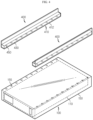
- FIG. 1 is a diagram illustrating a battery rack according to an embodiment of the present disclosure
- FIG. 2 is a front view of the battery rack of FIG. 1
- FIG. 3 is a side cross-sectional view of a battery pack of FIG. 1
- FIG. 4 is a diagram illustrating the coupling between a battery module and a support bracket of the battery rack of FIG. 1 .
- the battery rack 10 may include a battery module 100, a rack case 200 and a support bracket 400.
- a plurality of battery modules 100 may be included.
- the plurality of battery modules 100 may be stacked on top of each other along the vertical direction of the rack case 200 as described below.
- Each of the plurality of battery modules 100 may include a battery cell 110 and a module case 150.
- the battery cell 110 may be a secondary battery, for example, a pouch type secondary battery, a prismatic se4codnary battery or a cylindrical secondary battery.
- a pouch type secondary battery for example, a pouch type secondary battery, a prismatic se4codnary battery or a cylindrical secondary battery.
- this embodiment is described by taking the pouch type secondary battery as an example of the battery cell 110.
- One or more battery cells 110 may be included.
- the plurality of battery cells 110 may be stacked such that they are electrically connected to each other.
- the module case 150 may accommodate one or more battery cells 110. To this end, the module case 150 may have an accommodation space in which one or more battery cells 110 are received.
- the module case 150 may have a venting hole 155 through which vent gas G (see FIGS. 7 and 8 ) vented from the battery cell 110 is vented to the atmosphere in the event of an abnormal situation such as overheat of one or more battery cells 110.
- venting holes 155 may be included. Hereinafter, this embodiment is described based on the plurality of venting holes 155.
- the plurality of venting holes 155 may be disposed in the upper surface of the module case 150. Specifically, the plurality of venting holes 155 may be disposed at two edges of the upper surface of the module case 150 in the lengthwise direction of the module case 150.
- venting holes 155 at each of the two edges of the upper surface may be arranged spaced a predetermined distance apart along the lengthwise direction of the module case 150.
- the plurality of venting holes 155 may be disposed at locations corresponding to guide holes 450 of the support bracket 400 as described below. Specifically, in the assembly of the battery module 100 and the support bracket 400 as described below, the plurality of venting holes 155 may be in communication with the guide holes 450 of the support bracket 400 as described below.
- the rack case 200 may accommodate the plurality of battery modules 100. To this end, the rack case 200 may have a predetermined length along the vertical direction of the plurality of battery modules 100, i.e., the heightwise direction.
- a plurality of rack cases 200 may be included to support the plurality of battery modules 100 together with a base bracket 300 and the support bracket 400 as described below.
- the rack case 200 may include a venting channel 250 in communication with guide channels 430 of the plurality of support brackets 400 as described below.
- the venting channel 250 may be disposed on the inner surface of the rack case 200, and may be formed along the lengthwise direction of the rack case 200, i.e., the heightwise direction.
- the venting channel 250 may be integrally formed in the rack case 200.
- the venting channel 250 may be used to guide the route of the vent gas G (see FIGS. 7 and 8 ) to a predetermined location, and may guide the vent gas G to the predetermined location for preventing a fire or ignition caused by the vent gas G.
- the venting channel 250 may guide the vent gas G to a location for avoiding an ignition risk zone where the vent gas G is mixed with outdoor air and ignition is highly likely to occur, a location for delaying ignition to the maximum extent or a location for minimizing damage to a user in the event of ignition.
- venting channel 250 may be disposed in the rack case 200 at the rear of the battery modules 100.
- the venting channel 250 may guide the vent gas G from the battery modules 100 to the top rear side of the rack case 200.
- the exposed opening of the venting channel 250 may be connected to an additional instrument such as an ignition prevention device to prevent the ignition. That is, the venting channel 250 may be configured to guide the vent gas G to a preset route for preventing or delaying the ignition. To this end, the venting channel 250 may be in communication with the guide channels 430 of the plurality of support brackets 400 as described below.
- the venting channel 250 may have a plurality of channel holes 255.
- the plurality of channel holes 255 may be arranged spaced a predetermined distance apart along the lengthwise direction of the venting channel 250, i.e., the heightwise direction, and may be connected in communication with channel connection holes 435 of the guide channels 430 of the support brackets 400 as described below.
- the battery rack 10 may further include the base bracket 300.
- the base bracket 300 may be configured to support the battery modules 100 and reinforce the strength of the rack case 200, and may be coupled to the rack case 200.
- the base bracket 300 may be disposed on bottom of the bottommost battery module 100 among the plurality of battery modules 100 in the heightwise direction of the rack case 200.
- a plurality of support brackets 400 may be included.
- the plurality of support brackets 400 may be disposed between the plurality of battery modules 100 in the vertical direction of the rack case 200, i.e., the heightwise direction.
- the plurality of support brackets 400 may be arranged spaced a predetermined distance apart in the heightwise direction of the rack case 200 to increase the cooling performance of the plurality of battery modules 100.
- the plurality of support brackets 400 may be disposed in the rack case 200 such that each support bracket 400 supports each battery module 100, and may be in communication with the at least one venting hole 155.
- the plurality of support brackets 400 may be also in communication with the venting channel 250 of the rack case 200 to guide the vent gas G (see FIGS. 7 and 8 ) coming from the at least one venting hole 155 to the venting channel 250 of the rack case 200.
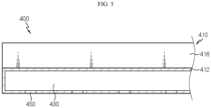
- FIG. 5 is a diagram illustrating the support bracket of the battery rack of FIG. 1 .
- each of the plurality of support brackets 400 may include a bracket body 410, the guide channel 430 and the guide hole 450.
- the bracket body 410 may form the exterior of the support bracket 400, and may include a main body 412 and an auxiliary body 416.
- the main body 412 may be disposed between the battery modules 100 in the vertical direction of the rack case 200, i.e., the heightwise direction.
- the main body 412 may support the top and bottom of the battery modules 100.
- the guide channel 430 as described below may be disposed in the main body 412. Furthermore, one or more guide holes 450 in communication with the guide channel 430 as described below may be disposed on bottom of the main body 412.
- the auxiliary body 416 may be extended from the main body 412, and may be disposed between the battery module 100 and the rack case 200.
- the auxiliary body 416 may support two sides of the battery module 100.
- the guide channel 430 may be disposed in the main body 412, and may have a predetermined length along the lengthwise direction of the main body 412.
- the guide channel 430 may guide the flow route of the vent gas G (see FIGS. 7 and 8 ) vented from one or more venting holes 155.
- the channel connection holes 435 for communication with the channel holes 255 of the venting channel 250 may be disposed at the end of the guide channel 430.
- the guide hole 450 may be disposed on bottom of the guide channel 430, and may be in communication with the at least one venting hole 155.
- One or more guide holes 450 may be included.
- the number of guide holes 450 may correspond to the number of venting holes 155.
- one or more guide holes 450 may be disposed at a location corresponding to the at least one venting hole 450.
- FIG. 6 is a diagram illustrating a support bracket according to another embodiment of the battery rack of FIG. 1 .
- the support bracket 405 according to this embodiment is similar to the support bracket 400 of the previous embodiment, and overlapping descriptions of some components that are substantially identical or similar to the previous embodiment are omitted and the following description is made based on difference(s) between this embodiment and the previous embodiment.
- the support bracket 405 may include a bracket body 410, a guide channel 430, a guide hole 450 and a barrier membrane 470.
- the bracket body 410, the guide channel 430 and the guide hole 450 are substantially identical or similar to the previous embodiment, and overlapping descriptions are omitted.
- the barrier membrane 470 may be disposed in the one or more guide holes 450, and may open or close the one or more guide holes 450 according to a predetermined temperature.
- the barrier membrane 470 may melt or tear at the predetermined temperature or above to make the one or more guide holes 450 and the one or more venting holes 155 communicate with each other.
- the barrier membrane 470 may be a plastic membrane having a predetermined thickness that melts at the predetermined temperature or above.
- the barrier membrane 470 melts to make the venting hole 155 and the guide hole 450 communicate with each other so as to guide the flow of the vent gas.
- the barrier membrane 470 may prevent moisture or impurities from entering the venting hole 155 through the guide hole 450.
- the barrier membrane 470 may prevent high temperature outdoor air that may enter through the guide hole 450 from entering the venting hole 155, thereby ensuring the cooling performance of the battery module 100 in the normal situation.
- the barrier membrane 470 may close the guide hole 450, thereby effectively preventing damage of the battery module 100 or the cooling performance degradation of the battery module 100 due to the moisture or impurities, and in the abnormal situation of the battery module 100, the barrier membrane 470 may be opened to make the guide hole 450 and the venting hole 155 communicate with each other, thereby effectively guiding the vent gas to the guide channel 430.
- FIGS. 7 and 8 are diagrams illustrating the mechanism for preventing flaring or ignition by rerouting the vent gas generated from the battery module of the battery rack of FIG. 1 .
- At least one battery module 100 of the battery rack 10 may be overheated due to the abnormal situation.
- the abnormal situation may lead to a dangerous situation such as thermal runaway of the battery module 100.
- the vent gas G from the overheated battery cell 110 in the battery module 100 may be vented through the venting hole 155.
- vent gas G is vented toward the front and rear sides of the battery module 100, and when the vent gas G is immediately mixed with outdoor air and enters an ignition risk zone, unintentional flames occurs, causing a bigger danger.
- the vent gas G may enter the guide channel 430 through the guide hole 450 of the support bracket 400 in communication with the battery module 100, and subsequently, the vent gas G may be guided to the venting channel 250 of the rack case 200 along the guide channel 430.
- the vent gas G may exit the rack case 200 through the venting channel 250 of the rack case 200, or may be guided by the additional instrument such as the ignition prevention device connected to the venting channel 250 of the rack case 200.
- the vent gas G may be guided to a location away from the battery modules 100 through the guide channel 430 of the support bracket 400 and the venting channel 250 of the rack case 200, thereby significantly reducing the likelihood that unintentional flames occur compared to the case in which the vent gas G is directly vented toward the front and rear sides of the battery module 100.
- FIG. 9 is a diagram illustrating an energy storage system according to an embodiment of the present disclosure.
- the energy storage system 1 may be used in the domestic or industrial applications as an energy source.
- the energy storage system 1 may include at least one battery rack 10 and a rack container 50 accommodating the at least one battery rack 10.
- the energy storage system 1 may include all the advantages of the battery rack 10 of the previous embodiment.
- the battery rack 10 for preventing flaring or ignition caused by the vent gas G vented from the battery module 100 in the abnormal situation and the energy storage system 1 including the same.
Landscapes
- Chemical & Material Sciences (AREA)
- Chemical Kinetics & Catalysis (AREA)
- Electrochemistry (AREA)
- General Chemical & Material Sciences (AREA)
- Battery Mounting, Suspending (AREA)
- Gas Exhaust Devices For Batteries (AREA)
Applications Claiming Priority (2)
| Application Number | Priority Date | Filing Date | Title |
|---|---|---|---|
| KR1020210098142A KR20230016531A (ko) | 2021-07-26 | 2021-07-26 | 배터리 랙 및 이를 포함하는 에너지 저장 장치 |
| PCT/KR2022/010988 WO2023008886A1 (ko) | 2021-07-26 | 2022-07-26 | 배터리 랙 및 이를 포함하는 에너지 저장 장치 |
Publications (2)
| Publication Number | Publication Date |
|---|---|
| EP4290664A1 true EP4290664A1 (de) | 2023-12-13 |
| EP4290664A4 EP4290664A4 (de) | 2024-11-06 |
Family
ID=85087150
Family Applications (1)
| Application Number | Title | Priority Date | Filing Date |
|---|---|---|---|
| EP22849862.2A Pending EP4290664A4 (de) | 2021-07-26 | 2022-07-26 | Batteriegestell und energiespeichersystem damit |
Country Status (6)
| Country | Link |
|---|---|
| US (1) | US20240088516A1 (de) |
| EP (1) | EP4290664A4 (de) |
| JP (1) | JP7671852B2 (de) |
| KR (1) | KR20230016531A (de) |
| CN (1) | CN116918156A (de) |
| WO (1) | WO2023008886A1 (de) |
Cited By (1)
| Publication number | Priority date | Publication date | Assignee | Title |
|---|---|---|---|---|
| EP4564558A1 (de) * | 2023-11-28 | 2025-06-04 | Samsung Sdi Co., Ltd. | Energiespeichersystem |
Families Citing this family (4)
| Publication number | Priority date | Publication date | Assignee | Title |
|---|---|---|---|---|
| KR20240154955A (ko) * | 2023-04-19 | 2024-10-28 | 에스케이온 주식회사 | 배터리 랙 및 에너지 저장 시스템 |
| JP7794183B2 (ja) * | 2023-09-01 | 2026-01-06 | トヨタ自動車株式会社 | 電池パック |
| CN223039069U (zh) * | 2024-04-08 | 2025-06-27 | 宁德时代新能源科技股份有限公司 | 电池及储能装置 |
| DE202025101733U1 (de) * | 2024-06-07 | 2025-05-13 | Eve Energy Co., Ltd. | Batteriepack und elektrischer Verbraucher |
Family Cites Families (11)
| Publication number | Priority date | Publication date | Assignee | Title |
|---|---|---|---|---|
| MXPA03002624A (es) * | 2000-09-27 | 2004-05-24 | Exide Technologies | Sistema de bastidor de acumulador valorado sismicamente. |
| US7740142B2 (en) * | 2001-11-20 | 2010-06-22 | Concorde Battery Corporation | Battery construction for mounting a shelved rack |
| JP5749200B2 (ja) * | 2011-03-30 | 2015-07-15 | テスラ・モーターズ・インコーポレーテッド | バッテリパックガス排出システム |
| KR101264338B1 (ko) * | 2011-07-14 | 2013-05-14 | 삼성에스디아이 주식회사 | 랙 하우징 조립체 및 이를 구비한 전력저장장치 |
| JP5914828B2 (ja) * | 2011-07-29 | 2016-05-11 | パナソニックIpマネジメント株式会社 | 電池パック |
| WO2015045401A1 (ja) * | 2013-09-30 | 2015-04-02 | パナソニックIpマネジメント株式会社 | 電池固定用フレーム部材、電池固定部材及び蓄電装置 |
| SG11201809267PA (en) * | 2016-04-20 | 2018-11-29 | Corvus Energy Inc | Method and apparatus for managing thermal runaway gases in a battery system |
| KR20180006150A (ko) * | 2016-07-08 | 2018-01-17 | 주식회사 엘지화학 | 안전성이 개선된 셀 모듈 어셈블리 및 이를 위한 팩 구조물 |
| CN112531246B (zh) * | 2019-08-31 | 2022-06-14 | 比亚迪股份有限公司 | 电池托盘、动力电池包及车辆 |
| WO2021091328A1 (ko) * | 2019-11-08 | 2021-05-14 | 주식회사 엘지화학 | 배터리 랙 및 이를 포함하는 전력 저장 장치 |
| KR102299900B1 (ko) | 2020-01-31 | 2021-09-09 | 대구대학교 산학협력단 | 실시간 채팅 장치 |
-
2021
- 2021-07-26 KR KR1020210098142A patent/KR20230016531A/ko not_active Ceased
-
2022
- 2022-07-26 CN CN202280017665.6A patent/CN116918156A/zh active Pending
- 2022-07-26 JP JP2023544143A patent/JP7671852B2/ja active Active
- 2022-07-26 US US18/274,922 patent/US20240088516A1/en active Pending
- 2022-07-26 WO PCT/KR2022/010988 patent/WO2023008886A1/ko not_active Ceased
- 2022-07-26 EP EP22849862.2A patent/EP4290664A4/de active Pending
Cited By (1)
| Publication number | Priority date | Publication date | Assignee | Title |
|---|---|---|---|---|
| EP4564558A1 (de) * | 2023-11-28 | 2025-06-04 | Samsung Sdi Co., Ltd. | Energiespeichersystem |
Also Published As
| Publication number | Publication date |
|---|---|
| CN116918156A (zh) | 2023-10-20 |
| KR20230016531A (ko) | 2023-02-02 |
| US20240088516A1 (en) | 2024-03-14 |
| WO2023008886A1 (ko) | 2023-02-02 |
| JP7671852B2 (ja) | 2025-05-02 |
| EP4290664A4 (de) | 2024-11-06 |
| JP2024505840A (ja) | 2024-02-08 |
Similar Documents
| Publication | Publication Date | Title |
|---|---|---|
| EP4290664A1 (de) | Batteriegestell und energiespeichersystem damit | |
| EP3644403B1 (de) | Batteriemodul mit gasentladungsstruktur | |
| EP4156382A1 (de) | Batteriemodul sowie batteriepack und fahrzeug damit | |
| EP4664644A1 (de) | Batteriepack und fahrzeug damit | |
| EP4191750B1 (de) | Batteriepack mit verbesserter kühlleistung sowie vorrichtung damit | |
| EP4250437A1 (de) | Batteriemodul und batteriepack damit | |
| EP4096008B1 (de) | Batteriepack und vorrichtung damit | |
| EP4318773A1 (de) | Batteriepack, energiespeichersystem und fahrzeug mit batteriepack | |
| US20230128563A1 (en) | Battery module having pocket capable of capturing flare and spark ejected during swelling | |
| EP4354597A1 (de) | Batteriepack und energiespeichersystem sowie fahrzeug mit dem batteriepack | |
| KR20130113145A (ko) | 안전성이 향상된 단위모듈 어셈블리 및 이를 포함하는 전지모듈 | |
| KR20230016532A (ko) | 배터리 모듈, 이를 포함하는 배터리 팩 및 자동차 | |
| EP4465431A1 (de) | Batteriemodul sowie batteriepack und fahrzeug damit | |
| KR20230160464A (ko) | 열폭주 전파를 방지하는 배터리 모듈 | |
| EP4325633A1 (de) | Batteriemodul, batteriepack mit solch einem batteriemodul sowie energiespeichervorrichtung und fahrzeug mit solch einem batteriepack | |
| EP4167367B1 (de) | Batteriemodul mit gebogenem fallenteil und batteriepack damit | |
| EP4411960A1 (de) | Batteriemodul und batteriepack sowie fahrzeug damit | |
| EP4685965A1 (de) | Batteriepack und ess damit | |
| EP4648200A1 (de) | Batteriezelle und fahrzeug damit | |
| EP4645562A1 (de) | Batteriemodul, batteriepack und fahrzeug damit | |
| EP4386960A1 (de) | Batteriepack und fahrzeug damit | |
| EP4475314A1 (de) | Batteriepack und fahrzeug damit | |
| TW202516777A (zh) | 電池組以及包括電池組之載具 | |
| KR20260005630A (ko) | 배터리 모듈 및 배터리 팩 및 자동차 | |
| JP2025530761A (ja) | バッテリーパック及びそれを含む自動車 |
Legal Events
| Date | Code | Title | Description |
|---|---|---|---|
| STAA | Information on the status of an ep patent application or granted ep patent |
Free format text: STATUS: THE INTERNATIONAL PUBLICATION HAS BEEN MADE |
|
| PUAI | Public reference made under article 153(3) epc to a published international application that has entered the european phase |
Free format text: ORIGINAL CODE: 0009012 |
|
| STAA | Information on the status of an ep patent application or granted ep patent |
Free format text: STATUS: REQUEST FOR EXAMINATION WAS MADE |
|
| 17P | Request for examination filed |
Effective date: 20230908 |
|
| AK | Designated contracting states |
Kind code of ref document: A1 Designated state(s): AL AT BE BG CH CY CZ DE DK EE ES FI FR GB GR HR HU IE IS IT LI LT LU LV MC MK MT NL NO PL PT RO RS SE SI SK SM TR |
|
| DAV | Request for validation of the european patent (deleted) | ||
| DAX | Request for extension of the european patent (deleted) | ||
| A4 | Supplementary search report drawn up and despatched |
Effective date: 20241007 |
|
| RIC1 | Information provided on ipc code assigned before grant |
Ipc: H01M 50/251 20210101ALI20241001BHEP Ipc: H01M 50/375 20210101ALI20241001BHEP Ipc: H01M 50/358 20210101AFI20241001BHEP |
|
| STAA | Information on the status of an ep patent application or granted ep patent |
Free format text: STATUS: EXAMINATION IS IN PROGRESS |
|
| 17Q | First examination report despatched |
Effective date: 20250509 |
|
| GRAP | Despatch of communication of intention to grant a patent |
Free format text: ORIGINAL CODE: EPIDOSNIGR1 |
|
| STAA | Information on the status of an ep patent application or granted ep patent |
Free format text: STATUS: GRANT OF PATENT IS INTENDED |
|
| INTG | Intention to grant announced |
Effective date: 20250918 |
|
| P01 | Opt-out of the competence of the unified patent court (upc) registered |
Free format text: CASE NUMBER: UPC_APP_8738_4290664/2025 Effective date: 20251002 |
|
| GRAS | Grant fee paid |
Free format text: ORIGINAL CODE: EPIDOSNIGR3 |
|
| GRAA | (expected) grant |
Free format text: ORIGINAL CODE: 0009210 |
|
| STAA | Information on the status of an ep patent application or granted ep patent |
Free format text: STATUS: THE PATENT HAS BEEN GRANTED |