EP4290480B1 - Detektion der reflexion von objekten in einer sequenz von bildrahmen - Google Patents
Detektion der reflexion von objekten in einer sequenz von bildrahmen Download PDFInfo
- Publication number
- EP4290480B1 EP4290480B1 EP22177455.7A EP22177455A EP4290480B1 EP 4290480 B1 EP4290480 B1 EP 4290480B1 EP 22177455 A EP22177455 A EP 22177455A EP 4290480 B1 EP4290480 B1 EP 4290480B1
- Authority
- EP
- European Patent Office
- Prior art keywords
- detected
- objects
- normalized
- detected object
- reflection
- Prior art date
- Legal status (The legal status is an assumption and is not a legal conclusion. Google has not performed a legal analysis and makes no representation as to the accuracy of the status listed.)
- Active
Links
Images


Classifications
-
- G—PHYSICS
- G06—COMPUTING OR CALCULATING; COUNTING
- G06V—IMAGE OR VIDEO RECOGNITION OR UNDERSTANDING
- G06V20/00—Scenes; Scene-specific elements
- G06V20/50—Context or environment of the image
-
- G—PHYSICS
- G06—COMPUTING OR CALCULATING; COUNTING
- G06V—IMAGE OR VIDEO RECOGNITION OR UNDERSTANDING
- G06V20/00—Scenes; Scene-specific elements
- G06V20/40—Scenes; Scene-specific elements in video content
- G06V20/41—Higher-level, semantic clustering, classification or understanding of video scenes, e.g. detection, labelling or Markovian modelling of sport events or news items
-
- G—PHYSICS
- G06—COMPUTING OR CALCULATING; COUNTING
- G06T—IMAGE DATA PROCESSING OR GENERATION, IN GENERAL
- G06T7/00—Image analysis
- G06T7/20—Analysis of motion
- G06T7/246—Analysis of motion using feature-based methods, e.g. the tracking of corners or segments
- G06T7/248—Analysis of motion using feature-based methods, e.g. the tracking of corners or segments involving reference images or patches
-
- G—PHYSICS
- G06—COMPUTING OR CALCULATING; COUNTING
- G06T—IMAGE DATA PROCESSING OR GENERATION, IN GENERAL
- G06T7/00—Image analysis
- G06T7/70—Determining position or orientation of objects or cameras
- G06T7/73—Determining position or orientation of objects or cameras using feature-based methods
- G06T7/74—Determining position or orientation of objects or cameras using feature-based methods involving reference images or patches
-
- G—PHYSICS
- G06—COMPUTING OR CALCULATING; COUNTING
- G06V—IMAGE OR VIDEO RECOGNITION OR UNDERSTANDING
- G06V10/00—Arrangements for image or video recognition or understanding
- G06V10/40—Extraction of image or video features
- G06V10/60—Extraction of image or video features relating to illumination properties, e.g. using a reflectance or lighting model
-
- G—PHYSICS
- G06—COMPUTING OR CALCULATING; COUNTING
- G06V—IMAGE OR VIDEO RECOGNITION OR UNDERSTANDING
- G06V20/00—Scenes; Scene-specific elements
- G06V20/40—Scenes; Scene-specific elements in video content
- G06V20/46—Extracting features or characteristics from the video content, e.g. video fingerprints, representative shots or key frames
-
- G—PHYSICS
- G06—COMPUTING OR CALCULATING; COUNTING
- G06V—IMAGE OR VIDEO RECOGNITION OR UNDERSTANDING
- G06V20/00—Scenes; Scene-specific elements
- G06V20/50—Context or environment of the image
- G06V20/52—Surveillance or monitoring of activities, e.g. for recognising suspicious objects
-
- G—PHYSICS
- G06—COMPUTING OR CALCULATING; COUNTING
- G06V—IMAGE OR VIDEO RECOGNITION OR UNDERSTANDING
- G06V40/00—Recognition of biometric, human-related or animal-related patterns in image or video data
- G06V40/10—Human or animal bodies, e.g. vehicle occupants or pedestrians; Body parts, e.g. hands
- G06V40/103—Static body considered as a whole, e.g. static pedestrian or occupant recognition
-
- G—PHYSICS
- G06—COMPUTING OR CALCULATING; COUNTING
- G06T—IMAGE DATA PROCESSING OR GENERATION, IN GENERAL
- G06T2207/00—Indexing scheme for image analysis or image enhancement
- G06T2207/10—Image acquisition modality
- G06T2207/10016—Video; Image sequence
-
- G—PHYSICS
- G06—COMPUTING OR CALCULATING; COUNTING
- G06T—IMAGE DATA PROCESSING OR GENERATION, IN GENERAL
- G06T2207/00—Indexing scheme for image analysis or image enhancement
- G06T2207/30—Subject of image; Context of image processing
- G06T2207/30204—Marker
-
- G—PHYSICS
- G06—COMPUTING OR CALCULATING; COUNTING
- G06T—IMAGE DATA PROCESSING OR GENERATION, IN GENERAL
- G06T2207/00—Indexing scheme for image analysis or image enhancement
- G06T2207/30—Subject of image; Context of image processing
- G06T2207/30232—Surveillance
Definitions
- Embodiments presented herein relate to a method, a controller, a computer program, and a computer program product for detecting a reflection of an object in a sequence of image frames.
- object detection is a computer technology related to computer vision and image processing that deals with detecting instances of semantic objects of a certain class (such as human beings, animals, vehicles, etc.).
- Some object detection algorithms produce key points, or other types of object position indicators. Such points, or indicators, generally represent points of interest for the target object as tracked from one image frame to the next.
- US 2020/0175694 A1 is disclosed an information processing device that includes a specification circuit and a count circuit.
- the specification circuit specifies, based on a similarity of speed depending on a change in positions of a plurality of movable objects in an image, two or more movable objects corresponding to a same real movable object in the movable objects.
- the count circuit counts the number of real movable objects corresponding to the movable objects based on the specification result of the specification circuit.
- US 2015/363654 A1 and US 2016/019698 A1 further background information can be found.
- a reflection is not perfectly equal to the tracked object it is reflecting.
- a reflection might appear smaller or larger than the tracked object.
- reflections made in semitransparent surfaces make the reflection have less details in the image frames than the tracked object.
- the reflection might only include parts of the tracked object. This could cause the specification circuit in the information processing device in US 2020/0175694 A1 to make erroneous decisions as to whether two or more movable objects correspond to the same real movable object in the movable objects.
- An object of embodiments herein is to address the above issues and to provide improved detection of objects in reflective surfaces.
- a controller for detecting a reflection of an object in a sequence of image frames.
- the controller is defined in the appended set of claims.
- the video surveillance system comprises a controller according the second aspect and a camera for capturing the sequence of image frames.
- a computer program for detecting a reflection of an object in a sequence of image frames comprising computer program code which, when run on a controller, causes the controller to perform a method according to the first aspect.
- a computer program product comprising a computer program according to the fourth aspect and a computer readable storage medium on which the computer program is stored.
- the computer readable storage medium could be a non-transitory computer readable storage medium.
- these aspects provide computationally efficient and accurate detection of objects in scenarios, or environments, having reflective surfaces.
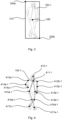
- Fig. 1 is a schematic diagram illustrating a video surveillance system 100 where embodiments presented herein can be applied.
- a camera 120 is configured to capture image frames, within a Field-of-View (FoV) 130, of a scene 140.
- the scene 140 comprises an object 150-1 in the form of a human being.
- the camera 120 comprises, is collocated with, is integrated with, or at least operatively connected to, a controller 110.
- the object 150-1 represents a target object that is to be tracked from image frame to image frame, as captured by the camera 120 and as analyzed by the controller 110.
- the controller 110 might implement an object detection algorithm.
- the embodiments disclosed herein relate to techniques for detecting a reflection of an object 150-1 in a sequence of image frames.
- a controller 110 a method performed by the controller 110, a computer program product comprising code, for example in the form of a computer program, that when run on a controller 110, causes the controller 110 to perform the method.
- Fig. 2 schematically illustrates an image frame 200.
- the image frame 200 depicts an object 150-1 in the form of a human being, as in the scene 140.
- the object 150-1 has a location marked at reference numeral 220-1 in the image frame 200.
- In the image frame 200 is further depicted a reflection surface 210.
- the reflection surface 210 has a location marked at reference numeral 230 in the image frame 200.
- the reflection surface 210 causes also a further object 150-2 to be visible.
- Object 150-2 is a reflection of object 150-1, as caused by object 150-1 being reflected by the reflection surface 210.
- the object 150-2 has a location marked at reference numeral 220-2 in the image frame 200.
- FIG. 3 and Fig. 4 schematically illustrate an object 150-1 in the form of a human being, as in the scene 140.
- Fig. 3 and Fig. 4 are shown different types of object position indicators.
- the bounding box 310 is defined by two corner points 320a, 320b and one center point 330.
- the center point 330 could represent the location 220-1 of the object 150-1.
- the corner points 320a, 320b and the center point 330 could, for instance, be CenterNet keypoints.
- the bounding box could, for instance, be a CenterNet bounding box.
- the object position indicators might be defined by two or more bounding boxes. That is, two or more bounding boxes might be used to enclose the detected object 150-1. That is, a first bounding box might enclose a first part (such as the head) of the detected object 150-1, a second bounding box might enclose a second part (such as the torso) of the detected object 150-1, and so on.
- a first bounding box might enclose a first part (such as the head) of the detected object 150-1
- a second bounding box might enclose a second part (such as the torso) of the detected object 150-1, and so on.
- the object 150-1 is overlayed by object position indicators 410-1 to 417b-1 as listed in Table 1.
- object position indicators could be regarded as a simplified version of COCO key points or MediaPipe Pose key points.
- Table 1 Correspondence between reference numbers and part of object Reference number 410-1 4111-1 412a-1, 412b-1 413a-1, 413b-1 414a-1, 414b-1 415a-1, 415b-1 416a-1, 416b-1 417a-1, 417b-1 Part of object Head Throat Shoulder (right and left) Elbow (right and left) Hand (right and left) Hip (right and left) Knee (right and left) Foot (right and left)
- the object 150-2 being the reflection will have an identical setup of object position indicators but reflected.
- object position indicators By analyzing the object position indicators, it is possible to determine object-reflection-pairs, at object level i.e., one tracked object 150-1 and its reflected counterpart object 150-2 or even at object position indicator level.
- Reference is here made to Fig. 5 which schematically illustrates object position indicators 410-1 to 417b-1 as listed in Table 1 of the object 150-1 (not shown). Fig. 5 also indicates the position 220-1 of the object 150-1.
- Fig. 5 further illustrates object position indicators 410-2 to 417b-2 of the object 150-2 (not shown) being a reflection of the object 150-1 in the reflection surface 210 at location 230.
- the object position indicators 410-2 to 417b-2 correspond to the object position indicators listed in Table 1. That is, object position indicator 410-2 represents the head of the object 150-2, and object position indicator 417b-2 represents the left foot of the object 150-2.
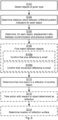
- Fig. 6 is a flowchart illustrating embodiments of methods for detecting a reflection of an object 150-1 in a sequence of image frames 200, 800, 900.
- the methods are performed by the controller 110.
- the methods are advantageously provided as computer programs 1120.
- the controller 110 detects objects 150-1, 150-2 of a given type in the sequence of image frames 200, 800, 900.
- the controller 110 determines a detection score for each detected object 150-1, 150-2.
- a detection score is also determined for each object position indicator identified for the detected object 150-1, 150-2 in addition to the detection score that is determined for each detected object 150-1, 150-2 as a whole.
- the detection scores of the individual object position indicators might only become relevant once the detection score of the detected object 150-1, 150-2 is above some threshold value.
- the detection score for a given detected object 150-1, 150-2 is a function of the detection scores for all unfiltered object position indicators identified for the given detected object 150-1, 150-2.
- the controller 110 determines, per each detected object 150-1, 150-2, distance ratios between unfiltered object position indicators identified for the detected object 150-1, 150-2.
- the unfiltered object position indicators are identified in a current image frame 200, 800, 900 in the sequence of image frames 200, 800, 900.
- the distance ratios for the detected object 150-1, 150-2 define a normalized size of the detected object 150-1, 150-2.
- the size of the detected object is determined per the detected object as a whole, the size is considered to be the normalized size of the detected object.
- the controller 110 determines, per each detected object 150-1, 150-2, a displacement factor between a current location 220-1, 220-2 of the detected object 150-1, 150-2 in the current image frame 200, 800, 900 and a previous location of the detected object 150-1, 150-2 in a previous image frame in the sequence of image frames 200, 800, 900.
- the displacement factor for the detected object 150-1, 150-2 defines a normalized movement for the detected object 150-1, 150-2.
- historical data in terms of a previous image frame in the sequence of image frames 200, 800, 900, is used for the controller 110 to obtain information of the location of the detected object in the previous image frame. Based on how much the detected object has moved from the previous image frame to the current image frame, a measure of the movement of the detected object can be obtained. Since the movement for the detected object is determined per the detected object as a whole, the movement is considered to be the normalized movement for the detected object.
- the normalized sizes and the normalized movements of two of the detected objects 150-1, 150-2 can then be compared to each other. That is, the normalized size of one of the two detected objects 150-1, 150-2 is compared to the normalized size of the other of the two detected objects 150-1, 150-2 and the normalized movement of one of the two detected objects 150-1, 150-2 is compared to the normalized movement of the other of the two detected objects 150-1, 150-2.
- the normalized sizes and the normalized movements imply that certain given measures (the size for the normalized sizes and the movement for the normalized movements) are scaled, or otherwise recalculated, to a common scale.
- the effect will be that the object 150-1 and the reflection of the object will appear to be of mutually different sizes; the one being located closest to the camera will appear to be larger, and vice versa.
- the object 150-1 and the reflection of the object will be scaled, or otherwise recalculated, to a common size scale where this effect will be accounted for such that the object 150-1 and the reflection of the object will appear to be of one and the same size.
- the effect will also be that the object 150-1 and the reflection of the object will appear to move at mutually different speeds; the one being located closest to the camera will appear to move faster, and vice versa.
- the object 150-1 and the reflection of the object will be scaled, or otherwise recalculated, to a common movement scale where this effect will be accounted for such that the object 150-1 and the reflection of the object will appear to move at one and the same speed.
- the controller 110 determines, in response to finding a match between the normalized sizes and the normalized movements of two of the detected objects 150-1, 150-2, that the one of these two detected objects 150-1, 150-2 which has a lower detection score is a reflection of the other of these two detected objects 150-1, 150-2.
- the detected object 150-2 with a comparatively low detection score is classified as a reflection of the detected object 150-1 with a comparatively high detection score.
- Embodiments relating to further details of detecting a reflection of an object 150-1 in a sequence of image frames 200, 800, 900 as performed by the controller 110 will now be disclosed.
- the controller 110 detects objects 150-1, 150-2 of a given type in the sequence of image frames 200, 800, 900.
- the given type is a human being, an animal, or a vehicle, such as a car or a truck.
- the controller 110 could therefore have been trained, and thereby configured, to detect objects 150-1, 150-2 of the given type.
- the controller 110 determines, per each detected object 150-1, 150-2, distance ratios between unfiltered object position indicators identified for the detected object 150-1, 150-2.
- the unfiltered object position indicators are object position indicators that have been determined without any objects that have been detected with low detection scores first having been filtered out. That is, unfiltered object position indicators refers to the object position indicators before thresholding is performed to mitigate the false positives in the scene. Since reflections generally have a lower detection score than their non-reflected counterpart, unfiltered object position indicators are used so that the detected object 150-2 being the reflection is not missed. That is, some of the unfiltered object position indicators might belong to objects that would otherwise be filtered out, or discarded, due to producing a low detection score.
- the unfiltered object position indicators are determined for all detected objects 150-1, 150-2 without any of the detected objects 150-1, 150-2 having been filtered out (due to their detection score being lower than a detection threshold). Further in this respect, there could be different types of object position indicators.
- each of the object position indicators is a Common Objects in Context, COCO, key point 410-1:417b-1, 410-2:417b-2, or a MediaPipe Pose key point.
- the object position indicators need not to be defined by all COCO key points or MediaPipe Pose key points, but rather a subset of these key points could be used as object position indicators. This is illustrated in Fig. 4 as referred to above.
- the object position indicators are corner points 320s, 320b and center points 330 of bounding boxes 310, such as CenterNet bounding boxes. This is illustrated in Fig. 3 as referred to above.
- the controller 110 is configured to perform (optional) step S108.
- the controller 110 finds the match between the normalized sizes and/or the normalized movements of two of the detected objects 150-1, 150-2.
- controller 110 finds the match between the normalized sizes and/or the normalized movements of two of the detected objects 150-1, 150-2.
- this match-finding is performed by comparing the normalized size and/or the normalized movement of a first detected object 150-1 to the normalized size and/or the normalized movement of a second detected object 150-2.
- the controller 110 is configured to perform (optional) step S108a and/or step S108b as part of step S108.
- the controller 110 confirms that a size difference between the normalized size of one of the two detected objects 150-1, 150-2 and the normalized size of the other of the two detected objects 150-1, 150-2 is smaller than a size threshold.
- S108b The controller 110 confirms that a movement difference between the normalized movement of one of the two detected objects 150-1, 150-2 and the normalized movement of the other of the two detected objects 150-1, 150-2 is smaller than a movement threshold.
- the matching is performed on an object position indicator level. That is, instead of just comparing the normalized size and/or the normalized movement of a first detected object 150-1 to the normalized size and/or the normalized movement of a second detected object 150-2, a comparison (with respect to size and/or movement) is made between pairs of object position indicators in one of the two detected objects 150-1, 150-2 and pairs of object position indicators in the other of the two detected objects 150-1, 150-2.
- the two detected objects 150-1, 150-2 represent a human being and the knees of both legs are detectable and are represented by object position indicators in both the two detected objects 150-1, 150-2. Then a first comparison can be made between the normalized distance between the knees according to the object position indicators in one of the two detected objects 150-1, 150-2 and the normalized distance between the knees according to the object position indicators in the other of the two detected objects 150-1, 150-2. Further, a second comparison can be made between the normalized movement of the knees, as given by the object position indicators, in one of the two detected objects 150-1, 150-2 and the normalized movement of the knees, as given by the object position indicators, of the other of the two detected objects 150-1, 150-2. Further such comparisons with respect to size and/or movement can be made for further parts of the detected objects to accumulate a matching score for the two detected objects 150-1, 150-2.
- the controller 110 performs some action upon determination that one of the two detected objects 150-1, 150-2 is a reflection of the other of the two detected objects 150-1, 150-2. Hence, in some embodiments, the controller 110 is configured to perform (optional) step S112.
- S112 The controller 110 performs an action with respect to the detected object 150-2 being the reflection of the other detected object 150-1.
- the action involves applying a mask 810-2 to the detected object 150-2 being the reflection of the other detected object 150-1.
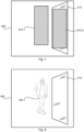
- Fig. 7 schematically illustrates an image frame 800.
- the image frame 800 depicts how a first mask 810-1 has been placed where object 150-1 appeared in Fig. 2 and a second mask 810-2 has been placed where object 150-2 appeared in Fig. 2 .
- the action involves filtering out the detected object 150-2 being the reflection of the other detected object 150-1, lowering the detection score threshold for the detected object 150-2 being the reflection of the other detected object 150-1, etc.
- Fig. 7 schematically illustrates an image frame 800.
- the image frame 800 depicts how a first mask 810-1 has been placed where object 150-1 appeared in Fig. 2 and a second mask 810-2 has been placed where object 150-2 appeared in Fig. 2 .
- the action involves filtering out the detected object 150-2 being the reflection of the other detected object 150-1, lowering the detection score threshold for the detected object 150-2 being the reflection of the other detected object
- FIG. 8 which schematically illustrates an image frame 900.
- the image frame 900 depicts an object 150-1 as in Fig. 2 , but where object 150-2 has been filtered out to not appear in image frame 900.
- object 150-2 representing the reflection is illustrated as being filtered out from the image frame, it is noted that the filtering out generally refers to filtering out the detected object 150-2 from some counting, or other type of calculation, such that object 150-1 is not counted twice.
- the reflection is caused by a reflection surface 210 being placed between the two detected objects 150-1, 150-2.
- the reflection surface 210 is placed at a midpoint between the locations 220-1, 220-2 of the two detected objects 150-1, 150-2. Therefore, knowledge of the locations 220-1, 220-2 of the two detected objects 150-1, 150-2 is used to determine the location 230 of the reflection surface 210.
- the controller 110 is configured to perform (optional) step S114.
- the controller 110 determines a location 230 of a reflection surface 210 causing the one of the detected objects 150-1, 150-2 to be the reflection of the other detected object 150-1, 150-2.
- the location 230 of the reflection surface 210 is determined as a midpoint between the locations 220-1, 220-2 of the two detected objects 150-1, 150-2.
- knowledge of the location 230 of the reflection surface 210 is utilized for detection of further objects in the sequence of image frames 200, 800, 900. Since the location 230 of the reflection surface 210 can be used as a reference point, or reference line, or even reference surface, knowledge of the location 230 could improve the chance of detecting reflected objects in challenging lighting conditions in future image frames of the same scene, or at least scenes where the reflection surface 210 is still present in the scene.
- the matching referring to the normalized sizes of the objects 150-1, 150-2 no consideration needs to be made with respect to that the object position indicators 410-2 to 417b-2 of the object 150-2 are mirrored compared to the object position indicators 410-1 to 417b-1 of the object 150-1.
- the matching referring to the normalized movements of the objects 150-1, 150-2 the normalized movement for object 150-1 will be the same as the normalized movements for object 150-2 except for a possible change of sign, due to the placement of the reflection surface 210 with respect to the detected objects 150-1, 150-2. For example, with the placement of the reflection surface 210 as in Fig. 2 , if object 150-1 appears to move towards the left in Fig.
- object 150-2 appears to move towards the right in Fig. 2 .
- the normalized movement might be represented by only its magnitude, without considering its direction.
- the reflection should be taken into considerations when the matching involves any object position indicators for which there is both a right object position indicator and a left object position indicator per each object, such as object position indicators 412a-1, 412b-1, etc.
- the thus far disclosed methods and controller 110 might be used as part of techniques for improving detection of human beings and other objects 150-1 in scenes 140 with glass surfaces.
- Glass surfaces may be both reflective and transmissive.
- a reflected image may be dimmer than the image of the actual person or object.
- a human being, or other object 150-1 visible through the glass, particularly under some light conditions.
- the purpose of detecting the object 150-1 is to mask the object 150-1, then there is a risk that a mirror image of an object 150-1 remains unmasked and possibly identifiable if thresholds for detection are too strict.
- the purpose of detecting the object 150-1 is for counting, then there is a risk of double counting the object 150-1 if thresholds for detection are too generous.
- areas are identified where reflected images and transmissive images are likely to occur. It may be easier to identify such areas under certain lighting conditions and knowledge gained during beneficial conditions may be used during more difficult conditions. If a surface can be identified where reflections 150-2 of objects 150-1 often are found, but equally often reflections are not found (e.g., the keypoints do not have a match), it is likely that this surface is both reflective and transmissive.
- Lighting conditions might impact how reflected and/or transmitted an object 150-1, 150-2 will be. For example, it is generally comparatively easier to study surfaces with high reflection or transmission, as this makes the detection more distinct, and therefore more reliable. On the other hand, it is generally difficult to detect objects under dim lighting conditions. Information of the lighting conditions might therefore be used when determining whether an object is a reflection or not. For example, thresholds may be lowered when dim lighting conditions are indicated. This may also help in tuning the keypoint reflection algorithm. For example, if it is found that in a given area of the image it is more likely to find reflections rather than transmissions, then a more aggressive search for keypoint pairs can be performed in this given area of the image. Further, bright lighting conditions generally create more reflected objects than transmissive objects. This knowledge may also be used for aiding the algorithm. Thus, if the lighting conditions indicate a high likelihood of reflections, then a more aggressive search for keypoint pairs may be performed.
- Reflections can be found using the methods as described above.
- the number of recorded reflections in a given part of the scene 140 is saved over time. This could be regarded as generating a heatmap. If there are many recorded reflections, but also a lot of true targets for a given surface, this is marked in the heatmap.
- a static mask may be applied on this surface to ensure that reflections are masked, even in case they fall below a current detection threshold.
- the masking threshold required to mask an object 150-2 may be lowered in this area.
- For each image frame 200 it may be possible to determine if a detected object 150-1, 150-2 is a reflection or not by finding reflection pairs in the scene 140. Thus, by building data over time using the probability of an object 150-1 being a reflection or not, it may be possible to in the future predict the probability of a new object located in the same area of the image frame being a reflection or not.
- Fig. 9 schematically illustrates, in terms of a number of functional units, the components of a controller 110 according to an embodiment.
- Processing circuitry 1010 is provided using any combination of one or more of a suitable central processing unit (CPU), multiprocessor, microcontroller, digital signal processor (DSP), etc., capable of executing software instructions stored in a computer program product 1110 (as in Fig. 10 ), e.g. in the form of a storage medium 1030.
- the processing circuitry 1010 may further be provided as at least one application specific integrated circuit (ASIC), or field programmable gate array (FPGA).
- ASIC application specific integrated circuit
- FPGA field programmable gate array
- the processing circuitry 1010 is configured to cause the controller 110 to perform a set of operations, or steps, as disclosed above.
- the storage medium 1030 may store the set of operations
- the processing circuitry 1010 may be configured to retrieve the set of operations from the storage medium 1030 to cause the controller 110 to perform the set of operations.
- the set of operations may be provided as a set of executable instructions.
- the processing circuitry 1010 is thereby arranged to execute methods as herein disclosed.
- the storage medium 1030 may also comprise persistent storage, which, for example, can be any single one or combination of magnetic memory, optical memory, solid state memory or even remotely mounted memory.
- the controller 110 may further comprise a communications interface 1020 at least configured for communications with the camera 120, potentially with other functions, nodes, entities and/or devices, such as functions, nodes, entities and/or devices of a video surveillance system.
- the communications interface 1020 may comprise one or more transmitters and receivers, comprising analogue and digital components.
- the processing circuitry 1010 controls the general operation of the controller 110, e.g., by sending data and control signals to the communications interface 1020 and the storage medium 1030, by receiving data and reports from the communications interface 1020, and by retrieving data and instructions from the storage medium 1030.
- Other components, as well as the related functionality, of the controller 110 are omitted in order not to obscure the concepts presented herein.
- the controller 110 may be provided as a standalone device or as a part of at least one further device.
- the controller 110 and the camera 120 might be part of a video surveillance system 100.
- the controller 110 may be integrated in the camera 120.
- a first portion of the instructions performed by the controller 110 may be executed in a first device, and a second portion of the of the instructions performed by the controller 110 may be executed in a second device; the herein disclosed embodiments are not limited to any particular number of devices on which the instructions performed by the controller 110 may be executed.
- the methods according to the herein disclosed embodiments are suitable to be performed by a controller 110 residing in a cloud computational environment. Therefore, although a single processing circuitry 1010 is illustrated in Fig. 9 the processing circuitry 1010 may be distributed among a plurality of devices, or nodes. The same applies to the computer program 1120 of Fig. 10 .
- Fig. 10 shows one example of a computer program product 1110 comprising computer readable storage medium 1130.
- a computer program 1120 can be stored, which computer program 1120 can cause the processing circuitry 1010 and thereto operatively coupled entities and devices, such as the communications interface 1020 and the storage medium 1030, to execute methods according to embodiments described herein.
- the computer program 1120 and/or computer program product 1110 may thus provide means for performing any steps as herein disclosed.
- the computer program product 1110 is illustrated as an optical disc, such as a CD (compact disc) or a DVD (digital versatile disc) or a Blu-Ray disc.
- the computer program product 1110 could also be embodied as a memory, such as a random access memory (RAM), a read-only memory (ROM), an erasable programmable read-only memory (EPROM), or an electrically erasable programmable read-only memory (EEPROM) and more particularly as a non-volatile storage medium of a device in an external memory such as a USB (Universal Serial Bus) memory or a Flash memory, such as a compact Flash memory.
- the computer program 1120 is here schematically shown as a track on the depicted optical disk, the computer program 1120 can be stored in any way which is suitable for the computer program product 1110.
Landscapes
- Engineering & Computer Science (AREA)
- Physics & Mathematics (AREA)
- General Physics & Mathematics (AREA)
- Theoretical Computer Science (AREA)
- Multimedia (AREA)
- Computer Vision & Pattern Recognition (AREA)
- Software Systems (AREA)
- Computational Linguistics (AREA)
- Human Computer Interaction (AREA)
- Image Analysis (AREA)
- Studio Devices (AREA)
- Closed-Circuit Television Systems (AREA)
Claims (12)
- Verfahren zum Erkennen einer Reflexion eines Objekts (150-1) in einer Sequenz von Einzelbildern (200, 800, 900), wobei das Verfahren durch eine Steuerung (110) durchgeführt wird und das Verfahren Folgendes umfasst:Erkennen (S102) von Objekten (150-1, 150-2) einer gegebenen Art in der Sequenz von Einzelbildern (200, 800, 900), wobei die gegebene Art ein Mensch, ein Tier oder ein Fahrzeug, wie etwa ein PKW oder ein LKW, ist, und Bestimmen eines Erkennungswerts für jedes erkannte Objekt (150-1, 150-2);Bestimmen (S104), für jedes erkannte Objekt (150-1, 150-2), von Abstandsverhältnissen zwischen ungefilterten Objektpositionsanzeigen, die für das erkannte Objekt (150-1, 150-2) identifiziert werden,wobei die ungefilterten Objektpositionsanzeigen in einem momentanen Einzelbild (200, 800, 900) in der Sequenz von Einzelbildern (200, 800, 900) identifiziert werden, wobei Objektpositionsanzeigen Punkte von Interesse für das Zielobjekt, wie von einem Einzelbild zum nächsten verfolgt, darstellen und die Abstandsverhältnisse für das erkannte Objekt (150-1, 150-2) eine normalisierte Größe des erkannten Objekts (150-1, 150-2) definieren, wobei die ungefilterten Objektpositionsanzeigen für alle erkannten Objekte (150-1, 150-2) bestimmt werden, ohne dass beliebige der erkannten Objekte (150-1, 150-2) herausgefiltert wurden, da ihr Erkennungswert niedriger als ein Erkennungsschwellenwert ist;Bestimmen (S106), für jedes erkannte Objekt (150-1, 150-2), eines Verlagerungsfaktors zwischen einer momentanen Position (220-1, 220-2) des erkannten Objekts (150-1, 150-2) in dem momentanen Einzelbild (200, 800, 900) und einer vorherigen Position des erkannten Objekts (150-1, 150-2) in einem vorherigen Einzelbild in der Sequenz von Einzelbildern (200, 800, 900), wobei der Verlagerungsfaktor für das erkannte Objekt (150-1, 150-2) eine normalisierte Bewegung für das erkannte Objekt (150-1, 150-2) definiert, wobei die normalisierte Bewegung auf eine Bewegung in einer gemeinsamen Skala bezüglich des Kameraabstands verweist; undBestimmen (S110), in Reaktion auf das Auffinden einer Übereinstimmung zwischen den normalisierten Größen und den normalisierten Bewegungen von zwei der erkannten Objekte (150-1, 150-2), dass das eine dieser beiden erkannten Objekte (150-1, 150-2), das einen niedrigeren Erkennungswert aufweist, eine Reflexion des anderen dieser beiden erkannten Objekte (150-1, 150-2) ist.
- Verfahren nach Anspruch 1, wobei das Verfahren ferner umfasst:
Auffinden (S108) der Übereinstimmung zwischen den normalisierten Größen und den normalisierten Bewegungen von zwei der erkannten Objekte (150-1, 150-2). - Verfahren nach Anspruch 2, wobei das Auffinden der Übereinstimmung Folgendes umfasst:Bestätigen (S108a), dass ein Größenunterschied zwischen der normalisierten Größe eines der beiden erkannten Objekte (150-1, 150-2) und der normalisierten Größe des anderen der beiden erkannten Objekte (150-1, 150-2) kleiner als ein Größenschwellenwert ist; undBestätigen (S108b), dass ein Bewegungsunterschied zwischen der normalisierten Bewegung eines der beiden erkannten Objekte (150-1, 150-2) und der normalisierten Bewegung des anderen der beiden erkannten Objekte (150-1, 150-2) kleiner als ein Bewegungsschwellenwert ist.
- Verfahren nach einem der vorhergehenden Ansprüche, wobei das Verfahren ferner Folgendes umfasst:
Durchführen (S112) eines Vorgangs bezüglich des erkannten Objekts (150-2), das die Reflexion des anderen erkannten Objekts (150-1) ist, wobei der Vorgang Beliebige von Folgenden beinhaltet: Anwenden einer Maske (810-2) auf das erkannte Objekt (150-2), das die Reflexion des anderen erkannten Objekts (150-1) ist, Herausfiltern des erkannten Objekts (150-2), das die Reflexion des anderen erkannten Objekts (150-1) ist. - Verfahren nach einem der vorhergehenden Ansprüche, wobei das Verfahren ferner umfasst:
Bestimmen (S114) einer Position (230) einer Reflexionsfläche (210), die bewirkt, dass das eine der erkannten Objekte (150-1, 150-2) die Reflexion des anderen erkannten Objekts (150-1, 150-2) ist, als einen Mittelpunkt zwischen den Positionen (220-1, 220-2) der beiden erkannten Objekte (150-1, 150-2). - Verfahren nach Anspruch 5, wobei die Kenntnis der Position (230) der Reflexionsfläche (210) zur Erkennung weiterer Objekte in der Sequenz von Einzelbildern (200, 800, 900) genutzt wird.
- Verfahren nach einem der vorhergehenden Ansprüche, wobei jede der Objektpositionsanzeigen ein Common-Objects-in-Context(COCO)-Schlüsselpunkt (410-1:417b-1, 410-2:417b-2) oder ein MediaPipe-Pose-Schlüsselpunkt ist.
- Verfahren nach einem der vorhergehenden Ansprüche, wobei die Objektpositionsanzeigen Eckpunkte (320s, 320b) und Mittelpunkte (330) von Hüllkörpern (310), wie etwa CenterNet-Hüllkörpern, sind.
- Steuerung (110) zum Erkennen einer Reflexion eines Objekts (150-1) in einer Sequenz von Einzelbildern (200, 800, 900), wobei die Steuerung (110) eine Verarbeitungsschaltungsanordnung (210) umfasst, wobei die Verarbeitungsschaltungsanordnung dazu konfiguriert ist, zu bewirken, dass die Steuerung (110) Folgendes durchführt:Detektieren von Objekten (150-1, 150-2) einer gegebenen Art in der Sequenz von Einzelbildern (200, 800, 900), wobei die gegebene Art ein Mensch, ein Tier oder ein Fahrzeug, wie etwa ein PKW oder ein LKW, ist, und Bestimmen eines Erkennungswerts für jedes erkannte Objekt (150-1, 150-2);Bestimmen, für jedes erkannte Objekt (150-1, 150-2), von Abstandsverhältnissen zwischen ungefilterten Objektpositionsanzeigen, die für das erkannte Objekt (150-1, 150-2) identifiziert werden, wobei die ungefilterten Objektpositionsanzeigen in einem momentanen Einzelbild (200, 800, 900) in der Sequenz von Einzelbildern (200, 800, 900) identifiziert werden, wobei die Objektpositionsanzeigen Punkte von Interesse für das Zielobjekt, wie von einem Einzelbild zum nächsten verfolgt, darstellen und die Abstandsverhältnisse für das erkannte Objekt (150-1, 150-2) eine normalisierte Größe des erkannten Objekts (150-1, 150-2) definieren, wobei die ungefilterten Objektpositionsanzeigen für alle erkannten Objekte (150-1, 150-2) bestimmt werden, ohne dass beliebige der erkannten Objekte (150-1, 150-2) herausgefiltert wurden, da ihr Erkennungswert niedriger als ein Erkennungsschwellenwert ist;Bestimmen, für jedes erkannte Objekt (150-1, 150-2), eines Verlagerungsfaktors zwischen einer momentanen Position (220-1, 220-2) des erkannten Objekts (150-1, 150-2) in dem momentanen Einzelbild (200, 800, 900) und einer vorherigen Position des erkannten Objekts (150-1, 150-2) in einem vorherigen Einzelbild in der Sequenz von Einzelbildern (200, 800, 900), wobei der Verlagerungsfaktor für das erkannte Objekt (150-1, 150-2) eine normalisierte Bewegung für das erkannte Objekt (150-1, 150-2) definiert, wobei die normalisierte Bewegung auf eine Bewegung in einer gemeinsamen Skala bezüglich des Kameraabstands verweist;
undBestimmen, in Reaktion auf das Auffinden einer Übereinstimmung zwischen den normalisierten Größen und den normalisierten Bewegungen von zwei der erkannten Objekte (150-1, 150-2), dass das eine dieser beiden erkannten Objekte (150-1, 150-2), das einen niedrigeren Erkennungswert aufweist, eine Reflexion des anderen dieser beiden erkannten Objekte (150-1, 150-2) ist. - Videoüberwachungssystem (100), wobei das Videoüberwachungssystem (100) eine Steuerung (110) nach Anspruch 9 und eine Kamera (120) zum Aufnehmen der Sequenz von Einzelbildern (200, 800, 900) umfasst.
- Computerprogramm (1120) zum Erkennen einer Reflexion eines Objekts (150-1) in einer Sequenz von Einzelbildern (200, 800, 900), wobei das Computerprogramm Computercode umfasst, der, wenn er auf der Verarbeitungsschaltungsanordnung (210) einer Steuerung (110) ausgeführt wird, bewirkt, dass die Steuerung (110) Folgendes ausführt:Detektieren (S102) von Objekten (150-1, 150-2) einer gegebenen Art in der Sequenz von Einzelbildern (200, 800, 900), wobei die gegebene Art ein Mensch, ein Tier oder ein Fahrzeug, wie etwa ein PKW oder ein LKW, ist, und Bestimmen eines Erkennungswerts für jedes erkannte Objekt (150-1, 150-2);Bestimmen (S104), für jedes erkannte Objekt (150-1, 150-2), von Abstandsverhältnissen zwischen ungefilterten Objektpositionsanzeigen, die für das erkannte Objekt (150-1, 150-2) identifiziert werden, wobei die ungefilterten Objektpositionsanzeigen in einem momentanen Einzelbild (200, 800, 900) in der Sequenz von Einzelbildern (200, 800, 900) identifiziert werden, wobei die Objektpositionsanzeigen Punkte von Interesse für das Zielobjekt, wie von einem Einzelbild zum nächsten verfolgt, darstellen und die Abstandsverhältnisse für das erkannte Objekt (150-1, 150-2) eine normalisierte Größe des erkannten Objekts (150-1, 150-2) definieren, wobei die ungefilterten Objektpositionsanzeigen für alle erkannten Objekte (150-1, 150-2) bestimmt werden, ohne dass beliebige der erkannten Objekte (150-1, 150-2) herausgefiltert wurden, da ihr Erkennungswert niedriger als ein Erkennungsschwellenwert ist;Bestimmen (S106), für jedes erkannte Objekt (150-1, 150-2), eines Verlagerungsfaktors zwischen einer momentanen Position (220-1, 220-2) des erkannten Objekts (150-1, 150-2) in dem momentanen Einzelbild (200, 800, 900) und einer vorherigen Position des erkannten Objekts (150-1, 150-2) in einem vorherigen Einzelbild in der Sequenz von Einzelbildern (200, 800, 900), wobei der Verlagerungsfaktor für das erkannte Objekt (150-1, 150-2) eine normalisierte Bewegung für das erkannte Objekt (150-1, 150-2) definiert, wobei die normalisierte Bewegung auf eine Bewegung in einer gemeinsamen Skala bezüglich des Kameraabstands verweist; undBestimmen (S110), in Reaktion auf das Auffinden einer Übereinstimmung zwischen den normalisierten Größen und den normalisierten Bewegungen von zwei der erkannten Objekte (150-1, 150-2), dass das eine dieser beiden erkannten Objekte (150-1, 150-2), das einen niedrigeren Erkennungswert aufweist, eine Reflexion des anderen dieser beiden erkannten Objekte (150-1, 150-2) ist.
- Computerprogrammprodukt (1110), umfassend ein Computerprogramm (1120) nach Anspruch 11 und ein computerlesbares Speichermedium (1130), auf dem das Computerprogramm gespeichert ist.
Priority Applications (6)
| Application Number | Priority Date | Filing Date | Title |
|---|---|---|---|
| EP22177455.7A EP4290480B1 (de) | 2022-06-07 | 2022-06-07 | Detektion der reflexion von objekten in einer sequenz von bildrahmen |
| KR1020230054779A KR102880698B1 (ko) | 2022-06-07 | 2023-04-26 | 이미지 프레임의 시퀀스에서 객체의 반사 검출 |
| TW112117853A TW202349352A (zh) | 2022-06-07 | 2023-05-15 | 在影像圖框之序列中物體之反射之偵測 |
| US18/322,789 US12555377B2 (en) | 2022-06-07 | 2023-05-24 | Detection of reflection objects in a sequence of image frames |
| JP2023089528A JP7766061B2 (ja) | 2022-06-07 | 2023-05-31 | 一連の画像フレームにおける物体の反射の検出 |
| CN202310652444.2A CN117197033B (zh) | 2022-06-07 | 2023-06-02 | 图像帧序列中的对象的反射的检测 |
Applications Claiming Priority (1)
| Application Number | Priority Date | Filing Date | Title |
|---|---|---|---|
| EP22177455.7A EP4290480B1 (de) | 2022-06-07 | 2022-06-07 | Detektion der reflexion von objekten in einer sequenz von bildrahmen |
Publications (3)
| Publication Number | Publication Date |
|---|---|
| EP4290480A1 EP4290480A1 (de) | 2023-12-13 |
| EP4290480C0 EP4290480C0 (de) | 2025-03-26 |
| EP4290480B1 true EP4290480B1 (de) | 2025-03-26 |
Family
ID=81974969
Family Applications (1)
| Application Number | Title | Priority Date | Filing Date |
|---|---|---|---|
| EP22177455.7A Active EP4290480B1 (de) | 2022-06-07 | 2022-06-07 | Detektion der reflexion von objekten in einer sequenz von bildrahmen |
Country Status (6)
| Country | Link |
|---|---|
| US (1) | US12555377B2 (de) |
| EP (1) | EP4290480B1 (de) |
| JP (1) | JP7766061B2 (de) |
| KR (1) | KR102880698B1 (de) |
| CN (1) | CN117197033B (de) |
| TW (1) | TW202349352A (de) |
Families Citing this family (1)
| Publication number | Priority date | Publication date | Assignee | Title |
|---|---|---|---|---|
| WO2025168547A1 (en) * | 2024-02-09 | 2025-08-14 | Signify Holding B.V. | Determination of objects in spaces connected by transparent surfaces |
Family Cites Families (12)
| Publication number | Priority date | Publication date | Assignee | Title |
|---|---|---|---|---|
| US20150363654A1 (en) * | 2014-06-12 | 2015-12-17 | GM Global Technology Operations LLC | Vision-based wet road surface detection using mirrored and real images |
| US20160019698A1 (en) * | 2014-07-21 | 2016-01-21 | Florida Atlantic University | Systems and methods for people counting in sequential images |
| US11335079B2 (en) * | 2018-03-05 | 2022-05-17 | Intel Corporation | Method and system of reflection suppression for image processing |
| JP6519707B1 (ja) | 2018-11-30 | 2019-05-29 | 富士通クライアントコンピューティング株式会社 | 情報処理装置及びプログラム |
| KR102287478B1 (ko) * | 2019-08-05 | 2021-08-09 | 한국과학기술원 | 전자 장치 및 그의 실내 환경에서 반사에 의한 객체 허상을 식별하기 위한 방법 |
| US11747475B1 (en) * | 2020-03-11 | 2023-09-05 | Amazon Technologies, Inc. | System to detect and map reflective surfaces by autonomous mobile device |
| EP3886046B1 (de) | 2020-03-26 | 2025-01-29 | Sony Group Corporation | Mehrfachansichtspositionierung unter verwendung von reflexionen |
| US20220185625A1 (en) * | 2020-12-15 | 2022-06-16 | Abacus Sensor, Inc. | Camera-based sensing devices for performing offline machine learning inference and computer vision |
| CN114299303B (zh) * | 2021-12-07 | 2024-06-14 | 集美大学 | 一种船舶目标检测方法、终端设备及存储介质 |
| US12204985B2 (en) * | 2022-02-03 | 2025-01-21 | Capital One Services, Llc | Computer-based systems and/or computing devices configured for automated detection and/or reading of optical codes in images of varying quality |
| US12298400B2 (en) * | 2022-04-27 | 2025-05-13 | Waymo Llc | False positive object removal with surfel maps |
| US12367592B2 (en) * | 2022-05-19 | 2025-07-22 | Waymo Llc | Object labeling for three-dimensional data |
-
2022
- 2022-06-07 EP EP22177455.7A patent/EP4290480B1/de active Active
-
2023
- 2023-04-26 KR KR1020230054779A patent/KR102880698B1/ko active Active
- 2023-05-15 TW TW112117853A patent/TW202349352A/zh unknown
- 2023-05-24 US US18/322,789 patent/US12555377B2/en active Active
- 2023-05-31 JP JP2023089528A patent/JP7766061B2/ja active Active
- 2023-06-02 CN CN202310652444.2A patent/CN117197033B/zh active Active
Also Published As
| Publication number | Publication date |
|---|---|
| EP4290480A1 (de) | 2023-12-13 |
| EP4290480C0 (de) | 2025-03-26 |
| KR20230168584A (ko) | 2023-12-14 |
| JP2023179374A (ja) | 2023-12-19 |
| US12555377B2 (en) | 2026-02-17 |
| JP7766061B2 (ja) | 2025-11-07 |
| TW202349352A (zh) | 2023-12-16 |
| CN117197033A (zh) | 2023-12-08 |
| US20230394824A1 (en) | 2023-12-07 |
| KR102880698B1 (ko) | 2025-11-03 |
| CN117197033B (zh) | 2026-02-24 |
Similar Documents
| Publication | Publication Date | Title |
|---|---|---|
| US7729512B2 (en) | Stereo image processing to detect moving objects | |
| CN106991377B (zh) | 结合深度信息的人脸识别方法、人脸识别装置和电子装置 | |
| CN112784725B (zh) | 行人防撞预警方法、设备、存储介质及堆高机 | |
| US9846823B2 (en) | Traffic lane boundary line extraction apparatus and method of extracting traffic lane boundary line | |
| CN110442120B (zh) | 控制机器人在不同场景下移动的方法、机器人及终端设备 | |
| CN105372712B (zh) | 车辆检查方法和系统 | |
| JPH07336669A (ja) | ステレオ画像対応付け方法およびステレオ画像視差計測方法 | |
| CN106845494B (zh) | 一种检测图像中轮廓角点的方法及装置 | |
| JP4963964B2 (ja) | 物体検出装置 | |
| JP6021689B2 (ja) | 車両諸元計測処理装置、車両諸元計測方法及びプログラム | |
| JP4660569B2 (ja) | 物体検出装置及び物体検出方法 | |
| JP6431271B2 (ja) | 車両検知及び車両番号認識装置 | |
| EP4290480B1 (de) | Detektion der reflexion von objekten in einer sequenz von bildrahmen | |
| JPH11257931A (ja) | 物体認識装置 | |
| JP2007274037A (ja) | 障害物認識方法及び障害物認識装置 | |
| CN108111802B (zh) | 视频监控方法及装置 | |
| US20150063637A1 (en) | Image recognition method and robot | |
| JP6448457B2 (ja) | 撮影方向変動検出装置および撮影方向変動検出方法 | |
| JP2000259997A (ja) | 先行車の高さおよび車間距離計測装置 | |
| JP2000163694A (ja) | 車番認識方法および装置 | |
| CN115115675A (zh) | 遗留物检测的方法、电子设备、计算机可读介质 | |
| US20260073672A1 (en) | Object subpart-guided filtering for object detection | |
| JP5579297B2 (ja) | 視差算出方法、および視差算出装置 | |
| KR20080054094A (ko) | 물체 인식 및 거리 계측 방법 | |
| Wu et al. | Real-Time Fuzzy Vehicle Detection Based on Contour Size Similarity. |
Legal Events
| Date | Code | Title | Description |
|---|---|---|---|
| PUAI | Public reference made under article 153(3) epc to a published international application that has entered the european phase |
Free format text: ORIGINAL CODE: 0009012 |
|
| STAA | Information on the status of an ep patent application or granted ep patent |
Free format text: STATUS: REQUEST FOR EXAMINATION WAS MADE |
|
| 17P | Request for examination filed |
Effective date: 20230113 |
|
| AK | Designated contracting states |
Kind code of ref document: A1 Designated state(s): AL AT BE BG CH CY CZ DE DK EE ES FI FR GB GR HR HU IE IS IT LI LT LU LV MC MK MT NL NO PL PT RO RS SE SI SK SM TR |
|
| STAA | Information on the status of an ep patent application or granted ep patent |
Free format text: STATUS: EXAMINATION IS IN PROGRESS |
|
| 17Q | First examination report despatched |
Effective date: 20240924 |
|
| REG | Reference to a national code |
Ref country code: DE Ref legal event code: R079 Free format text: PREVIOUS MAIN CLASS: G06V0030180000 Ipc: G06V0020500000 Ref document number: 602022012145 Country of ref document: DE |
|
| GRAP | Despatch of communication of intention to grant a patent |
Free format text: ORIGINAL CODE: EPIDOSNIGR1 |
|
| RIC1 | Information provided on ipc code assigned before grant |
Ipc: G06V 40/10 20220101ALI20241128BHEP Ipc: G06V 10/60 20220101ALI20241128BHEP Ipc: G06V 20/50 20220101AFI20241128BHEP |
|
| STAA | Information on the status of an ep patent application or granted ep patent |
Free format text: STATUS: GRANT OF PATENT IS INTENDED |
|
| INTG | Intention to grant announced |
Effective date: 20250102 |
|
| GRAS | Grant fee paid |
Free format text: ORIGINAL CODE: EPIDOSNIGR3 |
|
| GRAA | (expected) grant |
Free format text: ORIGINAL CODE: 0009210 |
|
| STAA | Information on the status of an ep patent application or granted ep patent |
Free format text: STATUS: THE PATENT HAS BEEN GRANTED |
|
| AK | Designated contracting states |
Kind code of ref document: B1 Designated state(s): AL AT BE BG CH CY CZ DE DK EE ES FI FR GB GR HR HU IE IS IT LI LT LU LV MC MK MT NL NO PL PT RO RS SE SI SK SM TR |
|
| REG | Reference to a national code |
Ref country code: GB Ref legal event code: FG4D |
|
| REG | Reference to a national code |
Ref country code: CH Ref legal event code: EP |
|
| REG | Reference to a national code |
Ref country code: DE Ref legal event code: R096 Ref document number: 602022012145 Country of ref document: DE |
|
| REG | Reference to a national code |
Ref country code: IE Ref legal event code: FG4D |
|
| U01 | Request for unitary effect filed |
Effective date: 20250326 |
|
| U07 | Unitary effect registered |
Designated state(s): AT BE BG DE DK EE FI FR IT LT LU LV MT NL PT RO SE SI Effective date: 20250401 |
|
| U20 | Renewal fee for the european patent with unitary effect paid |
Year of fee payment: 4 Effective date: 20250520 |
|
| PG25 | Lapsed in a contracting state [announced via postgrant information from national office to epo] |
Ref country code: RS Free format text: LAPSE BECAUSE OF FAILURE TO SUBMIT A TRANSLATION OF THE DESCRIPTION OR TO PAY THE FEE WITHIN THE PRESCRIBED TIME-LIMIT Effective date: 20250626 |
|
| PG25 | Lapsed in a contracting state [announced via postgrant information from national office to epo] |
Ref country code: NO Free format text: LAPSE BECAUSE OF FAILURE TO SUBMIT A TRANSLATION OF THE DESCRIPTION OR TO PAY THE FEE WITHIN THE PRESCRIBED TIME-LIMIT Effective date: 20250626 |
|
| PG25 | Lapsed in a contracting state [announced via postgrant information from national office to epo] |
Ref country code: HR Free format text: LAPSE BECAUSE OF FAILURE TO SUBMIT A TRANSLATION OF THE DESCRIPTION OR TO PAY THE FEE WITHIN THE PRESCRIBED TIME-LIMIT Effective date: 20250326 |
|
| PG25 | Lapsed in a contracting state [announced via postgrant information from national office to epo] |
Ref country code: GR Free format text: LAPSE BECAUSE OF FAILURE TO SUBMIT A TRANSLATION OF THE DESCRIPTION OR TO PAY THE FEE WITHIN THE PRESCRIBED TIME-LIMIT Effective date: 20250627 |
|
| PG25 | Lapsed in a contracting state [announced via postgrant information from national office to epo] |
Ref country code: SM Free format text: LAPSE BECAUSE OF FAILURE TO SUBMIT A TRANSLATION OF THE DESCRIPTION OR TO PAY THE FEE WITHIN THE PRESCRIBED TIME-LIMIT Effective date: 20250326 |
|
| PG25 | Lapsed in a contracting state [announced via postgrant information from national office to epo] |
Ref country code: ES Free format text: LAPSE BECAUSE OF FAILURE TO SUBMIT A TRANSLATION OF THE DESCRIPTION OR TO PAY THE FEE WITHIN THE PRESCRIBED TIME-LIMIT Effective date: 20250326 |
|
| PG25 | Lapsed in a contracting state [announced via postgrant information from national office to epo] |
Ref country code: PL Free format text: LAPSE BECAUSE OF FAILURE TO SUBMIT A TRANSLATION OF THE DESCRIPTION OR TO PAY THE FEE WITHIN THE PRESCRIBED TIME-LIMIT Effective date: 20250326 |
|
| PG25 | Lapsed in a contracting state [announced via postgrant information from national office to epo] |
Ref country code: SK Free format text: LAPSE BECAUSE OF FAILURE TO SUBMIT A TRANSLATION OF THE DESCRIPTION OR TO PAY THE FEE WITHIN THE PRESCRIBED TIME-LIMIT Effective date: 20250326 |
|
| PG25 | Lapsed in a contracting state [announced via postgrant information from national office to epo] |
Ref country code: IS Free format text: LAPSE BECAUSE OF FAILURE TO SUBMIT A TRANSLATION OF THE DESCRIPTION OR TO PAY THE FEE WITHIN THE PRESCRIBED TIME-LIMIT Effective date: 20250726 |
|
| PG25 | Lapsed in a contracting state [announced via postgrant information from national office to epo] |
Ref country code: CZ Free format text: LAPSE BECAUSE OF FAILURE TO SUBMIT A TRANSLATION OF THE DESCRIPTION OR TO PAY THE FEE WITHIN THE PRESCRIBED TIME-LIMIT Effective date: 20250326 |
|
| REG | Reference to a national code |
Ref country code: CH Ref legal event code: H13 Free format text: ST27 STATUS EVENT CODE: U-0-0-H10-H13 (AS PROVIDED BY THE NATIONAL OFFICE) Effective date: 20260127 |
|
| PG25 | Lapsed in a contracting state [announced via postgrant information from national office to epo] |
Ref country code: MC Free format text: LAPSE BECAUSE OF FAILURE TO SUBMIT A TRANSLATION OF THE DESCRIPTION OR TO PAY THE FEE WITHIN THE PRESCRIBED TIME-LIMIT Effective date: 20250326 |
|
| PLBE | No opposition filed within time limit |
Free format text: ORIGINAL CODE: 0009261 |
|
| STAA | Information on the status of an ep patent application or granted ep patent |
Free format text: STATUS: NO OPPOSITION FILED WITHIN TIME LIMIT |
|
| REG | Reference to a national code |
Ref country code: CH Ref legal event code: L10 Free format text: ST27 STATUS EVENT CODE: U-0-0-L10-L00 (AS PROVIDED BY THE NATIONAL OFFICE) Effective date: 20260211 |
|
| 26N | No opposition filed |
Effective date: 20260105 |
|
| PG25 | Lapsed in a contracting state [announced via postgrant information from national office to epo] |
Ref country code: IE Free format text: LAPSE BECAUSE OF NON-PAYMENT OF DUE FEES Effective date: 20250607 |