EP4290153A1 - Silencing structure and silencing system - Google Patents
Silencing structure and silencing system Download PDFInfo
- Publication number
- EP4290153A1 EP4290153A1 EP22747926.8A EP22747926A EP4290153A1 EP 4290153 A1 EP4290153 A1 EP 4290153A1 EP 22747926 A EP22747926 A EP 22747926A EP 4290153 A1 EP4290153 A1 EP 4290153A1
- Authority
- EP
- European Patent Office
- Prior art keywords
- silencing
- cavity portion
- cross
- tubular member
- silencing structure
- Prior art date
- Legal status (The legal status is an assumption and is not a legal conclusion. Google has not performed a legal analysis and makes no representation as to the accuracy of the status listed.)
- Withdrawn
Links
Images










Classifications
-
- G—PHYSICS
- G10—MUSICAL INSTRUMENTS; ACOUSTICS
- G10K—SOUND-PRODUCING DEVICES; METHODS OR DEVICES FOR PROTECTING AGAINST, OR FOR DAMPING, NOISE OR OTHER ACOUSTIC WAVES IN GENERAL; ACOUSTICS NOT OTHERWISE PROVIDED FOR
- G10K11/00—Methods or devices for transmitting, conducting or directing sound in general; Methods or devices for protecting against, or for damping, noise or other acoustic waves in general
- G10K11/16—Methods or devices for protecting against, or for damping, noise or other acoustic waves in general
- G10K11/172—Methods or devices for protecting against, or for damping, noise or other acoustic waves in general using resonance effects
-
- F—MECHANICAL ENGINEERING; LIGHTING; HEATING; WEAPONS; BLASTING
- F24—HEATING; RANGES; VENTILATING
- F24F—AIR-CONDITIONING; AIR-HUMIDIFICATION; VENTILATION; USE OF AIR CURRENTS FOR SCREENING
- F24F13/00—Details common to, or for air-conditioning, air-humidification, ventilation or use of air currents for screening
- F24F13/24—Means for preventing or suppressing noise
-
- F—MECHANICAL ENGINEERING; LIGHTING; HEATING; WEAPONS; BLASTING
- F01—MACHINES OR ENGINES IN GENERAL; ENGINE PLANTS IN GENERAL; STEAM ENGINES
- F01N—GAS-FLOW SILENCERS OR EXHAUST APPARATUS FOR MACHINES OR ENGINES IN GENERAL; GAS-FLOW SILENCERS OR EXHAUST APPARATUS FOR INTERNAL-COMBUSTION ENGINES
- F01N1/00—Silencing apparatus characterised by method of silencing
- F01N1/02—Silencing apparatus characterised by method of silencing by using resonance
- F01N1/026—Annular resonance chambers arranged concentrically to an exhaust passage and communicating with it, e.g. via at least one opening in the exhaust passage
-
- F—MECHANICAL ENGINEERING; LIGHTING; HEATING; WEAPONS; BLASTING
- F01—MACHINES OR ENGINES IN GENERAL; ENGINE PLANTS IN GENERAL; STEAM ENGINES
- F01N—GAS-FLOW SILENCERS OR EXHAUST APPARATUS FOR MACHINES OR ENGINES IN GENERAL; GAS-FLOW SILENCERS OR EXHAUST APPARATUS FOR INTERNAL-COMBUSTION ENGINES
- F01N1/00—Silencing apparatus characterised by method of silencing
- F01N1/02—Silencing apparatus characterised by method of silencing by using resonance
- F01N1/04—Silencing apparatus characterised by method of silencing by using resonance having sound-absorbing materials in resonance chambers
-
- F—MECHANICAL ENGINEERING; LIGHTING; HEATING; WEAPONS; BLASTING
- F01—MACHINES OR ENGINES IN GENERAL; ENGINE PLANTS IN GENERAL; STEAM ENGINES
- F01N—GAS-FLOW SILENCERS OR EXHAUST APPARATUS FOR MACHINES OR ENGINES IN GENERAL; GAS-FLOW SILENCERS OR EXHAUST APPARATUS FOR INTERNAL-COMBUSTION ENGINES
- F01N2310/00—Selection of sound absorbing or insulating material
- F01N2310/06—Porous ceramics
-
- F—MECHANICAL ENGINEERING; LIGHTING; HEATING; WEAPONS; BLASTING
- F24—HEATING; RANGES; VENTILATING
- F24F—AIR-CONDITIONING; AIR-HUMIDIFICATION; VENTILATION; USE OF AIR CURRENTS FOR SCREENING
- F24F13/00—Details common to, or for air-conditioning, air-humidification, ventilation or use of air currents for screening
- F24F13/24—Means for preventing or suppressing noise
- F24F2013/242—Sound-absorbing material
-
- F—MECHANICAL ENGINEERING; LIGHTING; HEATING; WEAPONS; BLASTING
- F24—HEATING; RANGES; VENTILATING
- F24F—AIR-CONDITIONING; AIR-HUMIDIFICATION; VENTILATION; USE OF AIR CURRENTS FOR SCREENING
- F24F13/00—Details common to, or for air-conditioning, air-humidification, ventilation or use of air currents for screening
- F24F13/24—Means for preventing or suppressing noise
- F24F2013/245—Means for preventing or suppressing noise using resonance
Definitions
- the present invention relates to a silencing structure and a silencing system.
- a porous sound absorbing material made of urethane, polyethylene, or the like is installed in the ventilation sleeve.
- a resonance type silencer that silences a sound in the vicinity of a resonance frequency of the silencer is also proposed.
- the resonance type silencer silences a sound having a specific frequency. Therefore, the resonance sound to be silenced is limited to only one frequency, and a frequency band to be silenced by the resonance type silencer is narrow. Therefore, there is a problem that resonance sounds of other frequencies cannot be silenced.
- a silencer that includes a cavity portion and an opening portion through which the cavity portion communicates with the ventilation sleeve, and silences the sound without using the resonance is proposed.
- JP2019-133122A discloses a silencing system in which a silencing device that silences a sound passing through a ventilation sleeve is installed in the ventilation sleeve installed to penetrate through a wall, in which the silencing device silences a sound having a frequency including a frequency of first resonance generated in the ventilation sleeve, the silencing device comprises one or more silencer that have a cavity portion and an opening portion through which the cavity portion communicates with an outside, and that are disposed one end surface side of the wall, and a sound absorbing material that is disposed in at least a part of the cavity portion of the silencer or at a position that covers at least a part of the opening portion of the silencer, the opening portion of the silencer is disposed to face a central axis side of the ventilation sleeve, in a case in which an area of the opening portion of the silencer is denoted by S 1 and a surface area of an interior wall of the cavity portion is denoted by S
- the silencer that includes the cavity portion and the opening portion through which the cavity portion communicates with the ventilation sleeve and silences the sound without using the resonance, it is required to further increase a low frequency sound absorbance.
- the present invention is to solve the above-described problems of the related art and to provide a silencing structure and a silencing system having a high sound absorbance in a low frequency region.
- the present invention has the configurations as follows.
- the silencing structure and the silencing system having the high sound absorbance in the low frequency region.
- a numerical range represented by “to” means a range including numerical values described before and after “to” as a lower limit value and an upper limit value.
- orthogonal and parallel include a range of errors allowed in the technical field to which the present invention belongs.
- “orthogonal” and “parallel” mean that the it is within a range of less than ⁇ 10° with respect to strict orthogonality or parallelism, and the error with respect to strict orthogonality or parallelism is preferably 5° or less, and more preferably 3° or less.
- a silencing structure is a silencing structure that is installed in a tubular member, the silencing structure including a cavity portion, an opening portion through which the cavity portion communicates with the tubular member, and a closing portion that closes the cavity portion at a position facing the opening portion, in which a cross-sectional area of the cavity portion on an opening portion side is larger than a cross-sectional area of the cavity portion on a closing portion side.
- a silencing system according to the embodiment of the present invention is a silencing system in which the silencing structure is installed on the tubular member.
- the installed silencing structure does not occupy 50% or more of a cross-sectional area perpendicular to an axial direction of the tubular member.
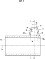
- Fig. 1 is a schematic cross-sectional view showing an example of an embodiment of the silencing system having the silencing structure according to the embodiment of the present invention.
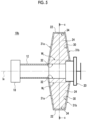
- Fig. 2 is a cross-sectional view taken along a line b-b of Fig. 1 .
- Fig. 3 is a perspective view of the silencing structure of Fig. 1 .
- Fig. 1 shows a cross section that is parallel to an axial direction of a central axis Ix of a tubular member 12 and passes through the center of a connection hole 12a (opening portion 32).
- this cross section will also be referred to as a "transverse cross section”.
- Fig. 1 shows a cross section that is parallel to an axial direction of a central axis Ix of a tubular member 12 and passes through the center of a connection hole 12a (opening portion 32).
- this cross section will also be referred to as a "transverse cross section”.
- FIG. 2 shows a cross section perpendicular to the axial direction of the central axis Ix of the tubular member 12.
- this cross section will also be referred to as a "front cross section”.
- the axial direction of the central axis Ix of the tubular member 12 is also simply referred to as "axial direction”.
- the silencing system 10 includes the cylindrical tubular member 12 and a silencing structure 22 disposed on an outer peripheral portion of the tubular member 12.
- the silencing structure 22 includes a cavity portion 30, the opening portion 32, and a closing portion 34, and may silence a sound by generating Helmholtz resonance or air column resonance, or may silence the sound by converting sound energy into thermal energy without the resonance.
- the tubular member 12 is, for example, a ventilation sleeve, such as a ventilation port and an air conditioning duct.
- tubular member 12 is not limited to the ventilation port, the air conditioning duct, and the like, and may be a general duct used in various devices.
- a wall of a house such as an apartment, includes, for example, a concrete wall, a gypsum board, a heat insulating material, a decorative plate, and a wallpaper, and the ventilation sleeve is provided through the concrete wall, the gypsum board, the heat insulating material, the decorative plate, and the wallpaper.
- the silencing structure according to the embodiment of the present invention can be suitably applied to such a ventilation sleeve of the wall.
- a cross-sectional shape of the ventilation sleeve is not limited to a circular shape, and may be various shapes, such as a quadrangular shape and a triangular shape.
- the cross-sectional shape of the ventilation sleeve does not have to be constant in the axial direction of the central axis of the ventilation sleeve. In other words, a diameter of the ventilation sleeve may be changed in the axial direction.
- the diameter (circle-equivalent diameter) of the ventilation sleeve is about 70 mm to 160 mm.
- an average inner diameter (weighted average) of the ventilation sleeve need only be about 70 mm to 160 mm.
- an inner diameter of the ventilation sleeve is measured with a resolution of 1 mm.
- the inner diameter is obtained by converting an area as a circle-equivalent area into a diameter.
- the unevenness is averaged.
- connection hole 12a that penetrates from the inside to the outside of the tubular member 12 is formed in a part of an outer peripheral surface of the tubular member 12.
- a size of the connection hole 12a is substantially the same as a size of the opening portion 32 of the silencing structure 22 described below.
- the silencing structure 22 has an outer shape which is a substantially square frustum shape, includes the cavity portion 30 inside, and a bottom surface of the square frustum is open to form the opening portion 32. In addition, a surface facing the opening portion 32 is closed to form the closing portion 34.
- the cavity portion 30 is formed in a shape substantially similar to the outer shape of the silencing structure 22. In other words, the cavity portion 30 has a substantially square frustum shape.
- two surfaces (31a and 31b) facing to each other in the axial direction are inclined with respect to a line segment orthogonal to the central axis Ix of the tubular member 12 as viewed in the transverse cross section.
- the silencing structure 22 is disposed on the outer peripheral surface of the tubular member 12 with the opening portion 32 aligned with a position of the connection hole 12a of the tubular member 12. Therefore, a bottom portion (surface on the opening portion 32 side) of the silencing structure 22 is a curved surface along the outer peripheral surface of the tubular member 12.
- a width of the cavity portion 30 is narrowed as a distance from the opening portion 32 is increased. That is, a width Wi of the cavity portion 30 on the opening portion 32 side is wider than a width W 2 on the closing portion 34 side and is gradually narrowed toward the closing portion 34 side.
- a width of the cavity portion 30 is narrowed as a distance from the opening portion 32 is increased. That is, a width W 3 of the cavity portion 30 on the opening portion 32 side is wider than a width W 4 on the closing portion 34 side and is gradually narrowed toward the closing portion 34 side.
- a cross-sectional area of the cavity portion 30 on the opening portion 32 side is larger than a cross-sectional area of the cavity portion 30 on the closing portion 34 side.
- the cross-sectional area of the cavity portion 30 on the opening portion 32 side in a case in which a cross-sectional shape of the tubular member 12 is a circular shape or the like and a surface of the silencing structure on the opening portion 30 side is a curved surface, the cross-sectional area of the cavity portion 30 on a tangent plane with the tubular member 12 at the center position of the opening portion 32 is the cross-sectional area of the cavity portion 30 on the opening portion 32 side. Therefore, the width W 3 of the cavity portion 30 on the opening portion 32 side is a width of the cavity portion 30 on a tangent line with the tubular member 12 at the center position of the opening portion 32.
- the cross-sectional area of the cavity portion 30 on the closing portion 34 side is the cross-sectional area of the cavity portion 30 that is parallel to a plane on which the cross-sectional area of the cavity portion 30 on the opening portion 32 side is obtained and that is closed to the closing portion 34 side.
- the opening portion 32 is narrowed (narrower than the width of the cavity portion 30), for example, in a case in which the opening portion 32 is partially closed by an air volume adjusting member 20, the cross-sectional area of the cavity portion 30 at the position closest to the opening portion 32 is the cross-sectional area of the cavity portion 30 on the opening portion 32 side.
- the silencing structure according to the embodiment of the present invention has the configuration in which, at least one of the cross section (front cross section) perpendicular to the axial direction of the tubular member 12 or the cross section (transverse cross section) parallel to the axial direction of the tubular member 12, the width of the cavity portion 30 is narrowed as the distance from the opening portion 32 is increased, so that the configuration is adopted in which the cross-sectional area of the cavity portion 30 on the opening portion 32 side is larger than the cross-sectional area of the cavity portion 30 on the closing portion 34 side.
- a sound absorbance in a low frequency region can be further increased without increasing a volume of the silencing structure.
- a mechanism of the effect of capable of increasing the sound absorbance in the low frequency region is estimated as follows.
- the sound absorbance in the low frequency region can be further increased.
- a sound absorbing effect of a porous sound absorbing material is weakened in the low frequency region, the sound absorbing effect is not higher in the low frequency region than in a high frequency region.
- the configuration is adopted in which the silencing system 10 includes one silencing structure 22, but the present invention is not limited to this, and a configuration may be adopted in which the silencing system 10 includes two or more silencing structures 22.
- the respective silencing structure 22 may be disposed at different positions in a circumferential direction (hereinafter, also simply referred to as the circumferential direction) of the tubular member 12, or may be disposed at different positions in the axial direction of the tubular member 12.
- the configuration is adopted in which the silencing structure 22 is disposed on the outer peripheral surface of the tubular member 12, but the present invention is not limited to this as long as the silencing structure 22 is disposed at a position at which a sound passing through the tubular member 12 and/or a sound generated by the tubular member 12 can be silenced.
- the silencing structure 22 may be disposed in the vicinity of an end surface of the tubular member 12.
- the silencing structure 22 may be disposed inside the tubular member 12.
- Fig. 5 shows a cross-sectional view conceptually showing another example of the silencing system according to the embodiment of the present invention.
- Fig. 6 shows a cross-sectional view taken along the line c-c of Fig. 5 .
- a silencing system 10b shown in Figs. 5 and 6 includes the tubular member 12 and two silencing structures 22 disposed at a position at which the outer peripheral portion of the tubular member 12 on one end surface side of the tubular member 12 is extended.
- the silencing system 10b includes a soundproof hood 18 disposed on an end surface of the tubular member 12 on a side opposite to the end surface on the side on which the silencing structure 22 is disposed, and the air volume adjusting member 20 disposed at a position of the silencing structure 22 on a side opposite to the tubular member 12, which is a position passing through the central axis Ix of the tubular member 12.
- the silencing structure 22 includes a porous sound absorbing material 24 in the cavity portion 30.
- the soundproof hood 18 is a louver or the like that is known in the related art and is installed in the ventilation port, the air conditioning duct, or the like.
- the air volume adjusting member 20 is a register or the like that is known in the related art.
- the two silencing structures 22 are disposed at the same position in the axial direction but at different positions in a circumferential direction (positions deviated by 180°).
- the two silencing structures 22 are formed as a part of two components (23a and 23b) having a truncated cone shape, by aligning the bottom surfaces of the two components with each other to form a space inside.
- One component 23a forms one silencing structure 22 and the other component 23b forms the other silencing structure 22.
- a width of an end side in contact with the other component is equal to or larger than the diameter of the tubular member 12.
- semicircular notches (25a and 25b) having a diameter substantially the same as the diameter of the tubular member 12 are formed at the end parts of the two components (23a and 23b) on a side in contact with the other component of a surface on the tubular member 12.
- semicircular notches into which the air volume adjusting member 20 is fitted are formed respectively on the end parts on the side in contact with the other component of the surface on a side opposite to the tubular member 12 of the two components (23a and 23b), and the opening into which the air volume adjusting member 20 is fitted is formed in a case in which the two components (23a and 23b) are combined.
- the soundproof hood 18, the tubular member 12, the two components (23a and 23b), and the air volume adjusting member 20 are in a state of communicating with each other, so that the ventilation can be performed between the soundproof hood 18 side and the air volume adjusting member 20 side.
- the two components (23a and 23b) also function as a part of the tubular member.
- the width of the cavity portion 30 is narrowed as a distance from the opening portion 32 is increased. That is, the width W 1 of the cavity portion 30 on the opening portion 32 side is wider than the width W 2 on the closing portion 34 and is gradually narrowed toward the closing portion 34 side.
- the width of the cavity portion 30 is narrowed as the distance from the opening portion 32 is increased. That is, the width W 3 of the cavity portion 30 on the opening portion 32 side is wider than the width W 4 on the closing portion 34 side and is gradually narrowed toward the closing portion 34 side.
- the cross-sectional area of the cavity portion 30 on the opening portion 32 side is larger than the cross-sectional area of the cavity portion 30 on the closing portion 34 side.
- the sound absorbance in the low frequency region can be further increased without increasing the volume of the silencing structure.
- the shape of the silencing structure 22 is the substantially square frustum shape
- a configuration is adopted in which the cross-sectional area of the cavity portion 30 on the opening portion 32 side is larger than the cross-sectional area of the cavity portion 30 on the closing portion 34 side
- a configuration may be adopted in which the width of the cavity portion 30 is narrowed as the distance from the opening portion 32 is increased in at least one of the cross section (front cross section) perpendicular to the axial direction of the tubular member 12 or the cross section (transverse cross section) parallel to the axial direction of the tubular member 12.
- the shape of the silencing structure 22 may be a substantially truncated cone shape, a polygonal frustum shape, or the like.
- a side surface surface other than the surface having the opening portion and the closing portion
- the shape of the silencing structure 22 may be a shape in which any one of the side surfaces of the square pillar of the trapezoid is used as the opening portion.
- the shape of the transverse cross section may be a rectangular shape in which the surface 31a and the surface 31b are not inclined as shown in Fig. 7
- the shape of the front cross section may be a trapezoidal shape in which the surface 31c is inclined and the surface 31d is not inclined as shown in Fig. 8 . It should be noted that Fig.
- Fig. 7 is a diagram schematically showing the shape of the transverse cross section in a case in which the two silencing structures 22 are provided, as in Fig. 5
- Fig. 8 is a diagram schematically showing the shape of the front cross section in a case in which the two silencing structures 22 are provided, as in Fig. 6 .
- Figs. 9 to 12 the trapezoidal shape is adopted in which the surface 31c is inclined and the surface 31d is not inclined, but a trapezoidal shape may be adopted in which the surface 31d is inclined and the surface 31c is not inclined.
- the width of the cavity portion is narrowed as the distance from the opening portion is increased.
- the shape of the transverse cross section may be the rectangular shape in which the surface 31a and the surface 31b are not inclined as shown in Fig. 7
- the shape of the front cross section may be a trapezoidal shape in which the surface 31c and the surface 31d are inclined as shown in Fig. 9 .
- the width of the cavity portion is narrowed as the distance from the opening portion is increased.
- An inclination angle ⁇ 1 of the surface 31c and an inclination angle ⁇ 2 of the surface 31d may be the same as or different from each other.
- the shape of the transverse cross section may be a trapezoidal shape in which the surface 31a is inclined and the surface 31b is not inclined as shown in Fig. 10
- the shape of the front cross section may be a rectangular shape in which the surface 31c and the surface 31d are not inclined as shown in Fig. 11 .
- the trapezoidal shape is adopted in which the surface 31a is inclined and the surface 31b is not inclined, but a trapezoidal shape may be adopted in which the surface 31b is inclined and the surface 31a is not inclined.
- the width of the cavity portion is narrowed as the distance from the opening portion is increased.
- the shape of the transverse cross section may be a trapezoidal shape in which the surface 31a and the surface 31b are inclined as shown in Fig. 12
- the shape of the front cross section may be the rectangular shape in which the surface 31c and the surface 31d are not inclined as shown in Fig. 11 .
- the width of the cavity portion is narrowed as the distance from the opening portion is increased.
- An inclination angle ⁇ 3 of the surface 31a and an inclination angle ⁇ 4 of the surface 31b may be the same as or different from each other.
- the shape of the front cross section of the silencing structure 22 may be an annular shape (donut shape).
- the shape of the transverse cross section may be the trapezoidal shape in which the surface 31a is inclined and the surface 31b is not inclined as shown in Fig. 10 , or may be the trapezoidal shape in which the surface 31a and the surface 31b are inclined as shown in Fig. 12 .
- the width of the cavity portion is narrowed as the distance from the opening portion is increased.
- angles formed by line segments that are in contact with a vertex of the cavity portion that is not in contact with the opening portion both are approximately 90°.
- the silencing structure according to the embodiment of the present invention has the configuration in which the width of the cavity portion is narrowed as the distance from the opening portion is increased in at least one of the cross section (front cross section) perpendicular to the axial direction of the tubular member or the cross section (transverse cross section) parallel to the axial direction of the tubular member, at least one angle formed by the line segments that are in contact with the vertex of the cavity portion that is not in contact with the opening portion is larger than 90° ( ⁇ /2 [rad]), as shown in Fig. 15 .
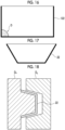
- the angles formed by the line segments that are in contact with the vertex of the cavity portion that is not in contact with the opening portion is approximately 90°. Therefore, as shown in Fig. 16 , the dirt, the mildew, and the like (reference numeral D) are likely to accumulate in a corner portion of the cavity portion on the side that is not in contact with the opening portion. In addition, it is difficult to remove the dirt, the mildew, and the like.
- At least one angle formed by the line segments that are in contact with the vertex of the cavity portion that is not in contact with the opening portion is larger than 90°. Therefore, as shown in Fig. 17 , the dirt, the mildew, and the like are less likely to accumulate in the corner portion of the cavity portion on the side that is not in contact with the opening portion. In addition, it is easy to remove the dirt, the mildew, and the like. In addition, moisture is less likely to accumulate in the corner portion and is likely to dry.
- the silencing structure according to the embodiment of the present invention has the configuration in which the width of the cavity portion is narrowed as the distance from the opening portion is increased in at least one of the cross section (front cross section) perpendicular to the axial direction of the tubular member or the cross section (transverse cross section) parallel to the axial direction of the tubular member, and at least one of the surfaces (31a to 31d) that are in contact with the opening portion is inclined. Therefore, as shown in Fig.
- the silencing structure 22 in a case in which the silencing structure 22 is manufactured by using molds (Da and Db) as in injection molding or the like, since the surface in contact with the opening portion is inclined, there is a gradient, and the silencing structure 22 can be easily released from the mold after mold.
- the silencing structure 22 can be appropriately manufactured by injection molding, the silencing structure 22 can be manufactured easily and at low cost as compared with a case in which the silencing structure 22 is manufactured by another processing method such as cutting.
- the silencing structure according to the embodiment of the present invention at least one of the surfaces (31a to 31d) that are in contact with the opening portion is inclined, and thus the plurality of silencing structures 22 having the same shape can be superimposed on each other, as shown in Fig. 20 . Therefore, the volume can be reduced during transportation or the like, and the transportation efficiency can be improved.
- a total angle of the inclination angle ⁇ 1 of the surface 31c and the inclination angle ⁇ 2 of the surface 31d and a total angle of the inclination angle ⁇ 3 of the surface 31a and the inclination angle ⁇ 4 of the surface 31b are preferably in a range of 0.1° to 20°, more preferably in a range of 1° to 16°, and still more preferably in a range of 2° to 12°.
- the area of the opening portion, a height of the cavity portion, and the like need only be appropriately set according to a silencing mechanism of the silencing structure, the frequency band to be silenced, and the like.
- the respective silencing structures consist of the components (23a and 23b) having the same shape as shown in Fig. 21
- the component 23a and the component 23b can be separated (see Fig. 22 ) and superimposed as shown in Fig. 23 . Therefore, the volume can be reduced during transportation or the like, and the transportation efficiency can be improved.
- the mold can be shared, so that the cost can be reduced.
- the two silencing structures are formed by one mold.
- the two silencing structures may have different shapes.
- the silencing structure according to the embodiment of the present invention has a rib structure.
- Fig. 24 shows another example of the silencing structure according to the embodiment of the present invention.
- a silencing structure 22b shown in Fig. 24 has a rib structure 36 on each of the surfaces (31a to 31d) adjacent to the opening portion.
- the component constituting the silencing structure is not a completely rigid body, for example, there is a concern that one surface constituting the silencing structure may vibrate to transmit sound.
- the rib structure to the silencing structure and increasing the rigidity of each part of the silencing structure, the resonance frequency of the component constituting the silencing structure can be increased, and the sound absorption property in the low frequency region can be improved.
- Fig. 25 is a flat plate 80 that has no rib structure.
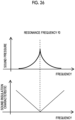
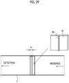
- Fig. 29 in a case in which such a plate 80 is disposed inside a cylindrical member F, the sound wave is incident from one end part of the cylindrical member F, and the sound pressure is measured at the other end part, as schematically shown in an upper graph of Fig. 26 , the sound pressure at a resonance frequency f0 of the plate 80 is increased, and the sound pressure is lowered as the distance from the resonance frequency f0 is increased. That is, as schematically shown in a lower graph of Fig. 26 , the sound insulation characteristic of the plate 80 is lowered at the resonance frequency f 0 .
- the resonance frequency of the plate 81 is moved to the high frequency side, the sound pressure is increased at a frequency fi, and the sound pressure is lowered as the distance from the resonance frequency fi is increased. That is, as schematically shown in a lower graph of Fig. 28 , the sound insulation characteristic of the plate 81 is lowered at the resonance frequency f 1 higher than the resonance frequency f 0 of the flat plate 80. In this case, since the sound insulation characteristic is improved as the distance from the resonance frequency is increased, the sound insulation characteristic in the low frequency region is higher in the plate 81 to which the rib structure 36 is applied.
- the resonance frequency of the component constituting the silencing structure can be increased, and the sound absorption property in the low frequency region can be improved.
- Fig. 30 shows a graph in which a relationship between the frequency and a transmission loss is obtained by changing a height of the rib structure using a calculation model having the configuration as shown in Fig. 29 .
- the cylindrical member F has an opening area of 10 cm ⁇ 10 cm and a length of 30 cm.
- the plate 81 has a size of 10 cm ⁇ 10 cm and a thickness of 2 mm.
- a rib height H is calculated at 0 mm, 2 mm, 3 mm, and 5 mm, respectively.
- an acoustic module of the finite element method calculation software COMSOL ver5.5 (COMSOL) is used for a simulation.
- the rib structure is disposed to extend in a height direction of the surface adjacent to the opening portion, but the present invention is not limited to this, and the rib structure may be disposed to extend in a width direction of the surface adjacent to the opening portion or may be disposed obliquely.
- the rib structure is applied to each surface adjacent to the opening portion one by one, but the present invention is not limited to this, and a plurality of rib structures may be applied to each surface.
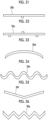
- the rib structure has a linear shape, but the present invention is not limited to this.
- the rib structure may be a branched structure.
- the rib structure may have curved shape.
- the rib structure may have a wavy shape.
- the rib structure may have a shape bent in the middle.
- the rib structure may have a triangular wave shape.
- a shape, a position, the number, and the like of the rib structure may be the same or different for each surface.
- Examples of a material for forming the silencing structure include a metal material, a resin material, a reinforced plastic material, and a carbon fiber.
- Examples of the metal material include metal materials, such as aluminum, titanium, magnesium, tungsten, iron, steel, chromium, chromium molybdenum, nichrome molybdenum, and alloys thereof.
- examples of the resin material include resin materials, such as an acrylic resin, polymethyl methacrylate, polycarbonate, polyamide-imide, polyarylate, polyetherimide, polyacetal, polyether ether ketone, polyphenylene sulfide, polysulfone, polyethylene terephthalate, polybutylene terephthalate, polyimide, and triacetyl cellulose.
- examples of the reinforced plastic material include carbon fiber reinforced plastics (CFRP) and glass fiber reinforced plastics (GFRP).
- the resin material As the material of the silencing structure. Also, as described above, from the viewpoint of sound insulation in the low frequency region, it is preferable to use a material having high rigidity. From the viewpoints of weight reduction and sound insulation, it is preferable that a density of the members constituting the silencing structure is 0.5 g/cm 3 to 2.5 g/cm 3 .
- the silencing structure according to the embodiment of the present invention may include the porous sound absorbing material in the cavity portion.
- the porous sound absorbing material is not particularly limited, and the sound absorbing material that is known in the related art can be appropriately used.
- various known sound absorbing material can be used, such as foam materials and materials containing minute air such as urethane foam, soft urethane foam, wood, ceramic particle sintered material, and phenol foam; fibers and nonwoven fabric materials such as glass wool, rock wool, microfibers (Thinsulate manufactured by 3M), a floor mat, a carpet, a meltblown nonwoven fabric, a metal nonwoven fabric, a polyester nonwoven fabric, metal wool, felt, an insulation board and a glass nonwoven fabric; wood wool cement board; nanofiber materials such as silica nanofiber; and gypsum board.
- foam materials and materials containing minute air such as urethane foam, soft urethane foam, wood, ceramic particle sintered material, and phenol foam
- fibers and nonwoven fabric materials such as glass wool, rock wool, microfibers (Thinsulate manufactured by 3M), a floor mat, a carpet,
- the disposition of the silencing structure with respect to the tubular member is not particularly limited as long as the sound can be appropriately silenced at the position, but it is preferable that the silencing structure is disposed not to occupy 50% or more of the cross-sectional area perpendicular to the axial direction of the tubular member. As a result, the ventilation property of the tubular member can be ensured.
- the silencing structure according to the embodiment of the present invention may have another commercially available soundproof member.
- an insertion type silencer installed inside the ventilation sleeve may be provided, or an outdoor-installation type silencer installed in the end part of the ventilation sleeve may be provided.
- a simulation was performed on a configuration in which the two silencing structures 22 were disposed on the outer peripheral surface of the tubular member 12.
- the porous sound absorbing material 24 was disposed in the cavity portion of the silencing structure 22.
- the soundproof hood 18 was disposed on the opening surface of the tubular member 12 on a side opposite to the side on which the silencing structure 22 was installed, and the register (air volume adjusting member) was disposed on the surface of the silencing structure 22 on a side opposite to the tubular member 12.
- a soundproof hood (BON-TS) manufactured by SYLPHA Corporation was modeled.
- a register (KRP-BWF) manufactured by UNIX Co., Ltd. was modeled.
- the inner diameter of the tubular member 12 was 100 mm, and the length thereof was 300 mm.
- the height of the cavity portion of the silencing structure 22 from the inner diameter of the tubular member 12 was 220 mm.
- a flow resistance of the porous sound absorbing material 24 was 2650 [Pa ⁇ s/m 2 ].
- a diameter of a portion of the register to be inserted into the silencing structure was 150 mm.
- the transverse cross section of the silencing structure 22 had the rectangular shape in which the surface 31a and the surface 31b were not inclined as shown in Fig. 7
- the front cross section had the shape in which the surface 31c was inclined at the angle ⁇ 1 and the surface 31d was not inclined as shown in Fig. 8
- the inclination angle ⁇ 1 of the surface 31c was changed to each of 0°, 2°, 6°, and 10°.
- a case in which the inclination angle ⁇ 1 was 0° is Comparative Example, and cases in which the inclination angle ⁇ 1 was 2°, 6°, and 10° are Examples.
- the width of the cavity portion in the transverse cross section was 86 mm
- the width of the cavity portion in the front cross section was 251 mm in a case in which the inclination angle ⁇ 1 of the surface 31c was 0°
- the width the cavity portion (opening portion) was adjusted such that the volume of the cavity portion was constant in a case in which the inclination angle of the surface 31c was changed.
- the cavity portion had the width W 3 on the opening portion side that was 253 mm and the cross-sectional area that was 21578 mm 2 , and had the width W 4 on the closing portion side that was 246.5 mm and the cross-sectional area that was 21199 mm 2 .
- the cavity portion had the width W 3 on the opening portion side that was 258 mm and the cross-sectional area that was 22188 mm 2 , and had the width W 4 on the closing portion side that was 237.5 mm and the cross-sectional area that was 20425 mm 2 .
- the width W 3 of the cavity portion on the opening portion side was 263.5 mm and the cross-sectional area was 22661 mm 2
- the width W 4 on the closing portion was 229.5 mm and the cross-sectional area was 19737 mm 2 .
- the sound wave was incident from a hemispherical surface in one space, and the amplitude of the sound wave reaching the hemispherical surface in the other space was obtained per unit volume.
- the hemispherical surface was a hemispherical surface having a radius of 500 mm about the center position of the opening surface of the tubular member.
- the amplitude of the incident sound wave per unit volume was 1.
- Fig. 38 shows a graph showing the relationship between the frequency and the transmission loss.
- Fig. 39 shows a change amount of the transmission loss in a case in which the inclination angle ⁇ 1 was 0°, as a graph.
- the transmission loss was increased as compared with a case in which the inclination angle ⁇ 1 was 0°. That is, it can be seen that the sound absorption property in the low frequency region was improved.
- a simulation was performed in the same manner as in the simulation 1 except that, as shown in Fig. 9 , the front cross section of the silencing structure 22 had the shape in which the surface 31c was inclined at the angle ⁇ 1 and the surface 31d was inclined at the angle ⁇ 2 , and the inclination angles ⁇ 1 and ⁇ 2 were changed to each of 0°, 2°, 6°, and 10°.
- a case in which the inclination angles ⁇ 1 and ⁇ 2 were 0° is Comparative Example, and cases in which the inclination angles ⁇ 1 and ⁇ 2 were 2°, 6°, and 10° are Examples.
- the width of the cavity portion in the front cross section was 251 mm in a case in which the inclination angle ⁇ 1 of the surface 31c and the inclination angle ⁇ 2 of the surface 31d were 0°, and the width of the cavity portion was adjusted such that the volume of the cavity portion was constant in a case in which the inclination angles ⁇ 1 and ⁇ 2 was changed.
- the cavity portion had the width W 3 on the opening portion side that was 255 mm and the cross-sectional area that was 21930 mm 2 , and had the width W 4 on the closing portion side that was 242 mm and the cross-sectional area that was 20812 mm 2 .
- the cavity portion had the width W 3 on the opening portion side that was 265 mm and the cross-sectional area that was 22790 mm 2 , and had the width W 4 on the closing portion side that was 224 mm and the cross-sectional area that was 19264 mm 2 .
- the cavity portion had the width W 3 on the opening portion side that was 276 mm and the cross-sectional area that was 23736 mm 2 , and had the width W 4 on the closing portion side that was 208 mm and the cross-sectional area that was 17888 mm 2 .
- Fig. 40 shows a graph showing the relationship between the frequency and the transmission loss.
- Fig. 41 shows a change amount of the transmission loss in a case in which the inclination angles ⁇ 1 and ⁇ 2 were 0°, as a graph.
- the transmission loss was increased as compared with a case in which the inclination angles ⁇ 1 and ⁇ 2 were 0°. That is, it can be seen that the sound absorption property in the low frequency region was improved.
- a simulation was performed in the same manner as in the simulation 1 except that, as shown in Fig. 12 , the transverse cross section of the silencing structure 22 has the shape in which the surface 31a was inclined at the angle ⁇ 3 and the surface 31b was inclined at the angle ⁇ 4 , and as shown in Fig. 9 , the front cross section of the silencing structure 22 had the shape in which the surface 31c was inclined at the angle ⁇ 1 and the surface 31d was inclined at the angle ⁇ 2 , and the inclination angles ⁇ 1 to ⁇ 4 were changed to each of 0°, 2°, 6°, and 10°.
- a case in which the inclination angles ⁇ 1 to ⁇ 4 were 0° is Comparative Example, and cases in which the inclination angles ⁇ 1 to ⁇ 4 were 2°, 6°, and 10° are Examples.
- the width of the cavity portion in the transverse cross section was 86 mm in a case in which the inclination angle ⁇ 3 of the surface 31a and the inclination angle ⁇ 4 of the surface 31b were 0°, and the inclination angles ⁇ 3 and ⁇ 4 were changed.
- the width W 1 and the width W 2 were adjusted such that the width at the center position in the height direction was constant.
- the width of the cavity portion in the front cross section was 251 mm in a case in which the inclination angle ⁇ 1 of the surface 31c and the inclination angle ⁇ 2 of the surface 31d were 0°, and the width W 3 and the width W 4 of the cavity portion in the front cross section were adjusted such that the width at the center position in the height direction was constant in a case in which the inclination angles ⁇ 1 and ⁇ 2 were changed.
- the cavity portion had the width W 1 on the opening portion side that was 90 mm and the width W 2 on the closing portion side that was 77 mm in the transverse cross section, and the cavity portion had the width W 3 on the opening portion side that was 255 mm and the width W 4 on the closing portion side that was 242 mm in the front cross section. Therefore, the cross-sectional area of the cavity portion on the opening portion side was 22950 mm 2 , and the cross-sectional area of the cavity portion on the closing portion side was 18634 mm 2 .
- the cavity portion had the width W 1 on the opening portion side that was 100 mm and the width W 2 on the closing portion side that was 59 mm in the transverse cross section, and the cavity portion had the width W 3 on the opening portion side that was 265 mm and the width W 4 on the closing portion side that was 224 mm in the front cross section. Therefore, the cross-sectional area of the cavity portion on the opening portion side was 13216 mm 2 , and the cross-sectional area of the cavity portion on the closing portion side was 26500 mm 2 .
- the cavity portion had the width W 1 on the opening portion side that was 110 mm and the width W 2 on the closing portion side that was 42 mm in the transverse cross section, and the cavity portion had the width W 3 on the opening portion side that was 276 mm and the width W 4 on the closing portion side that was 208 mm in the front cross section. Therefore, the cross-sectional area of the cavity portion on the opening portion side was 30360 mm 2 , and the cross-sectional area of the cavity portion on the closing portion side was 8736 mm 2 .
- Fig. 42 shows a graph showing the relationship between the frequency and the transmission loss.
- Fig. 43 shows a change amount of the transmission loss in a case in which the inclination angles ⁇ 1 and ⁇ 2 were 0°, as a graph.
- the transmission loss was increased as compared with a case in which the inclination angles ⁇ 1 to ⁇ 4 were 0°. That is, it can be seen that the sound absorption property in the low frequency region was improved.
- a simulation was performed in the same manner as in the simulation 1 except that, as shown in Fig. 10 , the transverse cross section of the silencing structure 22 has the shape in which the surface 31a was inclined at the angle ⁇ 3 and the surface 31b was not inclined, and as shown in Fig. 11 , the front cross section of the silencing structure 22 had the rectangular shape in which the surface 31c and the surface 31d were not inclined, and the inclination angle ⁇ 3 was changed to each of 0°, 2°, 6°, and 10°.
- a case in which the inclination angle ⁇ 3 was 0° is Comparative Example, and cases in which the inclination angle ⁇ 3 was 2°, 6°, and 10° are Examples.
- the width of the cavity portion in the transverse cross section was 86 mm in a case in which the inclination angle ⁇ 3 of the surface 31a was 0°, and the width of the cavity portion (opening portion) was adjusted such that the volume of the cavity portion was constant in a case in which the inclination angles ⁇ 3 was changed.
- the width of the cavity portion in the front cross section was 251 mm.
- the cavity portion had the width W 1 on the opening portion side that was 88 mm and the cross-sectional area that was 22088 mm 2 , and had the width W 2 on the closing portion side that was 82 mm and the cross-sectional area that was 20457 mm 2 .
- the cavity portion had the width W 1 on the opening portion side that was 93 mm and the cross-sectional area that was 23343 mm 2 , and had the width W 3 on the closing portion side that was 72.5 mm and the cross-sectional area that was 18198 mm 2 .
- the cavity portion had the width W 1 on the opening portion side that was 98 mm and the cross-sectional area that was 24598 mm 2 , and had the width W 2 on the closing portion side that was 64 mm and the cross-sectional area that was 16064 mm 2 .
- Fig. 44 shows a graph showing the relationship between the frequency and the transmission loss.
- Fig. 45 shows a change amount of the transmission loss in a case in which the inclination angle ⁇ 3 was 0°, as a graph.
- the transmission loss was increased as compared with a case in which the inclination angle ⁇ 3 was 0°. That is, it can be seen that the sound absorption property in the low frequency region was improved.
- a simulation was performed in the same manner as in the simulation 1 except that, as shown in Fig. 12 , the transverse cross section of the silencing structure 22 has the shape in which the surface 31a was inclined at the angle ⁇ 3 and the surface 31b was inclined at the angle ⁇ 4 , and as shown in Fig. 11 , the front cross section of the silencing structure 22 had the rectangular shape in which the surface 31c and the surface 31d were not inclined, and the inclination angles ⁇ 3 and ⁇ 4 were changed to each of 0°, 2°, 6°, and 10°.
- a case in which the inclination angles ⁇ 3 and ⁇ 4 were 0° is Comparative Example, and cases in which the inclination angles ⁇ 3 and ⁇ 4 were 2°, 6°, and 10° are Examples.
- the width of the cavity portion in the transverse cross section was 86 mm in a case in which the inclination angle ⁇ 3 of the surface 31a and the inclination angle ⁇ 4 of the surface 31b were 0°, and the width of the cavity portion in the front cross section was adjusted such that the volume of the cavity portion (opening portion) was constant in a case in which the inclination angles ⁇ 3 and ⁇ 4 were changed.
- the width of the cavity portion in the front cross section was 251 mm.
- the cavity portion had the width W 1 on the opening portion side that was 90 mm and the cross-sectional area that was 22590 mm 2 , and had the width W 2 on the closing portion side that was 77 mm and the cross-sectional area that was 19327 mm 2 .
- the cavity portion had the width W 1 on the opening portion side that was 100 mm and the cross-sectional area that was 25100 mm 2 , and had the width W 2 on the closing portion side that was 59 mm and the cross-sectional area that was 14809 mm 2 .
- the cavity portion had the width W 1 on the opening portion side that was 110 mm and the cross-sectional area that was 27610 mm 2 , and had the width W 2 on the closing portion side that was 42 mm and the cross-sectional area that was 10542 mm 2 .
- Fig. 46 shows a graph showing the relationship between the frequency and the transmission loss.
- Fig. 47 shows a change amount of the transmission loss in a case in which the inclination angles ⁇ 3 and ⁇ 4 were 0°, as a graph.
- the transmission loss was increased as compared with a case in which the inclination angles ⁇ 3 and ⁇ 4 were 0°. That is, it can be seen that the sound absorption property in the low frequency region was improved.
Landscapes
- Engineering & Computer Science (AREA)
- Chemical & Material Sciences (AREA)
- Combustion & Propulsion (AREA)
- Mechanical Engineering (AREA)
- General Engineering & Computer Science (AREA)
- Physics & Mathematics (AREA)
- Acoustics & Sound (AREA)
- Multimedia (AREA)
- Building Environments (AREA)
- Duct Arrangements (AREA)
Abstract
Description
- The present invention relates to a silencing structure and a silencing system.
- In a tubular member (ventilation sleeve) that penetrates between indoor and outdoor areas, such as a ventilation port and an air conditioning duct, which is provided on a wall that separates the indoor and outdoor areas, in order to suppress transmission of a noise from the outdoor area to the indoor area, or in order to suppress transmission of a noise from the indoor area to the outdoor area, a porous sound absorbing material made of urethane, polyethylene, or the like is installed in the ventilation sleeve.
- However, in a case in which the porous sound absorbing material made of urethane, polyethylene, or the like is used, an absorbance of a sound having a low frequency of 1000 Hz or less is extremely lowered. Therefore, in order to increase the absorbance, it is required to increase the volume. However, since it is required to ensure the ventilation property of the ventilation port, the air conditioning duct, or the like, a size of the porous sound absorbing material is limited, and there is a problem that it is difficult to achieve both high ventilation property and soundproof performance.
- In order to make soundproof of a noise having a low frequency of 1000 Hz or less using the porous sound absorbing material, an amount of the porous sound absorbing material is remarkably increased. Therefore, it is generally difficult to obtain sufficient soundproof performance even at the expense of ventilation.
- In addition, as a silencer, a resonance type silencer that silences a sound in the vicinity of a resonance frequency of the silencer is also proposed. However, in a case of the resonance type silencer, a length of at least 1/4 of a wavelength of the resonance frequency is required, and the size of the silencer is increased. Therefore, there is a problem that it is difficult to achieve both high ventilation property and soundproof performance. Also, the resonance type silencer silences a sound having a specific frequency. Therefore, the resonance sound to be silenced is limited to only one frequency, and a frequency band to be silenced by the resonance type silencer is narrow. Therefore, there is a problem that resonance sounds of other frequencies cannot be silenced.
- On the other hand, as a small-sized silencer capable of silencing in a wide band including a low frequency, a silencer that includes a cavity portion and an opening portion through which the cavity portion communicates with the ventilation sleeve, and silences the sound without using the resonance is proposed.
- For example,
JP2019-133122A - In the silencer that includes the cavity portion and the opening portion through which the cavity portion communicates with the ventilation sleeve and silences the sound without using the resonance, it is required to further increase a low frequency sound absorbance.
- The present invention is to solve the above-described problems of the related art and to provide a silencing structure and a silencing system having a high sound absorbance in a low frequency region.
- In order to solve this problems, the present invention has the configurations as follows.
- [1] A silencing structure that is installed in a tubular member, the silencing structure comprising a cavity portion, an opening portion through which the cavity portion communicates with the tubular member, and a closing portion that closes the cavity portion at a position facing the opening portion, in which a cross-sectional area of the cavity portion on a side of the opening portion is larger than a cross-sectional area of the cavity portion on a side of the closing portion.
- [2] The silencing structure according to [1], in which at least one angle formed by line segments that are in contact with a vertex of the cavity portion that is not in contact with the opening portion is larger than π/2 [rad].
- [3] The silencing structure according to [1] or [2], in which, in a cross section perpendicular to an axial direction of the tubular member, a width of the cavity portion is narrowed as a distance from the opening portion is increased.
- [4] The silencing structure according to any one of [1] to [3], in which the silencing structure has a rib structure.
- [5] The silencing structure according to any one of [1] to [4], in which a density of members constituting the silencing structure is 0.5 g/cm3 to 2.5 g/cm3.
- [6] The silencing structure according to any one of [1] to [5], in which a porous sound absorbing material is provided in the cavity portion.
- [7] A silencing system in which the silencing structure according to any one of [1] to [6] is installed in the tubular member, the silencing system comprising two or more silencing structures consisting of components having the same shape.
- [8] A silencing system in which the silencing structure according to any one of [1] to [6] is installed in the tubular member, the silencing system comprising two or more silencing structures, in which at least two silencing structures are formed by one mold.
- [9] A silencing system in which the silencing structure according to any one of [1] to [6] is installed in the tubular member, in which the silencing structure does not occupy 50% or more of a cross-sectional area perpendicular to an axial direction of the tubular member.
- According to the present invention, it is possible to provide the silencing structure and the silencing system having the high sound absorbance in the low frequency region.
-
-
Fig. 1 is a cross-sectional view conceptually showing an example of a silencing system having a silencing structure according to an embodiment of the present invention. -
Fig. 2 is a cross-sectional view taken along a line b-b ofFig. 1 . -
Fig. 3 is a perspective view of the silencing structure shown inFig. 1 . -
Fig. 4 is a perspective view showing another example of the silencing structure according to the embodiment of the present invention. -
Fig. 5 is a cross-sectional view conceptually showing a silencing system having another example of the silencing structure according to the embodiment of the present invention. -
Fig. 6 is a cross-sectional view taken along line c-c ofFig. 5 . -
Fig. 7 is a conceptual diagram for describing a shape of another example of the silencing structure. -
Fig. 8 is a conceptual diagram for describing the shape of another example of the silencing structure. -
Fig. 9 is a conceptual diagram for describing the shape of another example of the silencing structure. -
Fig. 10 is a conceptual diagram for describing the shape of another example of the silencing structure. -
Fig. 11 is a conceptual diagram for describing the shape of another example of the silencing structure. -
Fig. 12 is a conceptual diagram for describing the shape of another example of the silencing structure. -
Fig. 13 is a conceptual diagram for describing the shape of another example of the silencing structure. -
Fig. 14 is a diagram for describing a structure of a silencer in the related art. -
Fig. 15 is a diagram for describing a structure of the silencing structure according to the embodiment of the present invention. -
Fig. 16 is a diagram for describing a problem of a silencing structure in the related art. -
Fig. 17 is a diagram for describing another action of the silencing structure according to the embodiment of the present invention. -
Fig. 18 is a conceptual diagram for describing an action in a case of manufacturing the silencing structure. -
Fig. 19 is a diagram for describing a problem of the silencing structure in the related art. -
Fig. 20 is a diagram for describing another action of the silencing structure according to the embodiment of the present invention. -
Fig. 21 is a conceptual diagram showing an example of another configuration of the silencing structure according to the embodiment of the present invention. -
Fig. 22 is an exploded view of the silencing structure shown inFig. 21 . -
Fig. 23 is a conceptual diagram showing a state of a component constituting the silencing structure shown inFig. 21 during transportation. -
Fig. 24 is a perspective view conceptually showing another example of the silencing structure according to the embodiment of the present invention. -
Fig. 25 is a diagram showing a plate member that has no rib structure. -
Fig. 26 is a conceptual diagram of a graph of a sound pressure and a sound insulation characteristic for describing a resonance frequency due to the plate member shown inFig. 25 . -
Fig. 27 is a diagram showing a plate member having the rib structure. -
Fig. 28 is a conceptual diagram of a graph of the sound pressure and the sound insulation characteristic for describing the resonance frequency due to the plate member shown inFig. 27 . -
Fig. 29 is a diagram for describing a method of measuring a transmission loss due to the plate member. -
Fig. 30 is a graph showing a relationship between a frequency and the transmission loss. -
Fig. 31 is a diagram conceptually showing another example of the rib structure included in the silencing structure according to the embodiment of the present invention. -
Fig. 32 is a diagram conceptually showing another example of the rib structure included in the silencing structure according to the embodiment of the present invention. -
Fig. 33 is a diagram conceptually showing another example of the rib structure included in the silencing structure according to the embodiment of the present invention. -
Fig. 34 is a diagram conceptually showing another example of the rib structure included in the silencing structure according to the embodiment of the present invention. -
Fig. 35 is a diagram conceptually showing another example of the rib structure included in the silencing structure according to the embodiment of the present invention. -
Fig. 36 is a diagram conceptually showing another example of the rib structure included in the silencing structure according to the embodiment of the present invention. -
Fig. 37 is a diagram for describing a calculation model of a silencing system according to Examples. -
Fig. 38 is a graph showing a relationship between the frequency and the transmission loss. -
Fig. 39 is a graph showing the frequency and a change in the transmission loss. -
Fig. 40 is a graph showing a relationship between the frequency and the transmission loss. -
Fig. 41 is a graph showing the frequency and the change in the transmission loss. -
Fig. 42 is a graph showing a relationship between the frequency and the transmission loss. -
Fig. 43 is a graph showing the frequency and the change in the transmission loss. -
Fig. 44 is a graph showing a relationship between the frequency and the transmission loss. -
Fig. 45 is a graph showing the frequency and the change in the transmission loss. -
Fig. 46 is a graph showing a relationship between the frequency and the transmission loss. -
Fig. 47 is a graph showing the frequency and the change in the transmission loss. - The present invention will be described below in detail.
- The configuration requirements shown below are described based on a representative embodiment of the present invention, but the present invention is not limited to such an embodiment.
- It should be noted that, in the present specification, a numerical range represented by "to" means a range including numerical values described before and after "to" as a lower limit value and an upper limit value.
- Also, in the present specification, "orthogonal" and "parallel" include a range of errors allowed in the technical field to which the present invention belongs. For example, "orthogonal" and "parallel" mean that the it is within a range of less than ±10° with respect to strict orthogonality or parallelism, and the error with respect to strict orthogonality or parallelism is preferably 5° or less, and more preferably 3° or less.
- In the present specification, "the same" includes an error range generally allowed in the technical field.
- A silencing structure according to an embodiment of the present invention is a silencing structure that is installed in a tubular member, the silencing structure including a cavity portion, an opening portion through which the cavity portion communicates with the tubular member, and a closing portion that closes the cavity portion at a position facing the opening portion, in which a cross-sectional area of the cavity portion on an opening portion side is larger than a cross-sectional area of the cavity portion on a closing portion side.
- A silencing system according to the embodiment of the present invention is a silencing system in which the silencing structure is installed on the tubular member.
- In the silencing system according to the embodiment of the present invention, it is preferable that the installed silencing structure does not occupy 50% or more of a cross-sectional area perpendicular to an axial direction of the tubular member.
- The configurations of the silencing structure and the silencing system according to the embodiment of the present invention will be described with reference to the drawings.
-
Fig. 1 is a schematic cross-sectional view showing an example of an embodiment of the silencing system having the silencing structure according to the embodiment of the present invention.Fig. 2 is a cross-sectional view taken along a line b-b ofFig. 1 .Fig. 3 is a perspective view of the silencing structure ofFig. 1 . Specifically,Fig. 1 shows a cross section that is parallel to an axial direction of a central axis Ix of atubular member 12 and passes through the center of aconnection hole 12a (opening portion 32). Hereinafter, this cross section will also be referred to as a "transverse cross section". In addition,Fig. 2 shows a cross section perpendicular to the axial direction of the central axis Ix of thetubular member 12. Hereinafter, this cross section will also be referred to as a "front cross section". In addition, the axial direction of the central axis Ix of thetubular member 12 is also simply referred to as "axial direction". - As shown in
Figs. 1 and2 , the silencingsystem 10 includes thecylindrical tubular member 12 and a silencingstructure 22 disposed on an outer peripheral portion of thetubular member 12. The silencingstructure 22 includes acavity portion 30, the openingportion 32, and a closingportion 34, and may silence a sound by generating Helmholtz resonance or air column resonance, or may silence the sound by converting sound energy into thermal energy without the resonance. - The
tubular member 12 is, for example, a ventilation sleeve, such as a ventilation port and an air conditioning duct. - It should be noted that the
tubular member 12 is not limited to the ventilation port, the air conditioning duct, and the like, and may be a general duct used in various devices. - Among these, a wall of a house, such as an apartment, includes, for example, a concrete wall, a gypsum board, a heat insulating material, a decorative plate, and a wallpaper, and the ventilation sleeve is provided through the concrete wall, the gypsum board, the heat insulating material, the decorative plate, and the wallpaper. The silencing structure according to the embodiment of the present invention can be suitably applied to such a ventilation sleeve of the wall.
- It should be noted that a cross-sectional shape of the ventilation sleeve is not limited to a circular shape, and may be various shapes, such as a quadrangular shape and a triangular shape. In addition, the cross-sectional shape of the ventilation sleeve does not have to be constant in the axial direction of the central axis of the ventilation sleeve. In other words, a diameter of the ventilation sleeve may be changed in the axial direction.
- In addition, in a case of a ventilation sleeve for a residential use, the diameter (circle-equivalent diameter) of the ventilation sleeve is about 70 mm to 160 mm. In a case in which the diameter of the ventilation sleeve is changed in the axial direction, an average inner diameter (weighted average) of the ventilation sleeve need only be about 70 mm to 160 mm.
- It should be noted that an inner diameter of the ventilation sleeve is measured with a resolution of 1 mm. In a case in which the cross-sectional shape of the sleeve is not circular, the inner diameter is obtained by converting an area as a circle-equivalent area into a diameter. In a case of having a fine structure, such as unevenness of less than 1 mm, the unevenness is averaged.
- As shown in
Figs. 1 and2 , theconnection hole 12a that penetrates from the inside to the outside of thetubular member 12 is formed in a part of an outer peripheral surface of thetubular member 12. In the shown example, a size of theconnection hole 12a is substantially the same as a size of the openingportion 32 of the silencingstructure 22 described below. - As shown in
Fig. 3 , the silencingstructure 22 has an outer shape which is a substantially square frustum shape, includes thecavity portion 30 inside, and a bottom surface of the square frustum is open to form the openingportion 32. In addition, a surface facing the openingportion 32 is closed to form the closingportion 34. Thecavity portion 30 is formed in a shape substantially similar to the outer shape of the silencingstructure 22. In other words, thecavity portion 30 has a substantially square frustum shape. - Therefore, as shown in
Fig. 1 , among the surfaces (surfaces other than the closing portion 34) of the silencingstructure 22 in contact with the openingportion 32, two surfaces (31a and 31b) facing to each other in the axial direction are inclined with respect to a line segment orthogonal to the central axis Ix of thetubular member 12 as viewed in the transverse cross section. - In addition, as shown in
Fig. 2 , among the surfaces of the silencingstructure 22 in contact with the openingportion 32, remaining two surfaces (31c and 31d) are inclined with respect to a perpendicular line drawn from the center of thetubular member 12 to the surface of the silencingstructure 22 on the closing portion side as viewed in the front cross section. - As shown in
Figs. 1 and2 , the silencingstructure 22 is disposed on the outer peripheral surface of thetubular member 12 with the openingportion 32 aligned with a position of theconnection hole 12a of thetubular member 12. Therefore, a bottom portion (surface on the openingportion 32 side) of the silencingstructure 22 is a curved surface along the outer peripheral surface of thetubular member 12. - Here, in the transverse cross section of the silencing
structure 22, a width of thecavity portion 30 is narrowed as a distance from the openingportion 32 is increased. That is, a width Wi of thecavity portion 30 on the openingportion 32 side is wider than a width W2 on the closingportion 34 side and is gradually narrowed toward the closingportion 34 side. - In addition, in the front cross section of the silencing
structure 22, a width of thecavity portion 30 is narrowed as a distance from the openingportion 32 is increased. That is, a width W3 of thecavity portion 30 on the openingportion 32 side is wider than a width W4 on the closingportion 34 side and is gradually narrowed toward the closingportion 34 side. - Therefore, a cross-sectional area of the
cavity portion 30 on the openingportion 32 side is larger than a cross-sectional area of thecavity portion 30 on the closingportion 34 side. - It should be noted that, regarding the cross-sectional area of the
cavity portion 30 on the openingportion 32 side, as shown inFig. 2 , in a case in which a cross-sectional shape of thetubular member 12 is a circular shape or the like and a surface of the silencing structure on the openingportion 30 side is a curved surface, the cross-sectional area of thecavity portion 30 on a tangent plane with thetubular member 12 at the center position of the openingportion 32 is the cross-sectional area of thecavity portion 30 on the openingportion 32 side. Therefore, the width W3 of thecavity portion 30 on the openingportion 32 side is a width of thecavity portion 30 on a tangent line with thetubular member 12 at the center position of the openingportion 32. - In addition, the cross-sectional area of the
cavity portion 30 on the closingportion 34 side is the cross-sectional area of thecavity portion 30 that is parallel to a plane on which the cross-sectional area of thecavity portion 30 on the openingportion 32 side is obtained and that is closed to the closingportion 34 side. - It should be noted that, as shown in
Figs. 5 and6 described below, the openingportion 32 is narrowed (narrower than the width of the cavity portion 30), for example, in a case in which theopening portion 32 is partially closed by an airvolume adjusting member 20, the cross-sectional area of thecavity portion 30 at the position closest to the openingportion 32 is the cross-sectional area of thecavity portion 30 on the openingportion 32 side. - As described above, the silencing structure according to the embodiment of the present invention has the configuration in which, at least one of the cross section (front cross section) perpendicular to the axial direction of the
tubular member 12 or the cross section (transverse cross section) parallel to the axial direction of thetubular member 12, the width of thecavity portion 30 is narrowed as the distance from the openingportion 32 is increased, so that the configuration is adopted in which the cross-sectional area of thecavity portion 30 on the openingportion 32 side is larger than the cross-sectional area of thecavity portion 30 on the closingportion 34 side. As a result, a sound absorbance in a low frequency region can be further increased without increasing a volume of the silencing structure. - A mechanism of the effect of capable of increasing the sound absorbance in the low frequency region is estimated as follows.
- Since, as the cross-sectional area of the
cavity portion 30 on the openingportion 32 side is larger, an acoustic impedance in the vicinity of the openingportion 32 is lower, the sound wave is more likely to enter the silencing structure, and the effect is more likely to occur at a low frequency having a strong diffraction characteristic, it is estimated that the sound absorbance in the low frequency region can be further increased. However, since a sound absorbing effect of a porous sound absorbing material is weakened in the low frequency region, the sound absorbing effect is not higher in the low frequency region than in a high frequency region. - Here, in the examples shown in
Fig. 1 andFig. 2 , the configuration is adopted in which the silencingsystem 10 includes one silencingstructure 22, but the present invention is not limited to this, and a configuration may be adopted in which the silencingsystem 10 includes two or more silencingstructures 22. In a case of the configuration in which the silencingsystem 10 includes the two or more silencingstructures 22, the respective silencingstructure 22 may be disposed at different positions in a circumferential direction (hereinafter, also simply referred to as the circumferential direction) of thetubular member 12, or may be disposed at different positions in the axial direction of thetubular member 12. - In addition, in the examples shown in
Figs. 1 and2 , the configuration is adopted in which the silencingstructure 22 is disposed on the outer peripheral surface of thetubular member 12, but the present invention is not limited to this as long as the silencingstructure 22 is disposed at a position at which a sound passing through thetubular member 12 and/or a sound generated by thetubular member 12 can be silenced. For example, the silencingstructure 22 may be disposed in the vicinity of an end surface of thetubular member 12. Alternatively, the silencingstructure 22 may be disposed inside thetubular member 12. -
Fig. 5 shows a cross-sectional view conceptually showing another example of the silencing system according to the embodiment of the present invention.Fig. 6 shows a cross-sectional view taken along the line c-c ofFig. 5 . - A silencing
system 10b shown inFigs. 5 and6 includes thetubular member 12 and two silencingstructures 22 disposed at a position at which the outer peripheral portion of thetubular member 12 on one end surface side of thetubular member 12 is extended. In addition, as a preferred aspect, the silencingsystem 10b includes asoundproof hood 18 disposed on an end surface of thetubular member 12 on a side opposite to the end surface on the side on which the silencingstructure 22 is disposed, and the airvolume adjusting member 20 disposed at a position of the silencingstructure 22 on a side opposite to thetubular member 12, which is a position passing through the central axis Ix of thetubular member 12. In addition, the silencingstructure 22 includes a poroussound absorbing material 24 in thecavity portion 30. - The
soundproof hood 18 is a louver or the like that is known in the related art and is installed in the ventilation port, the air conditioning duct, or the like. In addition, the airvolume adjusting member 20 is a register or the like that is known in the related art. - As shown in
Fig. 5 , the two silencingstructures 22 are disposed at the same position in the axial direction but at different positions in a circumferential direction (positions deviated by 180°). - In addition, as shown in
Fig. 6 , the two silencingstructures 22 are formed as a part of two components (23a and 23b) having a truncated cone shape, by aligning the bottom surfaces of the two components with each other to form a space inside. Onecomponent 23a forms one silencingstructure 22 and theother component 23b forms the other silencingstructure 22. - In the front cross section of the two components (23a and 23b), a width of an end side in contact with the other component is equal to or larger than the diameter of the
tubular member 12. In addition, semicircular notches (25a and 25b) having a diameter substantially the same as the diameter of thetubular member 12 are formed at the end parts of the two components (23a and 23b) on a side in contact with the other component of a surface on thetubular member 12. As a result, in a case in which the two components (23a and 23b) are combined, anopening 26 having a diameter substantially the same as the diameter of thetubular member 12 is formed at a position through which the central axis Ix of thetubular member 12 passes. Theopening 26 is connected to one end surface of thetubular member 12 and communicates with the inside of thetubular member 12. - On the other hand, semicircular notches into which the air
volume adjusting member 20 is fitted are formed respectively on the end parts on the side in contact with the other component of the surface on a side opposite to thetubular member 12 of the two components (23a and 23b), and the opening into which the airvolume adjusting member 20 is fitted is formed in a case in which the two components (23a and 23b) are combined. - As a result, the
soundproof hood 18, thetubular member 12, the two components (23a and 23b), and the airvolume adjusting member 20 are in a state of communicating with each other, so that the ventilation can be performed between thesoundproof hood 18 side and the airvolume adjusting member 20 side. In other words, the two components (23a and 23b) also function as a part of the tubular member. - Here, also in the examples shown in
Figs. 5 and6 , in the transverse cross section of the silencingstructure 22, the width of thecavity portion 30 is narrowed as a distance from the openingportion 32 is increased. That is, the width W1 of thecavity portion 30 on the openingportion 32 side is wider than the width W2 on the closingportion 34 and is gradually narrowed toward the closingportion 34 side. - In addition, in the front cross section of the silencing
structure 22, the width of thecavity portion 30 is narrowed as the distance from the openingportion 32 is increased. That is, the width W3 of thecavity portion 30 on the openingportion 32 side is wider than the width W4 on the closingportion 34 side and is gradually narrowed toward the closingportion 34 side. - Therefore, the cross-sectional area of the
cavity portion 30 on the openingportion 32 side is larger than the cross-sectional area of thecavity portion 30 on the closingportion 34 side. - As a result, the sound absorbance in the low frequency region can be further increased without increasing the volume of the silencing structure.
- Here, in the example shown in
Fig. 3 or the like, the shape of the silencing structure 22 (cavity portion 30) is the substantially square frustum shape, in a configuration is adopted in which the cross-sectional area of thecavity portion 30 on the openingportion 32 side is larger than the cross-sectional area of thecavity portion 30 on the closingportion 34 side, a configuration may be adopted in which the width of thecavity portion 30 is narrowed as the distance from the openingportion 32 is increased in at least one of the cross section (front cross section) perpendicular to the axial direction of thetubular member 12 or the cross section (transverse cross section) parallel to the axial direction of thetubular member 12. - For example, as shown in
Fig. 4 , the shape of the silencing structure 22 (cavity portion 30) may be a substantially truncated cone shape, a polygonal frustum shape, or the like. In addition, in the various shapes described above, a side surface (surface other than the surface having the opening portion and the closing portion) may be an outwardly protrusion curved surface or an outwardly recess curved surface. - Alternatively, the shape of the silencing structure 22 (cavity portion 30) may be a shape in which any one of the side surfaces of the square pillar of the trapezoid is used as the opening portion. Specifically, for example, in the shape of the silencing structure 22 (cavity portion 30), the shape of the transverse cross section may be a rectangular shape in which the
surface 31a and thesurface 31b are not inclined as shown inFig. 7 , and the shape of the front cross section may be a trapezoidal shape in which thesurface 31c is inclined and thesurface 31d is not inclined as shown inFig. 8 . It should be noted thatFig. 7 is a diagram schematically showing the shape of the transverse cross section in a case in which the two silencingstructures 22 are provided, as inFig. 5 , andFig. 8 is a diagram schematically showing the shape of the front cross section in a case in which the two silencingstructures 22 are provided, as inFig. 6 . The same applies toFigs. 9 to 12 . In addition, in the example shown inFig. 8 , the trapezoidal shape is adopted in which thesurface 31c is inclined and thesurface 31d is not inclined, but a trapezoidal shape may be adopted in which thesurface 31d is inclined and thesurface 31c is not inclined. In this example, in the cross section (front cross section) perpendicular to the axial direction of the tubular member, the width of the cavity portion is narrowed as the distance from the opening portion is increased. - Alternatively, for example, in the shape of the silencing structure 22 (cavity portion 30), the shape of the transverse cross section may be the rectangular shape in which the
surface 31a and thesurface 31b are not inclined as shown inFig. 7 , and the shape of the front cross section may be a trapezoidal shape in which thesurface 31c and thesurface 31d are inclined as shown inFig. 9 . In this example, in the cross section (front cross section) perpendicular to the axial direction of the tubular member, the width of the cavity portion is narrowed as the distance from the opening portion is increased. An inclination angle θ1 of thesurface 31c and an inclination angle θ2 of thesurface 31d may be the same as or different from each other. - Alternatively, for example, in the shape of the silencing structure 22 (cavity portion 30), the shape of the transverse cross section may be a trapezoidal shape in which the
surface 31a is inclined and thesurface 31b is not inclined as shown inFig. 10 , and the shape of the front cross section may be a rectangular shape in which thesurface 31c and thesurface 31d are not inclined as shown inFig. 11 . It should be noted that, in the example shown inFig. 10 , the trapezoidal shape is adopted in which thesurface 31a is inclined and thesurface 31b is not inclined, but a trapezoidal shape may be adopted in which thesurface 31b is inclined and thesurface 31a is not inclined. In this example, in the cross section (transverse cross section) parallel to the axial direction of the tubular member, the width of the cavity portion is narrowed as the distance from the opening portion is increased. - Alternatively, for example, in the shape of the silencing structure 22 (cavity portion 30), the shape of the transverse cross section may be a trapezoidal shape in which the
surface 31a and thesurface 31b are inclined as shown inFig. 12 , and the shape of the front cross section may be the rectangular shape in which thesurface 31c and thesurface 31d are not inclined as shown inFig. 11 . In this example, in the cross section (transverse cross section) parallel to the axial direction of the tubular member, the width of the cavity portion is narrowed as the distance from the opening portion is increased. An inclination angle θ3 of thesurface 31a and an inclination angle θ4 of thesurface 31b may be the same as or different from each other. - Also, as shown in
Fig. 13 , the shape of the front cross section of the silencing structure 22 (cavity portion 30) may be an annular shape (donut shape). In this case, the shape of the transverse cross section may be the trapezoidal shape in which thesurface 31a is inclined and thesurface 31b is not inclined as shown inFig. 10 , or may be the trapezoidal shape in which thesurface 31a and thesurface 31b are inclined as shown inFig. 12 . In this example, in the cross section (transverse cross section) parallel to the axial direction of the tubular member, the width of the cavity portion is narrowed as the distance from the opening portion is increased. - Here, in a case of a related-art cube-shaped silencer in which the width of the cavity portion is constant, as shown in
Fig. 14 , angles formed by line segments that are in contact with a vertex of the cavity portion that is not in contact with the opening portion both are approximately 90°. - On the other hand, since the silencing structure according to the embodiment of the present invention has the configuration in which the width of the cavity portion is narrowed as the distance from the opening portion is increased in at least one of the cross section (front cross section) perpendicular to the axial direction of the tubular member or the cross section (transverse cross section) parallel to the axial direction of the tubular member, at least one angle formed by the line segments that are in contact with the vertex of the cavity portion that is not in contact with the opening portion is larger than 90° (π/2 [rad]), as shown in
Fig. 15 . - Here, another action of the silencing structure according to the embodiment of the present invention will be described below.
- As described above, in a case of the related-art cube-shaped silencer, the angles formed by the line segments that are in contact with the vertex of the cavity portion that is not in contact with the opening portion is approximately 90°. Therefore, as shown in
Fig. 16 , the dirt, the mildew, and the like (reference numeral D) are likely to accumulate in a corner portion of the cavity portion on the side that is not in contact with the opening portion. In addition, it is difficult to remove the dirt, the mildew, and the like. - On the other hand, in the silencing structure according to the embodiment of the present invention, at least one angle formed by the line segments that are in contact with the vertex of the cavity portion that is not in contact with the opening portion is larger than 90°. Therefore, as shown in
Fig. 17 , the dirt, the mildew, and the like are less likely to accumulate in the corner portion of the cavity portion on the side that is not in contact with the opening portion. In addition, it is easy to remove the dirt, the mildew, and the like. In addition, moisture is less likely to accumulate in the corner portion and is likely to dry. - In addition, the silencing structure according to the embodiment of the present invention has the configuration in which the width of the cavity portion is narrowed as the distance from the opening portion is increased in at least one of the cross section (front cross section) perpendicular to the axial direction of the tubular member or the cross section (transverse cross section) parallel to the axial direction of the tubular member, and at least one of the surfaces (31a to 31d) that are in contact with the opening portion is inclined. Therefore, as shown in
Fig. 18 , in a case in which the silencingstructure 22 is manufactured by using molds (Da and Db) as in injection molding or the like, since the surface in contact with the opening portion is inclined, there is a gradient, and the silencingstructure 22 can be easily released from the mold after mold. In addition, since the silencingstructure 22 can be appropriately manufactured by injection molding, the silencingstructure 22 can be manufactured easily and at low cost as compared with a case in which the silencingstructure 22 is manufactured by another processing method such as cutting. - In addition, in a case of the related-art cube-shaped silencer, as shown in
Fig. 19 , a plurality ofsilencers 122 having the same shape cannot be superimposed on each other. Therefore, the volume is increased during transportation or the like, and the transportation efficiency is deteriorated. - On the other hand, in the silencing structure according to the embodiment of the present invention, at least one of the surfaces (31a to 31d) that are in contact with the opening portion is inclined, and thus the plurality of silencing
structures 22 having the same shape can be superimposed on each other, as shown inFig. 20 . Therefore, the volume can be reduced during transportation or the like, and the transportation efficiency can be improved. - In addition, from the viewpoints that the sound absorbance in the low frequency region can be further increased, the mold release of the molding can be facilitated, the transportation efficiency can be improved, and the dirt, the mildew, and the like are less likely to accumulate in the corner portion, a total angle of the inclination angle θ1 of the
surface 31c and the inclination angle θ2 of thesurface 31d and a total angle of the inclination angle θ3 of thesurface 31a and the inclination angle θ4 of thesurface 31b are preferably in a range of 0.1° to 20°, more preferably in a range of 1° to 16°, and still more preferably in a range of 2° to 12°. - In addition, the area of the opening portion, a height of the cavity portion, and the like need only be appropriately set according to a silencing mechanism of the silencing structure, the frequency band to be silenced, and the like.
- Here, in the configuration including two or more silencing structures as in the example shown in
Fig. 5 , in a case in which the respective silencing structures consist of the components (23a and 23b) having the same shape as shown inFig. 21 , thecomponent 23a and thecomponent 23b can be separated (seeFig. 22 ) and superimposed as shown inFig. 23 . Therefore, the volume can be reduced during transportation or the like, and the transportation efficiency can be improved. In addition, in a case in which the respective silencing structures consist of the component having the same shape, the mold can be shared, so that the cost can be reduced. - In addition, in the configuration including the two or more silencing structures, it is also preferable that at least two silencing structures are formed by one mold. In this case, the two silencing structures may have different shapes. By sharing the mold, the cost can be reduced.
- Also, it is preferable that the silencing structure according to the embodiment of the present invention has a rib structure.
Fig. 24 shows another example of the silencing structure according to the embodiment of the present invention. A silencingstructure 22b shown inFig. 24 has arib structure 36 on each of the surfaces (31a to 31d) adjacent to the opening portion. - Since the component constituting the silencing structure is not a completely rigid body, for example, there is a concern that one surface constituting the silencing structure may vibrate to transmit sound. On the other hand, by applying the rib structure to the silencing structure and increasing the rigidity of each part of the silencing structure, the resonance frequency of the component constituting the silencing structure can be increased, and the sound absorption property in the low frequency region can be improved.
- This point will be described with reference to
Figs. 25 to 29 . -
Fig. 25 is aflat plate 80 that has no rib structure. As shown inFig. 29 , in a case in which such aplate 80 is disposed inside a cylindrical member F, the sound wave is incident from one end part of the cylindrical member F, and the sound pressure is measured at the other end part, as schematically shown in an upper graph ofFig. 26 , the sound pressure at a resonance frequency f0 of theplate 80 is increased, and the sound pressure is lowered as the distance from the resonance frequency f0 is increased. That is, as schematically shown in a lower graph ofFig. 26 , the sound insulation characteristic of theplate 80 is lowered at the resonance frequency f0. - On the other hand, as shown in
Fig. 27 , in a case of theplate 81 to which therib structure 36 is applied, as schematically shown in an upper graph ofFig. 28 , the resonance frequency of theplate 81 is moved to the high frequency side, the sound pressure is increased at a frequency fi, and the sound pressure is lowered as the distance from the resonance frequency fi is increased. That is, as schematically shown in a lower graph ofFig. 28 , the sound insulation characteristic of theplate 81 is lowered at the resonance frequency f1 higher than the resonance frequency f0 of theflat plate 80. In this case, since the sound insulation characteristic is improved as the distance from the resonance frequency is increased, the sound insulation characteristic in the low frequency region is higher in theplate 81 to which therib structure 36 is applied. - Therefore, by applying the rib structure to the silencing structure and increasing the rigidity of each part of the silencing structure, the resonance frequency of the component constituting the silencing structure can be increased, and the sound absorption property in the low frequency region can be improved.
-
Fig. 30 shows a graph in which a relationship between the frequency and a transmission loss is obtained by changing a height of the rib structure using a calculation model having the configuration as shown inFig. 29 . It should be noted that, in the calculation model, the cylindrical member F has an opening area of 10 cm × 10 cm and a length of 30 cm. Theplate 81 has a size of 10 cm × 10 cm and a thickness of 2 mm. A rib height H is calculated at 0 mm, 2 mm, 3 mm, and 5 mm, respectively. For a simulation, an acoustic module of the finite element method calculation software COMSOL ver5.5 (COMSOL) is used. - As shown in
Fig. 30 , it can be seen that as the rib height H is larger, the frequency at which the transmission loss is decreased is higher, and the transmission loss in the low frequency region is higher. - It should be noted that, in the example shown in
Fig. 24 , the configuration is adopted in which the rib structure is disposed to extend in a height direction of the surface adjacent to the opening portion, but the present invention is not limited to this, and the rib structure may be disposed to extend in a width direction of the surface adjacent to the opening portion or may be disposed obliquely. - In addition, in the example shown in
Fig. 24 , the rib structure is applied to each surface adjacent to the opening portion one by one, but the present invention is not limited to this, and a plurality of rib structures may be applied to each surface. - In addition, in the example shown in
Fig. 24 , the rib structure has a linear shape, but the present invention is not limited to this. For example, as shown inFig. 31 and Fig. 32 , the rib structure may be a branched structure. Alternatively, as shown inFig. 33 , the rib structure may have curved shape. Alternatively, as shown inFig. 34 , the rib structure may have a wavy shape. Alternatively, as shown inFig. 35 , the rib structure may have a shape bent in the middle. Alternatively, as shown inFig. 36 , the rib structure may have a triangular wave shape. - In addition, a shape, a position, the number, and the like of the rib structure may be the same or different for each surface.
- Examples of a material for forming the silencing structure include a metal material, a resin material, a reinforced plastic material, and a carbon fiber. Examples of the metal material include metal materials, such as aluminum, titanium, magnesium, tungsten, iron, steel, chromium, chromium molybdenum, nichrome molybdenum, and alloys thereof. In addition, examples of the resin material include resin materials, such as an acrylic resin, polymethyl methacrylate, polycarbonate, polyamide-imide, polyarylate, polyetherimide, polyacetal, polyether ether ketone, polyphenylene sulfide, polysulfone, polyethylene terephthalate, polybutylene terephthalate, polyimide, and triacetyl cellulose. Also, examples of the reinforced plastic material include carbon fiber reinforced plastics (CFRP) and glass fiber reinforced plastics (GFRP).
- From the viewpoint of weight reduction, it is preferable to use the resin material as the material of the silencing structure. Also, as described above, from the viewpoint of sound insulation in the low frequency region, it is preferable to use a material having high rigidity. From the viewpoints of weight reduction and sound insulation, it is preferable that a density of the members constituting the silencing structure is 0.5 g/cm3 to 2.5 g/cm3.
- As described above, the silencing structure according to the embodiment of the present invention may include the porous sound absorbing material in the cavity portion.
- The porous sound absorbing material is not particularly limited, and the sound absorbing material that is known in the related art can be appropriately used. For example, various known sound absorbing material can be used, such as foam materials and materials containing minute air such as urethane foam, soft urethane foam, wood, ceramic particle sintered material, and phenol foam; fibers and nonwoven fabric materials such as glass wool, rock wool, microfibers (Thinsulate manufactured by 3M), a floor mat, a carpet, a meltblown nonwoven fabric, a metal nonwoven fabric, a polyester nonwoven fabric, metal wool, felt, an insulation board and a glass nonwoven fabric; wood wool cement board; nanofiber materials such as silica nanofiber; and gypsum board.
- As described above, in the silencing system having the silencing structure according to the embodiment of the present invention, the disposition of the silencing structure with respect to the tubular member is not particularly limited as long as the sound can be appropriately silenced at the position, but it is preferable that the silencing structure is disposed not to occupy 50% or more of the cross-sectional area perpendicular to the axial direction of the tubular member. As a result, the ventilation property of the tubular member can be ensured.
- Further, the silencing structure according to the embodiment of the present invention may have another commercially available soundproof member.
- For example, in addition to the silencer according to the embodiment of the present invention, an insertion type silencer installed inside the ventilation sleeve may be provided, or an outdoor-installation type silencer installed in the end part of the ventilation sleeve may be provided.
- By combining with the other soundproof member, high soundproof performance can be obtained in a wider band.
- Hereinafter, the present invention will be described in more detail based on Examples. A material, a usage amount, a ratio, a processing content, a processing procedure, and the like shown in Examples can be appropriately changed without departing from the spirit of the present invention. Accordingly, the scope of the present invention should not be construed as being limited by Examples.
- As a
simulation 1, as shown inFig. 37 , a simulation was performed on a configuration in which the two silencingstructures 22 were disposed on the outer peripheral surface of thetubular member 12. In addition, the poroussound absorbing material 24 was disposed in the cavity portion of the silencingstructure 22. - In addition, a configuration was adopted in which the
soundproof hood 18 was disposed on the opening surface of thetubular member 12 on a side opposite to the side on which the silencingstructure 22 was installed, and the register (air volume adjusting member) was disposed on the surface of the silencingstructure 22 on a side opposite to thetubular member 12. As the soundproof hood, a soundproof hood (BON-TS) manufactured by SYLPHA Corporation was modeled. As the register, a register (KRP-BWF) manufactured by UNIX Co., Ltd. was modeled. - The inner diameter of the
tubular member 12 was 100 mm, and the length thereof was 300 mm. The height of the cavity portion of the silencingstructure 22 from the inner diameter of thetubular member 12 was 220 mm. - In addition, the entire area of the
cavity portion 30 was filled with the poroussound absorbing material 24. A flow resistance of the poroussound absorbing material 24 was 2650 [Pa·s/m2]. - In addition, a diameter of a portion of the register to be inserted into the silencing structure was 150 mm.
- The transverse cross section of the silencing
structure 22 had the rectangular shape in which thesurface 31a and thesurface 31b were not inclined as shown inFig. 7 , the front cross section had the shape in which thesurface 31c was inclined at the angle θ1 and thesurface 31d was not inclined as shown inFig. 8 , the inclination angle θ1 of thesurface 31c was changed to each of 0°, 2°, 6°, and 10°. A case in which the inclination angle θ1 was 0° is Comparative Example, and cases in which the inclination angle θ1 was 2°, 6°, and 10° are Examples. - It should be noted that the width of the cavity portion in the transverse cross section was 86 mm, the width of the cavity portion in the front cross section was 251 mm in a case in which the inclination angle θ1 of the
surface 31c was 0°, and the width the cavity portion (opening portion) was adjusted such that the volume of the cavity portion was constant in a case in which the inclination angle of thesurface 31c was changed. In a case in which the inclination angle θ1 was 2°, the cavity portion had the width W3 on the opening portion side that was 253 mm and the cross-sectional area that was 21578 mm2, and had the width W4 on the closing portion side that was 246.5 mm and the cross-sectional area that was 21199 mm2. In a case in which the inclination angle θ1 was 6°, the cavity portion had the width W3 on the opening portion side that was 258 mm and the cross-sectional area that was 22188 mm2, and had the width W4 on the closing portion side that was 237.5 mm and the cross-sectional area that was 20425 mm2. In a case in which the inclination angle θ1 was 10°, the width W3 of the cavity portion on the opening portion side was 263.5 mm and the cross-sectional area was 22661 mm2, and the width W4 on the closing portion was 229.5 mm and the cross-sectional area was 19737 mm2. - As shown in
Fig. 37 , using such a simulation model, the sound wave was incident from a hemispherical surface in one space, and the amplitude of the sound wave reaching the hemispherical surface in the other space was obtained per unit volume. The hemispherical surface was a hemispherical surface having a radius of 500 mm about the center position of the opening surface of the tubular member. The amplitude of the incident sound wave per unit volume was 1. - The results are shown in
Fig. 38 as a graph showing the relationship between the frequency and the transmission loss. In addition,Fig. 39 shows a change amount of the transmission loss in a case in which the inclination angle θ1 was 0°, as a graph. As shown inFigs. 38 and 39 , in a band between the frequencies of 300 Hz and 1100 Hz, in a case in which the inclination angle θ1 was 2° to 10°, the transmission loss was increased as compared with a case in which the inclination angle θ1 was 0°. That is, it can be seen that the sound absorption property in the low frequency region was improved. - In a
simulation 2, a simulation was performed in the same manner as in thesimulation 1 except that, as shown inFig. 9 , the front cross section of the silencingstructure 22 had the shape in which thesurface 31c was inclined at the angle θ1 and thesurface 31d was inclined at the angle θ2, and the inclination angles θ1 and θ2 were changed to each of 0°, 2°, 6°, and 10°. A case in which the inclination angles θ1 and θ2 were 0° is Comparative Example, and cases in which the inclination angles θ1 and θ2 were 2°, 6°, and 10° are Examples. - It should be noted that the width of the cavity portion in the front cross section was 251 mm in a case in which the inclination angle θ1 of the
surface 31c and the inclination angle θ2 of thesurface 31d were 0°, and the width of the cavity portion was adjusted such that the volume of the cavity portion was constant in a case in which the inclination angles θ1 and θ2 was changed. In a case in which the inclination angles θ1 and θ2 were 2°, the cavity portion had the width W3 on the opening portion side that was 255 mm and the cross-sectional area that was 21930 mm2, and had the width W4 on the closing portion side that was 242 mm and the cross-sectional area that was 20812 mm2. In a case in which the inclination angles θ1 and θ2 were 6°, the cavity portion had the width W3 on the opening portion side that was 265 mm and the cross-sectional area that was 22790 mm2, and had the width W4 on the closing portion side that was 224 mm and the cross-sectional area that was 19264 mm2. In a case in which the inclination angles θ1 and θ2 were 10°, the cavity portion had the width W3 on the opening portion side that was 276 mm and the cross-sectional area that was 23736 mm2, and had the width W4 on the closing portion side that was 208 mm and the cross-sectional area that was 17888 mm2. - The results are shown in
Fig. 40 as a graph showing the relationship between the frequency and the transmission loss. In addition,Fig. 41 shows a change amount of the transmission loss in a case in which the inclination angles θ1 and θ2 were 0°, as a graph. As shown inFigs. 40 and 41 , in a band between the frequencies of 300 Hz and 1100 Hz, in a case in which the inclination angles θ1 and θ2 were 2° to 10°, the transmission loss was increased as compared with a case in which the inclination angles θ1 and θ2 were 0°. That is, it can be seen that the sound absorption property in the low frequency region was improved. - In a
simulation 3, a simulation was performed in the same manner as in thesimulation 1 except that, as shown inFig. 12 , the transverse cross section of the silencingstructure 22 has the shape in which thesurface 31a was inclined at the angle θ3 and thesurface 31b was inclined at the angle θ4, and as shown inFig. 9 , the front cross section of the silencingstructure 22 had the shape in which thesurface 31c was inclined at the angle θ1 and thesurface 31d was inclined at the angle θ2, and the inclination angles θ1 to θ4 were changed to each of 0°, 2°, 6°, and 10°. A case in which the inclination angles θ1 to θ4 were 0° is Comparative Example, and cases in which the inclination angles θ1 to θ4 were 2°, 6°, and 10° are Examples. - It should be noted that the width of the cavity portion in the transverse cross section was 86 mm in a case in which the inclination angle θ3 of the
surface 31a and the inclination angle θ4 of thesurface 31b were 0°, and the inclination angles θ3 and θ4 were changed. In this case, the width W1 and the width W2 were adjusted such that the width at the center position in the height direction was constant. Similarly, the width of the cavity portion in the front cross section was 251 mm in a case in which the inclination angle θ1 of thesurface 31c and the inclination angle θ2 of thesurface 31d were 0°, and the width W3 and the width W4 of the cavity portion in the front cross section were adjusted such that the width at the center position in the height direction was constant in a case in which the inclination angles θ1 and θ2 were changed. In a case in which the inclination angles θ1 to θ4 were 2°, the cavity portion had the width W1 on the opening portion side that was 90 mm and the width W2 on the closing portion side that was 77 mm in the transverse cross section, and the cavity portion had the width W3 on the opening portion side that was 255 mm and the width W4 on the closing portion side that was 242 mm in the front cross section. Therefore, the cross-sectional area of the cavity portion on the opening portion side was 22950 mm2, and the cross-sectional area of the cavity portion on the closing portion side was 18634 mm2. In a case in which the inclination angles θ1 to θ4 were 6°, the cavity portion had the width W1 on the opening portion side that was 100 mm and the width W2 on the closing portion side that was 59 mm in the transverse cross section, and the cavity portion had the width W3 on the opening portion side that was 265 mm and the width W4 on the closing portion side that was 224 mm in the front cross section. Therefore, the cross-sectional area of the cavity portion on the opening portion side was 13216 mm2, and the cross-sectional area of the cavity portion on the closing portion side was 26500 mm2. In a case in which the inclination angles θ1 to θ4 were 10°, the cavity portion had the width W1 on the opening portion side that was 110 mm and the width W2 on the closing portion side that was 42 mm in the transverse cross section, and the cavity portion had the width W3 on the opening portion side that was 276 mm and the width W4 on the closing portion side that was 208 mm in the front cross section. Therefore, the cross-sectional area of the cavity portion on the opening portion side was 30360 mm2, and the cross-sectional area of the cavity portion on the closing portion side was 8736 mm2. - The results are shown in
Fig. 42 as a graph showing the relationship between the frequency and the transmission loss. In addition,Fig. 43 shows a change amount of the transmission loss in a case in which the inclination angles θ1 and θ2 were 0°, as a graph. As shown inFigs. 42 and 43 , in a band between the frequencies of 400 Hz and 1200 Hz, in a case in which the inclination angles θ1 to θ4 were 2° to 10°, the transmission loss was increased as compared with a case in which the inclination angles θ1 to θ4 were 0°. That is, it can be seen that the sound absorption property in the low frequency region was improved. - In a
simulation 4, a simulation was performed in the same manner as in thesimulation 1 except that, as shown inFig. 10 , the transverse cross section of the silencingstructure 22 has the shape in which thesurface 31a was inclined at the angle θ3 and thesurface 31b was not inclined, and as shown inFig. 11 , the front cross section of the silencingstructure 22 had the rectangular shape in which thesurface 31c and thesurface 31d were not inclined, and the inclination angle θ3 was changed to each of 0°, 2°, 6°, and 10°. A case in which the inclination angle θ3 was 0° is Comparative Example, and cases in which the inclination angle θ3 was 2°, 6°, and 10° are Examples. - It should be noted that the width of the cavity portion in the transverse cross section was 86 mm in a case in which the inclination angle θ3 of the
surface 31a was 0°, and the width of the cavity portion (opening portion) was adjusted such that the volume of the cavity portion was constant in a case in which the inclination angles θ3 was changed. The width of the cavity portion in the front cross section was 251 mm. In a case in which the inclination angle θ3 was 2°, the cavity portion had the width W1 on the opening portion side that was 88 mm and the cross-sectional area that was 22088 mm2, and had the width W2 on the closing portion side that was 82 mm and the cross-sectional area that was 20457 mm2. In a case in which the inclination angle θ3 was 6°, the cavity portion had the width W1 on the opening portion side that was 93 mm and the cross-sectional area that was 23343 mm2, and had the width W3 on the closing portion side that was 72.5 mm and the cross-sectional area that was 18198 mm2. In a case in which the inclination angle θ3 was 10°, the cavity portion had the width W1 on the opening portion side that was 98 mm and the cross-sectional area that was 24598 mm2, and had the width W2 on the closing portion side that was 64 mm and the cross-sectional area that was 16064 mm2. - The results are shown in
Fig. 44 as a graph showing the relationship between the frequency and the transmission loss. In addition,Fig. 45 shows a change amount of the transmission loss in a case in which the inclination angle θ3 was 0°, as a graph. As shown inFigs. 44 and 45 , in a band between the frequencies of 400 Hz and 800 Hz, in a case in which the inclination angle θ3 was 2° to 10°, the transmission loss was increased as compared with a case in which the inclination angle θ3 was 0°. That is, it can be seen that the sound absorption property in the low frequency region was improved. - In a
simulation 5, a simulation was performed in the same manner as in thesimulation 1 except that, as shown inFig. 12 , the transverse cross section of the silencingstructure 22 has the shape in which thesurface 31a was inclined at the angle θ3 and thesurface 31b was inclined at the angle θ4, and as shown inFig. 11 , the front cross section of the silencingstructure 22 had the rectangular shape in which thesurface 31c and thesurface 31d were not inclined, and the inclination angles θ3 and θ4 were changed to each of 0°, 2°, 6°, and 10°. A case in which the inclination angles θ3 and θ4 were 0° is Comparative Example, and cases in which the inclination angles θ3 and θ4 were 2°, 6°, and 10° are Examples. - It should be noted that the width of the cavity portion in the transverse cross section was 86 mm in a case in which the inclination angle θ3 of the
surface 31a and the inclination angle θ4 of thesurface 31b were 0°, and the width of the cavity portion in the front cross section was adjusted such that the volume of the cavity portion (opening portion) was constant in a case in which the inclination angles θ3 and θ4 were changed. The width of the cavity portion in the front cross section was 251 mm. In a case in which the inclination angles θ3 and θ4 were 2°, the cavity portion had the width W1 on the opening portion side that was 90 mm and the cross-sectional area that was 22590 mm2, and had the width W2 on the closing portion side that was 77 mm and the cross-sectional area that was 19327 mm2. In a case in which the inclination angles θ3 and θ4 were 6°, the cavity portion had the width W1 on the opening portion side that was 100 mm and the cross-sectional area that was 25100 mm2, and had the width W2 on the closing portion side that was 59 mm and the cross-sectional area that was 14809 mm2. In a case in which the inclination angles θ3 and 04 were 10°, the cavity portion had the width W1 on the opening portion side that was 110 mm and the cross-sectional area that was 27610 mm2, and had the width W2 on the closing portion side that was 42 mm and the cross-sectional area that was 10542 mm2. - The results are shown in
Fig. 46 as a graph showing the relationship between the frequency and the transmission loss. In addition,Fig. 47 shows a change amount of the transmission loss in a case in which the inclination angles θ3 and θ4 were 0°, as a graph. As shown inFigs. 46 and 47 , in a band between the frequencies of 400 Hz and 800 Hz, in a case in which the inclination angles θ3 and θ4 were 2° to 10°, the transmission loss was increased as compared with a case in which the inclination angles θ3 and θ4 were 0°. That is, it can be seen that the sound absorption property in the low frequency region was improved. - From the results described above, the effects of the present invention are clear.
-
- 10, 10b: silencing system
- 12: tubular member
- 12a: connection hole
- 18: soundproof hood
- 20: air volume adjusting member
- 22, 22b: silencing structure
- 23a, 23b: component
- 24: porous sound absorbing material
- 25a, 25b: notch
- 26: opening
- 30: cavity portion
- 31a to 31d: surface
- 32: opening portion
- 36, 36b to 36g: rib structure
- 80, 81: plate
- 122: silencer in related art
- Ix: central axis of tubular member
- W1: width of cavity portion on opening portion side in transverse cross section
- W2: width of cavity portion on closing portion side in transverse cross section
- W3: width of cavity portion on opening portion side in front cross section
- W4: width of cavity portion on closing portion side in front cross section
- θ1 to θ4: inclination angle of surface
- Da, Db: mold
- D: dirt
- H: rib height
Claims (9)
- A silencing structure that is installed in a tubular member, the silencing structure comprising:a cavity portion;an opening portion through which the cavity portion communicates with the tubular member; anda closing portion that closes the cavity portion at a position facing the opening portion,wherein a cross-sectional area of the cavity portion on a side of the opening portion is larger than a cross-sectional area of the cavity portion on a side of the closing portion.
- The silencing structure according to claim 1,
wherein at least one angle formed by line segments that are in contact with a vertex of the cavity portion that is not in contact with the opening portion is larger than π/2 [rad]. - The silencing structure according to claim 1 or 2,
wherein, in a cross section perpendicular to an axial direction of the tubular member, a width of the cavity portion is narrowed as a distance from the opening portion is increased. - The silencing structure according to any one of claims 1 to 3,
wherein the silencing structure has a rib structure. - The silencing structure according to any one of claims 1 to 4,
wherein a density of members constituting the silencing structure is 0.5 g/cm3 to 2.5 g/cm3. - The silencing structure according to any one of claims 1 to 5,
wherein a porous sound absorbing material is provided in the cavity portion. - A silencing system in which the silencing structure according to any one of claims 1 to 6 is installed in the tubular member, the silencing system comprising:
two or more silencing structures consisting of components having the same shape. - A silencing system in which the silencing structure according to any one of claims 1 to 6 is installed in the tubular member, the silencing system comprising:two or more silencing structures,wherein at least two silencing structures are formed by one mold.
- A silencing system in which the silencing structure according to any one of claims 1 to 6 is installed in the tubular member,
wherein the silencing structure does not occupy 50% or more of a cross-sectional area perpendicular to an axial direction of the tubular member.
Applications Claiming Priority (2)
| Application Number | Priority Date | Filing Date | Title |
|---|---|---|---|
| JP2021015749 | 2021-02-03 | ||
| PCT/JP2022/000504 WO2022168533A1 (en) | 2021-02-03 | 2022-01-11 | Silencing structure and silencing system |
Publications (2)
| Publication Number | Publication Date |
|---|---|
| EP4290153A1 true EP4290153A1 (en) | 2023-12-13 |
| EP4290153A4 EP4290153A4 (en) | 2024-07-24 |
Family
ID=82741137
Family Applications (1)
| Application Number | Title | Priority Date | Filing Date |
|---|---|---|---|
| EP22747926.8A Withdrawn EP4290153A4 (en) | 2021-02-03 | 2022-01-11 | NOISE DAMPING STRUCTURE AND NOISE DAMPING SYSTEM |
Country Status (5)
| Country | Link |
|---|---|
| US (1) | US20230408143A1 (en) |
| EP (1) | EP4290153A4 (en) |
| JP (1) | JPWO2022168533A1 (en) |
| CN (1) | CN116806352A (en) |
| WO (1) | WO2022168533A1 (en) |
Family Cites Families (15)
| Publication number | Priority date | Publication date | Assignee | Title |
|---|---|---|---|---|
| US3415336A (en) * | 1966-11-14 | 1968-12-10 | Arvin Ind Inc | Resonator and method of making it |
| US4880078A (en) * | 1987-06-29 | 1989-11-14 | Honda Giken Kogyo Kabushiki Kaisha | Exhaust muffler |
| MY121635A (en) * | 1996-07-11 | 2006-02-28 | Honda Motor Co Ltd | Exhaust muffler |
| JP3923171B2 (en) * | 1998-03-31 | 2007-05-30 | 本田技研工業株式会社 | Exhaust device for saddle riding type vehicle |
| JP3762852B2 (en) * | 2000-04-28 | 2006-04-05 | 日本グラスファイバー工業株式会社 | Silencer and silencer manufacturing method |
| EP1633958B1 (en) * | 2003-05-02 | 2007-09-05 | Owens Corning | Mufflers with enhanced acoustic performance at low and moderate frequencies |
| JP4251027B2 (en) * | 2003-07-14 | 2009-04-08 | トヨタ紡織株式会社 | Silencer |
| WO2005116409A1 (en) * | 2004-05-28 | 2005-12-08 | Silentor Holding A/S | Combination silencer |
| JP2011058412A (en) * | 2009-09-09 | 2011-03-24 | Toyota Motor Corp | Air flow passage radiation sound reducing structure |
| JP5450499B2 (en) * | 2011-04-18 | 2014-03-26 | 本田技研工業株式会社 | Silencer |
| GB2528950A (en) * | 2014-08-06 | 2016-02-10 | Aaf Ltd | Sound suppression apparatus |
| JP2016133226A (en) * | 2015-01-15 | 2016-07-25 | 三菱電機株式会社 | Noise eliminator of blower |
| JP6672390B2 (en) | 2017-07-05 | 2020-03-25 | 富士フイルム株式会社 | Silencer system |
| JP6491788B1 (en) * | 2017-12-06 | 2019-03-27 | 富士フイルム株式会社 | Soundproof system |
| JP7282095B2 (en) * | 2018-08-14 | 2023-05-26 | 富士フイルム株式会社 | sound deadening system |
-
2022
- 2022-01-11 EP EP22747926.8A patent/EP4290153A4/en not_active Withdrawn
- 2022-01-11 WO PCT/JP2022/000504 patent/WO2022168533A1/en not_active Ceased
- 2022-01-11 JP JP2022579400A patent/JPWO2022168533A1/ja not_active Abandoned
- 2022-01-11 CN CN202280012766.4A patent/CN116806352A/en active Pending
-
2023
- 2023-08-02 US US18/363,812 patent/US20230408143A1/en not_active Abandoned
Also Published As
| Publication number | Publication date |
|---|---|
| EP4290153A4 (en) | 2024-07-24 |
| WO2022168533A1 (en) | 2022-08-11 |
| US20230408143A1 (en) | 2023-12-21 |
| JPWO2022168533A1 (en) | 2022-08-11 |
| CN116806352A (en) | 2023-09-26 |
Similar Documents
| Publication | Publication Date | Title |
|---|---|---|
| US11493232B2 (en) | Silencing system | |
| US11841163B2 (en) | Silencing system | |
| US11835253B2 (en) | Silencing system | |
| JP6496870B2 (en) | Silencer system | |
| JP6491788B1 (en) | Soundproof system | |
| JP6672390B2 (en) | Silencer system | |
| EP4290153A1 (en) | Silencing structure and silencing system | |
| JP6496446B2 (en) | Silencer system | |
| JP2020024353A (en) | Soundproofing system | |
| JP6691521B2 (en) | Muffling system | |
| US20240426514A1 (en) | Ventilation-type silencer | |
| JP6851404B2 (en) | Silent ventilation structure | |
| JP7039440B2 (en) | Silent ventilation structure | |
| JP6673885B2 (en) | Silencer system | |
| WO2024090076A1 (en) | Silencer-equipped air duct | |
| WO2026014357A1 (en) | Soundproof structure |
Legal Events
| Date | Code | Title | Description |
|---|---|---|---|
| STAA | Information on the status of an ep patent application or granted ep patent |
Free format text: STATUS: THE INTERNATIONAL PUBLICATION HAS BEEN MADE |
|
| PUAI | Public reference made under article 153(3) epc to a published international application that has entered the european phase |
Free format text: ORIGINAL CODE: 0009012 |
|
| STAA | Information on the status of an ep patent application or granted ep patent |
Free format text: STATUS: REQUEST FOR EXAMINATION WAS MADE |
|
| 17P | Request for examination filed |
Effective date: 20230802 |
|
| AK | Designated contracting states |
Kind code of ref document: A1 Designated state(s): AL AT BE BG CH CY CZ DE DK EE ES FI FR GB GR HR HU IE IS IT LI LT LU LV MC MK MT NL NO PL PT RO RS SE SI SK SM TR |
|
| DAV | Request for validation of the european patent (deleted) | ||
| DAX | Request for extension of the european patent (deleted) | ||
| A4 | Supplementary search report drawn up and despatched |
Effective date: 20240626 |
|
| RIC1 | Information provided on ipc code assigned before grant |
Ipc: G10K 11/172 20060101ALI20240620BHEP Ipc: G10K 11/162 20060101ALI20240620BHEP Ipc: G10K 11/16 20060101ALI20240620BHEP Ipc: E04B 1/84 20060101ALI20240620BHEP Ipc: E04B 1/82 20060101ALI20240620BHEP Ipc: F24F 13/24 20060101ALI20240620BHEP Ipc: F24F 13/02 20060101AFI20240620BHEP |
|
| STAA | Information on the status of an ep patent application or granted ep patent |
Free format text: STATUS: THE APPLICATION HAS BEEN WITHDRAWN |
|
| 18W | Application withdrawn |
Effective date: 20250130 |