EP4290054A1 - Oil nozzle health detection using liquid flow test - Google Patents
Oil nozzle health detection using liquid flow test Download PDFInfo
- Publication number
- EP4290054A1 EP4290054A1 EP23178281.4A EP23178281A EP4290054A1 EP 4290054 A1 EP4290054 A1 EP 4290054A1 EP 23178281 A EP23178281 A EP 23178281A EP 4290054 A1 EP4290054 A1 EP 4290054A1
- Authority
- EP
- European Patent Office
- Prior art keywords
- testing liquid
- oil
- flow
- nozzles
- nozzle
- Prior art date
- Legal status (The legal status is an assumption and is not a legal conclusion. Google has not performed a legal analysis and makes no representation as to the accuracy of the status listed.)
- Granted
Links
Images




Classifications
-
- F—MECHANICAL ENGINEERING; LIGHTING; HEATING; WEAPONS; BLASTING
- F01—MACHINES OR ENGINES IN GENERAL; ENGINE PLANTS IN GENERAL; STEAM ENGINES
- F01D—NON-POSITIVE DISPLACEMENT MACHINES OR ENGINES, e.g. STEAM TURBINES
- F01D21/00—Shutting-down of machines or engines, e.g. in emergency; Regulating, controlling, or safety means not otherwise provided for
- F01D21/003—Arrangements for testing or measuring
-
- F—MECHANICAL ENGINEERING; LIGHTING; HEATING; WEAPONS; BLASTING
- F01—MACHINES OR ENGINES IN GENERAL; ENGINE PLANTS IN GENERAL; STEAM ENGINES
- F01D—NON-POSITIVE DISPLACEMENT MACHINES OR ENGINES, e.g. STEAM TURBINES
- F01D25/00—Component parts, details, or accessories, not provided for in, or of interest apart from, other groups
- F01D25/18—Lubricating arrangements
-
- F—MECHANICAL ENGINEERING; LIGHTING; HEATING; WEAPONS; BLASTING
- F01—MACHINES OR ENGINES IN GENERAL; ENGINE PLANTS IN GENERAL; STEAM ENGINES
- F01D—NON-POSITIVE DISPLACEMENT MACHINES OR ENGINES, e.g. STEAM TURBINES
- F01D17/00—Regulating or controlling by varying flow
- F01D17/02—Arrangement of sensing elements
- F01D17/08—Arrangement of sensing elements responsive to condition of working-fluid, e.g. pressure
-
- F—MECHANICAL ENGINEERING; LIGHTING; HEATING; WEAPONS; BLASTING
- F05—INDEXING SCHEMES RELATING TO ENGINES OR PUMPS IN VARIOUS SUBCLASSES OF CLASSES F01-F04
- F05D—INDEXING SCHEME FOR ASPECTS RELATING TO NON-POSITIVE-DISPLACEMENT MACHINES OR ENGINES, GAS-TURBINES OR JET-PROPULSION PLANTS
- F05D2260/00—Function
- F05D2260/60—Fluid transfer
- F05D2260/607—Preventing clogging or obstruction of flow paths by dirt, dust, or foreign particles
-
- F—MECHANICAL ENGINEERING; LIGHTING; HEATING; WEAPONS; BLASTING
- F05—INDEXING SCHEMES RELATING TO ENGINES OR PUMPS IN VARIOUS SUBCLASSES OF CLASSES F01-F04
- F05D—INDEXING SCHEME FOR ASPECTS RELATING TO NON-POSITIVE-DISPLACEMENT MACHINES OR ENGINES, GAS-TURBINES OR JET-PROPULSION PLANTS
- F05D2260/00—Function
- F05D2260/80—Diagnostics
-
- F—MECHANICAL ENGINEERING; LIGHTING; HEATING; WEAPONS; BLASTING
- F05—INDEXING SCHEMES RELATING TO ENGINES OR PUMPS IN VARIOUS SUBCLASSES OF CLASSES F01-F04
- F05D—INDEXING SCHEME FOR ASPECTS RELATING TO NON-POSITIVE-DISPLACEMENT MACHINES OR ENGINES, GAS-TURBINES OR JET-PROPULSION PLANTS
- F05D2260/00—Function
- F05D2260/83—Testing, e.g. methods, components or tools therefor
-
- F—MECHANICAL ENGINEERING; LIGHTING; HEATING; WEAPONS; BLASTING
- F05—INDEXING SCHEMES RELATING TO ENGINES OR PUMPS IN VARIOUS SUBCLASSES OF CLASSES F01-F04
- F05D—INDEXING SCHEME FOR ASPECTS RELATING TO NON-POSITIVE-DISPLACEMENT MACHINES OR ENGINES, GAS-TURBINES OR JET-PROPULSION PLANTS
- F05D2260/00—Function
- F05D2260/98—Lubrication
-
- G—PHYSICS
- G01—MEASURING; TESTING
- G01M—TESTING STATIC OR DYNAMIC BALANCE OF MACHINES OR STRUCTURES; TESTING OF STRUCTURES OR APPARATUS, NOT OTHERWISE PROVIDED FOR
- G01M15/00—Testing of engines
- G01M15/14—Testing gas-turbine engines or jet-propulsion engines
Definitions
- the present disclosure relates generally to aircraft engines and, more particularly, to lubricant systems used in such engines.
- a turbine disk of a low-pressure or power turbine which may be a heavy component having an important thermal mass, may retain its heat after shut down. This heat may radiate to neighboring components. It was observed that, in some instances, the heat from the turbine disk radiates toward oil nozzles of a lubricant system. In turn, this heat may cause the oil to coke, thereby blocking one or more oil nozzles. Thus, the blocked oil nozzles may not be able to supply oil to lubricate nearby component, which may therefore see an impairment in their performance.
- a flow measuring system for one or more oil nozzles of a lubrication system of an aircraft engine comprising: an external supply of a testing liquid; a pump fluidly connecting the external supply of the testing liquid to an inlet of the lubrication system via a first conduit, the inlet to the lubrication system disposed upstream of the one or more oil nozzles; a second conduit fluidly connecting an outlet of the lubrication system to the external supply of the testing liquid, the outlet of the lubrication system disposed downstream of the one or more oil nozzles; and a flow measuring device operable to measure a flow resistance through the one or more oil nozzles.
- a system for detecting obstructions in one or more oil nozzles of a lubrication system of an aircraft engine comprising: a flow measuring unit having an external supply of a testing liquid, a pump fluidly coupled to an outlet of the flow measuring unit, a flow measuring device operable to measure a flow resistance through the one or more oil nozzles, and an inlet of the flow measuring unit; and a calibration circuit having one or more calibration nozzles corresponding to the one or more oil nozzles of the lubrication system, an inlet of the calibration circuit fluidly connectable to the outlet of the flow measuring device and disposed upstream of the one or more calibration nozzles, and an outlet of the calibration circuit fluidly connectable to the inlet of the flow measuring device and disposed downstream of the one or more calibration nozzles; wherein the flow measuring unit is operable to circulate the testing liquid through the calibration circuit to measure a baseline flow measurement for the one or more calibration nozzles and to circulate the testing liquid through the one or more oil nozzle
- the flow measuring unit further includes an additional pump fluidly coupled to the inlet of the flow measuring unit.
- the pump is operable to deliver the testing liquid to the one or more oil nozzles at a fixed delivery pressure
- the flow measuring device is operable to measure a reduction in a flow rate of the testing liquid through the one or more oil nozzles at the fixed delivery pressure
- the pump is operable to modulate a delivery pressure of the testing liquid to the one or more oil nozzles to maintain a predetermined flow rate
- the flow measuring device is operable to measure the delivery pressure required to maintain the predetermined flow rate
- the flow measuring unit is portable.
- An embodiment of any of the above further comprises one or more plugs insertable into one or more ports of the aircraft engine to create a closed circuit between the external supply of the testing liquid and the one or more oil nozzles.
- the external supply of the testing liquid contains oil.
- a method for detecting obstructions in an oil nozzle of an aircraft engine comprising: determining a baseline flow measurement for the oil nozzle by flowing a testing liquid through an unblocked nozzle corresponding to the oil nozzle and measuring a flow resistance through the unblocked nozzle; flowing the testing liquid through the oil nozzle; measuring a flow resistance of the testing liquid through the oil nozzle; and comparing the flow resistance of the testing liquid through the oil nozzle with the flow resistance of the testing liquid through the unblocked nozzle.
- FIG. 1 illustrates a gas turbine engine 10 of a type preferably provided for use in subsonic flight, generally comprising in serial flow communication a fan 12 through which ambient air is propelled, a compressor section 14 for pressurizing the air, a combustor 16 in which the compressed air is mixed with fuel and ignited for generating an annular stream of hot combustion gases, and a turbine section 18 for extracting energy from the combustion gases.
- gas turbine engine 10 depicts gas turbine engine 10 to be a turbofan-type engine
- the present disclosure is applicable to other types of aircraft engines, for instance turboprop or turbojettype engines, as well as hybrid or compounded engines.
- engine 10 includes a lubrication system 20 operable to circulating a lubricant, such as oil, through various components to provide lubrication and/or cooling.
- a lubricant such as oil
- the lubricant may be stored in an onboard container 21 and may be circulated throughout the engine 10 via various conduits 22, pumps 23 and nozzles 24 which may direct the lubricant towards various components 25 requiring lubrication and/or cooling, and then return the lubricant to the container 21.
- the lubricant may follow various additional defined or undefined pathways 22A between the nozzles 24, components 25 and pumps 23.
- FIG. 2 is a simplified depiction of a lubrication system for engine 10, and various additional components such as filters, heat exchangers, etc. are omitted for clarity.
- oil may be directed via one or more oil nozzles 24 (two oil nozzles 24A, 24B are shown) that operable to lubricate one or more components 24 (two components 24A, 24B) in the turbine section 18 of the engine 10.
- oil nozzles 24 two oil nozzles 24A, 24B are shown
- components 24 two components 24A, 24B
- One or more oil nozzles 24 may thus become at least partially blocked, which may negatively impact the operability of the lubrication system.
- this embodiment i.e., the location of the oil nozzles
- the present disclosure is applicable to oil nozzles 24 in other locations throughout engine 10 where they may be susceptible to partial or full blockage to due, for instance, residual radiating heat from a nearby component.
- a flow measuring system 30, also referred to as a flow measuring unit is provided externally from and adjacent the engine 10 for testing or monitoring the flow resistance through one or more oil nozzles 24 in the engine 10, for instance in the turbine section 18 of the engine 10, and for detecting obstructions in the one or more oil nozzles 24.
- Oil nozzles 24 may become blocked or obstructed for a variety of reasons, for instance due to residual oil in the nozzles 24 coking due to residual heat in nearby components, such as in the turbine section 18 of engine 10.
- the flow measuring system 30 includes an external supply 31 of a testing liquid for circulating through the lubrication system 20, and various conduits or tubing 32 for fluidly connecting the flow measuring system 30 to the lubrication system 20 (i.e., to the engine 10).
- external supply 31 it is understood that the testing liquid is distinct from the lubricant used in lubrication system 20.
- the testing liquid is selected to match the lubricant used in the lubrication system 20, for instance a specific type of oil. Other testing liquids may be contemplated.
- this externally-contained testing liquid distinct from the engine's lubricant, is circulated through the lubrication system 20 to detect any partial or full blockages or obstructions in one or more nozzles 24.
- Flow measuring system 30 includes a first pump 33 fluidly connecting the external supply 31 of the testing liquid to an inlet 26 of the lubrication system 20, the inlet 26 disposed upstream of the oil nozzle(s) 24 to be tested.
- Various inlets 26 may be contemplated, as will be discussed in further detail below.
- the system 30 may further include a second pump 34 (also referred to as an additional pump) fluidly connected to an outlet 27 of the lubrication system 20, the outlet 27 disposed downstream of the oil nozzle(s) 24 to be tested.
- the second pump 34 may be omitted, with testing liquid draining via gravity from the outlet 27 of the lubrication system 20 back to the external supply 31, as will be discussed in further detail below.
- Flow measuring system 30 further includes one or more flow measuring device 35, illustratively disposed between the first pump 33 and the inlet 26 (other positions may be contemplated), and operable to measure a flow resistance through the nozzle(s) 24.
- flow measuring devices 35 may be contemplated, as will be discussed in further detail below.
- FIG. 3 therefore shows a closed-loop testing circuit between the flow measuring system 30 and the lubrication system 20 where testing fluid is circulated from the external supply 31 via various conduits 32 and first pump 33 to the inlet 26 of the lubrication system 20.
- the testing fluid is then directed through one or more oil nozzles 24A, 24B before collecting towards the outlet 27 and flowing back to the external supply 31 via conduit 32, either aided by second pump 34 (as shown in FIG. 3 ) or by gravity drain.
- Flow measuring device 35 illustratively disposed between first pump 33 and inlet 26, measures the flow rate of the flowing testing fluid.
- One or more plugs may be used to seal off the one or more oil nozzles 24A, 24B to be tested from the rest of the lubrication system 20, thereby creating this closed-loop system, as will be discussed in further detail below.
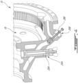
- FIG. 4 an enhanced view of the power section of engine 10 is shown, with two exemplary options for inlets 26 to the lubrication system 20.
- These inlets 26 may be, for instance, existing engine ports of engine 10.
- Each inlet 26A, 26B may be fluidly connected to the flow measuring system 30 and may be selected based on the particular oil nozzle(s) 24 to be tested, with plugs 28A, 28B provided to seal the other inlet 26A, 26B.
- plugs 28 may be operable to fluidly isolate the one or more oil nozzles 24 to be tested from the rest of the lubrication system 20 so that a closed-loop testing circuit may be created between the flow measuring system and the engine 10, as discussed above.
- Such plugs may be inserted into various existing ports of the engine 10 based on the location(s) of the oil nozzle(s) 24 to be tested.
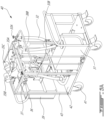
- the flow measuring system 30 may be provided in the form of a transportable cart 40 with wheels 41, illustratively four caster wheels, a base 42, and various support structures 43 (illustratively various upright supports, horizontal supports, and a handle). Flow measuring system 30 may thus be easily transportable to where the engine 10 is located, for instance at the wing of an aircraft, to perform on-wing testing and blockage/obstruction detection. In other embodiments, the flow measuring system 30 may be provided as a fixed or permanent installation.
- flow measuring system 30 may include a external supply 31 of a testing liquid, illustratively an oil tank disposed on the base 42 of the transportable cart 40, various conduits 32, a first pump 33 and a second pump 34.
- the volume of the oil tank may vary, for instance based on the size of the engine 10 and the quantity of testing liquid needed for a test.
- the conduits 32 may include flexible hoses and appropriate fittings. Additional conduits (not shown) are fluidly connectable to an system inlet 36, also referred to as a return, and a system outlet 37 of the flow measuring system for fluid connection to the engine 10.
- Flow measuring device 35 illustratively includes a flowmeter 35A, for instance a Coriolis flowmeter, a pressure transducer 35B, and a flow indicator 35C.
- First pump 33 may be a pressure pump provided with a first filter 38A (pressure filter), while second pump 34 may be a scavenge pump provided with a second filter 38B (scavenge filter).
- First pump 33 may be provided with a pressure regulating valve 33A and a pump overflow valve 33B.
- An electric cabinet 39 may be provided to control the various operations of the flow measuring system 30, and may include means to record and store flow measurement data. Other control means may be contemplated.
- the first pump 33 is operable to direct the testing fluid to the lubrication system 20 of engine 10 at inlet 26 upstream of the nozzle(s) 24, while the second pump 34 is operable to draw the testing fluid from the lubrication system 20 via outlet 27 downstream of the nozzle(s) 24, thereby allowing the testing fluid to circulate through the nozzle(s) 24 and detect any obstructions by measuring the flow of the testing fluid.
- Flow measuring system 30 may be provided with an on-board power supply such as a battery (not shown), or alternatively may be powered by an external power source.
- a calibration circuit 50 may be provided for calibrating the flow measuring system 30.
- Calibration circuit 50 illustratively includes an inlet 56, conduits or tubing 52, one or more calibration nozzles 54 (illustratively two calibration nozzles 54A, 54B), additional pathways 52A, and an outlet 57.
- the calibration nozzle(s) 54 are provided in an unblocked or ideal state.
- the flow measuring system 30 may be fluidly connected to the calibration circuit 50 in the same manner as described above with reference to the engine 10.
- the testing fluid may be circulated through the calibration circuit 50 to measure the flow resistance through the calibration nozzle(s) 54 to establish baseline value(s) for the nozzle(s) 54, which may be indicative of expected measurements for corresponding nozzle(s) 24 of engine 10 in a completely unblocked state.
- the same tests may then be performed at nozzle(s) 24 in the engine 10 to obtain actual values for the nozzle(s) 24.
- a comparison between baseline and actual values may then be performed to determine the condition of the nozzle(s) 24, as will be discussed in further detail below.
- the calibration nozzle(s) 54 may correspond to the nozzle(s) 24 to be tested in the engine 10. By correspond, the calibration nozzle(s) 54 may, for instance, have the same number, size, shape, etc. as the nozzle(s) 24 to be tested.
- Various nozzles 54 may be provided in calibration circuit 50 so that calibration circuit 50 may be used with different engines having a variety of nozzles 24, with different selection means contemplated for circulating the testing liquid in the corresponding nozzle(s) 54.
- the flow measuring system 30 may additionally include temperature and pressure sensors (not shown), as well as a fluid heater so that the conditions of the testing fluid (i.e., temperature and pressure) may be set to match those in the engine 10 for added calibration precision.
- the flow measuring system 30 may include the calibration circuit 50.
- the cart 40 may include the calibration circuit 50 so that the calibration process may be performed at any location, for instance adjacent the aircraft before the nozzle(s) 24 in the engine are tested.
- the calibration circuit 50 may be a separate installation from the flow measuring system 30 and may be either stationary or portable (e.g., provided on an additional cart). Other configurations for the calibration circuit 50 may be contemplated.
- a baseline flow measurement for the oil nozzle(s) 24 is determined by flowing a testing liquid, for instance oil, through one or more unblocked nozzles 54 corresponding to the oil nozzle(s) 24, and the flow resistance through the unblocked nozzle(s) 54 is measured. Then, the testing liquid is flowed through the oil nozzle(s) 24. The flow resistance of the testing liquid through the oil nozzle(s) 24 is measured and compared with the flow resistance of the testing liquid through the unblocked nozzle(s) 54.
- a testing liquid for instance oil
- the testing liquid may be provided by the flow measuring system to the nozzle(s) 24 at a fixed delivery pressure, with the flow measuring device 35 measuring any fluctuations (i.e., decreases) in the flow rate of the testing liquid which may be indicative of one or more blockages or obstructions in the nozzle(s) 24.
- a target or predetermined flow rate of the testing liquid may be set, and the pressure of the first pump 33 required to maintain this target flow rate may be indicative of one or more blockages or obstructions in the nozzle(s) 24.
- Various combinations of these testing methods, as well as other testing methods, may be contemplated.
- control of the flow rate and pressure of the testing liquid exiting the flow measuring system 30 may be controlled by, for instance, controls provided in the electric cabinet 39 and/or via the pressure regulating valve 33A.
- the actual flow resistance offered by the nozzle(s) 24 is greater than the baseline flow resistance measured at the calibration nozzle(s) 54, this can be indicative of the nozzle(s) 24 being at least partially obstructed.
- the magnitude of the difference between the actual flow resistance at nozzle(s) 24 and the baseline flow resistance at calibration nozzle(s) 54 can be used to quantify the obstruction and aid in determining whether or not maintenance is required. For instance, one or more predetermined thresholds may be set for this difference, and one this threshold(s) has been met, a determination may be made that the nozzle(s) 24 is/are obstructed. Additional thresholds may be indicative of a need to provide maintenance to the nozzle(s) 24.
- a first (lower) threshold being met may be indicative of a blockage in one or more nozzles 24 that merit monitoring, while a second (higher) threshold being met may be indicative of a blockage in one or more nozzles 24 that requires immediate attention.
- Other thresholds may be contemplated.
- the flow measuring system 30 may be provided as an automated or semi-automated testing system rather than a portable cart 40, where suitable valves are used to isolate the nozzle(s) 24 from the lubrication system 20 and fluidly connect the nozzle(s) 24 to a controlled (test) testing fluid source for the purpose of testing the oil nozzles for obstruction (i.e., increased flow resistance).
- a controlled (test) testing fluid source for the purpose of testing the oil nozzles for obstruction (i.e., increased flow resistance).
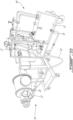
- FIGS. 6A-6B two exemplary flow measuring systems 30 are shown fluidly coupled to a hot section of a gas turbine engine 10 (i.e., the combustor 16 turbine section 18).
- a flow measuring system 30 which includes a scavenge pump 34 operable to draw the testing fluid away from the engine 10 via outlet 27. Scavenge pump 34 then directs the testing fluid into the external supply 31 via conduit 32.
- the scavenge pump 34, along with the various plugs 28, may minimize the risk of contamination of testing liquid to the other portions of the engine 10.
- scavenge pump 34 is omitted, and flow measuring system 30 relies on a gravity drain from outlet 27 to draw the testing fluid away from the engine 10.
- Other configurations may be contemplated.
- At least some embodiments disclose systems and methods for measuring a flow of a testing liquid through one or more oil nozzles in an aircraft engine, thereby allowing any obstructions or partial/full blockages in these nozzles to be detected without requiring disassembly of the engine for visual inspection.
Landscapes
- Engineering & Computer Science (AREA)
- Mechanical Engineering (AREA)
- General Engineering & Computer Science (AREA)
- Chemical & Material Sciences (AREA)
- Combustion & Propulsion (AREA)
- Physics & Mathematics (AREA)
- General Physics & Mathematics (AREA)
- Testing Of Devices, Machine Parts, Or Other Structures Thereof (AREA)
- Measuring Volume Flow (AREA)
Abstract
Description
- The present disclosure relates generally to aircraft engines and, more particularly, to lubricant systems used in such engines.
- For some aircraft engines, such as gas turbine engines, some parts may remain hot after the engine is shut down. For instance, a turbine disk of a low-pressure or power turbine, which may be a heavy component having an important thermal mass, may retain its heat after shut down. This heat may radiate to neighboring components. It was observed that, in some instances, the heat from the turbine disk radiates toward oil nozzles of a lubricant system. In turn, this heat may cause the oil to coke, thereby blocking one or more oil nozzles. Thus, the blocked oil nozzles may not be able to supply oil to lubricate nearby component, which may therefore see an impairment in their performance.
- In one aspect of the invention, there is provided a flow measuring system for one or more oil nozzles of a lubrication system of an aircraft engine, comprising: an external supply of a testing liquid; a pump fluidly connecting the external supply of the testing liquid to an inlet of the lubrication system via a first conduit, the inlet to the lubrication system disposed upstream of the one or more oil nozzles; a second conduit fluidly connecting an outlet of the lubrication system to the external supply of the testing liquid, the outlet of the lubrication system disposed downstream of the one or more oil nozzles; and a flow measuring device operable to measure a flow resistance through the one or more oil nozzles.
- In another aspect of the invention, there is provided a system for detecting obstructions in one or more oil nozzles of a lubrication system of an aircraft engine, comprising: a flow measuring unit having an external supply of a testing liquid, a pump fluidly coupled to an outlet of the flow measuring unit, a flow measuring device operable to measure a flow resistance through the one or more oil nozzles, and an inlet of the flow measuring unit; and a calibration circuit having one or more calibration nozzles corresponding to the one or more oil nozzles of the lubrication system, an inlet of the calibration circuit fluidly connectable to the outlet of the flow measuring device and disposed upstream of the one or more calibration nozzles, and an outlet of the calibration circuit fluidly connectable to the inlet of the flow measuring device and disposed downstream of the one or more calibration nozzles; wherein the flow measuring unit is operable to circulate the testing liquid through the calibration circuit to measure a baseline flow measurement for the one or more calibration nozzles and to circulate the testing liquid through the one or more oil nozzles of the lubrication system to compare a flow measurement through the one or more oil nozzles to the baseline flow measurement.
- In an embodiment of the above, the flow measuring unit further includes an additional pump fluidly coupled to the inlet of the flow measuring unit.
- In an embodiment of any of the above, the pump is operable to deliver the testing liquid to the one or more oil nozzles at a fixed delivery pressure, and the flow measuring device is operable to measure a reduction in a flow rate of the testing liquid through the one or more oil nozzles at the fixed delivery pressure.
- In an embodiment of any of the above, the pump is operable to modulate a delivery pressure of the testing liquid to the one or more oil nozzles to maintain a predetermined flow rate, and the flow measuring device is operable to measure the delivery pressure required to maintain the predetermined flow rate.
- In an embodiment of any of the above, the flow measuring unit is portable.
- An embodiment of any of the above further comprises one or more plugs insertable into one or more ports of the aircraft engine to create a closed circuit between the external supply of the testing liquid and the one or more oil nozzles.
- In an embodiment of any of the above, the external supply of the testing liquid contains oil.
- In another aspect of the invention, there is provided a method for detecting obstructions in an oil nozzle of an aircraft engine, comprising: determining a baseline flow measurement for the oil nozzle by flowing a testing liquid through an unblocked nozzle corresponding to the oil nozzle and measuring a flow resistance through the unblocked nozzle; flowing the testing liquid through the oil nozzle; measuring a flow resistance of the testing liquid through the oil nozzle; and comparing the flow resistance of the testing liquid through the oil nozzle with the flow resistance of the testing liquid through the unblocked nozzle.
- Reference is now made to the accompanying figures in which:
-
FIG. 1 is a schematic cross sectional view of a gas turbine engine; -
FIG. 2 is a block diagram of an exemplary lubrication system for a gas turbine engine; -
FIG. 3 is a block diagram of a flow measuring system for a gas turbine engine; -
FIG. 4 is an enhanced, partial cross sectional view of the gas turbine engine ofFIG. 1 ; -
FIGS. 5A-5B are front and rear perspective views, respectively, of a portable cart for a flow measuring system; and -
FIGS. 6A-6B are perspective views of exemplary flow measuring systems fluidly coupled to a gas turbine engine. -
FIG. 1 illustrates agas turbine engine 10 of a type preferably provided for use in subsonic flight, generally comprising in serial flow communication afan 12 through which ambient air is propelled, acompressor section 14 for pressurizing the air, acombustor 16 in which the compressed air is mixed with fuel and ignited for generating an annular stream of hot combustion gases, and aturbine section 18 for extracting energy from the combustion gases. WhileFIG. 1 depictsgas turbine engine 10 to be a turbofan-type engine, the present disclosure is applicable to other types of aircraft engines, for instance turboprop or turbojettype engines, as well as hybrid or compounded engines. - Referring to
FIG. 2 ,engine 10 includes alubrication system 20 operable to circulating a lubricant, such as oil, through various components to provide lubrication and/or cooling. The lubricant may be stored in anonboard container 21 and may be circulated throughout theengine 10 viavarious conduits 22,pumps 23 andnozzles 24 which may direct the lubricant towardsvarious components 25 requiring lubrication and/or cooling, and then return the lubricant to thecontainer 21. The lubricant may follow various additional defined orundefined pathways 22A between thenozzles 24,components 25 andpumps 23. It is understood thatFIG. 2 is a simplified depiction of a lubrication system forengine 10, and various additional components such as filters, heat exchangers, etc. are omitted for clarity. - In a specific embodiment of a
lubrication system 20, and as shown inFIG. 3 , oil may be directed via one or more oil nozzles 24 (twooil nozzles components turbine section 18 of theengine 10. Upon shutdown of the engine, residual heat from theturbine section 18 may radiate towards theoil nozzles 24, which may cause any remaining oil in theoil nozzles 24 to coke or otherwise harden. One ormore oil nozzles 24 may thus become at least partially blocked, which may negatively impact the operability of the lubrication system. It is understood this embodiment (i.e., the location of the oil nozzles) is exemplary, and the present disclosure is applicable tooil nozzles 24 in other locations throughoutengine 10 where they may be susceptible to partial or full blockage to due, for instance, residual radiating heat from a nearby component. - As shown in
FIG. 3 , aflow measuring system 30, also referred to as a flow measuring unit, is provided externally from and adjacent theengine 10 for testing or monitoring the flow resistance through one ormore oil nozzles 24 in theengine 10, for instance in theturbine section 18 of theengine 10, and for detecting obstructions in the one ormore oil nozzles 24.Oil nozzles 24 may become blocked or obstructed for a variety of reasons, for instance due to residual oil in thenozzles 24 coking due to residual heat in nearby components, such as in theturbine section 18 ofengine 10. Theflow measuring system 30 includes anexternal supply 31 of a testing liquid for circulating through thelubrication system 20, and various conduits ortubing 32 for fluidly connecting theflow measuring system 30 to the lubrication system 20 (i.e., to the engine 10). Byexternal supply 31, it is understood that the testing liquid is distinct from the lubricant used inlubrication system 20. In some cases, the testing liquid is selected to match the lubricant used in thelubrication system 20, for instance a specific type of oil. Other testing liquids may be contemplated. As will be discussed in further detail below, this externally-contained testing liquid, distinct from the engine's lubricant, is circulated through thelubrication system 20 to detect any partial or full blockages or obstructions in one ormore nozzles 24. -
Flow measuring system 30 includes afirst pump 33 fluidly connecting theexternal supply 31 of the testing liquid to aninlet 26 of thelubrication system 20, theinlet 26 disposed upstream of the oil nozzle(s) 24 to be tested.Various inlets 26 may be contemplated, as will be discussed in further detail below. Thesystem 30 may further include a second pump 34 (also referred to as an additional pump) fluidly connected to anoutlet 27 of thelubrication system 20, theoutlet 27 disposed downstream of the oil nozzle(s) 24 to be tested. In other cases, thesecond pump 34 may be omitted, with testing liquid draining via gravity from theoutlet 27 of thelubrication system 20 back to theexternal supply 31, as will be discussed in further detail below.Various outlets 27 may be contemplated, as will be discussed in further detail below.Flow measuring system 30 further includes one or moreflow measuring device 35, illustratively disposed between thefirst pump 33 and the inlet 26 (other positions may be contemplated), and operable to measure a flow resistance through the nozzle(s) 24. Various types offlow measuring devices 35 may be contemplated, as will be discussed in further detail below. -
FIG. 3 therefore shows a closed-loop testing circuit between theflow measuring system 30 and thelubrication system 20 where testing fluid is circulated from theexternal supply 31 viavarious conduits 32 andfirst pump 33 to theinlet 26 of thelubrication system 20. The testing fluid is then directed through one ormore oil nozzles outlet 27 and flowing back to theexternal supply 31 viaconduit 32, either aided by second pump 34 (as shown inFIG. 3 ) or by gravity drain.Flow measuring device 35, illustratively disposed betweenfirst pump 33 andinlet 26, measures the flow rate of the flowing testing fluid. One or more plugs may be used to seal off the one ormore oil nozzles lubrication system 20, thereby creating this closed-loop system, as will be discussed in further detail below. - Referring to
FIG. 4 , an enhanced view of the power section ofengine 10 is shown, with two exemplary options forinlets 26 to thelubrication system 20. Theseinlets 26 may be, for instance, existing engine ports ofengine 10. Eachinlet flow measuring system 30 and may be selected based on the particular oil nozzle(s) 24 to be tested, withplugs other inlet more oil nozzles 24 to be tested from the rest of thelubrication system 20 so that a closed-loop testing circuit may be created between the flow measuring system and theengine 10, as discussed above. Such plugs may be inserted into various existing ports of theengine 10 based on the location(s) of the oil nozzle(s) 24 to be tested. - Referring to
FIGS. 5A-5B , in an exemplary embodiment theflow measuring system 30 may be provided in the form of atransportable cart 40 withwheels 41, illustratively four caster wheels, abase 42, and various support structures 43 (illustratively various upright supports, horizontal supports, and a handle). Flow measuringsystem 30 may thus be easily transportable to where theengine 10 is located, for instance at the wing of an aircraft, to perform on-wing testing and blockage/obstruction detection. In other embodiments, theflow measuring system 30 may be provided as a fixed or permanent installation. - As discussed above,
flow measuring system 30 may include aexternal supply 31 of a testing liquid, illustratively an oil tank disposed on thebase 42 of thetransportable cart 40,various conduits 32, afirst pump 33 and asecond pump 34. The volume of the oil tank may vary, for instance based on the size of theengine 10 and the quantity of testing liquid needed for a test. Theconduits 32 may include flexible hoses and appropriate fittings. Additional conduits (not shown) are fluidly connectable to ansystem inlet 36, also referred to as a return, and asystem outlet 37 of the flow measuring system for fluid connection to theengine 10. Flow measuringdevice 35 illustratively includes aflowmeter 35A, for instance a Coriolis flowmeter, apressure transducer 35B, and aflow indicator 35C. Other components may be contemplated. First pump 33 may be a pressure pump provided with afirst filter 38A (pressure filter), whilesecond pump 34 may be a scavenge pump provided with asecond filter 38B (scavenge filter). First pump 33 may be provided with apressure regulating valve 33A and apump overflow valve 33B. Anelectric cabinet 39 may be provided to control the various operations of theflow measuring system 30, and may include means to record and store flow measurement data. Other control means may be contemplated. As discussed above, thefirst pump 33 is operable to direct the testing fluid to thelubrication system 20 ofengine 10 atinlet 26 upstream of the nozzle(s) 24, while thesecond pump 34 is operable to draw the testing fluid from thelubrication system 20 viaoutlet 27 downstream of the nozzle(s) 24, thereby allowing the testing fluid to circulate through the nozzle(s) 24 and detect any obstructions by measuring the flow of the testing fluid. Flow measuringsystem 30 may be provided with an on-board power supply such as a battery (not shown), or alternatively may be powered by an external power source. - Referring again to
FIG. 3 , acalibration circuit 50 may be provided for calibrating theflow measuring system 30.Calibration circuit 50 illustratively includes aninlet 56, conduits or tubing 52, one or more calibration nozzles 54 (illustratively twocalibration nozzles additional pathways 52A, and anoutlet 57. The calibration nozzle(s) 54 are provided in an unblocked or ideal state. As such, theflow measuring system 30 may be fluidly connected to thecalibration circuit 50 in the same manner as described above with reference to theengine 10. The testing fluid may be circulated through thecalibration circuit 50 to measure the flow resistance through the calibration nozzle(s) 54 to establish baseline value(s) for the nozzle(s) 54, which may be indicative of expected measurements for corresponding nozzle(s) 24 ofengine 10 in a completely unblocked state. The same tests may then be performed at nozzle(s) 24 in theengine 10 to obtain actual values for the nozzle(s) 24. A comparison between baseline and actual values may then be performed to determine the condition of the nozzle(s) 24, as will be discussed in further detail below. - The calibration nozzle(s) 54 may correspond to the nozzle(s) 24 to be tested in the
engine 10. By correspond, the calibration nozzle(s) 54 may, for instance, have the same number, size, shape, etc. as the nozzle(s) 24 to be tested. Various nozzles 54 may be provided incalibration circuit 50 so thatcalibration circuit 50 may be used with different engines having a variety ofnozzles 24, with different selection means contemplated for circulating the testing liquid in the corresponding nozzle(s) 54. Theflow measuring system 30 may additionally include temperature and pressure sensors (not shown), as well as a fluid heater so that the conditions of the testing fluid (i.e., temperature and pressure) may be set to match those in theengine 10 for added calibration precision. - While the
calibration circuit 50 inFIG. 3 is illustratively shown to be distinct from theflow measuring system 30, in various embodiments theflow measuring system 30 may include thecalibration circuit 50. For instance, thecart 40 may include thecalibration circuit 50 so that the calibration process may be performed at any location, for instance adjacent the aircraft before the nozzle(s) 24 in the engine are tested. Alternatively, thecalibration circuit 50 may be a separate installation from theflow measuring system 30 and may be either stationary or portable (e.g., provided on an additional cart). Other configurations for thecalibration circuit 50 may be contemplated. - According to the present disclosure, there is taught a method for detecting obstructions in one or
more oil nozzles 24 of anaircraft engine 10. A baseline flow measurement for the oil nozzle(s) 24 is determined by flowing a testing liquid, for instance oil, through one or more unblocked nozzles 54 corresponding to the oil nozzle(s) 24, and the flow resistance through the unblocked nozzle(s) 54 is measured. Then, the testing liquid is flowed through the oil nozzle(s) 24. The flow resistance of the testing liquid through the oil nozzle(s) 24 is measured and compared with the flow resistance of the testing liquid through the unblocked nozzle(s) 54. - Various means for measuring the flow resistance through the nozzle(s) 24 may be contemplated. In a first exemplary embodiment, the testing liquid may be provided by the flow measuring system to the nozzle(s) 24 at a fixed delivery pressure, with the
flow measuring device 35 measuring any fluctuations (i.e., decreases) in the flow rate of the testing liquid which may be indicative of one or more blockages or obstructions in the nozzle(s) 24. In another exemplary embodiment, a target or predetermined flow rate of the testing liquid may be set, and the pressure of thefirst pump 33 required to maintain this target flow rate may be indicative of one or more blockages or obstructions in the nozzle(s) 24. Various combinations of these testing methods, as well as other testing methods, may be contemplated. Preferably, the same or similar conditions (e.g., fluid viscosity and temperature) should be found during the baseline tests using thecalibration circuit 50 and during the on-engine tests. Control of the flow rate and pressure of the testing liquid exiting theflow measuring system 30 may be controlled by, for instance, controls provided in theelectric cabinet 39 and/or via thepressure regulating valve 33A. - During the obstruction test, if the actual flow resistance offered by the nozzle(s) 24 is greater than the baseline flow resistance measured at the calibration nozzle(s) 54, this can be indicative of the nozzle(s) 24 being at least partially obstructed. The magnitude of the difference between the actual flow resistance at nozzle(s) 24 and the baseline flow resistance at calibration nozzle(s) 54 can be used to quantify the obstruction and aid in determining whether or not maintenance is required. For instance, one or more predetermined thresholds may be set for this difference, and one this threshold(s) has been met, a determination may be made that the nozzle(s) 24 is/are obstructed. Additional thresholds may be indicative of a need to provide maintenance to the nozzle(s) 24. For instance, a first (lower) threshold being met may be indicative of a blockage in one or
more nozzles 24 that merit monitoring, while a second (higher) threshold being met may be indicative of a blockage in one ormore nozzles 24 that requires immediate attention. Other thresholds may be contemplated. - In other embodiments, the
flow measuring system 30 may be provided as an automated or semi-automated testing system rather than aportable cart 40, where suitable valves are used to isolate the nozzle(s) 24 from thelubrication system 20 and fluidly connect the nozzle(s) 24 to a controlled (test) testing fluid source for the purpose of testing the oil nozzles for obstruction (i.e., increased flow resistance). - Referring to
FIGS. 6A-6B , two exemplaryflow measuring systems 30 are shown fluidly coupled to a hot section of a gas turbine engine 10 (i.e., thecombustor 16 turbine section 18). For simplicity, the rest of theengine 10 is omitted.FIG. 6A depicts aflow measuring system 30 which includes ascavenge pump 34 operable to draw the testing fluid away from theengine 10 viaoutlet 27.Scavenge pump 34 then directs the testing fluid into theexternal supply 31 viaconduit 32. Thescavenge pump 34, along with the various plugs 28, may minimize the risk of contamination of testing liquid to the other portions of theengine 10. In the embodiment shown inFIG. 6B , scavengepump 34 is omitted, and flow measuringsystem 30 relies on a gravity drain fromoutlet 27 to draw the testing fluid away from theengine 10. Other configurations may be contemplated. - It can be appreciated from the foregoing that at least some embodiments disclose systems and methods for measuring a flow of a testing liquid through one or more oil nozzles in an aircraft engine, thereby allowing any obstructions or partial/full blockages in these nozzles to be detected without requiring disassembly of the engine for visual inspection.
- The embodiments described in this document provide non-limiting examples of possible implementations of the present technology. Upon review of the present disclosure, a person of ordinary skill in the art will recognize that changes may be made to the embodiments described herein without departing from the scope of the present technology. Yet further modifications could be implemented by a person of ordinary skill in the art in view of the present disclosure, which modifications would be within the scope of the present technology.
Claims (15)
- A flow measuring system (30) for one or more oil nozzles (24; 24A, 24B) of a lubrication system (20) of an aircraft engine (10), comprising:an external supply (31) of a testing liquid;a pump (33) fluidly connecting the external supply (31) of the testing liquid to an inlet (26) of the lubrication system (20) via a first conduit (32), the inlet (26) to the lubrication system (20) disposed upstream of the one or more oil nozzles (24; 24A, 24B);a second conduit (32) fluidly connecting an outlet (27) of the lubrication system (20) to the external supply (31) of the testing liquid, the outlet (27) of the lubrication system (20) disposed downstream of the one or more oil nozzles (24; 24A, 24B); anda flow measuring device (35) operable to measure a flow resistance through the one or more oil nozzles (24; 24A, 24B).
- The flow measuring system (30) as defined in claim 1, further comprising an additional pump (34) fluidly coupled to the outlet (27) of the lubrication system (20) and operable to draw the testing liquid from the lubrication system (20).
- The flow measuring system (30) as defined in claim 1 or 2, further comprising a calibration circuit (50) fluidly connectable to the flow measuring system (30) and having one or more calibration nozzles (54; 54A, 54B) corresponding to the one or more oil nozzles (24; 24A, 24B) of the lubrication system (20), wherein the flow measuring device (35) is further operable to measure a baseline flow resistance through the one or more calibration nozzles (54; 54A, 54B).
- The flow measuring system (30) as defined in claim 3, wherein an inlet (56) of the calibration circuit (50) is fluidly connectable to an outlet of the flow measuring device (35) and disposed upstream of the one or more calibration nozzles (54; 54A, 54B), and an outlet (57) of the calibration circuit (50) is fluidly connectable to an inlet of the flow measuring device (35) and disposed downstream of the one or more calibration nozzles (54; 54A, 54B); and
wherein the flow measuring device is operable to circulate the testing liquid through the calibration circuit (50) to measure a baseline flow measurement for the one or more calibration nozzles (54; 54A, 54B) and to circulate the testing liquid through the one or more oil nozzles (24; 24A, 24B) of the lubrication system (20) to compare a flow measurement through the one or more oil nozzles (24; 24A, 24B) to the baseline flow measurement. - The flow measuring system (30) as defined in any preceding claim, wherein the pump (33) is operable to deliver the testing liquid to the one or more oil nozzles (24; 24A, 24B) at a fixed delivery pressure, and the flow measuring device (35) is operable to measure a reduction in a flow rate of the testing liquid through the one or more oil nozzles (24; 24A, 24B) at the fixed delivery pressure.
- The flow measuring system (30) as defined in any preceding claim, wherein the pump (33) is operable to modulate a delivery pressure of the testing liquid to the one or more oil nozzles (24; 24A, 24B) to maintain a predetermined flow rate, and the flow measuring device (35) is operable to measure the delivery pressure required to maintain the predetermined flow rate.
- The flow measuring system (30) as defined in any preceding claim, further comprising one or more plugs (28; 28A, 28B) insertable into one or more ports of the aircraft engine (10) to create a closed circuit between the external supply (31) of testing liquid and the one or more oil nozzles (24; 24A, 24B).
- The flow measuring system (30) as defined in any preceding claim, wherein the external supply (31) of the testing liquid contains oil.
- The flow measuring system (30) as defined in any preceding claim, wherein the flow measuring device is portable.
- The flow measuring system (30) as defined in any preceding claim, wherein the external supply (31) of the testing liquid contains oil.
- A method for detecting obstructions in an oil nozzle (24) of an aircraft engine (10), comprising:determining a baseline flow measurement for the oil nozzle (24) by flowing a testing liquid through an unblocked nozzle (54) corresponding to the oil nozzle (24) and measuring a flow resistance through the unblocked nozzle (54);flowing the testing liquid through the oil nozzle (24);measuring a flow resistance of the testing liquid through the oil nozzle (24); andcomparing the flow resistance of the testing liquid through the oil nozzle (24) with the flow resistance of the testing liquid through the unblocked nozzle (54),wherein, optionally, flowing the testing liquid through the oil nozzle (24) includes flowing oil from an external supply (31) of oil through the oil nozzle (24).
- The method as defined in claim 11, wherein flowing the testing liquid through the oil nozzle (24) includes flowing the testing liquid through the oil nozzle (24) at a fixed delivery pressure, and wherein the measuring the flow resistance of the testing liquid through the oil nozzle (24) includes measuring a reduction in a flow rate of the testing liquid through the oil nozzle (24) at the fixed delivery pressure.
- The method as defined in claim 11 or 12, wherein flowing the testing liquid through the oil nozzle (24) includes modulating a delivery pressure of the testing liquid through the oil nozzle (24) to maintain a predetermined flow rate, and measuring the flow resistance of the testing liquid through the oil nozzle (24) includes measuring the delivery pressure required to maintain the predetermined flow rate.
- The method as defined in any of claims 11 to 13, wherein comparing the flow resistance of the testing liquid through the oil nozzle (24) with the flow resistance of the testing liquid through the unblocked nozzle (54) further includes calculating a difference between the flow resistance of the testing liquid through the oil nozzle (24) with the flow resistance of the testing liquid through the unblocked nozzle (54) and comparing the difference to a predetermined threshold indicative of an obstruction in the oil nozzle (24).
- The method as defined in any of claims 11 to 14, further comprising providing a portable flow measuring unit including an external supply (31) of the testing liquid, and transporting the portable flow measuring unit to the aircraft engine (10) subsequently to flowing the testing liquid through the oil nozzle (24).
Applications Claiming Priority (1)
| Application Number | Priority Date | Filing Date | Title |
|---|---|---|---|
| US17/805,876 US11885710B2 (en) | 2022-06-08 | 2022-06-08 | Oil nozzle health detection using liquid flow test |
Publications (2)
| Publication Number | Publication Date |
|---|---|
| EP4290054A1 true EP4290054A1 (en) | 2023-12-13 |
| EP4290054B1 EP4290054B1 (en) | 2026-02-18 |
Family
ID=86732736
Family Applications (1)
| Application Number | Title | Priority Date | Filing Date |
|---|---|---|---|
| EP23178281.4A Active EP4290054B1 (en) | 2022-06-08 | 2023-06-08 | Oil nozzle health monitoring system for an aircraft engine |
Country Status (3)
| Country | Link |
|---|---|
| US (1) | US11885710B2 (en) |
| EP (1) | EP4290054B1 (en) |
| CA (1) | CA3201150A1 (en) |
Citations (3)
| Publication number | Priority date | Publication date | Assignee | Title |
|---|---|---|---|---|
| US10072521B2 (en) * | 2013-12-05 | 2018-09-11 | United Technologies Corporation | FDGS auxiliary pump monitoring system |
| WO2018164675A1 (en) * | 2017-03-08 | 2018-09-13 | Siemens Aktiengesellschaft | Fluid flow measurement in gas turbine engines |
| US20200340375A1 (en) * | 2017-12-20 | 2020-10-29 | Safran Aircraft Engines | Device for supplying an oil tank from a second tank |
Family Cites Families (10)
| Publication number | Priority date | Publication date | Assignee | Title |
|---|---|---|---|---|
| US4452037A (en) | 1982-04-16 | 1984-06-05 | Avco Corporation | Air purge system for gas turbine engine |
| US5193406A (en) * | 1991-06-20 | 1993-03-16 | Exxon Research And Engineering Company | On-stream method for detecting erosion or plugging for manifolded feed nozzle systems |
| US6000283A (en) | 1997-09-19 | 1999-12-14 | The United States Of America As Represented By The Secretary Of The Air Force | Testing device for oil flow problems in jet engines |
| US7966804B2 (en) | 2006-07-12 | 2011-06-28 | General Electric Company | Method and apparatus for testing gas turbine engines |
| FR2927003B1 (en) | 2008-02-06 | 2010-09-24 | Snecma | DETECTION OF THE CLOSURE OF A FILTER OF A FLUID |
| US8596417B2 (en) | 2011-07-05 | 2013-12-03 | Honeywell International Inc. | Lubrication systems with nozzle blockage detection systems |
| US11149642B2 (en) | 2015-12-30 | 2021-10-19 | General Electric Company | System and method of reducing post-shutdown engine temperatures |
| US9889995B1 (en) * | 2017-03-15 | 2018-02-13 | Core Flow Ltd. | Noncontact support platform with blockage detection |
| GB2567637B (en) * | 2017-10-17 | 2020-05-27 | Delphi Tech Ip Ltd | Injector test machine |
| US11047306B1 (en) | 2020-02-25 | 2021-06-29 | General Electric Company | Gas turbine engine reverse bleed for coking abatement |
-
2022
- 2022-06-08 US US17/805,876 patent/US11885710B2/en active Active
-
2023
- 2023-05-30 CA CA3201150A patent/CA3201150A1/en active Pending
- 2023-06-08 EP EP23178281.4A patent/EP4290054B1/en active Active
Patent Citations (3)
| Publication number | Priority date | Publication date | Assignee | Title |
|---|---|---|---|---|
| US10072521B2 (en) * | 2013-12-05 | 2018-09-11 | United Technologies Corporation | FDGS auxiliary pump monitoring system |
| WO2018164675A1 (en) * | 2017-03-08 | 2018-09-13 | Siemens Aktiengesellschaft | Fluid flow measurement in gas turbine engines |
| US20200340375A1 (en) * | 2017-12-20 | 2020-10-29 | Safran Aircraft Engines | Device for supplying an oil tank from a second tank |
Also Published As
| Publication number | Publication date |
|---|---|
| EP4290054B1 (en) | 2026-02-18 |
| CA3201150A1 (en) | 2023-12-08 |
| US11885710B2 (en) | 2024-01-30 |
| US20230400387A1 (en) | 2023-12-14 |
Similar Documents
| Publication | Publication Date | Title |
|---|---|---|
| US10302523B2 (en) | Method for testing a seal of a sealed bearing cavity | |
| CN100564811C (en) | Systems and methods for testing swirling flow devices | |
| US9746394B2 (en) | Bench test, for the characterization of a flow of a two-phase fluid | |
| CA2855802C (en) | Methods and apparatus for inspecting cooling holes | |
| JP2016525682A (en) | Apparatus and method for continuously measuring the dynamic fuel consumption of an internal combustion engine | |
| CN104897404A (en) | Experimental device and method for measuring performance of centrifugal ventilator | |
| CA2142409A1 (en) | System and method for in situ testing of the leak-tightness of a tubular member | |
| EP3875744A1 (en) | Method for fuel delivery | |
| CN104508399B (en) | A method and apparatus for improving accuracy of A/C diagnostic tests | |
| CN108956148B (en) | Oil supply and return matching test device and method for lubricating oil system | |
| KR101229454B1 (en) | Device for Common Rail Injector Test | |
| EP4290054B1 (en) | Oil nozzle health monitoring system for an aircraft engine | |
| CN107505237A (en) | Fluid metal particle sensor test system and method for testing | |
| CN104729856A (en) | Cooling water circulation system applicable to high-flow test platform | |
| US11513033B2 (en) | Gas turbine engine system with health monitoring of fuel pump condition | |
| JP5967847B2 (en) | Function test method for dynamic fuel consumption measuring device | |
| CN102279024A (en) | Method for detecting liquids inside gas return pipeline and device | |
| US6539777B1 (en) | Measuring leakage through ducts | |
| US10794333B2 (en) | General aviation carburetor testing and analysis device | |
| CN220829336U (en) | Closed flow resistance test platform | |
| CN106662019B (en) | Method for aiding in the detection of damage to piping of a turbojet engine | |
| CN209541894U (en) | Test the device of water pump noise | |
| CN114111675A (en) | Method for detecting icing thickness of pipeline under continuous water supply working condition of constant wall temperature boundary pressurized water supply system | |
| CN120008961B (en) | Performance test system and method for active and passive combined type thermal protection system | |
| CN111811798A (en) | Waterway detection system and waterway detection method |
Legal Events
| Date | Code | Title | Description |
|---|---|---|---|
| PUAI | Public reference made under article 153(3) epc to a published international application that has entered the european phase |
Free format text: ORIGINAL CODE: 0009012 |
|
| STAA | Information on the status of an ep patent application or granted ep patent |
Free format text: STATUS: THE APPLICATION HAS BEEN PUBLISHED |
|
| AK | Designated contracting states |
Kind code of ref document: A1 Designated state(s): AL AT BE BG CH CY CZ DE DK EE ES FI FR GB GR HR HU IE IS IT LI LT LU LV MC ME MK MT NL NO PL PT RO RS SE SI SK SM TR |
|
| STAA | Information on the status of an ep patent application or granted ep patent |
Free format text: STATUS: REQUEST FOR EXAMINATION WAS MADE |
|
| 17P | Request for examination filed |
Effective date: 20240613 |
|
| RBV | Designated contracting states (corrected) |
Designated state(s): AL AT BE BG CH CY CZ DE DK EE ES FI FR GB GR HR HU IE IS IT LI LT LU LV MC ME MK MT NL NO PL PT RO RS SE SI SK SM TR |
|
| GRAP | Despatch of communication of intention to grant a patent |
Free format text: ORIGINAL CODE: EPIDOSNIGR1 |
|
| STAA | Information on the status of an ep patent application or granted ep patent |
Free format text: STATUS: GRANT OF PATENT IS INTENDED |
|
| INTG | Intention to grant announced |
Effective date: 20250912 |
|
| GRAS | Grant fee paid |
Free format text: ORIGINAL CODE: EPIDOSNIGR3 |
|
| GRAA | (expected) grant |
Free format text: ORIGINAL CODE: 0009210 |
|
| STAA | Information on the status of an ep patent application or granted ep patent |
Free format text: STATUS: THE PATENT HAS BEEN GRANTED |
|
| AK | Designated contracting states |
Kind code of ref document: B1 Designated state(s): AL AT BE BG CH CY CZ DE DK EE ES FI FR GB GR HR HU IE IS IT LI LT LU LV MC ME MK MT NL NO PL PT RO RS SE SI SK SM TR |
|
| REG | Reference to a national code |
Ref country code: CH Ref legal event code: F10 Free format text: ST27 STATUS EVENT CODE: U-0-0-F10-F00 (AS PROVIDED BY THE NATIONAL OFFICE) Effective date: 20260218 Ref country code: GB Ref legal event code: FG4D |
|
| REG | Reference to a national code |
Ref country code: DE Ref legal event code: R096 Ref document number: 602023012076 Country of ref document: DE |
|
| REG | Reference to a national code |
Ref country code: IE Ref legal event code: FG4D |
|
| REG | Reference to a national code |
Ref country code: NL Ref legal event code: MP Effective date: 20260218 |
|
| PG25 | Lapsed in a contracting state [announced via postgrant information from national office to epo] |
Ref country code: RS Free format text: LAPSE BECAUSE OF FAILURE TO SUBMIT A TRANSLATION OF THE DESCRIPTION OR TO PAY THE FEE WITHIN THE PRESCRIBED TIME-LIMIT Effective date: 20260518 |
|
| PG25 | Lapsed in a contracting state [announced via postgrant information from national office to epo] |
Ref country code: ES Free format text: LAPSE BECAUSE OF FAILURE TO SUBMIT A TRANSLATION OF THE DESCRIPTION OR TO PAY THE FEE WITHIN THE PRESCRIBED TIME-LIMIT Effective date: 20260218 |
|
| PG25 | Lapsed in a contracting state [announced via postgrant information from national office to epo] |
Ref country code: PL Free format text: LAPSE BECAUSE OF FAILURE TO SUBMIT A TRANSLATION OF THE DESCRIPTION OR TO PAY THE FEE WITHIN THE PRESCRIBED TIME-LIMIT Effective date: 20260218 |
|
| PG25 | Lapsed in a contracting state [announced via postgrant information from national office to epo] |
Ref country code: GR Free format text: LAPSE BECAUSE OF FAILURE TO SUBMIT A TRANSLATION OF THE DESCRIPTION OR TO PAY THE FEE WITHIN THE PRESCRIBED TIME-LIMIT Effective date: 20260519 |
|
| REG | Reference to a national code |
Ref country code: LT Ref legal event code: MG9D |
|
| PG25 | Lapsed in a contracting state [announced via postgrant information from national office to epo] |
Ref country code: LT Free format text: LAPSE BECAUSE OF FAILURE TO SUBMIT A TRANSLATION OF THE DESCRIPTION OR TO PAY THE FEE WITHIN THE PRESCRIBED TIME-LIMIT Effective date: 20260218 |
|
| PGFP | Annual fee paid to national office [announced via postgrant information from national office to epo] |
Ref country code: DE Payment date: 20260520 Year of fee payment: 4 |
|
| PG25 | Lapsed in a contracting state [announced via postgrant information from national office to epo] |
Ref country code: NO Free format text: LAPSE BECAUSE OF FAILURE TO SUBMIT A TRANSLATION OF THE DESCRIPTION OR TO PAY THE FEE WITHIN THE PRESCRIBED TIME-LIMIT Effective date: 20260518 |
|
| PG25 | Lapsed in a contracting state [announced via postgrant information from national office to epo] |
Ref country code: AT Free format text: LAPSE BECAUSE OF FAILURE TO SUBMIT A TRANSLATION OF THE DESCRIPTION OR TO PAY THE FEE WITHIN THE PRESCRIBED TIME-LIMIT Effective date: 20260218 Ref country code: FI Free format text: LAPSE BECAUSE OF FAILURE TO SUBMIT A TRANSLATION OF THE DESCRIPTION OR TO PAY THE FEE WITHIN THE PRESCRIBED TIME-LIMIT Effective date: 20260218 Ref country code: SE Free format text: LAPSE BECAUSE OF FAILURE TO SUBMIT A TRANSLATION OF THE DESCRIPTION OR TO PAY THE FEE WITHIN THE PRESCRIBED TIME-LIMIT Effective date: 20260218 |
|
| REG | Reference to a national code |
Ref country code: AT Ref legal event code: MK05 Ref document number: 1888230 Country of ref document: AT Kind code of ref document: T Effective date: 20260218 |
|
| PG25 | Lapsed in a contracting state [announced via postgrant information from national office to epo] |
Ref country code: HR Free format text: LAPSE BECAUSE OF FAILURE TO SUBMIT A TRANSLATION OF THE DESCRIPTION OR TO PAY THE FEE WITHIN THE PRESCRIBED TIME-LIMIT Effective date: 20260218 |
|
| PG25 | Lapsed in a contracting state [announced via postgrant information from national office to epo] |
Ref country code: IS Free format text: LAPSE BECAUSE OF FAILURE TO SUBMIT A TRANSLATION OF THE DESCRIPTION OR TO PAY THE FEE WITHIN THE PRESCRIBED TIME-LIMIT Effective date: 20260618 Ref country code: PT Free format text: LAPSE BECAUSE OF FAILURE TO SUBMIT A TRANSLATION OF THE DESCRIPTION OR TO PAY THE FEE WITHIN THE PRESCRIBED TIME-LIMIT Effective date: 20260618 |
|
| PG25 | Lapsed in a contracting state [announced via postgrant information from national office to epo] |
Ref country code: NL Free format text: LAPSE BECAUSE OF FAILURE TO SUBMIT A TRANSLATION OF THE DESCRIPTION OR TO PAY THE FEE WITHIN THE PRESCRIBED TIME-LIMIT Effective date: 20260218 |
|
| PGFP | Annual fee paid to national office [announced via postgrant information from national office to epo] |
Ref country code: FR Payment date: 20260520 Year of fee payment: 4 |
|
| PG25 | Lapsed in a contracting state [announced via postgrant information from national office to epo] |
Ref country code: LV Free format text: LAPSE BECAUSE OF FAILURE TO SUBMIT A TRANSLATION OF THE DESCRIPTION OR TO PAY THE FEE WITHIN THE PRESCRIBED TIME-LIMIT Effective date: 20260218 |
|
| PG25 | Lapsed in a contracting state [announced via postgrant information from national office to epo] |
Ref country code: BG Free format text: LAPSE BECAUSE OF FAILURE TO SUBMIT A TRANSLATION OF THE DESCRIPTION OR TO PAY THE FEE WITHIN THE PRESCRIBED TIME-LIMIT Effective date: 20260218 |